Embed Size (px)
Citation preview

M2230x-x 4.3 handset user manual
please select the language
English
Français
Italiano
Polski
Español
Português
eština
Sloven ina
Suomi
Norsk
Svenska
Dansk

VER:1.0 │ │ 31.03.2014
ABB-Welcome M
Pos: 2 /DinA4 - Anl eitun gen Online /Inh alt/KNX/Doo rEntry /832 20-AP- xxx/Tit elblat t - 832 20-AP-xxx - ABB @ 1 9\m od_ 132 3249 806 476 _15. docx @ 11 108 4 @ @ 1
M22301-.M22302-.M22303-.4.3" Video handsetindoor station
=== E nde der Liste für Tex tma rke C over == =
ABB-Welcome
| — 2 —
Pos: 4 /Busc h-Ja ege r (N eust rukt ur)/ Mo dul-St ruktu r/Onli ne-D oku ment ation /Inh altsve rzeich nis ( --> Fü r alle Doku men te <-- )/In haltsve rzeic hnis @ 19\ mod _13 206 490 4438 6_1 5.d ocx @ 109 653 @ @ 1
1 Safety ....................................................................................................... 32 Intended use ............................................................................................. 33 Environment .............................................................................................. 3
3.1 ABB devices ............................................................................. 34 Operations ................................................................................................ 5
4.1 Standard operations .................................................................. 54.1.1 Control elements ....................................................................... 54.2 Control actions .......................................................................... 84.2.1 Incoming call / In a call .............................................................. 84.2.2 Display & volume settings during calling................................... 104.2.3 Communication menu ............................................................. 114.3 Settings .................................................................................. 144.3.1 Overview ................................................................................ 144.3.2 Intercom call settings ............................................................... 154.3.3 Switch actuator settings ........................................................... 174.3.4 Program button settings .......................................................... 184.3.5 Call forward settings ................................................................ 194.3.6 Auto unlock settings ................................................................ 204.3.7 OS password settings ............................................................. 214.3.8 Ringtone settings .................................................................... 224.3.9 Volume settings ...................................................................... 234.3.10 Date and time settings ............................................................. 244.3.11 Door entry system settings ...................................................... 254.3.12 Blacklist settings ..................................................................... 264.3.13 History review ......................................................................... 274.3.14 Language settings ................................................................... 294.3.15 Information.............................................................................. 294.3.16 Reset factory default ............................................................... 304.4 Cleaning ................................................................................. 314.5 Adjusting the device ................................................................ 32
5 Technical data......................................................................................... 336 Mounting / Installation.............................................................................. 34
6.1 Requirements for the electrician............................................... 346.2 General installation instructions ............................................... 356.3 Mounting ................................................................................. 36
=== E nde der Liste für Tex tma rke TOC == =
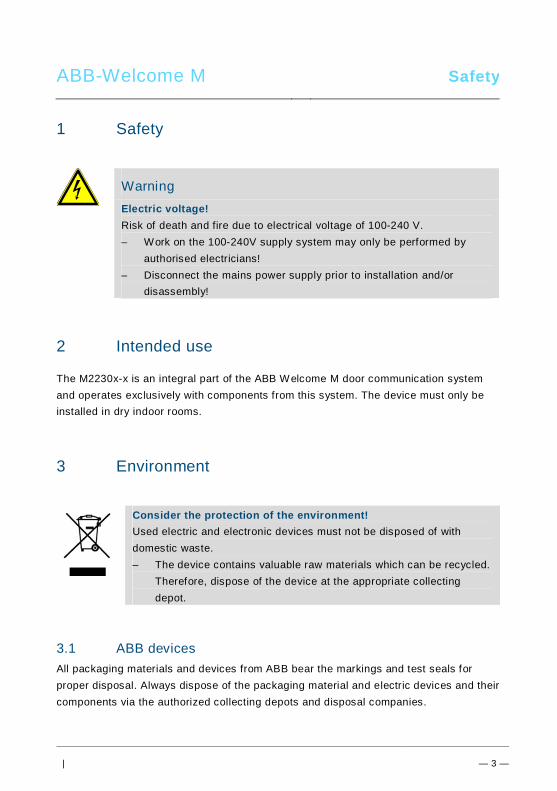
ABB-Welcome M Safety
| — 3 —
Pos: 6 /Busc h-Ja ege r (N eust rukt ur)/ Mo dul-St ruktu r/Onli ne-D oku ment ation /Übe rschri ften (- -> Für alle D okum ent e < --)/ 1. Eb ene/S - T /Sicher heit @ 18\ mod _13 026 127 917 90_ 15.d ocx @ 103 357 @ 1 @ 1
1 SafetyPos: 7 /Busc h-Ja ege r (N eust rukt ur)/ Mo dul-St ruktu r/Onli ne-D oku ment ation /Sicher heit (-- > Für alle Dok um ente <- -)/Wa rn hinweise /Sicher heit - 23 0 V @ 18\m od_ 130 260 681 675 0_15 .docx @ 1 033 08 @ @ 1
WarningElectric voltage!Risk of death and fire due to electrical voltage of 100-240 V.– Work on the 100-240V supply system may only be performed by
authorised electricians!– Disconnect the mains power supply prior to installation and/or
disassembly!
Pos: 8 /Busc h-Ja ege r (N eust rukt ur)/ Mo dul-St ruktu r/Onli ne-D oku ment ation /Übe rschri ften (- -> Für alle D okum ent e < --)/ 1. Eb ene/A - F /Bestim mun gsge mä ßer Geb rau ch @ 18\ mod _13 027 6332 131 6_1 5.do cx @ 1034 83 @ 1 @ 1
2 Intended usePos: 9 /DinA4 - Anl eitun gen Online /Inh alt/KNX/Doo rEntry /832 20-AP- xxx/Besti mmu ngsg em aesse r Ge bra uch - 83 220 -AP-xxx- 500 @ 2 0\mo d_1 324 561 168 699 _15. docx @ 11 272 8 @ @ 1
The M2230x-x is an integral part of the ABB Welcome M door communication systemand operates exclusively with components from this system. The device must only beinstalled in dry indoor rooms.
Pos: 10 /B usch-J aeg er (Neus truk tur )/M odul -Strukt ur/O nline -Doku me ntatio n/Übe rsch rifte n ( --> Fü r alle Doku men te < -- )/1. E bene /U - Z/U mwelt @ 18\ mod _13 026 141 5896 7_1 5.d ocx @ 103 383 @ 1 @ 1
3 EnvironmentPos: 11 /B usch-J aeg er (Neus truk tur )/M odul -Strukt ur/O nline -Doku me ntatio n/Umw elt ( --> Für all e Doku me nte <-- )/Hinweis e/Hinw eis - U mwelt - Hinweis Elektr oge räte @ 1 8\mo d_1 302 763 973 434 _15. docx @ 10 350 0 @ @ 1
Consider the protection of the environment!Used electric and electronic devices must not be disposed of withdomestic waste.– The device contains valuable raw materials which can be recycled.
Therefore, dispose of the device at the appropriate collectingdepot.
Pos: 12 /Di nA4 - A nleitu ngen Onlin e/Ueb ersc hrift en/2 ./ABB Gera ete @ 19 \mo d_1 323 162 843 832_ 15. docx @ 11 087 5 @ 2 @ 1
3.1 ABB devicesPos: 13 /B usch-J aeg er (Neus truk tur )/M odul -Strukt ur/O nline -Doku me ntatio n/Umw elt ( --> Für all e Doku me nte <-- )/Hinweis e/Hinw eis - U mwelt - ABB Elektro ger äte @ 19\ mo d_1 3231 627 458 39_ 15.d ocx @ 110 867 @ @ 1
All packaging materials and devices from ABB bear the markings and test seals forproper disposal. Always dispose of the packaging material and electric devices and theircomponents via the authorized collecting depots and disposal companies.

ABB-Welcome M Environment
| — 4 —
ABB products meet the legal requirements, in particular the laws governing electronicand electrical devices and the REACH ordinance.(EU-Directive 2002/96/EG WEEE and 2002/95/EG RoHS)(EU-REACH ordinance and law for the implementation of the ordinance (EG)No.1907/2006)

ABB-Welcome M Operations
| — 5 —
Pos: 18 /Di nA4 - A nleitu ngen Onlin e/Ueb ersc hrift en/1 ./Bedie nun g @ 18\m od_ 130 261 392 416 5_15 .docx @ 1 033 65 @ 1 @ 1
4 OperationsPos: 19 /Di nA4 - A nleitu ngen Onlin e/Ueb ersc hrift en/2 ./Nor male r Bet rieb @ 18 \mo d_1 302 768 8209 65_ 15. docx @ 10 3540 @ 2 @ 1
4.1 Standard operationsPos: 20 /Di nA4 - A nleitu ngen Onlin e/Ueb ersc hrift en/3 ./Bedie nele men te @ 20\ mod _13 232 6022 055 9_1 5.do cx @ 1 116 47 @ 3 @ 1
4.1.1 Control elementsPos: 21 /Di nA4 - A nleitu ngen Onlin e/In halt/KNX/Do orEnt ry/83 220 -AP-xxx/Be dienel eme nte - 8 322 0-AP-xxx @ 18\ mo d_1 3032 128 536 05_ 15.d ocx @ 103 673 @ @ 1
Fig. 1 Control elements
12
3
9
4 5 6 7 8
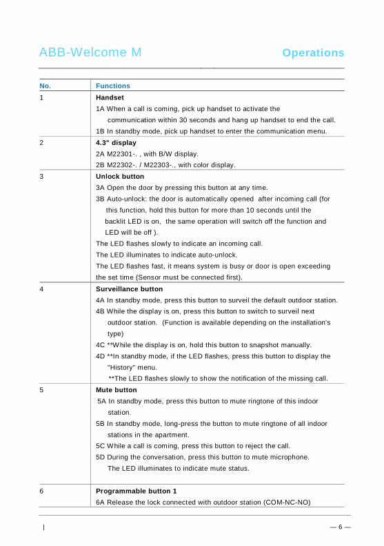
ABB-Welcome M Operations
| — 6 —
No. Functions1 Handset
1A When a call is coming, pick up handset to activate thecommunication within 30 seconds and hang up handset to end the call.
1B In standby mode, pick up handset to enter the communication menu.
2 4.3" display2A M22301-. , with B/W display.2B M22302-. / M22303-., with color display.
3 Unlock button3A Open the door by pressing this button at any time.3B Auto-unlock: the door is automatically opened after incoming call (for
this function, hold this button for more than 10 seconds until thebacklit LED is on, the same operation will switch off the function andLED will be off ).
The LED flashes slowly to indicate an incoming call.The LED illuminates to indicate auto-unlock.The LED flashes fast, it means system is busy or door is open exceedingthe set time (Sensor must be connected first).
4 Surveillance button4A In standby mode, press this button to surveil the default outdoor station.4B While the display is on, press this button to switch to surveil next
outdoor station. (Function is available depending on the installation'stype)
4C **While the display is on, hold this button to snapshot manually.4D **In standby mode, if the LED flashes, press this button to display the
"History" menu. **The LED flashes slowly to show the notification of the missing call.
5 Mute button5A In standby mode, press this button to mute ringtone of this indoor
station.5B In standby mode, long-press the button to mute ringtone of all indoor
stations in the apartment.5C While a call is coming, press this button to reject the call.5D During the conversation, press this button to mute microphone.
The LED illuminates to indicate mute status.
6 Programmable button 16A Release the lock connected with outdoor station (COM-NC-NO)
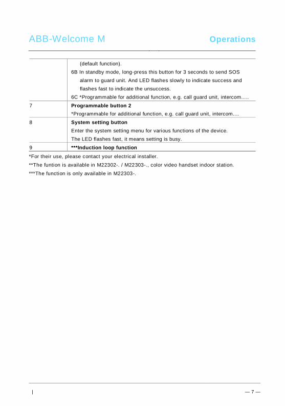
ABB-Welcome M Operations
| — 7 —
(default function).6B In standby mode, long-press this button for 3 seconds to send SOS
alarm to guard unit. And LED flashes slowly to indicate success andflashes fast to indicate the unsuccess.
6C *Programmable for additional function, e.g. call guard unit, intercom.....
7 Programmable button 2*Programmable for additional function, e.g. call guard unit, intercom....
8 System setting buttonEnter the system setting menu for various functions of the device.The LED flashes fast, it means setting is busy.
9 ***Induction loop function*For their use, please contact your electrical installer.
**The funtion is available in M22302-. / M22303-., color video handset indoor station.
***The function is only available in M22303-.Pos: 22 /B usch-J aeg er (Neus truk tur )/M odul -Strukt ur/O nline -Doku me ntatio n/Steu er mod ule - Onlin e-Dok ume ntati on ( -- > Für alle Dok ume nte <- -)/ +++ ++ ++ +++ ++ S eiten umb ruch + +++ ++ ++ +++ + @ 9\m od_ 126 8898 668 093 _0. docx @ 521 49 @ @ 1

ABB-Welcome M Operations
| — 8 —
Pos: 26 /Di nA4 - A nleitu ngen Onlin e/Ueb ersc hrift en/2 ./Bedie nakti onen @ 2 0\m od_ 1323 262 294 281 _15. docx @ 11 191 1 @ 2 @ 1
4.2 Control actionsPos: 27 /Di nA4 - A nleitu ngen Onlin e/Ueb ersc hrift en/3 ./Spr ech- und Videov erbi ndu ng @ 20\ mod _13 232 6236 870 0_1 5.do cx @ 1119 27 @ 3 @ 1
4.2.1 Incoming call / In a callPos: 28 /Di nA4 - A nleitu ngen Onlin e/In halt/KNX/Do orEnt ry/83 220 -AP-xxx/Sp rech - u nd Vide over bind ung - 8 322 0-AP-xxx @ 20\ mo d_1 3232 623 418 52_ 15.d ocx @ 111 919 @ @ 1
Fig. 2 Incoming call / in a callDuring call, the following functions are available:No. Functions1 Pick up handset to accept the incoming call; In a call, hang up the handset
to end the call.
2 Press this button to open the door where the call is from.
3-A Press this button to survey the analog camera of the outdoor station ifthere is.
3-B Hold this button to take a snapshot.*The funtion is available in M22302-. / M22303-., color video handset
indoor station.
4 Press this button to mute the ringtone of an incoming call; In a call, pressthis button to mute the microphone.
5-A Press this button to activate the function of the programmable button.
5-B If the function "release 2nd-lock" or "control switch actuator" is assigned tothe programmable button, press this button to activate the function.
6-A Press this button to enable or disable the full-screen function.
30sOutdoor 1
2 4 6
7
8
3 51

ABB-Welcome M Operations
| — 9 —
6-B Hold this button to enter the brightness setttings.
7 Time left of the connection.
8 Number of outdoor stationsPos: 29 /B usch-J aeg er (Neus truk tur )/M odul -Strukt ur/O nline -Doku me ntatio n/Steu er mod ule - Onlin e-Dok ume ntati on ( -- > Für alle Dok ume nte <- -)/ +++ ++ ++ +++ ++ S eiten umb ruch + +++ ++ ++ +++ + @ 9\m od_ 126 8898 668 093 _0. docx @ 521 49 @ @ 1

ABB-Welcome M Operations
| — 10 —
Pos: 30 /Di nA4 - A nleitu ngen Onlin e/Ueb ersc hrift en/3 ./Tuer oeff nen @ 2 0\mo d_1 323 263 277 453 _15. docx @ 11 193 5 @ 3 @ 1
4.2.2 Display & volume settings during callingPos: 31 /Di nA4 - A nleitu ngen Onlin e/In halt/KNX/Do orEnt ry/83 220 -AP-xxx/ Tue r o effne n - 832 20-AP-x xx @ 20\m od_ 132 326 795 847 9_15 .docx @ 1 121 09 @ @ 1
Fig. 3 Display & volume setting during calling
Hold button for 3s to enter the display & volume setttings menu during a calling orconversation, the following functions are available.
No. Functions1 Navigation buttons ( up / down / confirm / cancel, etc)
2 Press the navigation buttons as needed.
3 Saturation
4 Brightness5 Value set
*The funtion is available in M22302-. / M22303-., color video handset indoor station.
Pos: 32 /B usch-J aeg er (Neus truk tur )/M odul -Strukt ur/O nline -Doku me ntatio n/Steu er mod ule - Onlin e-Dok ume ntati on ( -- > Für alle Dok ume nte <- -)/ +++ ++ ++ +++ ++ S eiten umb ruch + +++ ++ ++ +++ + @ 9\m od_ 126 8898 668 093 _0. docx @ 521 49 @ @ 1
120sOutdoor 1
23
4
5
1
2

ABB-Welcome M Operations
| — 11 —
Pos: 33 /Di nA4 - A nleitu ngen Onlin e/Ueb ersc hrift en/3 ./Stum m sc halte n @ 2 0\m od_ 132 326 360 7142 _15 .docx @ 1 119 51 @ 3 @ 1Pos: 66 /B usch-J aeg er (Neus truk tur )/M odul -Strukt ur/O nline -Doku me ntatio n/Steu er mod ule - Onlin e-Dok ume ntati on ( -- > Für alle Dok ume nte <- -)/ +++ ++ ++ +++ ++ S eiten umb ruch + +++ ++ ++ +++ + @ 9\m od_ 126 8898 668 093 _0. docx @ 521 49 @ @ 1
4.2.3 Communication menuPos: 31 /Di nA4 - A nleitu ngen Onlin e/In halt/KNX/Do orEnt ry/83 220 -AP-xxx/ Tue r o effne n - 832 20-AP-x xx @ 20\m od_ 132 326 795 847 9_15 .docx @ 1 121 09 @ @ 1
4.2.3.1 OverviewPick up handset to enter the communication menu. The following functions are available:No. Functions1 Intercom call
-Touch the existing call list to make an intercom call .
2 Call to guard unit-Call guard unit directly.
3 Broadcast-Enable the broadcast function in this menu
4 Swtich actuator-Activate the existing actuator list
4.2.3.2 Intercom call
Fig. 4: Intercom call
Set intercom call lists in the “System settings-intercom settings“ menu first.After chosing a list, press button√ to make the call.
INTERCOM CALL
Intercom 1 (001)
Intercom 2
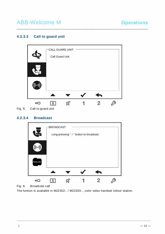
ABB-Welcome M Operations
| — 12 —
4.2.3.3 Call to guard unit
Fig. 5: Call to guard unit
4.2.3.4 Broadcast
Fig. 6: Broadcast callThe funtion is available in M22302-. / M22303-., color video handset indoor station.
CALL GUARD UNIT
Call Guard Unit
BROADCAST
Long-pressing “√“ button to broadcast

ABB-Welcome M Operations
| — 13 —
4.2.3.5 Switch actuator
Fig. 7: Switch actuator
Set the actuator list in the “system settings-switch actuator“ menu first.After chosing a list, press button √ to enable the lock or light which is connected with theswitch actuator.
SWITCH ACTUATOR
Actuator 1 (001)
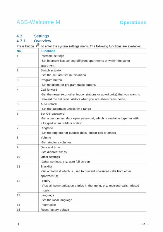
ABB-Welcome M Operations
| — 14 —
4.3 Settings4.3.1 OverviewPress button to enter the system settings menu. The following functions are available:No. Functions1 Intercom settings
-Set intercom lists among different apartments or within the sameapartment
2 Switch actuator-Set the actuator list in this menu
3 Program button-Set functions for programmable buttons
4 Call forward-Set the target (e.g. other indoor stations or guard units) that you want to forward the call from visitors when you are absent from home.
5 Auto unlock-Set the automatic unlock time range
6 Set OS password-Set a customized door open password, which is available together witha keypad at an outdoor station.
7 Ringtone-Set the ringtone for outdoor bells, indoor bell or others
8 Volume-Set ringtone volumes
9 Date and time-Set different times.
10 Other settings-Other settings, e.g. auto full screen
11 Blacklist-Set a blacklist which is used to prevent unwanted calls from otherapartment(s)
12 History-View all communication entries in the menu, e.g. received calls, missed
calls,
13 Language-Set the local language
14 Information
15 Reset factory defaultPos: 27 /Di nA4 - A nleitu ngen Onlin e/Ueb ersc hrift en/3 ./Spr ech- und Videov erbi ndu ng @ 20\ mod _13 232 6236 870 0_1 5.do cx @ 1119 27 @ 3 @ 1
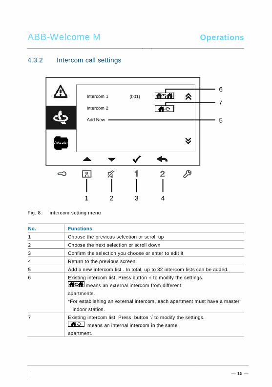
ABB-Welcome M Operations
| — 15 —
4.3.2 Intercom call settings
Fig. 8: intercom setting menu
No. Functions1 Choose the previous selection or scroll up
2 Choose the next selection or scroll down
3 Confirm the selection you choose or enter to edit it
4 Return to the previous screen
5 Add a new intercom list . In total, up to 32 intercom lists can be added.
6 Existing intercom list: Press button √ to modify the settings. means an external intercom from different
apartments.*For establishing an external intercom, each apartment must have a master
indoor station.
7 Existing intercom list: Press button √ to modify the settings. means an internal intercom in the same
apartment.
1 2 3
6
4
5
Intercom 1 (001)
Intercom 2
Add New
7

ABB-Welcome M Operations
| — 16 —
Add a new list
Fig. 9: Add new intercom
No. Functions1 Enter to choose the call type :
-an external intercom means a call from different apartments-an internal intercom means a call within the same apartment
2 Enter to change the target address, from 001 to 250.*If the call type is the internal intercom, there is no need to set the targetaddress.
3 Rename the intercom list:Scroll through letters of the alphabet or numbers one by one with “+” or“-” button
After setting, press “Save” for confirmation.
1Call Type External Intercom
Target Address
Rename 3
INTERCOM
001
mike
Save Cancel
2

ABB-Welcome M Operations
| — 17 —
4.3.3 Switch actuator settings
Fig. 10: Switch actuator settings
No. Functions1 Existing switch actuator list: Press button √ to modify the settings.2 Add a new actuator list:Totally, up to 10 switch actuator lists can be added.
3 Enter to change target address with “+” or “-” button from 001 to 199.
3 Rename the switch actuator list:Scroll through letters of the alphabet or numbers one by one with “+” or “-” button
3
4
SWITCH ACTUATOR
Actuator 1 (001)
Add New
Target Address
Rename
002
light
Save Cancel
SWITCH ACTUATOR
2
1
Add a new list

ABB-Welcome M Operations
| — 18 —
4.3.4 Program button settings
Fig. 11: Program button settings
No. Functions1 Set functions for the program button, e.g. releasing 2nd-lock, calling guard
unit, intercom call, enabling the switch actuator.*2nd-lock means the lock is connected with an outdoor station (NC-NO-COM)*Only the existing intercom call list & switch actuator list can be assignedto the program button.
Button 1 Release 2nd-Lock
PROGRAM BUTTON
Button 2 None
1

ABB-Welcome M Operations
| — 19 —
4.3.5 Call forward settings
Fig. 12: Call forward settings
No. Functions1 Enable/disable the call forward function.
2 Enter to choose a call type, including indoor or guard unit.
3 Enter to change the target address if the call type is an indoor station.*If the call forward function is activated, the auto unlock function will be disabled.*The function only can be set in the master indoor station*The funtion is available in M22302-. / M22303-., color video handset indoor station.
1
2
Call Forward
Call Type
√
Indoor
Save Cancel
CALL FORWARD
Target Address 001 31

ABB-Welcome M Operations
| — 20 —
4.3.6 Auto unlock settings
Fig. 13: Auto unlock settings
No. Functions1 Enable/disable the auto unlock function.
2 Enable/disable the auto unlock during Time 1.
3 Set starting time and ending time for Time 1
4 Enable/disable auto unlock during Time 2.
5 Set starting time and ending time for Time 2.*If you activate the auto unlock function without setting exact working time, this function will beavailable for 10 hours.*If the auto unlock function is activated, the call forward function will be disabled.*The function only can be set in master indoor station.
1Auto Unlock
Time 1
2
AUTO UNLOCK
√
√
08 00
17 00
:
:
Time 2 X
00 00
00 00
:
:
4
35
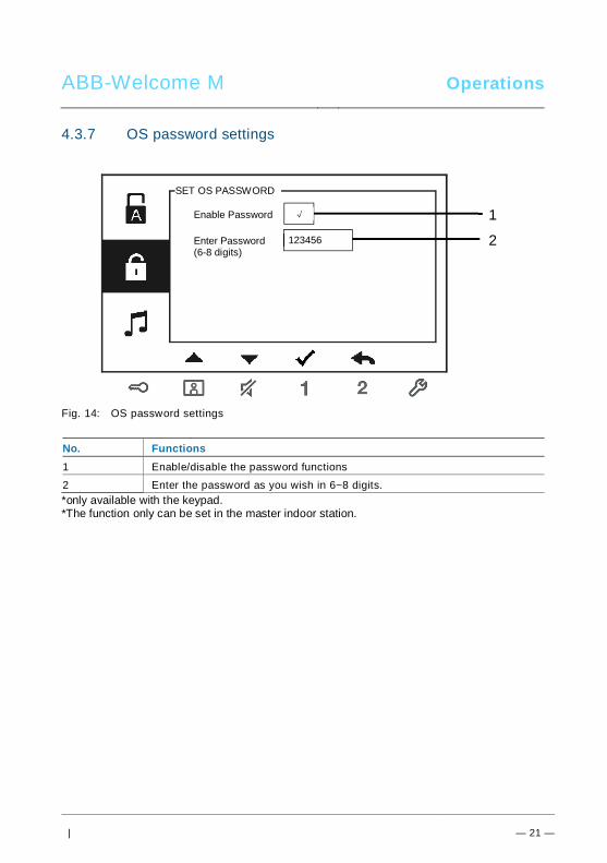
ABB-Welcome M Operations
| — 21 —
4.3.7 OS password settings
Fig. 14: OS password settings
No. Functions1 Enable/disable the password functions
2 Enter the password as you wish in 6~8 digits.*only available with the keypad.*The function only can be set in the master indoor station.
1Enable Password
Enter Password(6-8 digits)
SET OS PASSWORD
√
123456 2

ABB-Welcome M Operations
| — 22 —
4.3.8 Ringtone settings
Fig. 15: Ringtone
No. Functions1 Select the bell sound for the default outdoor station.
2 Select the bell sound for other outdoor stations.
3 Select the bell sound for the apartment door.
4 Select the bell sound for others, e.g.a call from the guard unit, or anintercom call from other apartments.
1Default Outdoor
Other Outdoors
RING TONE
Ring Tone 1
Ring Tone 2 2
Doorbell Ring Tone 3
Others Ring Tone 4
3
4

ABB-Welcome M Operations
| — 23 —
4.3.9 Volume settings
Fig. 16: Volume settings
No. Functions1 Set the volume of bell sound.
2 Enable/disable the feedback tone which sounds when the touch button ispressed.
1Ringtone Volume
Touchbutton Tone
VOLUME
Volume 3
2√

ABB-Welcome M Operations
| — 24 —
4.3.10 Date and time settings
Fig. 17: Date and time settings
No. Functions1 Set the date.
2 Set the time.
3 Enable/disable the summer time function.*The funtion is available in M22302-. / M22303-., color video handset indoor station.
1Date(YYYY-MM-DD)
Time
DATE AND TIME
2013
208
Summer Time √
: 00
- 01 - 01
3

ABB-Welcome M Operations
| — 25 —
4.3.11 Door entry system settings
Fig. 18: Door entry system settings
No. Functions1 Enable/disable the auto full screen function.
2 Enable/disable the auto-snapshot function.*The funtion is available in M22302-. / M22303-., color video handset
indoor station.
3 Enable/disable the door status check function(only available on conditionthat the sensor is installed with an outdoor station; flashes when thedoor is open).
4 Enable/disable the missed call function( flashes when there is a missedcall).*The funtion is available in M22302-. / M22303-., color video handset
indoor station.
1Auto Full Screen
Auto-snapshots
DOOR ENTRY SYSTEM
2
Door Status Check
√
3
Missed
√
√
√ 4

ABB-Welcome M Operations
| — 26 —
4.3.12 Blacklist settings
Fig. 19: Blacklist settings
No. Functions1 The existed black list. Press √ button to modify the setting.
2 Add a new black list. Totally, up to 32 black lists can be added.
3 Enter to change target address with “+” or “-” button from 001 to 250.*The function only can be set in the master indoor station.*The funtion is available in M22302-. / M22303-., color video handset indoor station.
Blacklist 1
Add New
BLACKLIST
(001)
Target Address
BLACKLIST
Save Cancel
002
1
2
3

ABB-Welcome M Operations
| — 27 —
4.3.13 History review
Fig. 20: History review
No. Functions1 Up to 100 events can be recorded in the history menu.
-If the snapshot function is enabled, an icon is diplayed.If no snapshotfunction, the icon is not displayed..
-Date, time and type of the event are recorded together with the snapshot.- Directions: means dialing calls means receiving calls means missed calls
●
HISTORY
1/2Outdoor -1
1/632013-03-2116:45
Outdoor - 1
● 2013-03-2116:45
Outdoor - 1
● 2013-03-2114:24
Outdoor - 1
1
2
3

ABB-Welcome M Operations
| — 28 —
2 Press this button to view details of this event.Two pictures are always made when a visitor rings the bell.
3 Press this button to delete a record item*The funtion is available in M22302-. / M22303-., color video handset indoor station.

ABB-Welcome M Operations
| — 29 —
4.3.14 Language settings
Fig. 21: Language settings
4.3.15 Information
Fig. 22: Information of the indoor station (scanning the QR code to get the detailedinstruction of the indoor station)
English
LANGUAGE
Française
Italiano
Português
Español
Flash Version: V0.11_130723
INFORMATION
MCU Version: V0.11_130722
M/S: Master
Default Outdoor: 1
Indoor St. Add.: 001

ABB-Welcome M Operations
| — 30 —
4.3.16 Reset factory default
Fig. 23: Reset factory default
No. Functions1 Reset all settings:
Reset the device and restore all default configurations. The operationdoes not delete the programmed data and history, such as intercom listsand switch actuator lists.
2 Clear all data:Delete all programmed data and history. Also all configurations will berestored to factory default settings.
RESET FACTORY DEFAULT
Are you sure to reset?
Cancel OK
Reset All Settings
Clear All Data ×
√

ABB-Welcome M Operations
| — 31 —
Pos: 67 /Di nA4 - A nleitu ngen Onlin e/Ueb ersc hrift en/2 ./Reini gung @ 1 9\m od_ 131 0733 980 533 _15. docx @ 10 785 3 @ 2 @ 1
4.4 CleaningPos: 68 /Di nA4 - A nleitu ngen Onlin e/In halt/KNX/Do orEnt ry/Reini gun g/Reini gun g Touchsc ree nm onito r @ 19\m od_ 131 073 410 897 8_15 .docx @ 1 078 62 @ @ 1
CautionRisk of damage to the screen surface.The screen surface can be damaged by hard or sharp objects!Never use such objects for entries on the touch screen monitor.– Use your finger or a plastic stylus.
The screen surface can be damaged by cleaning fluids or abrasiveagents!– Clean the surfaces using a soft cloth and commercially available
glass cleaner.– Never use abrasive cleaning agents.
Pos: 69 /B usch-J aeg er (Neus truk tur )/M odul -Strukt ur/O nline -Doku me ntatio n/Steu er mod ule - Onlin e-Dok ume ntati on ( -- > Für alle Dok ume nte <- -)/ +++ ++ ++ +++ ++ S eiten umb ruch + +++ ++ ++ +++ + @ 9\m od_ 126 8898 668 093 _0. docx @ 521 49 @ @ 1

ABB-Welcome M Operations
| — 32 —
Pos: 70 /Di nA4 - A nleitu ngen Onlin e/Ueb ersc hrift en/2 ./Ge raet eeins tellun gen @ 1 8\mo d_1 302 768 847 744 _15. docx @ 10 354 8 @ 2 @ 1
4.5 Adjusting the devicePos: 71 /Di nA4 - A nleitu ngen Onlin e/Ueb ersc hrift en/3 ./Abschl usswide rsta nd @ 19\ mod _13 219 5807 990 6_1 5.do cx @ 1100 83 @ 3 @ 1
Pos: 72 /Di nA4 - A nleitu ngen Onlin e/In halt/KNX/Do orEnt ry/Bedie nun g/Abschl usswide rsta nd s etzen 83 220 -AP-xxx @ 19\ mod _13 1072 339 236 9_1 5.do cx @ 1 078 41 @ @ 1
Fig. 24:Pos: 74 /Di nA4 - A nleitu ngen Onlin e/In halt/KNX/Do orEnt ry/Bedie nun g/M aste r/Slave Sc halte r setz en 832 20-AP-xxx @ 1 9\m od_1 310 723 320 966 _15. docx @ 10 783 3 @ @
1. StationJumper to set the address of default outdoor station.
2. X100 X10 X1Jumper to set the address of the indoor station.EXAMPLE: setting address 024.
3. Master /Slave functionOnly one indoor station in each apartment must be set as "Master" (Jumper shouldbe set as 'M/S on'). All additional indoor stations in the same apartment must beset as "Slave" (Jumper should be set as 'M/S off').
4. Terminal resistorIn video installations or mixed audio and video installations, the Jumper must beset as 'RC on' on the last device of the line.
5. a b = Bus connection= Door bell connection
DC GND = Additional power supplyPos: 75 /B usch-J aeg er (Neus truk tur )/M odul -Strukt ur/O nline -Doku me ntatio n/Steu er mod ule - Onlin e-Dok ume ntati on ( -- > Für alle Dok ume nte <- -)/ +++ ++ ++ +++ ++ S eiten umb ruch + +++ ++ ++ +++ + @ 9\m od_ 126 8898 668 093 _0. docx @ 521 49 @ @ 1

ABB-Welcome M Technical data
| — 33 —
Pos: 76 /Di nA4 - A nleitu ngen Onlin e/Ueb ersc hrift en/1 ./Technisc he D aten @ 18 \mo d_1 302 615 863 001 _15. docx @ 10 341 6 @ 1 @ 1
5 Technical dataPos: 77 /Di nA4 - A nleitu ngen Onlin e/In halt/KNX/Do orEnt ry/83 220 -AP-xxx/ Tech nische Date n - 832 20-AP-x xx @ 1 8\m od_ 130 321 285 4559 _15 .docx @ 1 037 05 @ @ 1
Designation ValueDisplay resolution: 480 x 272
Display size: 4.3”
Operating temperature -10° C - +55° C
Storage temperature -40° C – +70° CProtection IP 30
Single-wire clamps 2 x 0.28 mm² – 2 x 1 mm²
Fine-wire clamps 2 x 0.28 mm² – 2 x 1 mm²
Bus voltage 20-30 V
Pos: 78 /B usch-J aeg er (Neus truk tur )/M odul -Strukt ur/O nline -Doku me ntatio n/Steu er mod ule - Onlin e-Dok ume ntati on ( -- > Für alle Dok ume nte <- -)/ +++ ++ ++ +++ ++ S eiten umb ruch + +++ ++ ++ +++ + @ 9\m od_ 126 8898 668 093 _0. docx @ 521 49 @ @ 1

ABB-Welcome M Mounting / Installation
| — 34 —
Pos: 79 /B usch-J aeg er (Neus truk tur )/M odul -Strukt ur/O nline -Doku me ntatio n/Übe rsch rifte n ( --> Fü r alle Doku men te < -- )/1. E bene /M - O/ Mont age / Ins tallatio n @ 18\ mod _13 0261 396 611 1_1 5.do cx @ 1 033 73 @ 1 @ 1
6 Mounting / InstallationPos: 80 /B usch-J aeg er (Neus truk tur )/M odul -Strukt ur/O nline -Doku me ntatio n/Siche rheit (- -> Fü r alle D oku ment e < --) /War nhinweis e/Siche rheit - Nie ders pan nun gs- und 230 V-Leit ung en @ 18\ mod _13 026 178 214 91_1 5.d ocx @ 103 465 @ @ 1
WarningElectric voltage!Risk of death and fire due to electrical voltage of 100-240 V.– Low-voltage and 100-240 V cables must not be installed together in
a flush-mounted socket!In case of a short-circuit there is the danger of a 100-240 V load onthe low-voltage line.
Pos: 81 /B usch-J aeg er (Neus truk tur )/M odul -Strukt ur/O nline -Doku me ntatio n/Siche rheit (- -> Fü r alle D oku ment e < --) /War nhinweis e/Siche rheit - Fachk enn tnisse @ 18 \mo d_1 302 774 384 017_ 15. docx @ 10 356 4 @ 2 @ 1
6.1 Requirements for the electrician
WarningElectric voltage!Install the device only if you have the necessary electrical engineeringknowledge and experience.• Incorrect installation endangers your life and that of the user of the
electrical system.• Incorrect installation can cause serious damage to property, e.g.
due to fire.The minimum necessary expert knowledge and requirements for the
installation are as follows:• Apply the "five safety rules" (DIN VDE 0105, EN 50110):
1. Disconnect from power;2. Secure against being re-connected;3. Ensure there is no voltage;4. Connect to earth;5. Cover or barricade adjacent live parts.
• Use suitable personal protective clothing.• Use only suitable tools and measuring devices.• Check the type supply network (TN system, IT system, TT system)
to secure the following power supply conditions (classic connectionto ground, protective earthing, necessary additional measures,etc.).
Pos: 82 /Di nA4 - A nleitu ngen Onlin e/In halt/KNX/Do orEnt ry/M onta ge/ Mont age hinweis e - Allg emei n @ 1 9\m od_ 131 056 367 047 8_15 .docx @ 1 077 43 @ 2 @ 1

ABB-Welcome M Mounting / Installation
| — 35 —
6.2 General installation instructions• Terminate all branches of the wiring system via a connected bus device (e.g.,
indoor station, outdoor station, system device).• Do not install the system controller directly next to the bell transformer and other
power supplies (to avoid interference).• Do not install the wires of the system bus together with 100-240 V wires.• Do not use common cables for the connecting wires of the door openers and wires
of the system bus.• Avoid bridges between different cable types.• Use only two wires for the system bus in a four-core or multi-core cable.• When looping, never install the incoming and outgoing bus inside the same cable.• Never install the internal and external bus inside the same cable.Pos: 83 /B usch-J aeg er (Neus truk tur )/M odul -Strukt ur/O nline -Doku me ntatio n/Steu er mod ule - Onlin e-Dok ume ntati on ( -- > Für alle Dok ume nte <- -)/ +++ ++ ++ +++ ++ S eiten umb ruch + +++ ++ ++ +++ + @ 9\m od_ 126 8898 668 093 _0. docx @ 521 49 @ @ 1

ABB-Welcome M Mounting / Installation
| — 36 —
Pos: 84 /B usch-J aeg er (Neus truk tur )/M odul -Strukt ur/O nline -Doku me ntatio n/Übe rsch rifte n ( --> Fü r alle Doku men te < -- )/2. E bene /M - O/ Mont age @ 1 8\m od_1 302 615 960 458 _15. docx @ 10 342 4 @ 2 @ 1
6.3 MountingPos: 85. 1 /DinA4 - Anleit ung en O nline/I nhal t/KNX/DoorE ntry/ 832 20-AP-xxx /Mo nta ge - Mo dule/ Mon tag e - Mon tage dos e -- 83 220 -AP-xxx @ 19\ mod _132 325 040 684 8_1 5.doc x @ 1 110 98 @ @ 1
Recommended installation height
Dismantling
Open the housing of the panel by pulling the clamp at the bottom of the device.
Installation dimension

ABB-Welcome M Mounting / Installation
| — 37 —
1. The bottom of the device has screw holes for fastening on the wall according to theabove dimension instructions.
2. In addition, the bottom of the device can be fixed to the existing flush-mounted box.The dimension of the compatible flush-mounted box is shown in graphics above.
Wiring
Fix the bottom of the device and connect it in accordance with the graphics. Theinsulated section of the cable end must not be longer than 10mm.
SettingsSet addresses of the preferred outdoor stations and the address of the indoor station onthe jumper (see chapter " Adjusting the device ").

ABB-Welcome M Mounting / Installation
| — 38 —
Mounted on the wall
1. Fix the bottom of the device to the wall.2. Latch the upper part of the device onto its bottom part.; place the upper side of the
device on the lock-in lugs and then press the bottom side onto the bottom part ofthe device until it is caught by the clamp.
Mounted with flush-mounted box
1. Fix the bottom of the device to the existing flush-mounted box.2. Latch the upper part of the device onto its bottom part;place the upper side of the
device on the lock-in lugs and then press the bottom side onto the bottom part ofthe device until it is caught by the clamp.

ABB-Welcome M Mounting / Installation
| — 39 —
Mounted with desktop bracket
1. Fix the bottom of the device to the desktop bracket.2. Latch the upper part of the device onto its bottom part;place the upper side of the
device on the lock-in lugs and then press the bottom side onto the bottom part ofthe device until it is caught by the clamp.
The installation of the indoor station is now complete.
Pos: 94 /B usch-J aeg er (Neus truk tur )/M odul -Strukt ur/O nline -Doku me ntatio n/Steu er mod ule - Onlin e-Dok ume ntati on ( -- > Für alle Dok ume nte <- -)/ +++ ++ ++ +++ ++ S eiten umb ruch + +++ ++ ++ +++ + @ 9\m od_ 126 8898 668 093 _0. docx @ 521 49 @ @ 1

ABB-Welcome M Mounting / Installation
Pos: 95 /Di nA4 - A nleitu ngen Onlin e/In halt/KNX/Do orEnt ry/Proj ektier ung -M erkbl att/Pr ojektie rPos: 9 7 /Busc h-Ja ege r (N eust ruktu r)/ Mo dul-Str uktu r/Onli ne-D oku ment ation /Rückseit en (-- > Für alle Dok um ente <- -)/R ückseit e - Bus ch-J aeg er - Allgem ein @ 20\ mod _13 273 200 748 86_1 5.d ocx @ 137 103 @ @ 1
Notice=== E nde der Liste für Tex tma rke Ba ckcove r = ==
We reserve the right to at all times make technical changes as well as changes in thecontents of this document without prior notice.The detailed specifications agreed to at the time of ordering apply to all orders. ABBaccepts no responsibility for possible errors or incompleteness in this document. We reserve all rights to this document and the topics and illustrations contained therein.The document and its contents, or extracts thereof, must not be reproduced, transmittedor reused by third parties without prior written consent by ABB.

VER:1.0 │ 02.06.2014
ABB-Welcome M
Pos: 2 /DinA4 - Anl eitun gen Online /Inh alt/KNX/Doo rEntry /832 20-AP- xxx/Tit elblat t - 832 20-AP-xxx - ABB @ 1 9\m od_ 132 3249 806 476 _15. docx @ 11 108 4 @ @ 1
WM1601
WM1602
WM1603
Moniteur vidéo intérieur
avec combiné et écran 4.3"
=== E nde der Liste für Tex tma rke C over == =
ABB-Welcome M WM160x
— 2 —
Pos: 4 /Busc h-Ja ege r (N eust rukt ur)/ Mo dul-St ruktu r/Onli ne-D oku ment ation /Inh altsve rzeich nis ( --> Fü r alle Doku men te <-- )/In haltsve rzeic hnis @ 19\ mod _13 206 490 4438 6_1 5.d ocx @ 109 653 @ @ 1
1 Sécurité .................................................................................................... 42 Usage prévu ............................................................................................. 43 Environnement .......................................................................................... 4
3.1 Appareils ABB ........................................................................... 54 Opérations ................................................................................................ 6
4.1 Fonctionnement normal ............................................................. 64.1.1 Éléments de commande ............................................................ 64.2 Commandes ............................................................................. 94.2.1 Appel entrant / Pendant un appel ............................................... 94.2.2 Réglages de l'écran et du volume pendant les appels............... 114.2.3 Menu Communication ............................................................. 124.3 Paramètres ............................................................................. 164.3.1 Présentation ........................................................................... 164.3.2 Réglages des appels intercom ................................................. 174.3.3 Réglages du relais actionneur.................................................. 204.3.4 Réglages des touches programmables .................................... 224.3.5 Réglages du transfert d'appels................................................. 234.3.6 Réglages du déverrouillage auto.............................................. 244.3.7 Réglages du code de la platine de rue ..................................... 254.3.8 Réglages de la sonnerie .......................................................... 264.3.9 Réglages du volume................................................................ 274.3.10 Réglages de la date et de l'heure ............................................. 284.3.11 Réglages des options .............................................................. 294.3.12 Réglages de la liste noire ........................................................ 304.3.13 Consultation de l'historique ...................................................... 324.3.14 Réglages de la langue ............................................................. 344.3.15 Informations ............................................................................ 354.3.16 Restauration des réglages d'usine par défaut ........................... 364.4 Nettoyage ............................................................................... 374.5 Réglage de l'appareil ............................................................... 38
5 Caractéristiques techniques ..................................................................... 406 Montage / Installation .............................................................................. 41
6.1 Exigences à l'égard de l'électricien........................................... 42

ABB-Welcome M WM160x
— 3 —
6.2 Consignes d'installation générales ........................................... 436.3 Montage ................................................................................. 44
=== E nde der Liste für Tex tma rke TOC == =

ABB-Welcome M WM160x
— 4 —
Pos: 6 /Busc h-Ja ege r (N eust rukt ur)/ Mo dul-St ruktu r/Onli ne-D oku ment ation /Übe rschri ften (- -> Für alle D okum ent e < --)/ 1. Eb ene/S - T /Sicher heit @ 18\ mod _13 026 127 917 90_ 15.d ocx @ 103 357 @ 1 @ 1
1 SécuritéPos: 7 /Busc h-Ja ege r (N eust rukt ur)/ Mo dul-St ruktu r/Onli ne-D oku ment ation /Sicher heit (-- > Für alle Dok um ente <- -)/Wa rn hinweise /Sicher heit - 23 0 V @ 18\m od_ 130 260 681 675 0_15 .docx @ 1 033 08 @ @ 1
Avertissement
Tension électrique !
Danger de mort et d'incendie en raison de la présence d'une tension électriquede 100-240 V.– Les travaux sur le système d'alimentation 100-240 V peuvent uniquement
être effectués par des électriciens autorisés !– Débrancher l'alimentation secteur avant l'installation et/ou le démontage !
Pos: 8 /Busc h-Ja ege r (N eust rukt ur)/ Mo dul-St ruktu r/Onli ne-D oku ment ation /Übe rschri ften (- -> Für alle D okum ent e < --)/ 1. Eb ene/A - F /Bestim mun gsge mä ßer Geb rau ch @ 18\ mod _13 027 6332 131 6_1 5.do cx @ 1034 83 @ 1 @ 1
2 Usage prévuPos: 9 /DinA4 - Anl eitun gen Online /Inh alt/KNX/Doo rEntry /832 20-AP- xxx/Besti mmu ngsg em aesse r Ge bra uch - 83 220 -AP-xxx- 500 @ 2 0\mo d_1 324 561 168 699 _15. docx @ 11 272 8 @ @ 1
Le WM16xx fait partie intégrale du système ABB Welcome M et fonctionne exclusivementavec des composants de ce système. L'appareil doit uniquement être installé dans des locauxintérieurs secs.
Pos: 10 /B usch-J aeg er (Neus truk tur )/M odul -Strukt ur/O nline -Doku me ntatio n/Übe rsch rifte n ( --> Fü r alle Doku men te < -- )/1. E bene /U - Z/U mwelt @ 18\ mod _13 026 141 5896 7_1 5.d ocx @ 103 383 @ 1 @ 1
3 EnvironnementPos: 11 /B usch-J aeg er (Neus truk tur )/M odul -Strukt ur/O nline -Doku me ntatio n/Umw elt ( --> Für all e Doku me nte <-- )/Hinweis e/Hinw eis - U mwelt - Hinweis Elektr oge räte @ 1 8\mo d_1 302 763 973 434 _15. docx @ 10 350 0 @ @ 1
Prendre en compte la protection de l'environnement !
Les appareils électriques et électroniques usagés ne doivent pas êtreéliminés avec les ordures ménagères.– L'appareil contient des matières premières de valeur qui peuvent être
recyclées. Par conséquent, l'élimination de l'appareil doit se faire dansun centre de collecte approprié.
Pos: 12 /Di nA4 - A nleitu ngen Onlin e/Ueb ersc hrift en/2 ./ABB Gera ete @ 19 \mo d_1 323 162 843 832_ 15. docx @ 11 087 5 @ 2 @ 1

ABB-Welcome M WM160x
— 5 —
3.1 Appareils ABBPos: 13 /B usch-J aeg er (Neus truk tur )/M odul -Strukt ur/O nline -Doku me ntatio n/Umw elt ( --> Für all e Doku me nte <-- )/Hinweis e/Hinw eis - U mwelt - ABB Elektro ger äte @ 19\ mo d_1 3231 627 458 39_ 15.d ocx @ 110 867 @ @ 1
Tous les matériaux d'emballage et appareils ABB portent les marquages et sceaux d'essaipour une élimination correcte. Il faut toujours éliminer les matériaux d'emballage et lesproduits électriques ainsi que leurs composants via des centres de collecte et entreprisesagréés.Les produits ABB sont conformes aux exigences légales, et aux lois régissant les appareilsélectroniques et électriques et au règlement REACH.(Directive européenne 2002/96/CE DEEE et 2002/95/CE RoHS)(Règlement REACH et loi sur l'application du règlement (CE) n°1907/2006)

ABB-Welcome M WM160x
— 6 —
Pos: 18 /Di nA4 - A nleitu ngen Onlin e/Ueb ersc hrift en/1 ./Bedie nun g @ 18\m od_ 130 261 392 416 5_15 .docx @ 1 033 65 @ 1 @ 1
4 OpérationsPos: 19 /Di nA4 - A nleitu ngen Onlin e/Ueb ersc hrift en/2 ./Nor male r Bet rieb @ 18 \mo d_1 302 768 8209 65_ 15. docx @ 10 3540 @ 2 @ 1
4.1 Fonctionnement normalPos: 20 /Di nA4 - A nleitu ngen Onlin e/Ueb ersc hrift en/3 ./Bedie nele men te @ 20\ mod _13 232 6022 055 9_1 5.do cx @ 1 116 47 @ 3 @ 1
4.1.1 Éléments de commandePos: 21 /Di nA4 - A nleitu ngen Onlin e/In halt/KNX/Do orEnt ry/83 220 -AP-xxx/Be dienel eme nte - 8 322 0-AP-xxx @ 18\ mo d_1 3032 128 536 05_ 15.d ocx @ 103 673 @ @ 1
Fig. 1 Éléments de commande
12
3
9
4 5 6 7 8

ABB-Welcome M WM160x
— 7 —
N° Fonctions1 Combiné
1A Lors d'un appel, décrocher le combiné pour activer la communicationdans un délai de 30 secondes, puis raccrocher le combiné pour mettre finà l'appel.
1B En mode veille, soulever le combiné pour accéder au menucommunication.
2 Écran 4.3"2A WM1601 , avec écran N/B.2B WM1602 / WM1603 avec écran couleur.
3 Bouton de déverrouillage3A Ouvrir la porte en appuyant sur ce bouton à tout moment.3B Déverrouillage auto : la porte est automatiquement ouverte lors d'un appel
entrant (pour cette fonction, maintenir ce bouton enfoncé pendant plus de 10secondes jusqu'à ce que la LED rétro-éclairée soit allumée, cette mêmeopération désactive la fonction et la LED est éteinte).
La LED clignote lentement, ceci indique qu'un appel entrant est en cours.La LED s'allume, ceci indique que le déverrouillage auto est activé.La LED clignote rapidement, ceci indique que le système est occupé ou que laporte est restée ouverte au-delà du temps prédéfini (le capteur doit d'abord êtreconnecté).
4 Bouton de surveillance4A En mode veille, appuyer sur ce bouton pour accéder à la caméra de la
platine de rue par défaut.4B Lorsque l'écran est allumé, appuyer sur ce bouton pour accéder à la
platine de rue suivante. (La fonction est disponible selon le typed'installation)
4C **Lorsque l'écran est allumé, maintenir ce bouton pour effectuer unecapture d'écran manuellement.
4D **En mode veille, si la LED clignote, appuyer sur ce bouton pourafficher le menu « Historique ».
**La LED clignote lentement pour indiquer un appel en absence.5 Bouton silence
5A En mode veille, appuyer sur ce bouton pour couper la sonnerie du

ABB-Welcome M WM160x
— 8 —
moniteur intérieur.5B En mode veille, appuyer longuement sur le bouton pour couper le son
de la sonnerie de tous les moniteurs intérieurs dans l'appartement.5C Lors d'un appel, appuyer sur ce bouton pour rejeter l'appel.5D Pendant la conversation, appuyer sur ce bouton pour couper le son du
microphone.La LED s'allume pour indiquer le mode silence.
6 Bouton programmable 16A Déverrouiller la serrure connectée à un moniteur intérieur (COM-NC-NO)
(fonction par défaut).6B En mode veille, appuyer longuement sur ce bouton pendant 3 secondes
pour envoyer une alarme SOS à l'interface gardien. La LED clignotelentement pour indiquer que l'opération a réussi et clignote rapidement pourindiquer qu'elle a échoué.
6C *Programmable pour une fonction supplémentaire, ex. : appel de l'interfacegardien, intercom, etc.
7 Bouton programmable 2*Programmable pour une fonction supplémentaire, ex. : appel de l'interface
gardien, interphone, etc.
8 Bouton de configuration du systèmePermet d'accéder au menu de configuration du système pour les diverses
fonctions de l'appareil.La LED clignote rapidement, cela indique que le système est occupé.
9 ***Fonction boucle inductive*Pour plus de détails, veuillez contacter votre électricien.
** La fonction est disponible dans WM1602 / WM1603, moniteur intérieur avec écran vidéo couleur.
*** La fonction est uniquement disponible dans WM1603.Pos: 22 /B usch-J aeg er (Neus truk tur )/M odul -Strukt ur/O nline -Doku me ntatio n/Steu er mod ule - Onlin e-Dok ume ntati on ( -- > Für alle Dok ume nte <- -)/ +++ ++ ++ +++ ++ S eiten umb ruch + +++ ++ ++ +++ + @ 9\m od_ 126 8898 668 093 _0. docx @ 521 49 @ @ 1

ABB-Welcome M WM160x
— 9 —
Pos: 26 /Di nA4 - A nleitu ngen Onlin e/Ueb ersc hrift en/2 ./Bedie nakti onen @ 2 0\m od_ 1323 262 294 281 _15. docx @ 11 191 1 @ 2 @ 1
4.2 CommandesPos: 27 /Di nA4 - A nleitu ngen Onlin e/Ueb ersc hrift en/3 ./Spr ech- und Videov erbi ndu ng @ 20\ mod _13 232 6236 870 0_1 5.do cx @ 1119 27 @ 3 @ 1
4.2.1 Appel entrant / Pendant un appelPos: 28 /Di nA4 - A nleitu ngen Onlin e/In halt/KNX/Do orEnt ry/83 220 -AP-xxx/Sp rech - u nd Vide over bind ung - 8 322 0-AP-xxx @ 20\ mo d_1 3232 623 418 52_ 15.d ocx @ 111 919 @ @ 1
Fig. 2 Appel entrant / Pendant un appel
Lors d'un appel, les fonctions suivantes sont disponibles :N° Fonctions1 Soulever le combiné pour accepter l'appel entrant ; pendant un appel,
raccrocher le combiné pour mettre fin à l'appel.
2 Appuyer sur ce bouton pour ouvrir la porte d'où provient l'appel.
3-A Appuyer sur ce bouton pour accéder à la caméra auxiliaire de la platine derue s'il y en a une.
3-B Appuyer sur ce bouton pour prendre une photo.*La fonction est disponible dans WM1602 / WM1603, moniteur intérieur
avec écran vidéo couleur.
4 Appuyer sur ce bouton pour couper le son d'un appel entrant. Pendant unappel, appuyer sur ce bouton pour couper le son du microphone.
30s
Outdoor 1
2 4 6
7
8
3 51
ABB-Welcome M WM160x
— 10 —
5-A Appuyer sur ce bouton pour activer la fonction du bouton programmable.
5-B Si la fonction « Commande 2nd contact (COM-NC-NO) » ou « Commanderelais actionneur » est assignée au bouton programmable, appuyer surce bouton pour activer la fonction.
6-A6-B
Appuyer sur ce bouton pour activer ou désactiver la fonction plein écran.
Maintenir ce bouton enfoncé pour accéder au menu de réglage de laluminosité.
7 Temps restant de communication restant.
8 Nombre de platines de ruePos: 29 /B usch-J aeg er (Neus truk tur )/M odul -Strukt ur/O nline -Doku me ntatio n/Steu er mod ule - Onlin e-Dok ume ntati on ( -- > Für alle Dok ume nte <- -)/ +++ ++ ++ +++ ++ S eiten umb ruch + +++ ++ ++ +++ + @ 9\m od_ 126 8898 668 093 _0. docx @ 521 49 @ @ 1
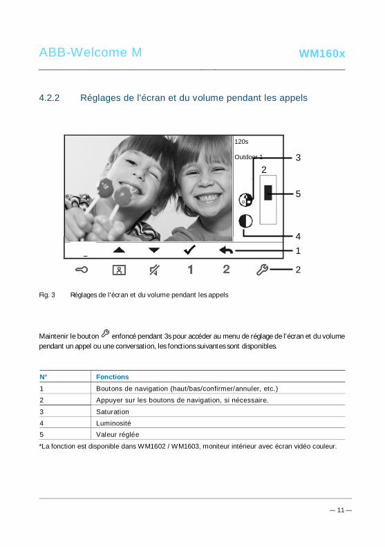
ABB-Welcome M WM160x
— 11 —
Pos: 30 /Di nA4 - A nleitu ngen Onlin e/Ueb ersc hrift en/3 ./Tuer oeff nen @ 2 0\mo d_1 323 263 277 453 _15. docx @ 11 193 5 @ 3 @ 1
4.2.2 Réglages de l'écran et du volume pendant les appelsPos: 31 /Di nA4 - A nleitu ngen Onlin e/In halt/KNX/Do orEnt ry/83 220 -AP-xxx/ Tue r o effne n - 832 20-AP-x xx @ 20\m od_ 132 326 795 847 9_15 .docx @ 1 121 09 @ @ 1
Fig. 3 Réglages de l'écran et du volume pendant les appels
Maintenir le bouton enfoncé pendant 3s pour accéder au menu de réglage de l'écran et du volumependant un appel ou une conversation, les fonctions suivantes sont disponibles.
N° Fonctions1 Boutons de navigation (haut/bas/confirmer/annuler, etc.)
2 Appuyer sur les boutons de navigation, si nécessaire.
3 Saturation
4 Luminosité5 Valeur réglée
*La fonction est disponible dans WM1602 / WM1603, moniteur intérieur avec écran vidéo couleur.
Pos: 32 /B usch-J aeg er (Neus truk tur )/M odul -Strukt ur/O nline -Doku me ntatio n/Steu er mod ule - Onlin e-Dok ume ntati on ( -- > Für alle Dok ume nte <- -)/ +++ ++ ++ +++ ++ S eiten umb ruch + +++ ++ ++ +++ + @ 9\m od_ 126 8898 668 093 _0. docx @ 521 49 @ @ 1
120s
Outdoor 1
23
4
5
1
2
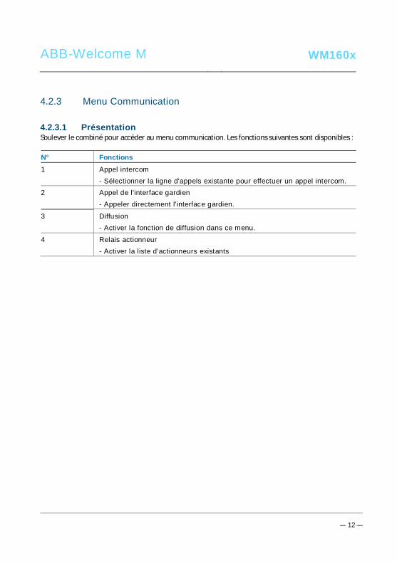
ABB-Welcome M WM160x
— 12 —
Pos: 33 /Di nA4 - A nleitu ngen Onlin e/Ueb ersc hrift en/3 ./Stum m sc halte n @ 2 0\m od_ 132 326 360 7142 _15 .docx @ 1 119 51 @ 3 @ 1Pos: 66 /B usch-J aeg er (Neus truk tur )/M odul -Strukt ur/O nline -Doku me ntatio n/Steu er mod ule - Onlin e-Dok ume ntati on ( -- > Für alle Dok ume nte <- -)/ +++ ++ ++ +++ ++ S eiten umb ruch + +++ ++ ++ +++ + @ 9\m od_ 126 8898 668 093 _0. docx @ 521 49 @ @ 1
4.2.3 Menu CommunicationPos: 31 /Di nA4 - A nleitu ngen Onlin e/In halt/KNX/Do orEnt ry/83 220 -AP-xxx/ Tue r o effne n - 832 20-AP-x xx @ 20\m od_ 132 326 795 847 9_15 .docx @ 1 121 09 @ @ 1
4.2.3.1 PrésentationSoulever le combiné pour accéder au menu communication. Les fonctions suivantes sont disponibles :
N° Fonctions1 Appel intercom
- Sélectionner la ligne d'appels existante pour effectuer un appel intercom.2 Appel de l'interface gardien
- Appeler directement l'interface gardien.
3 Diffusion- Activer la fonction de diffusion dans ce menu.
4 Relais actionneur- Activer la liste d'actionneurs existants

ABB-Welcome M WM160x
— 13 —
4.2.3.2 Appel intercom
Fig. 4 : Appel intercom
Configurer d'abord les listes d'appels interphone dans le menu « Paramétrage des appels entremoniteurs ».
Après avoir sélectionné une liste, appuyer sur le bouton √ pour effectuer l'appel.
INTERCOM CALL
Intercom 1 (001)
Intercom 2

ABB-Welcome M WM160x
— 14 —
4.2.3.3 Appel de l'interface gardien
Fig. 5 : Appel de l'interface gardien
4.2.3.4 Diffusion
Fig. 6 : Diffusion d'un appel
BROADCAST
Longue pression sur le bouton « √ » pourla diffusion
CALL GUARD UNIT
Call Guard Unit
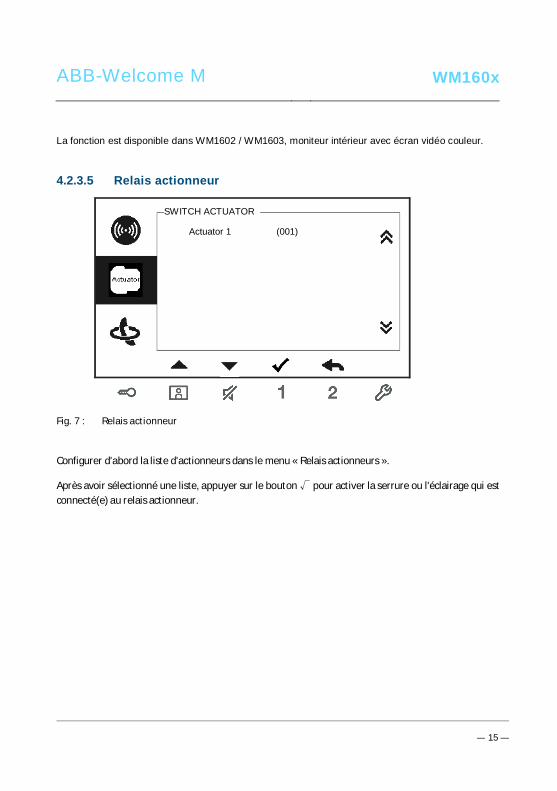
ABB-Welcome M WM160x
— 15 —
La fonction est disponible dans WM1602 / WM1603, moniteur intérieur avec écran vidéo couleur.
4.2.3.5 Relais actionneur
Fig. 7 : Relais actionneur
Configurer d'abord la liste d'actionneurs dans le menu « Relais actionneurs ».
Après avoir sélectionné une liste, appuyer sur le bouton √ pour activer la serrure ou l'éclairage qui estconnecté(e) au relais actionneur.
SWITCH ACTUATOR
Actuator 1 (001)

ABB-Welcome M WM160x
— 16 —
4.3 Paramètres4.3.1 PrésentationAppuyer sur le bouton pour accéder au menu de configuration du système. Les fonctions suivantessont disponibles :
N° Fonctions1 Réglages de l'intercom
- Configurer les listes d'intercom parmi les différents appartements ou ausein d’un même logement
2 Relais actionneur- Configurer la liste des actionneurs dans ce menu
3 Boutons programmables- Configurer les fonctions pour les boutons programmables
4 Transfert d'appels- Configurer la destination (ex. : autres moniteurs intérieurs ou interfaces
gardien) vers laquelle vous voulez transférer les appels pendant votreabsence.
5 Déverrouillage auto- Configurer la plage horaire de déverrouillage automatique
6 Configurer le mot de passe de la platine de rue- Configurer un mot de passe d'ouverture de porte personnalisé, qui est
disponible avec un module clavier situé sur une platine de rue.
7 Sonnerie- Configurer la sonnerie pour les sonnettes extérieures, les sonnettes
intérieures ou autres
8 Volume- Configurer les volumes de sonnerie
9 Date et heure- Configurer les différentes heures.
10 Autres réglages- Autres réglages, ex. : plein écran auto, prise de cliché en automatique…
11 Liste noire- Configurer une liste noire qui est utilisée pour empêcher les appels
indésirables d'autres appartements

ABB-Welcome M WM160x
— 17 —
12 Historique- Consulter toutes les entrées de communication dans le menu, ex. : appels
reçus, appels en absence.
13 Langue- Configurer la langue locale
14 Informations
15 Restauration des réglages d'usine par défautPos: 27 /Di nA4 - A nleitu ngen Onlin e/Ueb ersc hrift en/3 ./Spr ech- und Videov erbi ndu ng @ 20\ mod _13 232 6236 870 0_1 5.do cx @ 1119 27 @ 3 @ 1
4.3.2 Réglages des appels intercom
Fig. 8 : Menu des réglages d'intercom
N° Fonctions1 Choisir la sélection précédente ou parcourir la page vers le haut
2 Choisir la sélection suivante ou parcourir la page vers le bas
1 2 3
6
4
5
Intercom 1 (001)
Intercom 2
Add New
7

ABB-Welcome M WM160x
— 18 —
3 Confirmer la sélection effectuée ou accéder au menu pour la modifier4 Retourner à l'écran précédent
5 Ajouter une nouvelle intercom. 32 intercoms max. peuvent être ajoutées autotal.
6 Liste d'intercom existante : Appuyer sur le bouton √ pour modifier lesréglages.
indique un appel intercom externe vers un autre logement*Pour effectuer un appel intercom externe, chaque appartement doit avoir un
moniteur intérieur principal.
7 Liste d'intercoms existante : Appuyer sur le bouton √ pour modifier lesréglages.
désigne un appel interphone interne dans le même appartement.
Ajouter une nouvelle intercom
Fig. 9 : Ajout d'un nouvel intercom
1Call Type External Intercom
Target Address
Rename 3
INTERCOM
001
mike
Save Cancel
2

ABB-Welcome M WM160x
— 19 —
N° Fonctions1 Pour sélectionner le type d'appel :
- un appel intercom externe désigne un appel vers un autre logement- un appel intercom interne désigne un appel dans un même logement
2 Pour modifier l'adresse de destination, entre 001 et 250.*Si le type d'appel est l'intercom interne, il n'est pas nécessaire de
configurer l'adresse de destination.
3 Renommer l’intercom :Faire défiler les lettres de l'alphabet ou les chiffres un par un avec le
bouton « + » ou « - »
Après le réglage, appuyer sur « Sauvg » pour valider.

ABB-Welcome M WM160x
— 20 —
4.3.3 Réglages du relais actionneur
Fig. 10 : Réglages du relais actionneur
3
4
SWITCH ACTUATOR
Actuator 1 (001)
Add New
Target Address
Rename
002
light
Save Cancel
SWITCH ACTUATOR
2
1
Ajouter un nouveau produit
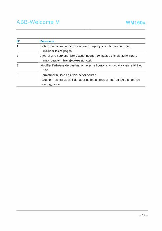
ABB-Welcome M WM160x
— 21 —
N° Fonctions1 Liste de relais actionneurs existante : Appuyer sur le bouton √ pour
modifier les réglages.
2 Ajouter une nouvelle liste d'actionneurs : 10 listes de relais actionneursmax. peuvent être ajoutées au total.
3 Modifier l'adresse de destination avec le bouton « + » ou « - » entre 001 et199.
3 Renommer la liste de relais actionneurs :Parcourir les lettres de l'alphabet ou les chiffres un par un avec le bouton « + » ou « - »

ABB-Welcome M WM160x
— 22 —
4.3.4 Réglages des touches programmables
Fig. 11 : Réglages du bouton reset
N° Fonctions1 Configurer les fonctions des touches programmables, ex. : déverrouillage
d'une 2e serrure, appel de l'interface gardien, activation du relaisactionneur.
*La 2e serrure désigne la serrure qui est connectée au contact sec de laplatine de rue (NC-NO-COM)
*Seules la liste d'appels intercom existante et la liste de relais actionneurspeuvent être assignées à la touche programmable.
Button 1 Release 2nd-Lock
PROGRAM BUTTON
Button 2 None
1

ABB-Welcome M WM160x
— 23 —
4.3.5 Réglages du transfert d'appels
Fig. 12 : Réglages du transfert d'appels
N° Fonctions1 Activer/désactiver la fonction de transfert d'appels.
2 Sélectionner un type d'appel, notamment le moniteur intérieur ou l'interfacegardien.
3 Modifier l'adresse de destination si le type d'appel est un moniteurintérieur.
*Si la fonction de transfert d'appels est activée, la fonction de déverrouillage auto est désactivée.
*La fonction peut uniquement être configurée dans le moniteur intérieur maitre
*La fonction est disponible dans WM1602 / WM1603, moniteur intérieur avec écran vidéo couleur.
1
2
Call Forward
Call Type
√
Indoor
Save Cancel
CALL FORWARD
Target Address 001 3

ABB-Welcome M WM160x
— 24 —
4.3.6 Réglages du déverrouillage auto
Fig. 13 : Réglages du déverrouillage auto
N° Fonctions1 Activer/désactiver la fonction de déverrouillage auto.
2 Activer/désactiver le déverrouillage auto pendant l'heure 1.
3 Configurer l'heure de début et l'heure de fin pour l'heure 1.
4 Activer/désactiver le déverrouillage auto pendant l'heure 2.
5 Configurer l'heure de début et l'heure de fin pour l'heure 2.*Si vous activez la fonction de déverrouillage auto sans configurer le temps de fonctionnement exact,cette fonction est disponible pendant 10 heures.
*Si la fonction de déverrouillage auto est activée, la fonction de transfert d'appels est désactivée.
*La fonction peut uniquement être configurée dans le moniteur intérieur principal.
1Auto Unlock
Time 1
2
AUTO UNLOCK
√
√
08 00
17 00
:
:
Time 2 X
00 00
00 00
:
:
4
35
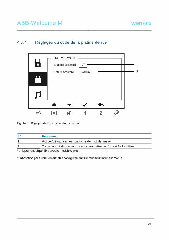
ABB-Welcome M WM160x
— 25 —
4.3.7 Réglages du code de la platine de rue
Fig. 14 : Réglages du code de la platine de rue
N° Fonctions1 Activer/désactiver les fonctions de mot de passe
2 Taper le mot de passe que vous souhaitez au format 6~8 chiffres.*uniquement disponible avec le module clavier.
*La fonction peut uniquement être configurée dans le moniteur intérieur maitre.
1Enable Password
Enter Password
(6-8 digits)
SET OS PASSWORD
√
123456 2

ABB-Welcome M WM160x
— 26 —
4.3.8 Réglages de la sonnerie
Fig. 15 : Sonnerie
N° Fonctions1 Sélectionner la sonnerie pour la platine de rue par défaut.
2 Sélectionner la sonnerie pour les autres platines de rue.
3 Sélectionner la sonnerie pour la porte d'appartement.
4 Sélectionner la sonnerie pour les autres, ex. : appel de l'interface gardienou appel intercom d'autres appartements.
1Default Outdoor
Other Outdoors
RING TONE
Ring Tone 1
Ring Tone 2 2
Doorbell Ring Tone 3
Others Ring Tone 4
3
4
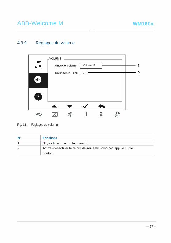
ABB-Welcome M WM160x
— 27 —
4.3.9 Réglages du volume
Fig. 16 : Réglages du volume
N° Fonctions1 Régler le volume de la sonnerie.
2 Activer/désactiver le retour de son émis lorsqu'on appuie sur lebouton.
1Ringtone Volume
Touchbutton Tone
VOLUME
Volume 3
2√
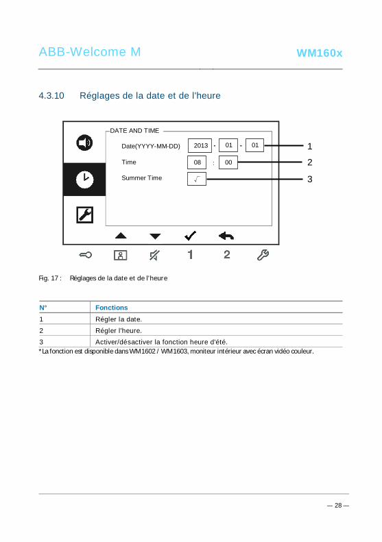
ABB-Welcome M WM160x
— 28 —
4.3.10 Réglages de la date et de l'heure
Fig. 17 : Réglages de la date et de l'heure
N° Fonctions1 Régler la date.
2 Régler l'heure.
3 Activer/désactiver la fonction heure d'été.*La fonction est disponible dans WM1602 / WM1603, moniteur intérieur avec écran vidéo couleur.
1Date(YYYY-MM-DD)
Time
DATE AND TIME
2013
208
Summer Time √
: 00
- 01 - 01
3

ABB-Welcome M WM160x
— 29 —
4.3.11 Réglages des options
Fig. 18 : Réglages des options
N° Fonctions1 Activer/désactiver la fonction plein écran auto.
2 Activer/désactiver la fonction prise automatique de photos.*La fonction est disponible dans WM1602 / WM1603, moniteur intérieur
avec écran vidéo couleur.3 Activer/désactiver la fonction de contrôle de statut de porte (uniquement
disponible si le capteur est installé avec une platine de rue ; clignotelorsque la porte est ouverte).
4 Activer/désactiver la fonction appel en absence ( clignote lorsqu'il y a unappel en absence).
*La fonction est disponible dans WM1602 / WM1603, moniteur intérieuravec écran vidéo couleur.
1Auto Full Screen
Auto-snapshots
DOOR ENTRY SYSTEM
2
Door Status Check
√
3
Missed
√
√
√ 4

ABB-Welcome M WM160x
— 30 —
4.3.12 Réglages de la liste noire
Fig. 19 : Réglages de la liste noire
Blacklist 1
Add New
BLACKLIST
(001)
Target Address
BLACKLIST
Save Cancel
002
1
2
3

ABB-Welcome M WM160x
— 31 —
N° Fonctions1 La liste noire existante. Appuyer sur le bouton √ pour modifier le réglage.
2 Ajouter une nouvelle adresse à la liste noire. 32 éléments dans la listenoires max. peuvent être ajoutées au total.
3 Modifier l'adresse de destination avec le bouton « + » ou « - » entre 001 et250.
*La fonction peut uniquement être configurée dans le moniteur intérieur principal.
*La fonction est disponible dans WM1602 / WM1603, moniteur intérieur avec écran vidéo couleur.

ABB-Welcome M WM160x
— 32 —
4.3.13 Consultation de l'historique
Fig. 20 : Consultation de l'historique
N° Fonctions1 100 évènements maximum peuvent être enregistrés dans le menu
« historique ».-Si la fonction prise de photos est activée, une icône est affichée. Si
●
HISTORY
1/2
Outdoor -1
1/632013-03-21
16:45
Outdoor - 1
● 2013-03-21 Outdoor - 1
● 2013-03-21 Outdoor - 1
1
2
3

ABB-Welcome M WM160x
— 33 —
aucune fonction prise de photos n'est activée, l'icône n'est pas affichée.- La date, l'heure et le type d'évènement sont enregistrés avec la photo.- Directions : désigne les appels sortant désigne les appels reçus désigne les appels en absence
2 Appuyer sur ce bouton pour consulter les détails de cet évènement.Deux photos sont toujours prises lorsqu'un visiteur sonne à la porte.
3 Appuyer sur ce bouton pour supprimer un enregistrement.*La fonction est disponible dans WM1602 / WM1603, moniteur intérieur avec écran vidéo couleur.
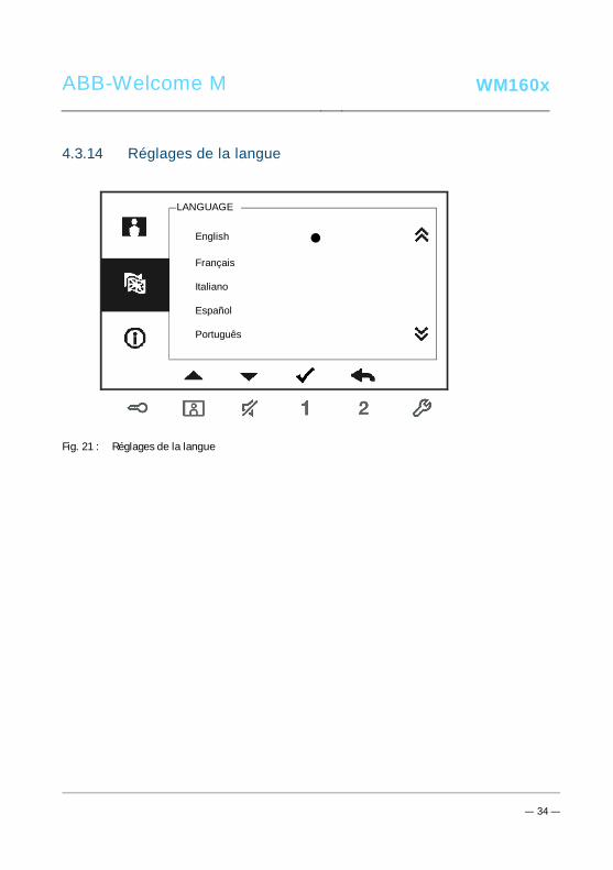
ABB-Welcome M WM160x
— 34 —
4.3.14 Réglages de la langue
Fig. 21 : Réglages de la langue
English
LANGUAGE
Français
Italiano
Português
Español

ABB-Welcome M WM160x
— 35 —
4.3.15 Informations
Fig. 22 : Informations du moniteur intérieur (numérisation du code QR pour obtenir desinstructions détaillées du moniteur intérieur)
Flash Version: V0.11_130723
INFORMATION
MCU Version: V0.11_130722
M/S: Master
Default Outdoor: 1
Indoor St. Add.: 001

ABB-Welcome M WM160x
— 36 —
4.3.16 Restauration des réglages d'usine par défaut
Fig. 23 : Restauration des réglages d'usine par défaut
N° Fonctions1 Réinitialisation :
Réinitialiser l'appareil et restaurer toutes les configurations par défaut.L'opération ne supprime pas les données programmées et l'historique,comme les listes d'interphones et les listes de relais actionneurs.
2 Effacer toutes données :Supprimer toutes les données programmées et l'historique. Tous les
réglages d'usine par défaut de toutes les configurations sont égalementrestaurés.
RESET FACTORY DEFAULT
Are you sure to reset?
Cancel OK
Reset All Settings
Clear All Data ×
√

ABB-Welcome M WM160x
— 37 —
Pos: 67 /Di nA4 - A nleitu ngen Onlin e/Ueb ersc hrift en/2 ./Reini gung @ 1 9\m od_ 131 0733 980 533 _15. docx @ 10 785 3 @ 2 @ 1
4.4 NettoyagePos: 68 /Di nA4 - A nleitu ngen Onlin e/In halt/KNX/Do orEnt ry/Reini gun g/Reini gun g Touchsc ree nm onito r @ 19\m od_ 131 073 410 897 8_15 .docx @ 1 078 62 @ @ 1
Attention
Risque d'endommagement de la surface de l'écran.
La surface de l'écran peut être endommagée par des objets durs outranchants !Ne jamais utiliser d'objets pour effectuer des saisies sur l'écran tactile.– Utiliser son doigt ou un stylet en plastique.
La surface de l'écran peut être endommagée par des fluides de nettoyage ouagents abrasifs !– Nettoyer les surfaces à l'aide d'un chiffon doux et d'un produit pour
vitres vendu dans le commerce.– Ne jamais utiliser d'agents de nettoyage abrasifs.
Pos: 69 /B usch-J aeg er (Neus truk tur )/M odul -Strukt ur/O nline -Doku me ntatio n/Steu er mod ule - Onlin e-Dok ume ntati on ( -- > Für alle Dok ume nte <- -)/ +++ ++ ++ +++ ++ S eiten umb ruch + +++ ++ ++ +++ + @ 9\m od_ 126 8898 668 093 _0. docx @ 521 49 @ @ 1

ABB-Welcome M WM160x
— 38 —
Pos: 70 /Di nA4 - A nleitu ngen Onlin e/Ueb ersc hrift en/2 ./Ge raet eeins tellun gen @ 1 8\mo d_1 302 768 847 744 _15. docx @ 10 354 8 @ 2 @ 1
4.5 Réglage de l'appareilPos: 71 /Di nA4 - A nleitu ngen Onlin e/Ueb ersc hrift en/3 ./Abschl usswide rsta nd @ 19\ mod _13 219 5807 990 6_1 5.do cx @ 1100 83 @ 3 @ 1
Pos: 72 /Di nA4 - A nleitu ngen Onlin e/In halt/KNX/Do orEnt ry/Bedie nun g/Abschl usswide rsta nd s etzen 83 220 -AP-xxx @ 19\ mod _13 1072 339 236 9_1 5.do cx @ 1 078 41 @ @ 1
Fig. 24 :Pos: 74 /Di nA4 - A nleitu ngen Onlin e/In halt/KNX/Do orEnt ry/Bedie nun g/M aste r/Slave Sc halte r setz en 832 20-AP-xxx @ 1 9\m od_1 310 723 320 966 _15. docx @ 10 783 3 @ @
1. Station
Cavalier pour configurer l'adresse de la platine de rue par défaut.
2. X100 X10 X1Cavalier pour configurer l'adresse du moniteur intérieur.
EXEMPLE : configuration de l'adresse 024.
3. Fonction Master / SlaveUn seul moniteur intérieur dans chaque appartement doit être configuré comme
« Master » (le cavalier doit être configuré comme « M/S on »). Tous les moniteursintérieurs supplémentaires dans le même appartement doivent être configurés comme« Slave » (Le cavalier doit être configuré comme « M/S off »).
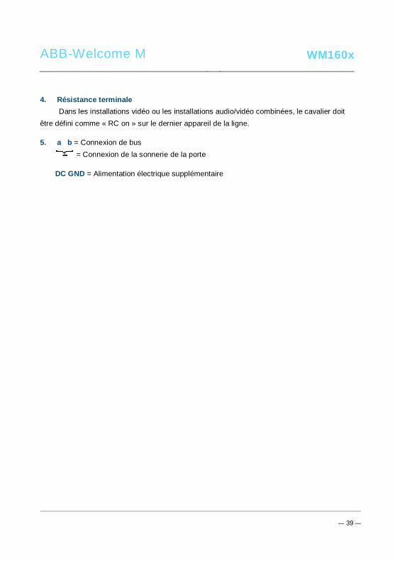
ABB-Welcome M WM160x
— 39 —
4. Résistance terminaleDans les installations vidéo ou les installations audio/vidéo combinées, le cavalier doit
être défini comme « RC on » sur le dernier appareil de la ligne.
5. a b = Connexion de bus= Connexion de la sonnerie de la porte
DC GND = Alimentation électrique supplémentairePos: 75 /B usch-J aeg er (Neus truk tur )/M odul -Strukt ur/O nline -Doku me ntatio n/Steu er mod ule - Onlin e-Dok ume ntati on ( -- > Für alle Dok ume nte <- -)/ +++ ++ ++ +++ ++ S eiten umb ruch + +++ ++ ++ +++ + @ 9\m od_ 126 8898 668 093 _0. docx @ 521 49 @ @ 1
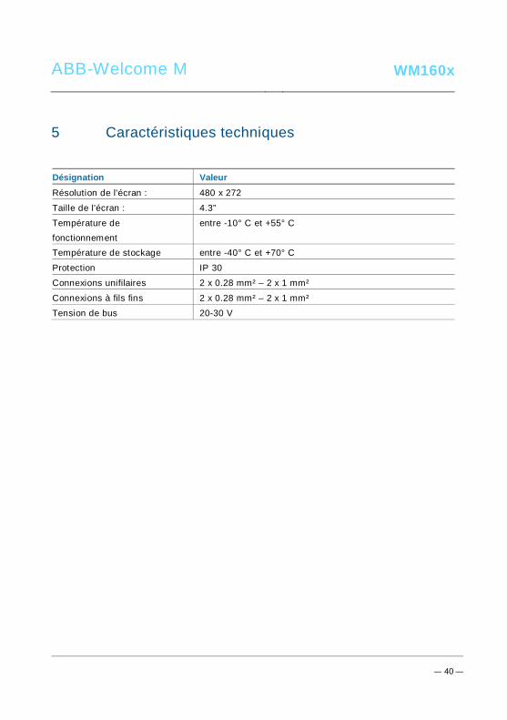
ABB-Welcome M WM160x
— 40 —
Pos: 76 /Di nA4 - A nleitu ngen Onlin e/Ueb ersc hrift en/1 ./Technisc he D aten @ 18 \mo d_1 302 615 863 001 _15. docx @ 10 341 6 @ 1 @ 1
5 Caractéristiques techniquesPos: 77 /Di nA4 - A nleitu ngen Onlin e/In halt/KNX/Do orEnt ry/83 220 -AP-xxx/ Tech nische Date n - 832 20-AP-x xx @ 1 8\m od_ 130 321 285 4559 _15 .docx @ 1 037 05 @ @ 1
Désignation ValeurRésolution de l'écran : 480 x 272
Taille de l'écran : 4.3”
Température defonctionnement
entre -10° C et +55° C
Température de stockage entre -40° C et +70° C
Protection IP 30
Connexions unifilaires 2 x 0.28 mm² – 2 x 1 mm²
Connexions à fils fins 2 x 0.28 mm² – 2 x 1 mm²
Tension de bus 20-30 V
Pos: 78 /B usch-J aeg er (Neus truk tur )/M odul -Strukt ur/O nline -Doku me ntatio n/Steu er mod ule - Onlin e-Dok ume ntati on ( -- > Für alle Dok ume nte <- -)/ +++ ++ ++ +++ ++ S eiten umb ruch + +++ ++ ++ +++ + @ 9\m od_ 126 8898 668 093 _0. docx @ 521 49 @ @ 1

ABB-Welcome M WM160x
— 41 —
Pos: 79 /B usch-J aeg er (Neus truk tur )/M odul -Strukt ur/O nline -Doku me ntatio n/Übe rsch rifte n ( --> Fü r alle Doku men te < -- )/1. E bene /M - O/ Mont age / Ins tallatio n @ 18\ mod _13 0261 396 611 1_1 5.do cx @ 1 033 73 @ 1 @ 1
6 Montage / InstallationPos: 80 /B usch-J aeg er (Neus truk tur )/M odul -Strukt ur/O nline -Doku me ntatio n/Siche rheit (- -> Fü r alle D oku ment e < --) /War nhinweis e/Siche rheit - Nie ders pan nun gs- und 230 V-Leit ung en @ 18\ mod _13 026 178 214 91_1 5.d ocx @ 103 465 @ @ 1
Avertissement
Tension électrique !
Danger de mort et d'incendie en raison de la présence d'une tensionélectrique de 100-240 V.– Les câbles basse tension et 100-240 V ne doivent pas être installés
ensemble dans une prise encastrée !En cas de court-circuit, il existe un risque de charge 100-240 V sur laligne basse tension.
Pos: 81 /B usch-J aeg er (Neus truk tur )/M odul -Strukt ur/O nline -Doku me ntatio n/Siche rheit (- -> Fü r alle D oku ment e < --) /War nhinweis e/Siche rheit - Fachk enn tnisse @ 18 \mo d_1 302 774 384 017_ 15. docx @ 10 356 4 @ 2 @ 1
ABB-Welcome M WM160x
— 42 —
6.1 Exigences à l'égard de l'électricien
Avertissement
Tension électrique !
L'installation de l'appareil par un électricien est uniquement possible s'ilpossède les connaissances techniques et compétences nécessaires.• Toute installation incorrecte peut mettre en danger votre vie et celle de
l'utilisateur du système électrique.• Toute installation incorrecte peut entraîner des dommages, p. ex. : en
raison d'un incendie.Les connaissances nécessaires minimum et les exigences relatives à
l'installation sont les suivantes :• Appliquer les « cinq règles de sécurité » (DIN VDE 0105, EN 50110) :
1. Débrancher l'appareil de la source d'alimentation ;2. Empêcher tout rebranchement de l'appareil ;3. S'assurer de l'absence de tension ;4. Raccorder à la terre ;5. Recouvrir ou isoler les pièces voisines sous tension.
• Porter des vêtements de protection appropriés.• Utiliser uniquement des outils et appareils de mesure appropriés.• Vérifier le type de réseau d'alimentation (système TN, système IT,
système TT) pour garantir les conditions d'alimentation électriquessuivantes (connexion à la terre classique, mise à la terre de protection,mesures supplémentaires nécessaires, etc.).
Pos: 82 /Di nA4 - A nleitu ngen Onlin e/In halt/KNX/Do orEnt ry/M onta ge/ Mont age hinweis e - Allg emei n @ 1 9\m od_ 131 056 367 047 8_15 .docx @ 1 077 43 @ 2 @ 1

ABB-Welcome M WM160x
— 43 —
6.2 Consignes d'installation générales• Terminer toutes les extrémités du système de câblage via un appareil de bus connecté
(p. ex., moniteur intérieur, platine de rue, appareil système).• Ne pas installer le contrôleur système juste à côté du transformateur de sonnerie et
autres alimentations électriques (pour éviter les interférences).• Ne pas installer les câbles du bus système avec des câbles 100-240 V.• Ne pas utiliser des câbles communs pour les câbles de raccordement des portiers et les
câbles du bus système.• Éviter les ponts entre les différents types de câbles.• Utiliser uniquement deux câbles pour le bus système dans un câble à quatre conducteurs
ou plus.• En cas de structure en boucle, ne jamais installer les bus de départ et d'arrivée à
l'intérieur du même câble.• Ne jamais installer les bus interne et externe à l'intérieur du même câble.Pos: 83 /B usch-J aeg er (Neus truk tur )/M odul -Strukt ur/O nline -Doku me ntatio n/Steu er mod ule - Onlin e-Dok ume ntati on ( -- > Für alle Dok ume nte <- -)/ +++ ++ ++ +++ ++ S eiten umb ruch + +++ ++ ++ +++ + @ 9\m od_ 126 8898 668 093 _0. docx @ 521 49 @ @ 1
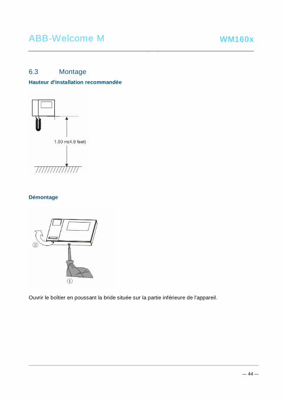
ABB-Welcome M WM160x
— 44 —
Pos: 84 /B usch-J aeg er (Neus truk tur )/M odul -Strukt ur/O nline -Doku me ntatio n/Übe rsch rifte n ( --> Fü r alle Doku men te < -- )/2. E bene /M - O/ Mont age @ 1 8\m od_1 302 615 960 458 _15. docx @ 10 342 4 @ 2 @ 1
6.3 MontagePos: 85. 1 /DinA4 - Anleit ung en O nline/I nhal t/KNX/DoorE ntry/ 832 20-AP-xxx /Mo nta ge - Mo dule/ Mon tag e - Mon tage dos e -- 83 220 -AP-xxx @ 19\ mod _132 325 040 684 8_1 5.doc x @ 1 110 98 @ @ 1
Hauteur d'installation recommandée
Démontage
Ouvrir le boîtier en poussant la bride située sur la partie inférieure de l'appareil.

ABB-Welcome M WM160x
— 45 —
Dimensions d'installation
1. La partie inférieure de l'appareil comporte des trous de vis pour le montage mural d'aprèsles dimensions indiquées ci-dessus.
2. De plus, la partie inférieure de l'appareil peut être fixée sur la boite d’encastrementexistante. Les dimensions des boites compatibles sont indiquées dans les figures ci-dessus.

ABB-Welcome M WM160x
— 46 —
Câblage
Fixer la partie inférieure de l'appareil et effectuer le câblage en se référant aux figures. Lasection isolée de l'extrémité de câble ne doit pas mesurer plus de 10 mm.
Réglages
Définir les adresses des platines de rue préférées et l'adresse du moniteur intérieur sur lecavalier (voir Chapitre « Réglage de l'appareil »).
Montage mural
1. Fixer la partie inférieure de l'appareil sur le mur.

ABB-Welcome M WM160x
— 47 —
2. Accrocher la partie supérieure de l'appareil sur sa partie inférieure, placer le dessus del'appareil sur les pattes d'encliquetage, puis enfoncer le dessous sur la partie inférieurede l'appareil jusqu'à ce qu'il soit coincé par la bride.
Montage avec boite d’encastrement
1. Fixer la partie inférieure de l'appareil sur le boîtier encastré existant.
2. Accrocher la partie supérieure de l'appareil sur sa partie inférieure, placer le dessus del'appareil sur les pattes d'encliquetage, puis enfoncer le dessous sur la partie inférieurede l'appareil jusqu'à ce qu'il soit coincé par la bride.

ABB-Welcome M WM160x
— 48 —
Montage avec support de bureau
1. Fixer la partie inférieure de l'appareil sur le support de bureau.
2. Accrocher la partie supérieure de l'appareil sur sa partie inférieure, placer le dessus del'appareil sur les pattes d'encliquetage, puis enfoncer le dessous sur la partie inférieurede l'appareil jusqu'à ce qu'il soit coincé par la bride.
L'installation du moniteur intérieur est maintenant terminée.
Pos: 94 /B usch-J aeg er (Neus truk tur )/M odul -Strukt ur/O nline -Doku me ntatio n/Steu er mod ule - Onlin e-Dok ume ntati on ( -- > Für alle Dok ume nte <- -)/ +++ ++ ++ +++ ++ S eiten umb ruch + +++ ++ ++ +++ + @ 9\m od_ 126 8898 668 093 _0. docx @ 521 49 @ @ 1

ABB-Welcome M WM160x
Pos: 95 /Di nA4 - A nleitu ngen Onlin e/In halt/KNX/Do orEnt ry/Proj ektier ung -M erkbl att/Pr ojektie rPos: 9 7 /Busc h-Ja ege r (N eust ruktu r)/ Mo dul-Str uktu r/Onli ne-D oku ment ation /Rückseit en (-- > Für alle Dok um ente <- -)/R ückseit e - Bus ch-J aeg er - Allgem ein @ 20\ mod _13 273 200 748 86_1 5.d ocx @ 137 103 @ @ 1
Mentions légales=== E nde der Liste für Tex tma rke Ba ckcove r = ==
Nous nous réservons le droit d'effectuer à tout moment des modifications techniques ou demodifier le contenu de ce document sans préavis.Les spécifications détaillées convenues au moment de la commande s'appliquent à toutes lescommandes. ABB ne peut être tenu responsable des erreurs ou omissions dans ce document. Nous nous réservons tous les droits de propriété sur ce document, ainsi que sur lesinformations et les illustrations qu'il contient. Le document et son contenu, ou extraits de celui-ci, ne doivent pas être reproduits, transmis ou réutilisés par des tiers sans avis écrit préalabled'ABB.

Sistemi di videocitofonia│ Welcome M │ Manuale utente
ABB Welcome M
Pos: 2 /DinA4 - Anl eitun gen Online /Inh alt/KNX/Doo rEntry /832 20-AP- xxx/Tit elblat t - 832 20-AP-xxx - ABB @ 1 9\m od_ 132 3249 806 476 _15. docx @ 11 108 4 @ @ 1
M22301-.
M22302-.
M22303-.
Posto Interno Monitorcon cornetta a colori
=== E nde der Liste für Tex tma rke C over == =

ABB-Welcome
| — 2 —
Pos: 4 /Busc h-Ja ege r (N eust rukt ur)/ Mo dul-St ruktu r/Onli ne-D oku ment ation /Inh altsve rzeich nis ( --> Fü r alle Doku men te <-- )/In haltsve rzeic hnis @ 19\ mod _13 206 490 4438 6_1 5.d ocx @ 109 653 @ @ 1
1 Sicurezza .................................................................................................. 32 Uso previsto .............................................................................................. 33 Ambiente .................................................................................................. 4
3.1 Dispositivi ABB.......................................................................... 44 Funzionamento ......................................................................................... 5
4.1 Funzionamento standard ........................................................... 54.1.1 Comandi ................................................................................... 54.2 Azioni di controllo ...................................................................... 84.2.1 Chiamata in entrata/durante la conversazione ............................ 84.2.2 Impostazione display e volume durante la chiamata ................. 104.2.3 Menu comunicazione .............................................................. 114.3 Impostazioni............................................................................ 154.3.1 Menù comunicazione .............................................................. 154.3.2 Impostazione chiamata intercomunicante ................................. 164.3.3 Impostazione attuatore ............................................................ 194.3.4 Impostazione pulsante programmabile ..................................... 204.3.5 Impostazione inoltro chiamata ................................................. 224.3.6 Impostazione sblocco automatico ............................................ 234.3.7 Impostazione password posto esterno ..................................... 244.3.8 Impostazione suoneria ............................................................ 254.3.9 Impostazione volume .............................................................. 264.3.10 Impostazione data e ora .......................................................... 274.3.11 Impostazione sistema di videocitofonia .................................... 284.3.12 Impostazione blacklist ............................................................. 294.3.13 Revisione archivio ................................................................... 314.3.14 Impostazione della lingua ........................................................ 334.3.15 Info ......................................................................................... 334.3.16 Ripristino delle impostazioni di default ...................................... 344.4 Pulizia ..................................................................................... 354.5 Regolazione del dispositivo ..................................................... 36

ABB-Welcome
| — 3 —
5 Dati tecnici .............................................................................................. 386 Montaggio/Installazione ........................................................................... 39
6.1 Obblighi dell'elettricista ............................................................ 406.2 Istruzioni generali di installazione ............................................. 416.3 Montaggio ............................................................................... 42
=== E nde der Liste für Tex tma rke TOC == =Pos: 6 /Busc h-Ja ege r (N eust rukt ur)/ Mo dul-St ruktu r/Onli ne-D oku ment ation /Übe rschri ften (- -> Für alle D okum ent e < --)/ 1. Eb ene/S - T /Sicher heit @ 18\ mod _13 026 127 917 90_ 15.d ocx @ 103 357 @ 1 @ 1
1 SicurezzaPos: 7 /Busc h-Ja ege r (N eust rukt ur)/ Mo dul-St ruktu r/Onli ne-D oku ment ation /Sicher heit (-- > Für alle Dok um ente <- -)/Wa rn hinweise /Sicher heit - 23 0 V @ 18\m od_ 130 260 681 675 0_15 .docx @ 1 033 08 @ @ 1
Attenzione
Tensione elettrica!
Rischio di morte ed incendio dovuto alla presenza di tensione elettrica100-240 V.– Gli interventi sul sistema di alimentazione 100-240V possono essere
effettuati solo da elettricisti autorizzati.– Scollegare l'alimentazione di rete prima dell'installazione e/o
dello smontaggio.
Pos: 8 /Busc h-Ja ege r (N eust rukt ur)/ Mo dul-St ruktu r/Onli ne-D oku ment ation /Übe rschri ften (- -> Für alle D okum ent e < --)/ 1. Eb ene/A - F /Bestim mun gsge mä ßer Geb rau ch @ 18\ mod _13 027 6332 131 6_1 5.do cx @ 1034 83 @ 1 @ 1
2 Uso previstoPos: 9 /DinA4 - Anl eitun gen Online /Inh alt/KNX/Doo rEntry /832 20-AP- xxx/Besti mmu ngsg em aesse r Ge bra uch - 83 220 -AP-xxx- 500 @ 2 0\mo d_1 324 561 168 699 _15. docx @ 11 272 8 @ @ 1
Il dispositivo M2230x-x è parte integrante del sistema di videocitofonia Welcome M diABB e funziona unicamente con i componenti di questo sistema. Il dispositivo deveessere installato in ambienti chiusi e asciutti.
Pos: 10 /B usch-J aeg er (Neus truk tur )/M odul -Strukt ur/O nline -Doku me ntatio n/Übe rsch rifte n ( --> Fü r alle Doku men te < -- )/1. E bene /U - Z/U mwelt @ 18\ mod _13 026 141 5896 7_1 5.d ocx @ 103 383 @ 1 @ 1
ABB-Welcome
3 AmbientePos: 11 /B usch-J aeg er (Neus truk tur )/M odul -Strukt ur/O nline -Doku me ntatio n/Umw elt ( --> Für all e Doku me nte <-- )/Hinweis e/Hinw eis - U mwelt - Hinweis Elektr oge räte @ 1 8\mo d_1 302 763 973 434 _15. docx @ 10 350 0 @ @ 1
Prestare attenzione alla tutela dell'ambiente!
I dispositivi elettrici ed elettronici usati devono essere smaltitiseparatamente dai rifiuti domestici.– Il dispositivo è composto da materie prime che possono
essere riciclate. Occorre pertanto smaltire il dispositivo pressospecifici centri di raccolta.
Pos: 12 /Di nA4 - A nleitu ngen Onlin e/Ueb ersc hrift en/2 ./ABB Gera ete @ 19 \mo d_1 323 162 843 832_ 15. docx @ 11 087 5 @ 2 @ 1
3.1 Dispositivi ABBPos: 13 /B usch-J aeg er (Neus truk tur )/M odul -Strukt ur/O nline -Doku me ntatio n/Umw elt ( --> Für all e Doku me nte <-- )/Hinweis e/Hinw eis - U mwelt - ABB Elektro ger äte @ 19\ mo d_1 3231 627 458 39_ 15.d ocx @ 110 867 @ @ 1
Tutti gli imballaggi e i dispositivi ABB riportano i marchi e i sigilli di verifica per il correttosmaltimento. Smaltire gli imballaggi, i dispositivi elettrici e i relativi componenti pressocentri di raccolta autorizzati e società addette allo smaltimento rifiuti.I prodotti ABB soddisfano i requisiti di legge, in particolare delle leggi relative aidispositivi elettrici ed elettronici, e il regolamento per la registrazione, la valutazione,l'autorizzazione e la restrizione delle sostanze chimiche (REACH).(Direttiva UE 2002/96/CE RAEE e 2002/95/CE RoHS)(Regolamento 1907/2006/CE (REACH) e legge per l'implementazione del regolamentoCE)
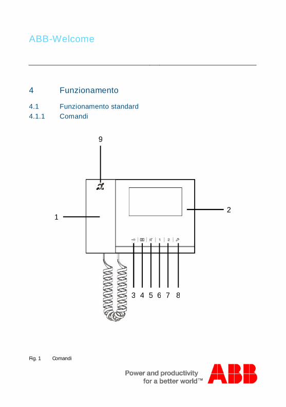
ABB-Welcome
Pos: 18 /Di nA4 - A nleitu ngen Onlin e/Ueb ersc hrift en/1 ./Bedie nun g @ 18\m od_ 130 261 392 416 5_15 .docx @ 1 033 65 @ 1 @ 1
4 FunzionamentoPos: 19 /Di nA4 - A nleitu ngen Onlin e/Ueb ersc hrift en/2 ./Nor male r Bet rieb @ 18 \mo d_1 302 768 8209 65_ 15. docx @ 10 3540 @ 2 @ 1
4.1 Funzionamento standardPos: 20 /Di nA4 - A nleitu ngen Onlin e/Ueb ersc hrift en/3 ./Bedie nele men te @ 20\ mod _13 232 6022 055 9_1 5.do cx @ 1 116 47 @ 3 @ 1
4.1.1 ComandiPos: 21 /Di nA4 - A nleitu ngen Onlin e/In halt/KNX/Do orEnt ry/83 220 -AP-xxx/Be dienel eme nte - 8 322 0-AP-xxx @ 18\ mo d_1 3032 128 536 05_ 15.d ocx @ 103 673 @ @ 1
Fig. 1 Comandi
12
3
9
4 5 6 7 8
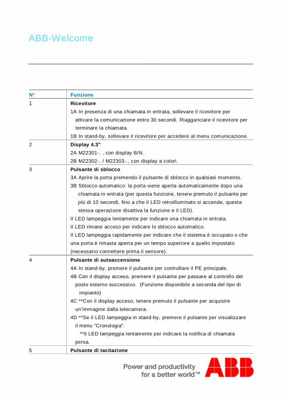
ABB-Welcome
N° Funzione1 Ricevitore
1A In presenza di una chiamata in entrata, sollevare il ricevitore perattivare la comunicazione entro 30 secondi. Riagganciare il ricevitore perterminare la chiamata.
1B In stand-by, sollevare il ricevitore per accedere al menu comunicazione.
2 Display 4.3"2A M22301-. , con display B/N.2B M22302-. / M22303-., con display a colori.
3 Pulsante di sblocco3A Aprire la porta premendo il pulsante di sblocco in qualsiasi momento.3B Sblocco automatico: la porta viene aperta automaticamente dopo una
chiamata in entrata (per questa funzione, tenere premuto il pulsante perpiù di 10 secondi, fino a che il LED retroilluminato si accende, questastessa operazione disattiva la funzione e il LED).
Il LED lampeggia lentamente per indicare una chiamata in entrata.Il LED rimane acceso per indicare lo sblocco automatico.Il LED lampeggia rapidamente per indicare che il sistema è occupato o cheuna porta è rimasta aperta per un tempo superiore a quello impostato(necessario connettere prima il sensore).
4 Pulsante di autoaccensione4A In stand-by, premere il pulsante per controllare il PE principale.4B Con il display acceso, premere il pulsante per passare al controllo del
posto esterno successivo. (Funzione disponibile a seconda del tipo diimpianto)
4C **Con il display acceso, tenere premuto il pulsante per acquisireun’immagine dalla telecamera.
4D **Se il LED lampeggia in stand-by, premere il pulsante per visualizzareil menu "Cronologia".
**Il LED lampeggia lentamente per indicare la notifica di chiamatapersa.
5 Pulsante di tacitazione
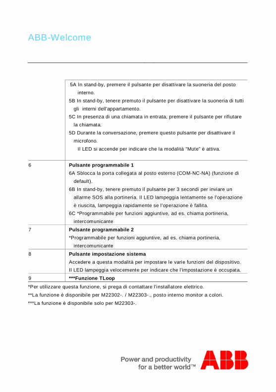
ABB-Welcome
5A In stand-by, premere il pulsante per disattivare la suoneria del postointerno.
5B In stand-by, tenere premuto il pulsante per disattivare la suoneria di tuttigli interni dell'appartamento.
5C In presenza di una chiamata in entrata, premere il pulsante per rifiutarela chiamata.
5D Durante la conversazione, premere questo pulsante per disattivare ilmicrofono.
Il LED si accende per indicare che la modalità “Mute” è attiva.
6 Pulsante programmabile 16A Sblocca la porta collegata al posto esterno (COM-NC-NA) (funzione di
default).6B In stand-by, tenere premuto il pulsante per 3 secondi per inviare un
allarme SOS alla portineria. Il LED lampeggia lentamente se l'operazioneè riuscita, lampeggia rapidamente se l'operazione è fallita.
6C *Programmabile per funzioni aggiuntive, ad es. chiama portineria,intercomunicante
7 Pulsante programmabile 2*Programmabile per funzioni aggiuntive, ad es. chiama portineria,
intercomunicante
8 Pulsante impostazione sistemaAccedere a questa modalità per impostare le varie funzioni del dispositivo.Il LED lampeggia velocemente per indicare che l'impostazione è occupata.
9 ***Funzione TLoop*Per utilizzare questa funzione, si prega di contattare l'installatore elettrico.
**La funzione è disponibile per M22302-. / M22303-., posto interno monitor a colori.
***La funzione è disponibile solo per M22303-.Pos: 22 /B usch-J aeg er (Neus truk tur )/M odul -Strukt ur/O nline -Doku me ntatio n/Steu er mod ule - Onlin e-Dok ume ntati on ( -- > Für alle Dok ume nte <- -)/ +++ ++ ++ +++ ++ S eiten umb ruch + +++ ++ ++ +++ + @ 9\m od_ 126 8898 668 093 _0. docx @ 521 49 @ @ 1

ABB-Welcome
Pos: 26 /Di nA4 - A nleitu ngen Onlin e/Ueb ersc hrift en/2 ./Bedie nakti onen @ 2 0\m od_ 1323 262 294 281 _15. docx @ 11 191 1 @ 2 @ 1
4.2 Azioni di controlloPos: 27 /Di nA4 - A nleitu ngen Onlin e/Ueb ersc hrift en/3 ./Spr ech- und Videov erbi ndu ng @ 20\ mod _13 232 6236 870 0_1 5.do cx @ 1119 27 @ 3 @ 1
4.2.1 Chiamata in entrata/durante la conversazionePos: 28 /Di nA4 - A nleitu ngen Onlin e/In halt/KNX/Do orEnt ry/83 220 -AP-xxx/Sp rech - u nd Vide over bind ung - 8 322 0-AP-xxx @ 20\ mo d_1 3232 623 418 52_ 15.d ocx @ 111 919 @ @ 1
Fig. 2 Chiamata in entrata/durante la conversazione
Durante la chiamata sono disponibili le seguenti funzioni:N° Funzione1 Sollevare il ricevitore per accettare la chiamata in entrata; durante la
conversazione, riagganciare il ricevitore per terminare la chiamata.
2 Premere questo pulsante per aprire la porta da cui proviene la chiamata.
3-A Premere questo pulsante per controllare la videocamera esterna del postoesterno, se presente.
3-B Tenere premuto il pulsante per scattare una foto (snapshot) manuale.*La funzione è disponibile per M22302-. / M22303-., posto interno monitor
a colori.
30s
2 4 6
7
8
3 51
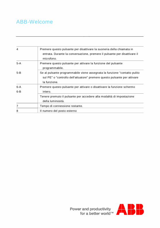
ABB-Welcome
4 Premere questo pulsante per disattivare la suoneria della chiamata inentrata. Durante la conversazione, premere il pulsante per disattivare ilmicrofono.
5-A Premere questo pulsante per attivare la funzione del pulsanteprogrammabile.
5-B Se al pulsante programmabile viene assegnata la funzione "contatto pulitosul PE" o "controllo dell'attuatore" premere questo pulsante per attivarela funzione.
6-A6-B
Premere questo pulsante per attivare o disattivare la funzione schermointero.
Tenere premuto il pulsante per accedere alla modalità di impostazionedella luminosità.
7 Tempo di connessione restante.
8 Il numero del posto esternoPos: 29 /B usch-J aeg er (Neus truk tur )/M odul -Strukt ur/O nline -Doku me ntatio n/Steu er mod ule - Onlin e-Dok ume ntati on ( -- > Für alle Dok ume nte <- -)/ +++ ++ ++ +++ ++ S eiten umb ruch + +++ ++ ++ +++ + @ 9\m od_ 126 8898 668 093 _0. docx @ 521 49 @ @ 1

ABB-Welcome
Pos: 30 /Di nA4 - A nleitu ngen Onlin e/Ueb ersc hrift en/3 ./Tuer oeff nen @ 2 0\mo d_1 323 263 277 453 _15. docx @ 11 193 5 @ 3 @ 1
4.2.2 Impostazione display e volume durante la chiamataPos: 31 /Di nA4 - A nleitu ngen Onlin e/In halt/KNX/Do orEnt ry/83 220 -AP-xxx/ Tue r o effne n - 832 20-AP-x xx @ 20\m od_ 132 326 795 847 9_15 .docx @ 1 121 09 @ @ 1
Fig. 3 Impostazione display e volume durante la chiamata
Tenere premuto il pulsante per 3 secondi per accedere alla modalità di impostazione display evolume durante la chiamata o la conversazione. Sono disponibili le seguenti funzioni:
N° Funzione1 Pulsanti di navigazione (su, giù, invio, cancella, ecc.)
2 Premere i pulsanti per attivare la funzione associata
3 *Saturazione
4 *Luminosità
5 Valore impostato
*La funzione è disponibile per M22302-. / M22303-., posto interno monitor a colori.Pos: 32 /B usch-J aeg er (Neus truk tur )/M odul -Strukt ur/O nline -Doku me ntatio n/Steu er mod ule - Onlin e-Dok ume ntati on ( -- > Für alle Dok ume nte <- -)/ +++ ++ ++ +++ ++ S eiten umb ruch + +++ ++ ++ +++ + @ 9\m od_ 126 8898 668 093 _0. docx @ 521 49 @ @ 1
120s
23
4
5
1
2

ABB-Welcome
Pos: 33 /Di nA4 - A nleitu ngen Onlin e/Ueb ersc hrift en/3 ./Stum m sc halte n @ 2 0\m od_ 132 326 360 7142 _15 .docx @ 1 119 51 @ 3 @ 1Pos: 66 /B usch-J aeg er (Neus truk tur )/M odul -Strukt ur/O nline -Doku me ntatio n/Steu er mod ule - Onlin e-Dok ume ntati on ( -- > Für alle Dok ume nte <- -)/ +++ ++ ++ +++ ++ S eiten umb ruch + +++ ++ ++ +++ + @ 9\m od_ 126 8898 668 093 _0. docx @ 521 49 @ @ 1
4.2.3 Menu comunicazionePos: 31 /Di nA4 - A nleitu ngen Onlin e/In halt/KNX/Do orEnt ry/83 220 -AP-xxx/ Tue r o effne n - 832 20-AP-x xx @ 20\m od_ 132 326 795 847 9_15 .docx @ 1 121 09 @ @ 1
4.2.3.1 Menù comunicazioneSollevare il ricevitore per accedere al menu comunicazione. Sono disponibili le seguenti funzioni:
N° Funzione1 Chiamata intercomunicante
-Effettuare una chiamata intercomunicante premendo la lista chiamateesistente
2 Chiama portineria-Chiama portineria direttamente
3 Broadcast-In questo menu si abilita la funzione broadcast
4 Attuatore-Attivare un attuatore tra quelli presenti nella lista
4.2.3.2 Chiamata intercomunicante
Fig. 4: Chiamata intercomunicante
CHIAMATAINTERCOMUNIC
Intercom 1 (001)
Intercom 2

ABB-Welcome
Le liste di chiamate intercomunicanti devono essere prima impostate nel menu "Impostazione sistema- Impostazioni intercomunicante".
Dopo aver selezionato una chiamata dalla lista, premere il pulsante √ per attivare la chiamata.
4.2.3.3 Chiamata portineria
Fig. 5: Chiama portineria
CHIAMA PORTINERIA
Chiama portineria
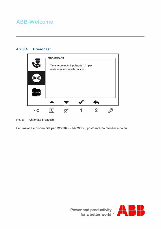
ABB-Welcome
4.2.3.4 Broadcast
Fig. 6: Chiamata broadcast
La funzione è disponibile per M22302-. / M22303-., posto interno monitor a colori.
BROADCAST
Tenere premuto il pulsante “√“ peravviare la funzione broadcast

ABB-Welcome
4.2.3.5 Attuatore
Fig. 7: Attuatore
Le liste attuatori devono essere prima impostate nel menu "Impostazione sistema - Attuatore".
Dopo aver selezionato un attuatore dalla lista, premere il pulsante √ per abilitare il blocco o la luce dacollegare all'attuatore.
ATTUATORE
Attuatore 1 (001)

ABB-Welcome
4.3 Impostazioni4.3.1 PanoramicaPremere il pulsante per accedere al menu di impostazione del sistema. Sono disponibili le seguentifunzioni:
N° Funzione1 Impostazioni intercomunicante
-Attivare chiamate intercomunicanti tra i diversi appartamenti o all'internodello stesso appartamento
2 Attuatore-Attivare attuatori da gestire nel sistema
3 Pulsante programmabile-Impostare le funzioni dei pulsanti programmabili
4 Inoltro chiamata-Impostare il destinatario (ad es. altri interni o portinerie) a cui si desidera inoltrare la chiamata dei visitatori quando non si è in casa.
5 Sblocco automatico-Impostare l'intervallo di tempo per lo sblocco automatico
6 Impostazione password posto esterno-Impostare la password apri-porta personalizzata, disponibile insieme allaSoluzione a tastiera del posto esterno.
7 Suoneria-Impostare la suoneria per l'esterno, campanello di piano o altro
8 Volume-Impostare il volume della suoneria
9 Data e ora-Impostazione orario e data
10 Altre impostazioni-Altre impostazioni, ad es. schermo intero automatico
11 Blacklist-Impostare la blacklist utilizzata per bloccare chiamate indesiderate da altriappartamenti
12 Archivio
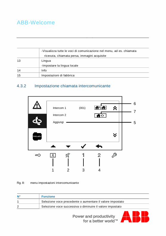
ABB-Welcome
-Visualizza tutte le voci di comunicazione nel menu, ad es. chiamataricevuta, chiamata persa, immagini acquisite
13 Lingua-Impostare la lingua locale
14 Info
15 Impostazioni di fabbricaPos: 27 /Di nA4 - A nleitu ngen Onlin e/Ueb ersc hrift en/3 ./Spr ech- und Videov erbi ndu ng @ 20\ mod _13 232 6236 870 0_1 5.do cx @ 1119 27 @ 3 @ 1
4.3.2 Impostazione chiamata intercomunicante
Fig. 8: menu impostazioni intercomunicante
N° Funzione1 Selezione voce precedente o aumentare il valore impostato
2 Selezione voce successiva o diminuire il valore impostato
1 2 3
6
4
5
Intercom 1 (001)
Intercom 2
AggiungiNuovo
7

ABB-Welcome
3 Confermare la selezione o modificarla
4 Tornare alla pagina precedente
5 Aggiungere una nuova lista intercomunicante. È possibile aggiungere unfino a 32 intercomunicanti complessivi.
6 Lista chiamate presenti. Premere il pulsante √ per modificarel'impostazione.
indica la chiamata esterna, la chiamata intercomunicante tra diversiappartamenti.
7 Lista chiamate presenti. Premere il pulsante √ per modificarel'impostazione.
indica la chiamata interna, la chiamata intercomunicante all'internodello stesso appartamento.
Aggiungi una nuova chiamata
Fig. 9: Aggiungi nuova chimata
1Tipochiamata
Chiamata esterna
Indirizzo
Rinomina
3
INTERCOM
001
mike
Salva Annulla
2

ABB-Welcome
N° Funzione1 Accedere per selezionare il tipo di chiamata:
-chiamata esterna significa chiamata tra appartamenti diversichiamata interna significa chiamata all'interno dello stesso appartamento
2 Accedere per modificare l'indirizzo da 001 a 250.*Se la chiamata è interna, non è necessario impostare l'indirizzo.
3 Rinominare la lista intercomunicanti:scorrere le lettere dell'alfabeto o i numeri, uno ad uno, con i pulsanti"+" o "-"
Al termine dell'impostazione, premere “Salva” per confermare.

ABB-Welcome
4.3.3 Impostazione attuatore
Fig. 10: Impostazione attuatore
3
4
ATTUATORE
Attuatore1
(001)
AggiungiNuovo
Indirizzo
Rinomina
002
di
Salva Annulla
ATTUATORE
2
1
Aggiungi un nuovo attuatore alla lista

ABB-Welcome
N° Funzione1 Lista attuatori presenti. Premere il pulsante √ per modificare le
impostazioni.
2 Aggiunge un nuovo attuatore alla lista. È possibile aggiungere fino a 10attuatori.
3 Accedere per modificare l'indirizzo da 001 a 199 con i pulsanti "+" o "-".
3 Rinominare la lista attuatori:scorrere le lettere dell'alfabeto o i numeri, uno ad uno, con i pulsanti "+" o "-"
4.3.4 Impostazione pulsante programmabile
Fig. 11: Impostazione pulsante programmabile
Pulsante 1 Sblocca
PULSANTEPROGRAMMABILE
Pulsante 2 N.D.
1
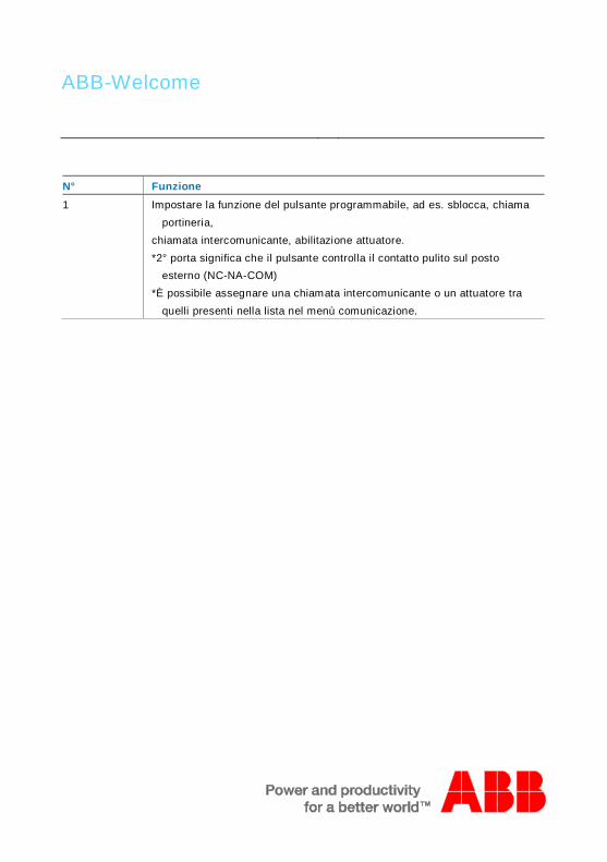
ABB-Welcome
N° Funzione1 Impostare la funzione del pulsante programmabile, ad es. sblocca, chiama
portineria,chiamata intercomunicante, abilitazione attuatore.*2° porta significa che il pulsante controlla il contatto pulito sul posto
esterno (NC-NA-COM)*È possibile assegnare una chiamata intercomunicante o un attuatore tra
quelli presenti nella lista nel menù comunicazione.

ABB-Welcome
4.3.5 Impostazione inoltro chiamata
Fig. 12: Impostazione inoltro di chiamata
N° Funzione1 Abilita/disabilita la funzione di inoltro chiamata
2 Accedere per selezionare il tipo di chiamata, interna o portineria
3 Accedere per modificare l'indirizzo se il tipo di chiamata è "Interna"*Se è attiva la funzione di inoltro chiamata, la funzione di sblocco automatico viene disabilitata.
*La funzione può essere impostata solo nel posto interno master.
*La funzione è disponibile per M22302-. / M22303-., posto interno a colori.
1
2
Inoltro chiamata
Tipochiamata
√
Interna
Salva Annulla
INOLTROCHIAMATA
Indirizzo 001 3

ABB-Welcome
4.3.6 Impostazione sblocco automatico
Fig. 13: Impostazione sblocco automatico
N° Funzione1 Abilita/disabilita la funzione di sblocco automatico
2 Abilita/disabilita lo sblocco automatico durante il periodo Tempo 1
3 Impostare l'ora di inizio e di fine del Tempo 1
4 Abilita/disabilita lo sblocco automatico durante il periodo Tempo 2
5 Impostare l'ora di inizio e di fine del Tempo 2*Attivando la funzione di sblocco automatico senza impostare l'ora esatta di attivazione, questafunzione sarà disponibile per 10 ore.
*Se è attiva la funzione di sblocco automatico, la funzione di inoltro chiamata viene disabilitata.
*La funzione può essere impostata solo nel posto interno master.
1Sblocco automatico
Tempo 1
2
SBLOCCO AUTOMATICO
√
√
08 00
17 00
:
:
Tempo 2 X
00 00
00 00
:
:
4
35

ABB-Welcome
4.3.7 Impostazione password posto esterno
Fig. 14: Impostazione password posto esterno
N° Funzione1 Abilita/disabilita la funzione password
2 Immettere la password utilizzando 6~8 caratteri*disponibile solo con posto esterno a tastiera.
*La funzione può essere impostata solo nel posto interno master.
1Attiva Password
InserisciPassword
IMPOSTA PASSWORD POSTO ESTERNO
√
123456 2

ABB-Welcome
4.3.8 Impostazione suoneria
Fig. 15: Suoneria
N° Funzione1 Selezionare la suoneria del campanello per il PE principale
2 Selezionare la suoneria del campanello per PE secondari
3 Selezionare la suoneria del campanello di piano per la portadell'appartamento
4 Selezionare la suoneria per altre funzioni, ad es. chiamata da portineria ochiamata intercomunicante da altri appartamenti.
1PE principale
PE secondari
Suoneria
Melodia 1
Melodia 2 2
Campanello Melodia 3
Altri Melodia 4
3
4

ABB-Welcome
4.3.9 Impostazione volume
Fig. 16: Impostazione volume
N° Funzione1 Impostazione del volume melodia
2 Abilita/disabilita il tono dei pulsanti.
1Volume suoneria
Tono pulsanti
VOLUME
Volume 3
2√

ABB-Welcome
4.3.10 Impostazione data e ora
Fig. 17: Impostazione data e ora
N° Funzione1 Impostazione data
2 Impostazione ora
3 Abilita/disabilita la funzione ora legale.*La funzione è disponibile per M22302-. / M22303-., posto interno monitor a colori.
1Data (AAAA-MM-GG)
Tempo
DATA E ORA
2013
208
Ora legale √
: 00
- 01 - 01
3

ABB-Welcome
4.3.11 Impostazione sistema di videocitofonia
Fig. 18: Impostazione sistema di videocitofonia
N° Funzione1 Abilita/disabilita la funzione di schermo intero automatico
2 Abilita/disabilita la funzione stato porta (disponibile solo con sensoreinstallato con l'esterno; lampeggia quando la porta è aperta)
3 Abilita/disabilita la funzione snapshot automatico*La funzione è disponibile per M22302-. / M22303-., posto interno monitor a colori.
4 Abilita/disabilita la funzione chiamata persa ( lampeggia in presenza diuna chiamata persa)
*La funzione è disponibile per M22302-. / M22303-., posto interno monitora colori.
1Schermo interoautomatico
Snapshot
SISTEMA DI VIDEOCITOFONIA
2Stato Porta
√
3
Chiamata
√
√
√ 4

ABB-Welcome
4.3.12 Impostazione blacklist
Fig. 19: Impostazione blacklist
Blacklist 1
Aggiungi
BLACKLIST
(001)
Indirizzo
BLACKLIST
Salva Annulla
002
1
2
3

ABB-Welcome
N° Funzione1 Voci presenti nella Blacklist. Premere il pulsante √ per modificare
l'impostazione.
2 Aggiunge una nuova voce alla blacklist. È possibile aggiungere un fino a 32voci alla blacklist complessive.
3 Accedere per modificare l'indirizzo da 001 a 250 con i pulsanti "+" o "-".*La funzione può essere impostata solo nel posto interno master.
*La funzione è disponibile per M22302-. / M22303-., posto interno monitor a colori.
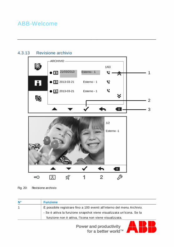
ABB-Welcome
4.3.13 Revisione archivio
Fig. 20: Revisione archivio
N° Funzione1 È possibile registrare fino a 100 eventi all'interno del menu Archivio.
- Se è attiva la funzione snapshot viene visualizzata un'icona. Se lafunzione non è attiva, l'icona non viene visualizzata.
●
ARCHIVIO
1/2
Esterno -1
1/6321/03/2013 Esterno - 1
● 2013-03-21 Esterno - 1
● 2013-03-21 Esterno - 1
1
2
3

ABB-Welcome
-Data, ora e tipo di evento vengono registrati insieme all’immagine.
2 Premere questo pulsante per visualizzare i dettagli dell'evento.Quando un visitatore suona al PE vengono registrate 2 immagini.
3 Premere questo pulsante per eliminare l'evento.*La funzione è disponibile per M22302-. / M22303-., posto interno monitor a colori.

ABB-Welcome
4.3.14 Impostazione della lingua
Fig. 21: Impostazione della lingua
4.3.15 Info
Fig. 22: Informazioni sul posto interno (scansione del QR code per avere informazioni dettagliatesul posto interno)
English
LINGUA
Français
Italiano
Português
Español
Versione Flash: V0.11_130723
INFO
Versione MCU: V0.11_130722
M/S: Master
PE di default: 1
Indirizzo PI: 001

ABB-Welcome
4.3.16 Ripristino delle impostazioni di fabbrica
Fig. 23: Ripristino delle impostazioni di fabbrica
N° Funzione1 Ripristino di tutte le impostazioni:
Resetta il dispositivo e ripristina tutte configurazioni allo stato di fabbrica.Questa operazione non elimina i dati programmati e l'archivio, ad es. leliste intercom., le liste attuatori, ecc.
2 Cancella tutti i dati:Cancella tutti i dati programmati e l'archivio. Anche le configurazioni
verrano resettate alle impostazioni di default.
RIPRISTINO DELLE IMPOSTAZIONIDI DEFAULT
Resettare?
Annulla OK
Ripristino di tutte leimpostazioni
Cancella tutti i dati. ×
√

ABB-Welcome
Pos: 67 /Di nA4 - A nleitu ngen Onlin e/Ueb ersc hrift en/2 ./Reini gung @ 1 9\m od_ 131 0733 980 533 _15. docx @ 10 785 3 @ 2 @ 1
4.4 PuliziaPos: 68 /Di nA4 - A nleitu ngen Onlin e/In halt/KNX/Do orEnt ry/Reini gun g/Reini gun g Touchsc ree nm onito r @ 19\m od_ 131 073 410 897 8_15 .docx @ 1 078 62 @ @ 1
Attenzione
Rischio di danneggiamento della superficie dello schermo.
Oggetti duri o appuntiti possono danneggiare la superficie delloschermo.Non servirsi di oggetti simili per l'utilizzo del touch screen.– Usare le dita o uno stilo di plastica.
Prodotti per la pulizia e agenti abrasivi possono danneggiare lasuperficie dello schermo.– Pulire le superfici con un panno morbido e un detergente vetri in
commercio.– Non utilizzare prodotti di pulizia abrasivi.
Pos: 69 /B usch-J aeg er (Neus truk tur )/M odul -Strukt ur/O nline -Doku me ntatio n/Steu er mod ule - Onlin e-Dok ume ntati on ( -- > Für alle Dok ume nte <- -)/ +++ ++ ++ +++ ++ S eiten umb ruch + +++ ++ ++ +++ + @ 9\m od_ 126 8898 668 093 _0. docx @ 521 49 @ @ 1

ABB-Welcome
Pos: 70 /Di nA4 - A nleitu ngen Onlin e/Ueb ersc hrift en/2 ./Ge raet eeins tellun gen @ 1 8\mo d_1 302 768 847 744 _15. docx @ 10 354 8 @ 2 @ 1
4.5 Impostazione del dispositivoPos: 71 /Di nA4 - A nleitu ngen Onlin e/Ueb ersc hrift en/3 ./Abschl usswide rsta nd @ 19\ mod _13 219 5807 990 6_1 5.do cx @ 1100 83 @ 3 @ 1
Pos: 72 /Di nA4 - A nleitu ngen Onlin e/In halt/KNX/Do orEnt ry/Bedie nun g/Abschl usswide rsta nd s etzen 83 220 -AP-xxx @ 19\ mod _13 1072 339 236 9_1 5.do cx @ 1 078 41 @ @ 1
Fig. 24:
Pos: 74 /Di nA4 - A nleitu ngen Onlin e/In halt/KNX/Do orEnt ry/Bedie nun g/M aste r/Slave Sc halte r setz en 832 20-AP-xxx @ 1 9\m od_1 310 723 320 966 _15. docx @ 10 783 3 @ @
1. Posto
Jumper per impostare l'indirizzo del PE principale.
2. X100 X10 X1Jumper per impostare l'indirizzo del posto interno.
ESEMPIO: impostazione indirizzo 024.
3. Funzione Master/SlavePer ogni appartamento è possibile impostare un solo posto interno come "Master"
(Jumper da impostare come 'M/S on'). Tutti gli altri posti interni nello stesso

ABB-Welcome
appartamento devono essere impostati come "Slave" (Jumper da impostare come'M/S off').
4. Resistenza terminale di chiusuraNegli impianti video o impianti misti audio/video, il Jumper deve essere impostato
come 'RC on' sull'ultimo dispositivo di linea.
5. a b = Connessione Bus= Collegamento campanello
DC GND = Alimentazione supplementare
Pos: 75 /B usch-J aeg er (Neus truk tur )/M odul -Strukt ur/O nline -Doku me ntatio n/Steu er mod ule - Onlin e-Dok ume ntati on ( -- > Für alle Dok ume nte <- -)/ +++ ++ ++ +++ ++ S eiten umb ruch + +++ ++ ++ +++ + @ 9\m od_ 126 8898 668 093 _0. docx @ 521 49 @ @ 1

ABB-Welcome
Pos: 76 /Di nA4 - A nleitu ngen Onlin e/Ueb ersc hrift en/1 ./Technisc he D aten @ 18 \mo d_1 302 615 863 001 _15. docx @ 10 341 6 @ 1 @ 1
5 Dati tecniciPos: 77 /Di nA4 - A nleitu ngen Onlin e/In halt/KNX/Do orEnt ry/83 220 -AP-xxx/ Tech nische Date n - 832 20-AP-x xx @ 1 8\m od_ 130 321 285 4559 _15 .docx @ 1 037 05 @ @ 1
Denominazione ValoreRisoluzione display: 480 x 272Dimensione display 4.3”
Temperatura di funzionamento -10° C- +55° C
Temperatura di stoccaggio -40° C – +70° C
Protezione IP 30
Morsetti a filo singolo 2 x 0,6 mm² – 2 x 1 mm²
Morsetti a filo sottile 2 x 0,6 mm² – 2 x 0,75 mm²
Tensione del bus 20-30 V
Pos: 78 /B usch-J aeg er (Neus truk tur )/M odul -Strukt ur/O nline -Doku me ntatio n/Steu er mod ule - Onlin e-Dok ume ntati on ( -- > Für alle Dok ume nte <- -)/ +++ ++ ++ +++ ++ S eiten umb ruch + +++ ++ ++ +++ + @ 9\m od_ 126 8898 668 093 _0. docx @ 521 49 @ @ 1

ABB-Welcome
Pos: 79 /B usch-J aeg er (Neus truk tur )/M odul -Strukt ur/O nline -Doku me ntatio n/Übe rsch rifte n ( --> Fü r alle Doku men te < -- )/1. E bene /M - O/ Mont age / Ins tallatio n @ 18\ mod _13 0261 396 611 1_1 5.do cx @ 1 033 73 @ 1 @ 1
6 Montaggio/InstallazionePos: 80 /B usch-J aeg er (Neus truk tur )/M odul -Strukt ur/O nline -Doku me ntatio n/Siche rheit (- -> Fü r alle D oku ment e < --) /War nhinweis e/Siche rheit - Nie ders pan nun gs- und 230 V-Leit ung en @ 18\ mod _13 026 178 214 91_1 5.d ocx @ 103 465 @ @ 1
Attenzione
Tensione elettrica!
Rischio di morte ed incendio dovuto alla presenza di tensione elettrica100-2100-240 V.– Non installare contemporaneamente i cavi di bassa tensione e
i cavi 100-240 V in una presa da incasso!Pericolo di carico da 100-240 V sulla linea a bassa tensione incaso di cortocircuito.
Pos: 81 /B usch-J aeg er (Neus truk tur )/M odul -Strukt ur/O nline -Doku me ntatio n/Siche rheit (- -> Fü r alle D oku ment e < --) /War nhinweis e/Siche rheit - Fachk enn tnisse @ 18 \mo d_1 302 774 384 017_ 15. docx @ 10 356 4 @ 2 @ 1

ABB-Welcome
6.1 Obblighi dell'elettricista
Attenzione
Tensione elettrica!
L'installazione del dispositivo può essere effettuata solo se si disponedelle necessarie competenze ed esperienze in campo elettrico.• Un'installazione non corretta mette a rischio la vostra vita e
quella dell'utente dell'impianto elettrico.• Un'installazione non corretta può causare gravi danni materiali, ad
esempio a seguito di un incendio.Di seguito vengono specificati il livello minimo di competenze tecniche
e i requisiti necessari per poter procedere all'installazione:• Applicare le "cinque regole di sicurezza" (DIN VDE 0105, EN
50110):1. Scollegare;2. Accertarsi che non sia possibile un reinserimentoaccidentale;3. Verificare l'assenza di tensione;4. Collegare a terra;5. Coprire o proteggere parti adiacenti sotto tensione.
• Indossare indumenti di protezione personale adeguati.• Utilizzare solo attrezzi e strumenti di misura adeguati.• Controllare il tipo di sistema di distribuzione (sistema TN, IT, TT)
per garantire le seguenti condizioni di alimentazione elettrica(messa a terra tradizionale, messa a terra di protezione, misure diprotezione aggiuntive, ecc.).
Pos: 82 /Di nA4 - A nleitu ngen Onlin e/In halt/KNX/Do orEnt ry/M onta ge/ Mont age hinweis e - Allg emei n @ 1 9\m od_ 131 056 367 047 8_15 .docx @ 1 077 43 @ 2 @ 1

ABB-Welcome
6.2 Istruzioni generali di installazione• Terminare tutte le tratte del sistema del sistema di cablaggio con un
dispositivo bus collegato (ad es. posto interno, posto esterno, dispositivodi sistema).
• Non installare la centrale di sistema vicino al trasformatore campanello ealle altre fonti di alimentazione (per evitare interferenze).
• Non installare i fili del bus di sistema insieme ai fili 100-240 V.• Non usare cavi tradizionali per i fili di collegamento degli apriporta e del
bus di sistema.• Non collegare in parallelo cavi di diverso tipo.• Usare solo due fili nel cavo quadripolare o multipolare del bus di sistema.• In fase di collegamento, non installare il bus in entrata e in uscita
all'interno dello stesso cavo.• Non installare il bus interno ed esterno nello stesso cavo.Pos: 83 /B usch-J aeg er (Neus truk tur )/M odul -Strukt ur/O nline -Doku me ntatio n/Steu er mod ule - Onlin e-Dok ume ntati on ( -- > Für alle Dok ume nte <- -)/ +++ ++ ++ +++ ++ S eiten umb ruch + +++ ++ ++ +++ + @ 9\m od_ 126 8898 668 093 _0. docx @ 521 49 @ @ 1

ABB-Welcome
Pos: 84 /B usch-J aeg er (Neus truk tur )/M odul -Strukt ur/O nline -Doku me ntatio n/Übe rsch rifte n ( --> Fü r alle Doku men te < -- )/2. E bene /M - O/ Mont age @ 1 8\m od_1 302 615 960 458 _15. docx @ 10 342 4 @ 2 @ 1
6.3 MontaggioPos: 85. 1 /DinA4 - Anleit ung en O nline/I nhal t/KNX/DoorE ntry/ 832 20-AP-xxx /Mo nta ge - Mo dule/ Mon tag e - Mon tage dos e -- 83 220 -AP-xxx @ 19\ mod _132 325 040 684 8_1 5.doc x @ 1 110 98 @ @ 1
Altezza di installazione consigliata
Smontaggio
Aprire l'alloggiamento del pannello premendo il gancio sul fondo del dispositivo.
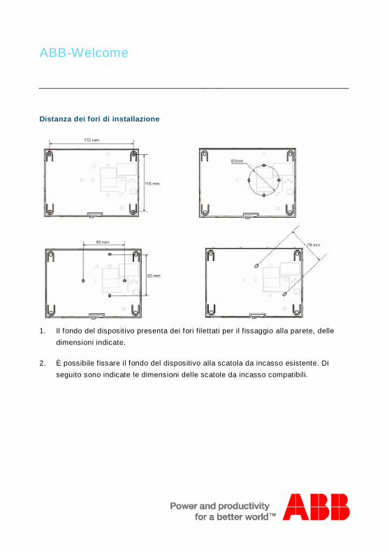
ABB-Welcome
Distanza dei fori di installazione
1. Il fondo del dispositivo presenta dei fori filettati per il fissaggio alla parete, delledimensioni indicate.
2. È possibile fissare il fondo del dispositivo alla scatola da incasso esistente. Diseguito sono indicate le dimensioni delle scatole da incasso compatibili.
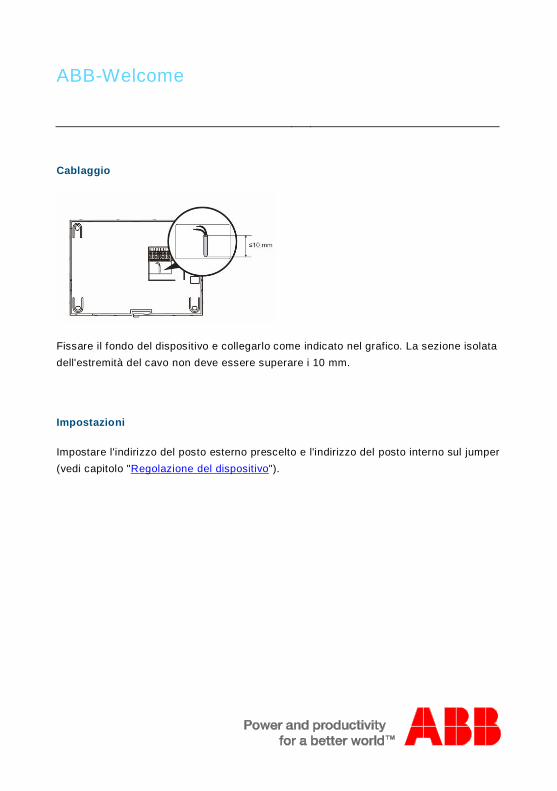
ABB-Welcome
Cablaggio
Fissare il fondo del dispositivo e collegarlo come indicato nel grafico. La sezione isolatadell'estremità del cavo non deve essere superare i 10 mm.
Impostazioni
Impostare l'indirizzo del posto esterno prescelto e l'indirizzo del posto interno sul jumper(vedi capitolo "Regolazione del dispositivo").

ABB-Welcome
Montaggio a parete
1. Fissare il fondo del dispositivo alla parete.
2. Fissare la parte superiore del dispositivo alla parte inferiore del dispositivo (fondo).A tal scopo, posizionare il lato superiore del dispositivo sulle linguette e premere illato inferiore sul fondo del dispositivo, fino a che la chiusura si inserisca a scatto.
Montaggio con scatola da incasso

ABB-Welcome
1. Fissare il fondo del dispositivo alla scatola da incasso esistente.
2. Fissare la parte superiore del dispositivo alla parte inferiore del dispositivo (fondo).A tal scopo, posizionare il lato superiore del dispositivo sulle linguette e premere illato inferiore sul fondo del dispositivo, fino a che la chiusura si inserisca a scatto.
Montaggio con staffa desktop
1. Fissare il fondo del dispositivo alla staffa desktop.
2. Fissare la parte superiore del dispositivo alla parte inferiore del dispositivo (fondo).A tal scopo, posizionare il lato superiore del dispositivo sulle linguette e premere illato inferiore sul fondo del dispositivo, fino a che la chiusura si inserisca a scatto.
L'installazione del posto interno è completata.
os: 94 /Busch -Jae ger (Ne ustru ktur )/M odul -Struk tur/ Onlin e-Dok ume ntati on/Ste uer mod ule - Onlin e-Do kum enta tion (-- > Für alle Do kum ente <- -)/ ++ ++ +++ ++ ++ + Seite num bruc h + ++ +++ ++ ++ ++ @ 9\ mod _126 889 866 809 3_0. docx @ 52 149 @ @ 1

ABB-Welcome
Pos: 95 /Di nA4 - A nleitu ngen Onlin e/In halt/KNX/Do orEnt ry/Proj ektier ung -M erkbl att/Pr ojektie rPos: 9 7 /Busc h-Ja ege r (N eust ruktu r)/ Mo dul-Str uktu r/Onli ne-D oku ment ation /Rückseit en (-- > Für alle Dok um ente <- -)/R ückseit e - Bus ch-J aeg er - Allgem ein @ 20\ mod _13 273 200 748 86_1 5.d ocx @ 137 103 @ @ 1
Avvertenza=== E nde der Liste für Tex tma rke Ba ckcove r = ==
Ci riserviamo il diritto di apportare, in qualsiasi momento, modifiche tecniche omodificare il contenuto del presente documento senza preavviso.Le specifiche dettagliate concordate al momento dell'ordine si applicano a tutti gli ordini.ABB declina ogni responsabilità per eventuali errori o incompletezze in questodocumento. Ci riserviamo tutti i diritti del presente documento, degli argomenti e delle illustrazioniivi contenute. È vietata la riproduzione, la divulgazione a terzi o l'utilizzo dei relativicontenuti in toto o in parte, senza il previo consenso scritto da parte di ABB.

VER:1.0 │ │ 14.07.2014
Urządzenie ABB-Welcome M
Pos: 2 /DinA4 - Anl eitun gen Online /Inh alt/KNX/Doo rEntry /832 20-AP- xxx/Tit elblat t - 832 20-AP-xxx - ABB @ 1 9\m od_ 132 3249 806 476 _15. docx @ 11 108 4 @ @ 1
M22301-.M22302-.M22303-.Zestaw wideo 4,3" zesłuchawkąstacja zewnętrzna
=== E nde der Liste für Tex tma rke C over == =

ABB-Welcome
| — 2 —
Pos: 4 /Busc h-Ja ege r (N eust rukt ur)/ Mo dul-St ruktu r/Onli ne-D oku ment ation /Inh altsve rzeich nis ( --> Fü r alle Doku men te <-- )/In haltsve rzeic hnis @ 19\ mod _13 206 490 4438 6_1 5.d ocx @ 109 653 @ @ 1
1 Bezpieczeństwo ........................................................................................ 32 Przeznaczenie .......................................................................................... 33 Środowisko ............................................................................................... 3
3.1 Urządzenia ABB ........................................................................ 34 Działania ................................................................................................... 5
4.1 Operacje standardowe .............................................................. 54.1.1 Elementy sterujące .................................................................... 54.2 Elementy sterujące .................................................................... 94.2.1 Połączenia przychodzące / Podczas połączenia ......................... 94.2.2 Ustawienia wyświetlacza i głośności podczas połączenia ......... 114.2.3 Menu komunikacji ................................................................... 124.3 Ustawienia .............................................................................. 154.3.1 Przegląd ................................................................................. 154.3.2 Ustawienia połączenia przez interkom ..................................... 164.3.3 Ustawienia siłownika przełącznika ........................................... 184.3.4 Ustawienia przycisku programowalnego................................... 194.3.5 Ustawianie przekierowania połączeń........................................ 204.3.6 Ustawienia automatycznego zwalniania blokady ...................... 214.3.7 Ustawienia hasła stacji zewnętrznej ......................................... 224.3.8 Ustawienia dzwonka................................................................ 234.3.9 Ustawienia głośności ............................................................... 244.3.10 Ustawienia daty i godziny ........................................................ 254.3.11 Ustawienia systemu domofonowego ........................................ 264.3.12 Ustawienia listy zastrzeżeń ...................................................... 274.3.13 Przeglądanie historii ................................................................ 294.3.14 Ustawienia języka ................................................................... 314.3.15 Informacje ............................................................................... 314.3.16 Resetowanie do ustawień fabrycznych ..................................... 324.4 Czyszczenie............................................................................ 334.5 Regulacja urządzenia .............................................................. 34
5 Dane techniczne ..................................................................................... 356 Montaż / instalacja .................................................................................. 36
6.1 Wymagania wobec elektryków ................................................. 366.2 Ogólna instrukcja montażu ...................................................... 376.3 Montaż ................................................................................... 38
=== E nde der Liste für Tex tma rke TOC == =

ABB-Welcome
| — 3 —
Pos: 6 /Busc h-Ja ege r (N eust rukt ur)/ Mo dul-St ruktu r/Onli ne-D oku ment ation /Übe rschri ften (- -> Für alle D okum ent e < --)/ 1. Eb ene/S - T /Sicher heit @ 18\ mod _13 026 127 917 90_ 15.d ocx @ 103 357 @ 1 @ 1
1 BezpieczeństwoPos: 7 /Busc h-Ja ege r (N eust rukt ur)/ Mo dul-St ruktu r/Onli ne-D oku ment ation /Sicher heit (-- > Für alle Dok um ente <- -)/Wa rn hinweise /Sicher heit - 23 0 V @ 18\m od_ 130 260 681 675 0_15 .docx @ 1 033 08 @ @ 1
OstrzeżenieNapięcie elektryczne!Ryzyko śmierci i pożaru z powodu napięcia elektrycznego równego 100–240 V.– Prace przy układzie zasilania o mocy 100–240 V mogą być
wykonywane tylko przez uprawnionych elektryków!– Odłączyć zasilanie elektryczne przed instalacją lub demontażem!
Pos: 8 /Busc h-Ja ege r (N eust rukt ur)/ Mo dul-St ruktu r/Onli ne-D oku ment ation /Übe rschri ften (- -> Für alle D okum ent e < --)/ 1. Eb ene/A - F /Bestim mun gsge mä ßer Geb rau ch @ 18\ mod _13 027 6332 131 6_1 5.do cx @ 1034 83 @ 1 @ 1
2 PrzeznaczeniePos: 9 /DinA4 - Anl eitun gen Online /Inh alt/KNX/Doo rEntry /832 20-AP- xxx/Besti mmu ngsg em aesse r Ge bra uch - 83 220 -AP-xxx- 500 @ 2 0\mo d_1 324 561 168 699 _15. docx @ 11 272 8 @ @ 1
Urządzenie M2230x-x stanowi integralną część systemu domofonowego ABB WelcomeM, działającą wyłącznie z elementami tego systemu. Urządzenie można instalować tylkow suchych pomieszczeniach wewnątrz budynku.
Pos: 10 /B usch-J aeg er (Neus truk tur )/M odul -Strukt ur/O nline -Doku me ntatio n/Übe rsch rifte n ( --> Fü r alle Doku men te < -- )/1. E bene /U - Z/U mwelt @ 18\ mod _13 026 141 5896 7_1 5.d ocx @ 103 383 @ 1 @ 1
3 ŚrodowiskoPos: 11 /B usch-J aeg er (Neus truk tur )/M odul -Strukt ur/O nline -Doku me ntatio n/Umw elt ( --> Für all e Doku me nte <-- )/Hinweis e/Hinw eis - U mwelt - Hinweis Elektr oge räte @ 1 8\mo d_1 302 763 973 434 _15. docx @ 10 350 0 @ @ 1
Ochrona środowiska!Nie można wyrzucać urządzeń elektrycznych ani elektronicznych zodpadami z gospodarstwa domowego.– Urządzenie zawiera cenne surowce, które można ponownie
wykorzystać. Dlatego należy je oddać do odpowiedniego punktuzbiórki.
Pos: 12 /Di nA4 - A nleitu ngen Onlin e/Ueb ersc hrift en/2 ./ABB Gera ete @ 19 \mo d_1 323 162 843 832_ 15. docx @ 11 087 5 @ 2 @ 1
3.1 Urządzenia ABBPos: 13 /B usch-J aeg er (Neus truk tur )/M odul -Strukt ur/O nline -Doku me ntatio n/Umw elt ( --> Für all e Doku me nte <-- )/Hinweis e/Hinw eis - U mwelt - ABB Elektro ger äte @ 19\ mo d_1 3231 627 458 39_ 15.d ocx @ 110 867 @ @ 1
Na wszystkich materiałach pakunkowych i urządzeniach firmy ABB znajdują sięoznakowania i symbole atestujące dotyczące ich właściwej utylizacji. Materiałypakunkowe i urządzenia elektryczne, jak również ich elementy należy zawsze oddawaćdo utylizacji w autoryzowanych punktach zbiórki lub zakładach utylizacji odpadów.

ABB-Welcome
| — 4 —
Produkty firmy ABB spełniają wymogi prawne i są w szczególności zgodne z ustawami ourządzeniach elektrycznych i elektronicznych oraz rozporządzeniem REACH.(Dyrektywa UE 2002/96/EG WEEE i RoHS 2002/95/WE)(Rozporządzenie UE REACH i ustawa wykonawcza do rozporządzenia (WE) nr1907/2006)

ABB-Welcome
| — 5 —
Pos: 18 /Di nA4 - A nleitu ngen Onlin e/Ueb ersc hrift en/1 ./Bedie nun g @ 18\m od_ 130 261 392 416 5_15 .docx @ 1 033 65 @ 1 @ 1
4 DziałaniaPos: 19 /Di nA4 - A nleitu ngen Onlin e/Ueb ersc hrift en/2 ./Nor male r Bet rieb @ 18 \mo d_1 302 768 8209 65_ 15. docx @ 10 3540 @ 2 @ 1
4.1 Operacje standardowePos: 20 /Di nA4 - A nleitu ngen Onlin e/Ueb ersc hrift en/3 ./Bedie nele men te @ 20\ mod _13 232 6022 055 9_1 5.do cx @ 1 116 47 @ 3 @ 1
4.1.1 Elementy sterującePos: 21 /Di nA4 - A nleitu ngen Onlin e/In halt/KNX/Do orEnt ry/83 220 -AP-xxx/Be dienel eme nte - 8 322 0-AP-xxx @ 18\ mo d_1 3032 128 536 05_ 15.d ocx @ 103 673 @ @ 1
Rys. 1 Elementy sterujące
12
3
9
4 5 6 7 8
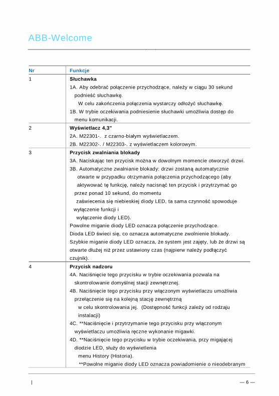
ABB-Welcome
| — 6 —
Nr Funkcje1 Słuchawka
1A. Aby odebrać połączenie przychodzące, należy w ciągu 30 sekundpodnieść słuchawkę.
W celu zakończenia połączenia wystarczy odłożyć słuchawkę.1B. W trybie oczekiwania podniesienie słuchawki umożliwia dostęp do
menu komunikacji.
2 Wyświetlacz 4,3"2A. M22301-. z czarno-białym wyświetlaczem.2B. M22302-. / M22303-. z wyświetlaczem kolorowym.
3 Przycisk zwalniania blokady3A. Naciskając ten przycisk można w dowolnym momencie otworzyć drzwi.3B. Automatyczne zwalnianie blokady: drzwi zostaną automatycznie
otwarte w przypadku otrzymania połączenia przychodzącego (abyaktywować tę funkcję, należy nacisnąć ten przycisk i przytrzymać go
przez ponad 10 sekund, do momentuzaświecenia się niebieskiej diody LED, ta sama czynność spowoduje
wyłączenie funkcji iwyłączenie diody LED).
Powolne miganie diody LED oznacza połączenie przychodzące.Dioda LED świeci się, co oznacza automatyczne zwolnienie blokady.Szybkie miganie diody LED oznacza, że system jest zajęty, lub że drzwi sąotwarte dłużej niż przez ustawiony czas (najpierw należy podłączyćczujnik).
4 Przycisk nadzoru4A. Naciśnięcie tego przycisku w trybie oczekiwania pozwala na
skontrolowanie domyślnej stacji zewnętrznej.4B. Naciśnięcie tego przycisku przy włączonym wyświetlaczu umożliwia
przełączenie się na kolejną stację zewnętrznąw celu skontrolowania jej. (Dostępność funkcji zależy od rodzajuinstalacji)
4C. **Naciśnięcie i przytrzymanie tego przycisku przy w łączonymwyświetlaczu umożliwia ręczne wykonanie migawki.
4D. **Naciśnięcie tego przycisku w trybie oczekiwania, przy migającejdiodzie LED, służy do wyświetlenia
menu History (Historia). **Powolne miganie diody LED oznacza powiadomienie o nieodebranym

ABB-Welcome
| — 7 —
połączeniu.
5 Przycisk wyciszenia5A. Naciśnięcie tego przycisku w trybie oczekiwania pozwala nawyciszenie dzwonka tej stacji
wewnętrznej.5B. Naciśnięcie i przytrzymanie tego przycisku w trybie oczekiwania
pozwala na wyciszenie dzwonków wszystkich stacji wewnętrznych wmieszkaniu.
stacji wewnętrznych w mieszkaniu.5C. Podczas połączenia przychodzącego naciśnięcie tego przycisku
powoduje odrzucenie tego połączenia.5D. Naciśnięcie tego przycisku w czasie rozmowy powoduje wyciszenie
mikrofonu.Dioda LED świeci się, co oznacza wyciszenie.
6 Przycisk programowalny 16A. Odblokowanie zamka podłączonego do stacji zewnętrznej (COM-NC-
NO)(funkcja domyślna).
6B. Naciśnięcie tego przycisku w trybie oczekiwania i przytrzymanie goprzez 3 sekundy umożliwia wysłanie alarmu SOS do konsoli portierskiej.
do konsoli portierskiej. Powolne miganie diody LED oznacza, że sygnałzostał wysłany,
natomiast szybkie miganie oznacza, że operacja nie powiodła się.6C. *Możliwość zaprogramowania dodatkowej funkcji, np. połączenie z
konsolą portierską, interkom.....
7 Przycisk programowalny 2*Możliwość zaprogramowania dodatkowej funkcji, np. połączenie z konsolą
portierską, interkom....
8 Przycisk ustawień systemowychPozwala na przejście do ustawień systemowych i uzyskanie dostępu do
różnych funkcji urządzenia.Szybkie miganie diody LED oznacza, że ustawienie jest zajęte.
9 ***Funkcja pętli indukcyjnej*W celu zapoznania się z ich zastosowaniem należy skontaktować się z instalatorem
instalacji elektrycznej.
**Funkcja jest dostępna w modelu M22302-. /M22303-., kolorowa stacja wewnętrzna wideo ze
słuchawką.
ABB-Welcome
| — 8 —
***Ta funkcja jest dostępna tylko w modelu M22303-.Pos: 22 /B usch-J aeg er (Neus truk tur )/M odul -Strukt ur/O nline -Doku me ntatio n/Steu er mod ule - Onlin e-Dok ume ntati on ( -- > Für alle Dok ume nte <- -)/ +++ ++ ++ +++ ++ S eiten umb ruch + +++ ++ ++ +++ + @ 9\m od_ 126 8898 668 093 _0. docx @ 521 49 @ @ 1

ABB-Welcome
| — 9 —
Pos: 26 /Di nA4 - A nleitu ngen Onlin e/Ueb ersc hrift en/2 ./Bedie nakti onen @ 2 0\m od_ 1323 262 294 281 _15. docx @ 11 191 1 @ 2 @ 1
4.2 Elementy sterującePos: 27 /Di nA4 - A nleitu ngen Onlin e/Ueb ersc hrift en/3 ./Spr ech- und Videov erbi ndu ng @ 20\ mod _13 232 6236 870 0_1 5.do cx @ 1119 27 @ 3 @ 1
4.2.1 Połączenia przychodzące / Podczas połączeniaPos: 28 /Di nA4 - A nleitu ngen Onlin e/In halt/KNX/Do orEnt ry/83 220 -AP-xxx/Sp rech - u nd Vide over bind ung - 8 322 0-AP-xxx @ 20\ mo d_1 3232 623 418 52_ 15.d ocx @ 111 919 @ @ 1
Fig. 2 Połączenia przychodzące / Podczas połączeniaPodczas połączenia przychodzącego dostępne są następujące funkcje:Nr Funkcje1 Odbieranie połączenia przychodzącego następuje po podniesieniu
słuchawki. Aby zakończyć połączenie, należy odłożyć słuchawkę.
2 Naciśnięcie tego przycisku powoduje otwarcie drzwi, z których pochodzipołączenie.
3-A Naciśnięcie tego przycisku pozwala na skontrolowanie kamery analogowejw stacji zewnętrznej, jeżeli
taka istnieje.3-B Naciśnięcie i przytrzymanie tego przycisku powoduje wykonanie migawki.
*Funkcja jest dostępna w modelu M22302-. /M22303-., kolorowa stacjawewnętrzna wideo ze słuchawką.
4 Naciśnięcie tego przycisku powoduje wyciszenie dźwięku dzwonkapołączenia przychodzącego; naciśnięcie
tego przycisku podczas połączenia spowoduje wyciszenie mikrofonu.5-A Naciśnięcie tego przycisku powoduje aktywację funkcji przycisku
30sOutdoor 1
2 4 6
7
8
3 51
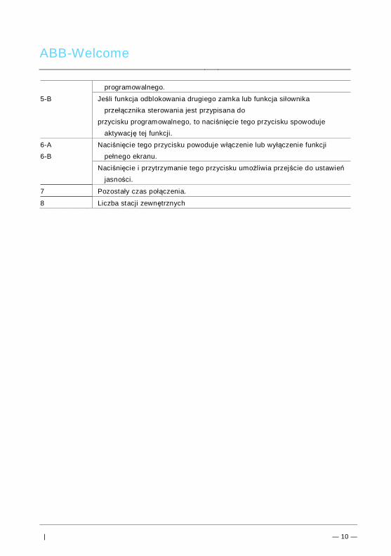
ABB-Welcome
| — 10 —
programowalnego.
5-B Jeśli funkcja odblokowania drugiego zamka lub funkcja siłownikaprzełącznika sterowania jest przypisana do
przycisku programowalnego, to naciśnięcie tego przycisku spowodujeaktywację tej funkcji.
6-A6-B
Naciśnięcie tego przycisku powoduje w łączenie lub wyłączenie funkcjipełnego ekranu.
Naciśnięcie i przytrzymanie tego przycisku umożliwia przejście do ustawieńjasności.
7 Pozostały czas połączenia.
8 Liczba stacji zewnętrznychPos: 29 /B usch-J aeg er (Neus truk tur )/M odul -Strukt ur/O nline -Doku me ntatio n/Steu er mod ule - Onlin e-Dok ume ntati on ( -- > Für alle Dok ume nte <- -)/ +++ ++ ++ +++ ++ S eiten umb ruch + +++ ++ ++ +++ + @ 9\m od_ 126 8898 668 093 _0. docx @ 521 49 @ @ 1
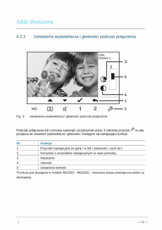
ABB-Welcome
| — 11 —
Pos: 30 /Di nA4 - A nleitu ngen Onlin e/Ueb ersc hrift en/3 ./Tuer oeff nen @ 2 0\mo d_1 323 263 277 453 _15. docx @ 11 193 5 @ 3 @ 1
4.2.2 Ustawienia wyświetlacza i głośności podczas połączeniaPos: 31 /Di nA4 - A nleitu ngen Onlin e/In halt/KNX/Do orEnt ry/83 220 -AP-xxx/ Tue r o effne n - 832 20-AP-x xx @ 20\m od_ 132 326 795 847 9_15 .docx @ 1 121 09 @ @ 1
Fig. 3 Ustawienia wyświetlacza i głośności podczas połączenia
Podczas połączenia lub rozmowy nacisnąć i przytrzymać przez 3 sekundy przycisk w celuprzejścia do ustawień wyświetlacza i głośności. Dostępne są następujące funkcje.
Nr Funkcje1 Przyciski nawigacyjne (w górę / w dół / potwierdź / usuń itd.)
2 Korzystać z przycisków nawigacyjnych w razie potrzeby.
3 Nasycenie
4 Jasność
5 Ustawiona wartość
*Funkcja jest dostępna w modelu M22302-. /M22303-., kolorowa stacja wewnętrzna wideo zesłuchawką.
Pos: 32 /B usch-J aeg er (Neus truk tur )/M odul -Strukt ur/O nline -Doku me ntatio n/Steu er mod ule - Onlin e-Dok ume ntati on ( -- > Für alle Dok ume nte <- -)/ +++ ++ ++ +++ ++ S eiten umb ruch + +++ ++ ++ +++ + @ 9\m od_ 126 8898 668 093 _0. docx @ 521 49 @ @ 1
120sOutdoor 1
23
4
5
1
2

ABB-Welcome
| — 12 —
Pos: 33 /Di nA4 - A nleitu ngen Onlin e/Ueb ersc hrift en/3 ./Stum m sc halte n @ 2 0\m od_ 132 326 360 7142 _15 .docx @ 1 119 51 @ 3 @ 1Pos: 66 /B usch-J aeg er (Neus truk tur )/M odul -Strukt ur/O nline -Doku me ntatio n/Steu er mod ule - Onlin e-Dok ume ntati on ( -- > Für alle Dok ume nte <- -)/ +++ ++ ++ +++ ++ S eiten umb ruch + +++ ++ ++ +++ + @ 9\m od_ 126 8898 668 093 _0. docx @ 521 49 @ @ 1
4.2.3 Menu komunikacjiPos: 31 /Di nA4 - A nleitu ngen Onlin e/In halt/KNX/Do orEnt ry/83 220 -AP-xxx/ Tue r o effne n - 832 20-AP-x xx @ 20\m od_ 132 326 795 847 9_15 .docx @ 1 121 09 @ @ 1
4.2.3.1 PrzeglądPodniesienie słuchawki powoduje przejście do menu komunikacji. Dostępne są następującefunkcje:Nr Funkcje1 Połączenie przez interkom
– Aby wykonać połączenie przez interkom, należy dotknąć istniejącej listypołączeń.
2 Połączenie z konsolą portierską– Bezpośrednie połączenie z konsolą portierską.
3 Nadawanie– W łączanie funkcji nadawania w tym menu
4 Siłownik przełącznika– Aktywowanie listy istniejących siłowników
4.2.3.2 Połączenie przez interkom
Rys. 4 Połączenie przez interkom
Najpierw ustawić listy połączeń przez interkom w menu System settings-intercom settings(Ustawienia systemowe-ustawienia interkomu).Aby wykonać połączenie, po wybraniu listy, nacisnąć przycisk √.
INTERCOM CALL
Intercom 1 (001)
Intercom 2

ABB-Welcome
| — 13 —
4.2.3.3 Połączenie z konsolą portierską
Rys. 5 Połączenie z konsolą portierską
4.2.3.4 Nadawanie
Rys. 6 Nadawanie połączeniaFunkcja jest dostępna w modelu M22302-. /M22303-., kolorowa stacja wewnętrzna wideo ze
słuchawką.
CALL GUARD UNIT
Call Guard Unit
BROADCAST
Long-pressing “√“ button to broadcast

ABB-Welcome
| — 14 —
4.2.3.5 Siłownik przełącznika
Rys. 7 Siłownik przełącznika
Najpierw ustawić listę siłowników w menu System settings-intercom settings (Ustawieniasystemowe-ustawienia siłowników).Po wybraniu listy należy nacisnąć przycisk √, aby włączyć zamek lub światło. Opcje te musząbyć połączone z siłownikiem.
SWITCH ACTUATOR
Actuator 1 (001)

ABB-Welcome
| — 15 —
4.3 Ustawienia4.3.1 PrzeglądNaciśnięcie przycisku spowoduje przejście do ustawień systemowych. Dostępne sąnastępujące funkcje:Nr Funkcje1 Intercom setting (Ustawienia interkomu)
– Ustawianie list interkomów między różnymi mieszkaniami lub w obrębietego samego
mieszkania.
2 Switch actuator (Siłownik przełącznika)– W tym menu można ustawić listę siłowników.
3 Program button (Przycisk programowalny)– Ustawianie funkcji przycisków programowalnych.
4 Call forward (Przekierowanie połączeń)– Ustawianie odbiorcy (np. inna stacja wewnętrzna lub konsola portierska),
do którego mają być przekierowywane połączenia od odwiedzających na czas nieobecności w domu.
5 Auto unlock (Automatyczne zwalnianie blokady)– Ustawianie zakresu czasu automatycznego zwalniania blokady.
6 Set OS password (Ustaw hasło stacji zewnętrznej)– Ustawianie własnego hasła umożliwiającego otwarcie drzwi przy użyciuklawiatury stacji zewnętrznej.
7 Ringtone (Dzwonek)– Ustawienie dźwięku dzwonka połączeń ze stacji zewnętrznych i
wewnętrznych lub innych.8 Volume (Głośność)
– Ustawianie głośności dzwonka.
9 Date and time (Data i godzina)– Ustawianie daty i godziny.
10 Other settings (Inne ustawienia)– Inne ustawienia, np. automatyczny pełny ekran.
11 Blacklist (Lista zastrzeżeń)– Ustawianie listy zastrzeżeń, która służy do blokowania niechcianych
połączeń z innychmieszkań.
12 History (Historia)– W tym menu można przeglądać wszystkie połączenia , np. połączenia
odebrane i nieodebrane.

ABB-Welcome
| — 16 —
13 Language (Język)– Ustawianie języka.
14 Information (Informacje)
15 Reset factory default (Resetowanie do ustawień fabrycznych)Pos: 27 /Di nA4 - A nleitu ngen Onlin e/Ueb ersc hrift en/3 ./Spr ech- und Videov erbi ndu ng @ 20\ mod _13 232 6236 870 0_1 5.do cx @ 1119 27 @ 3 @ 1
4.3.2 Ustawienia połączenia przez interkom
Fig. 8 Menu ustawień interkomu
Nr Funkcje1 Wybieranie poprzedniego elementu lub przewijanie do góry
2 Wybieranie następnego elementu lub przewijanie w dół
3 Potwierdzanie wyboru elementu lub przejście do jego edycji
4 Powrót do poprzedniego ekranu
5 Dodawanie nowej listy interkomów. W sumie można dodać do 32 listinterkomów.
6 Lista istniejących interkomów: Naciśnięcie przycisku √ umożliwia zmianęustawień.
oznacza zewnętrzny interkom z innegomieszkania.*Aby założyć zewnętrzny interkom, każde mieszkanie musi być
1 2 3
6
4
5
Intercom 1 (001)
Intercom 2
Add New
7

ABB-Welcome
| — 17 —
wyposażone w nadrzędną stację wewnętrzną.
7 Lista istniejących interkomów: Naciśnięcie przycisku √ umożliwia zmianęustawień.
oznacza wewnętrzny interkom w tym samymmieszkaniu.
Dodawanie nowej listy
Rys. 9 Dodaj nowy interkom
Nr Funkcje1 Umożliwia wybór typu połączenia:
– interkom zewnętrzny oznacza połączenie z innym mieszkaniem– interkom wewnętrzny oznacza połączenie w obrębie tego samego
mieszkania
2 Zmiana adresu docelowego w zakresie od 001 do 250.*Dla połączeń przez interkom wewnętrzny nie ma potrzeby ustawiania
adresudocelowego.
3 Zmiana nazwy listy interkomów:Przewijać kolejno litery alfabetu lub cyfry za pomocą przycisków Plus iMinus.
Wybór potwierdzić naciśnięciem przycisku Save (Potwierdź).
1Call Type External Intercom
Target Address
Rename 3
INTERCOM
001
mike
Save Cancel
2
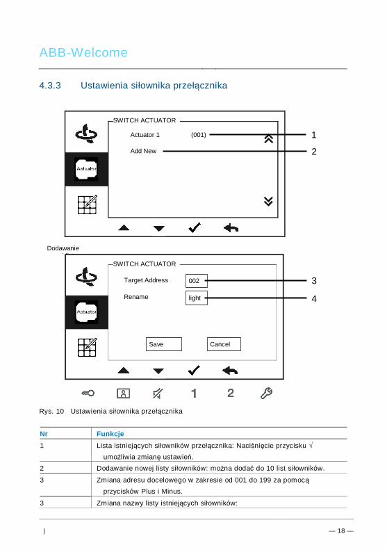
ABB-Welcome
| — 18 —
4.3.3 Ustawienia siłownika przełącznika
Rys. 10 Ustawienia siłownika przełącznika
Nr Funkcje1 Lista istniejących siłowników przełącznika: Naciśnięcie przycisku √
umożliwia zmianę ustawień.2 Dodawanie nowej listy siłowników: można dodać do 10 list siłowników.
3 Zmiana adresu docelowego w zakresie od 001 do 199 za pomocąprzycisków Plus i Minus.
3 Zmiana nazwy listy istniejących siłowników:
3
4
SWITCH ACTUATOR
Actuator 1 (001)
Add New
Target Address
Rename
002
light
Save Cancel
SWITCH ACTUATOR
2
1
Dodawanienowej listy

ABB-Welcome
| — 19 —
Przewijać kolejno litery alfabetu lub cyfry za pomocą przycisków Plus i Minus.
4.3.4 Ustawienia przycisku programowalnego
Rys. 11 Ustawienia przycisku programu
Nr Funkcje1 Ustawianie funkcji przycisku programowalnego, np. odblokowanie drugiego
zamka, połączenie z konsoląportierską, połączenie przez interkom, w łączanie siłownika przełącznika.*Pozycja 2nd-lock (drugi zamek) oznacza, że zamek jest połączony ze
stacją zewnętrzną (NC-NO-COM).*Tylko istniejąca lista połączeń przez interkom lub lista siłownika
przełącznika może zostać przypisanado przycisku programowalnego.
Button 1 Release 2nd-Lock
PROGRAM BUTTON
Button 2 None
1

ABB-Welcome
| — 20 —
4.3.5 Ustawianie przekierowania połączeń
Rys. 12 Ustawianie przekierowania połączeń
Nr Funkcje1 Włączanie/wyłączanie funkcji przekierowania połączeń.
2 Umożliwia wybranie typu połączenia, np. połączenie wewnętrzne lubpołączenie z konsolą portierską.
3 Umożliwia zmianę adresu docelowego, jeżeli wybrano połączenie ze stacjąwewnętrzną.
*W łączenie funkcji przekierowania połączeń powoduje wyłączenie funkcji automatycznegozwalniania blokady.*Tę funkcję można ustawić jedynie w nadrzędnej stacji wewnętrznej*Funkcja jest dostępna w modelu M22302-. /M22303-., kolorowa stacja wewnętrzna wideo zesłuchawką.
1
2
Call Forward
Call Type
√
Indoor
Save Cancel
CALL FORWARD
Target Address 001 31

ABB-Welcome
| — 21 —
4.3.6 Ustawienia automatycznego zwalniania blokady
Rys. 13 Ustawienia automatycznego zwalniania blokady
Nr Funkcje1 Włączanie/wyłączanie funkcji automatycznego zwalniania blokady.
2 Włączanie/wyłączanie funkcji automatycznego zwalniania blokady na okresTime 1 (Czas 1).
3 Ustawianie czasu początkowego i końcowego dla Time 1 (Czas 1)
4 Włączanie/wyłączanie funkcję automatycznego zwalniania blokady naokres Time 2 (Czas 2).
5 Ustawianie czasu początkowego i końcowego dla Time 2 (Czas 2).*Jeśli funkcja automatycznego zwalniania blokady zostanie włączona bez ustawienia jej czasudziałania, funkcja ta będzie aktywna przez 10 godzin.*W łączenie funkcji automatycznego zwalniania blokady powoduje wyłączenie funkcjiprzekierowania połączeń.*Tę funkcję można ustawić jedynie w nadrzędnej stacji wewnętrznej.
1Auto Unlock
Time 1
2
AUTO UNLOCK
√
√
08 00
17 00
:
:
Time 2 X
00 00
00 00
:
:
4
35
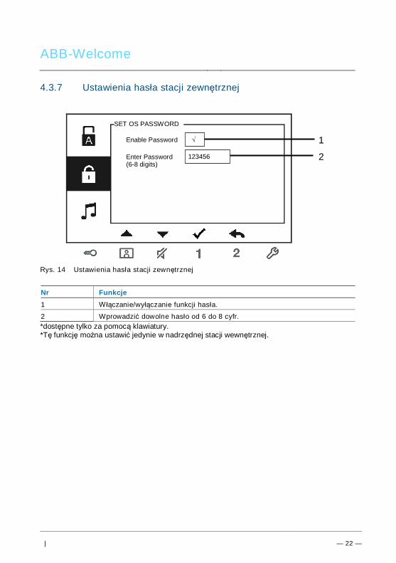
ABB-Welcome
| — 22 —
4.3.7 Ustawienia hasła stacji zewnętrznej
Rys. 14 Ustawienia hasła stacji zewnętrznej
Nr Funkcje1 Włączanie/wyłączanie funkcji hasła.
2 Wprowadzić dowolne hasło od 6 do 8 cyfr.*dostępne tylko za pomocą klawiatury.*Tę funkcję można ustawić jedynie w nadrzędnej stacji wewnętrznej.
1Enable Password
Enter Password(6-8 digits)
SET OS PASSWORD
√
123456 2

ABB-Welcome
| — 23 —
4.3.8 Ustawienia dzwonka
Rys. 15 Dzwonek
Nr Funkcje1 Wybieranie dźwięku dzwonka dla domyślnej stacji zewnętrznej.
2 Wybieranie dźwięku dzwonka dla innej stacji zewnętrznej.
3 Wybieranie dźwięku dzwonka do drzwi mieszkania.
4 Wybieranie dźwięku dzwonka dla pozostałych połączeń, np. z konsoliportierskiej lub
połączeń przez interkom z innych mieszkań.
1Default Outdoor
Other Outdoors
RING TONE
Ring Tone 1
Ring Tone 2 2
Doorbell Ring Tone 3
Others Ring Tone 4
3
4

ABB-Welcome
| — 24 —
4.3.9 Ustawienia głośności
Rys. 16 Ustawianie głośności
Nr Funkcje1 Ustawianie głośności dźwięku dzwonka.
2 – W łączanie/wyłączanie sygnału zwrotnego naciskanegoprzycisku.
1Ringtone Volume
Touchbutton Tone
VOLUME
Volume 3
2√

ABB-Welcome
| — 25 —
4.3.10 Ustawienia daty i godziny
Rys. 17 Ustawienia daty i godziny
Nr Funkcje1 Ustawianie daty.
2 Ustawianie godziny.
3 Włączanie/wyłączanie funkcji czasu letniego.*Funkcja jest dostępna w modelu M22302-. /M22303-., kolorowa stacja wewnętrzna wideo zesłuchawką.
1Date(YYYY-MM-DD)
Time
DATE AND TIME
2013
208
Summer Time √
: 00
- 01 - 01
3

ABB-Welcome
| — 26 —
4.3.11 Ustawienia systemu domofonowego
Rys. 18 Ustawienia systemu domofonowego
Nr Funkcje1 Włączanie/wyłączanie funkcji automatycznego pełnego ekranu.
2 Włączanie/wyłączanie funkcji automatycznej migawki.*Funkcja jest dostępna w modelu M22302-. /M22303-., kolorowa stacja
wewnętrzna wideo ze słuchawką.
3 Włączanie/wyłączanie funkcji kontroli stanu drzwi (dostępne wyłączniepo zainstalowaniu czujnika w stacji wewnętrznej; dioda miga, jeślidrzwi są otwarte).
4 Włączanie/wyłączanie funkcji połączeń nieodebranych (dioda miga, jeślizostało zarejestrowane połączenie
nieodebrane).*Funkcja jest dostępna w modelu M22302-. /M22303-., kolorowa stacja
wewnętrzna wideo ze słuchawką.
1Auto Full Screen
Auto-snapshots
DOOR ENTRY SYSTEM
2
Door Status Check
√
3
Missed
√
√
√ 4
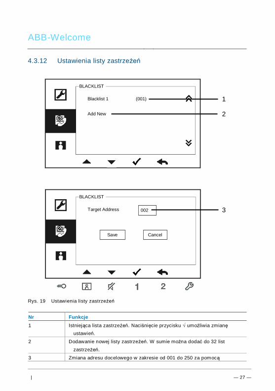
ABB-Welcome
| — 27 —
4.3.12 Ustawienia listy zastrzeżeń
Rys. 19 Ustawienia listy zastrzeżeń
Nr Funkcje1 Istniejąca lista zastrzeżeń. Naciśnięcie przycisku √ umożliwia zmianę
ustawień.
2 Dodawanie nowej listy zastrzeżeń. W sumie można dodać do 32 listzastrzeżeń.
3 Zmiana adresu docelowego w zakresie od 001 do 250 za pomocą
Blacklist 1
Add New
BLACKLIST
(001)
Target Address
BLACKLIST
Save Cancel
002
1
2
3
ABB-Welcome
| — 28 —
przycisków Plus i Minus.*Tę funkcję można ustawić jedynie w nadrzędnej stacji wewnętrznej.*Funkcja jest dostępna w modelu M22302-. /M22303-., kolorowa stacja wewnętrzna wideo zesłuchawką.

ABB-Welcome
| — 29 —
4.3.13 Przeglądanie historii
Rys. 20 Przeglądanie historii
Nr Funkcje1 Menu History (Historia) umożliwia zapisanie do 100 zdarzeń.
– Ikona się wyświetla, jeśli funkcja migawki jest włączona. Ikona się niewyświetla, jeśli funkcja ta jest wyłączona.
– Data, czas i rodzaj zdarzenia zapisywane są razem z migawką.– Kierunki: oznacza połączenia wychodzące
oznacza połączenia odebrane oznacza połączenia nieodebrane
●
HISTORY
1/2Outdoor -1
1/632013-03-2116:45
Outdoor - 1
● 2013-03-2116:45
Outdoor - 1
● 2013-03-2114:24
Outdoor - 1
1
2
3

ABB-Welcome
| — 30 —
2 Naciśnięcie tego przycisku umożliwia przeglądanie szczegółów zdarzenia.Po naciśnięciu dzwonka zawsze wykonywane są dwa zdjęcia
odwiedzającego.
3 Naciśnięcie tego przycisku powoduje usunięcie wpisu.*Funkcja jest dostępna w modelu M22302-. /M22303-., kolorowa stacja wewnętrzna wideo zesłuchawką.

ABB-Welcome
| — 31 —
4.3.14 Ustawienia języka
Rys. 21 Ustawienia języka
4.3.15 Informacje
Rys. 22 Informacje o stacji wewnętrznej (zeskanować kod QR, aby uzyskać szczegółowąinstrukcję stacji wewnętrznej)
English
LANGUAGE
Française
Italiano
Português
Español
Flash Version: V0.11_130723
INFORMATION
MCU Version: V0.11_130722
M/S: Master
Default Outdoor: 1
Indoor St. Add.: 001

ABB-Welcome
| — 32 —
4.3.16 Resetowanie do ustawień fabrycznych
Rys. 23 Resetowanie do ustawień fabrycznych
Nr Funkcje1 Resetowanie wszystkich ustawień:
Resetowanie wszystkich urządzeń i przywracanie wszystkich domyślnychustawień. Operacja ta
nie usuwa zaprogramowanych danych ani historii, np. list interkomówi list siłowników przełącznika.
2 Czyszczenie wszystkich danych:Czyszczenie wszystkich zaprogramowanych danych i historii. Zostaną
również przywróconewszystkie ustawienia fabryczne.
RESET FACTORY DEFAULT
Are you sure to reset?
Cancel OK
Reset All Settings
Clear All Data ×
√

ABB-Welcome
| — 33 —
Pos: 67 /Di nA4 - A nleitu ngen Onlin e/Ueb ersc hrift en/2 ./Reini gung @ 1 9\m od_ 131 0733 980 533 _15. docx @ 10 785 3 @ 2 @ 1
4.4 CzyszczeniePos: 68 /Di nA4 - A nleitu ngen Onlin e/In halt/KNX/Do orEnt ry/Reini gun g/Reini gun g Touchsc ree nm onito r @ 19\m od_ 131 073 410 897 8_15 .docx @ 1 078 62 @ @ 1
OstrzeżenieRyzyko uszkodzenia powierzchni ekranu.Powierzchnię ekranu można uszkodzić twardymi lub ciężkimiprzedmiotami!Nigdy nie należy stosować takich przedmiotów do obsługi ekranudotykowego.– Należy używać palca lub plastikowego rysika.
Powierzchnię ekranu można uszkodzić, stosując płyny do czyszczenialub środki ścierne!– Powierzchnie należy czyścić, używając miękkiej ściereczki lub
dostępnego w sprzedaży płynu do mycia okien.– Nigdy nie należy stosować środków czystości ze środkiem
ściernym.
Pos: 69 /B usch-J aeg er (Neus truk tur )/M odul -Strukt ur/O nline -Doku me ntatio n/Steu er mod ule - Onlin e-Dok ume ntati on ( -- > Für alle Dok ume nte <- -)/ +++ ++ ++ +++ ++ S eiten umb ruch + +++ ++ ++ +++ + @ 9\m od_ 126 8898 668 093 _0. docx @ 521 49 @ @ 1
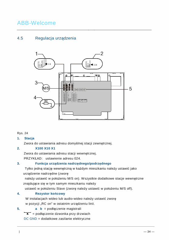
ABB-Welcome
| — 34 —
Pos: 70 /Di nA4 - A nleitu ngen Onlin e/Ueb ersc hrift en/2 ./Ge raet eeins tellun gen @ 1 8\mo d_1 302 768 847 744 _15. docx @ 10 354 8 @ 2 @ 1
4.5 Regulacja urządzeniaPos: 71 /Di nA4 - A nleitu ngen Onlin e/Ueb ersc hrift en/3 ./Abschl usswide rsta nd @ 19\ mod _13 219 5807 990 6_1 5.do cx @ 1100 83 @ 3 @ 1
Pos: 72 /Di nA4 - A nleitu ngen Onlin e/In halt/KNX/Do orEnt ry/Bedie nun g/Abschl usswide rsta nd s etzen 83 220 -AP-xxx @ 19\ mod _13 1072 339 236 9_1 5.do cx @ 1 078 41 @ @ 1
Rys. 24Pos: 74 /Di nA4 - A nleitu ngen Onlin e/In halt/KNX/Do orEnt ry/Bedie nun g/M aste r/Slave Sc halte r setz en 832 20-AP-xxx @ 1 9\m od_1 310 723 320 966 _15. docx @ 10 783 3 @ @
1. StacjaZwora do ustawiania adresu domyślnej stacji zewnętrznej.
2. X100 X10 X1Zwora do ustawiania adresu stacji wewnętrznej.PRZYKŁAD: ustawienie adresu 024.
3. Funkcja urządzenia nadrzędnego/podrzędnegoTylko jedną stację wewnętrzną w każdym mieszkaniu należy ustawić jako
urządzenie nadrzędne (zworęnależy ustawić w położeniu M/S on). Wszystkie dodatkowe stacje wewnętrzne
znajdujące się w tym samym mieszkaniu należyustawić w położeniu Slave (zworę należy ustawić w położeniu M/S off).
4. Rezystor końcowyW instalacjach wideo lub audio-wideo należy ustawić zworęw pozycji „RC on” w ostatnim urządzeniu linii.
5. a b = podłączenie magistrali= podłączenie dzwonka przy drzwiach
DC GND = dodatkowe zasilanie elektrycznePos: 75 /B usch-J aeg er (Neus truk tur )/M odul -Strukt ur/O nline -Doku me ntatio n/Steu er mod ule - Onlin e-Dok ume ntati on ( -- > Für alle Dok ume nte <- -)/ +++ ++ ++ +++ ++ S eiten umb ruch + +++ ++ ++ +++ + @ 9\m od_ 126 8898 668 093 _0. docx @ 521 49 @ @ 1
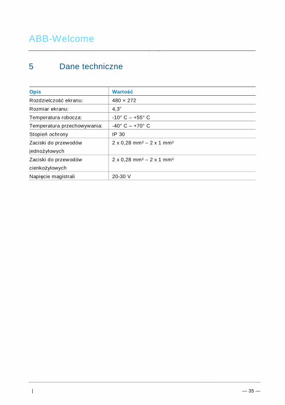
ABB-Welcome
| — 35 —
Pos: 76 /Di nA4 - A nleitu ngen Onlin e/Ueb ersc hrift en/1 ./Technisc he D aten @ 18 \mo d_1 302 615 863 001 _15. docx @ 10 341 6 @ 1 @ 1
5 Dane technicznePos: 77 /Di nA4 - A nleitu ngen Onlin e/In halt/KNX/Do orEnt ry/83 220 -AP-xxx/ Tech nische Date n - 832 20-AP-x xx @ 1 8\m od_ 130 321 285 4559 _15 .docx @ 1 037 05 @ @ 1
Opis WartośćRozdzielczość ekranu: 480 × 272
Rozmiar ekranu: 4,3”
Temperatura robocza: -10° C – +55° CTemperatura przechowywania: -40° C – +70° C
Stopień ochrony IP 30
Zaciski do przewodówjednożyłowych
2 x 0,28 mm² – 2 x 1 mm²
Zaciski do przewodówcienkożyłowych
2 x 0,28 mm² – 2 x 1 mm²
Napięcie magistrali 20-30 V
Pos: 78 /B usch-J aeg er (Neus truk tur )/M odul -Strukt ur/O nline -Doku me ntatio n/Steu er mod ule - Onlin e-Dok ume ntati on ( -- > Für alle Dok ume nte <- -)/ +++ ++ ++ +++ ++ S eiten umb ruch + +++ ++ ++ +++ + @ 9\m od_ 126 8898 668 093 _0. docx @ 521 49 @ @ 1
ABB-Welcome
| — 36 —
Pos: 79 /B usch-J aeg er (Neus truk tur )/M odul -Strukt ur/O nline -Doku me ntatio n/Übe rsch rifte n ( --> Fü r alle Doku men te < -- )/1. E bene /M - O/ Mont age / Ins tallatio n @ 18\ mod _13 0261 396 611 1_1 5.do cx @ 1 033 73 @ 1 @ 1
6 Montaż / instalacjaPos: 80 /B usch-J aeg er (Neus truk tur )/M odul -Strukt ur/O nline -Doku me ntatio n/Siche rheit (- -> Fü r alle D oku ment e < --) /War nhinweis e/Siche rheit - Nie ders pan nun gs- und 230 V-Leit ung en @ 18\ mod _13 026 178 214 91_1 5.d ocx @ 103 465 @ @ 1
OstrzeżenieNapięcie elektryczne!Ryzyko śmierci i pożaru z powodu napięcia elektrycznego równego100–240 V.– Przewodów niskonapięciowych i 100–240 V nie wolno układać
razem w jednej puszce podtynkowej!Jeśli dojdzie do zwarcia, istnieje niebezpieczeństwo wystąpienianapięcia 100–240 V w przewodach niskonapięciowych.
Pos: 81 /B usch-J aeg er (Neus truk tur )/M odul -Strukt ur/O nline -Doku me ntatio n/Siche rheit (- -> Fü r alle D oku ment e < --) /War nhinweis e/Siche rheit - Fachk enn tnisse @ 18 \mo d_1 302 774 384 017_ 15. docx @ 10 356 4 @ 2 @ 1
6.1 Wymagania wobec elektryków
OstrzeżenieNapięcie elektryczne!Urządzenie wolno instalować jedynie osobom posiadającym koniecznąwiedzę i doświadczenie w dziedzinie elektrotechniki.• Niefachowa instalacja zagraża życiu instalatora i użytkowników
instalacji elektrycznej.• Niefachowa instalacja może prowadzić do poważnych szkód
rzeczowych, na przykład pożaru.Wymagana wiedza fachowa i warunki instalacji:• Stosować poniższe zasady bezpieczeństwa (DIN VDE 0105, EN
50110):1. Odłączyć od sieci.2. Zabezpieczyć przed ponownym włączeniem.3. Sprawdzić, czy urządzenie nie jest pod napięciem.4. Podłączyć do uziemienia.5. Zakryć lub odgrodzić sąsiadujące części znajdujące się podnapięciem.
• Stosować odpowiednią odzież ochronną.• Stosować wyłącznie odpowiednie narzędzia i przyrządy pomiarowe.• Sprawdzić rodzaj sieci zasilającej (system TN, system IT i system
TT) i przestrzegać wynikających z tego warunków przyłączenia

ABB-Welcome
| — 37 —
(klasyczne zerowanie, uziemienie ochronne, koniecznośćwykonania dodatkowych pomiarów, itd.).
Pos: 82 /Di nA4 - A nleitu ngen Onlin e/In halt/KNX/Do orEnt ry/M onta ge/ Mont age hinweis e - Allg emei n @ 1 9\m od_ 131 056 367 047 8_15 .docx @ 1 077 43 @ 2 @ 1
6.2 Ogólna instrukcja montażu• Wszystkie odgałęzienia przewodów powinny zostać zakończone podłączonym
urządzeniem magistrali (np. stacja wewnętrzna, zewnętrzna lub urządzeniesystemowe).
• Nie instalować centrali systemu bezpośrednio obok transformatorów dzwonka lubinnych urządzeń zasilających (unikanie interferencji).
• Nie układać przewodów magistrali systemowej wspólnie z przewodami 100–240 V.• Nie używać wspólnego kabla dla przewodów przyłączowych elektrozaczepów i
przewodów magistrali systemowej.• Unikać złączeń między różnymi typami kabli.• W kablu, który ma cztery lub więcej żył, do magistrali systemowej należy
wykorzystać tylko dwie żyły.• Przy łączeniu przelotowym nigdy nie prowadzić przychodzącej i wychodzącej
magistrali w tym samym kablu.• Nigdy nie prowadzić magistrali wewnętrznej i zewnętrznej w tym samym kablu.Pos: 83 /B usch-J aeg er (Neus truk tur )/M odul -Strukt ur/O nline -Doku me ntatio n/Steu er mod ule - Onlin e-Dok ume ntati on ( -- > Für alle Dok ume nte <- -)/ +++ ++ ++ +++ ++ S eiten umb ruch + +++ ++ ++ +++ + @ 9\m od_ 126 8898 668 093 _0. docx @ 521 49 @ @ 1
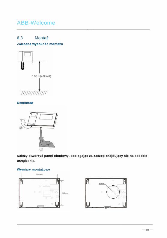
ABB-Welcome
| — 38 —
Pos: 84 /B usch-J aeg er (Neus truk tur )/M odul -Strukt ur/O nline -Doku me ntatio n/Übe rsch rifte n ( --> Fü r alle Doku men te < -- )/2. E bene /M - O/ Mont age @ 1 8\m od_1 302 615 960 458 _15. docx @ 10 342 4 @ 2 @ 1
6.3 MontażPos: 85. 1 /DinA4 - Anleit ung en O nline/I nhal t/KNX/DoorE ntry/ 832 20-AP-xxx /Mo nta ge - Mo dule/ Mon tag e - Mon tage dos e -- 83 220 -AP-xxx @ 19\ mod _132 325 040 684 8_1 5.doc x @ 1 110 98 @ @ 1
Zalecana wysokość montażu
Demontaż
Należy otworzyć panel obudowy, pociągając za zaczep znajdujący się na spodzieurządzenia.
Wymiary montażowe

ABB-Welcome
| — 39 —
1. Na spodzie obudowy znajdują się otwory na śruby do montażu urządzenia naścianie zgodnie z powyższymi wymiarami montażowymi.
2. Ponadto spód urządzenia można przymocować do istniejącej skrzynki podtynkowej.Na powyższych rysunkach zostały przedstawione wymiary kompatybilnej skrzynkipodtynkowej.
Okablowanie
Należy przymocować spód urządzenia i podłącz je zgodnie z instrukcją przedstawionąna rysunkach. Izolowana część końcówki przewodu nie może być dłuższa niż 10 mm.
UstawieniaUstawienia adresów preferowanych stacji zewnętrznych i adresów stacji wewnętrznychna zworze (patrz rozdział Regulacja urządzenia).

ABB-Welcome
| — 40 —
Montaż na ścianie
1. Należy przymocować spód urządzenia do ściany.2. Mocowanie na zatrzaski górnej i dolnej części urządzenia: należy umieścić górną
część urządzenia na wypustkach zatrzasków, a następnie docisnąć dolną stroną dospodu urządzenia do momentu zablokowania zatrzasków.
Montaż na skrzynce podtynkowej
1. Należy przymocować spód urządzenia do istniejącej skrzynki podtynkowej.2. Mocowanie na zatrzaski górnej i dolnej części urządzenia: należy umieścić górną
część urządzenia na wypustkach zatrzasków, a następnie docisnąć dolną stroną dospodu urządzenia do momentu zablokowania zatrzasków.

ABB-Welcome
| — 41 —
Montaż na podstawce na biurko
1. Należy zamocować dolną część urządzenia na podstawce na biurko.2. Mocowanie na zatrzaski górnej i dolnej części urządzenia: należy umieścić górną
część urządzenia na wypustkach zatrzasków, a następnie docisnąć dolną stroną dospodu urządzenia do momentu zablokowania zatrzasków.
Zakończono instalację wewnętrznej stacji.
Pos: 94 /B usch-J aeg er (Neus truk tur )/M odul -Strukt ur/O nline -Doku me ntatio n/Steu er mod ule - Onlin e-Dok ume ntati on ( -- > Für alle Dok ume nte <- -)/ +++ ++ ++ +++ ++ S eiten umb ruch + +++ ++ ++ +++ + @ 9\m od_ 126 8898 668 093 _0. docx @ 521 49 @ @ 1

ABB-Welcome M Error! Use the Home tab
to apply 标题 1 to the
text that you want to
appear here.
| — 42 —
Pos: 95 /Di nA4 - A nleitu ngen Onlin e/In halt/KNX/Do orEnt ry/Proj ektier ung -M erkbl att/Pr ojektie rPos: 9 7 /Busc h-Ja ege r (N eust ruktu r)/ Mo dul-Str uktu r/Onli ne-D oku ment ation /Rückseit en (-- > Für alle Dok um ente <- -)/R ückseit e - Bus ch-J aeg er - Allgem ein @ 20\ mod _13 273 200 748 86_1 5.d ocx @ 137 103 @ @ 1
Uwaga=== E nde der Liste für Tex tma rke Ba ckcove r = ==
Firma ABB zastrzega sobie prawo do wprowadzania zmian technicznych, jak równieżzmian treści niniejszego dokumentu w dowolnym momencie i bez uprzedzenia.Szczegółowe dane techniczne uzgodnione w czasie składania zamówienia stosuje siędo wszystkich zamówień. Firma ABB nie ponosi żadnej odpowiedzialności za błędy aniza braki, jakie mogą pojawić się w niniejszym dokumencie. Wszelkie prawa do niniejszego dokumentu i zawartych w nim informacji są zastrzeżone.Osobom trzecim zabrania się powielania, przesyłania czy ponownego wykorzystywanianiniejszego dokumentu lub jego części bez uprzedniej pisemnej zgody firmy ABB.