Embed Size (px)
Citation preview
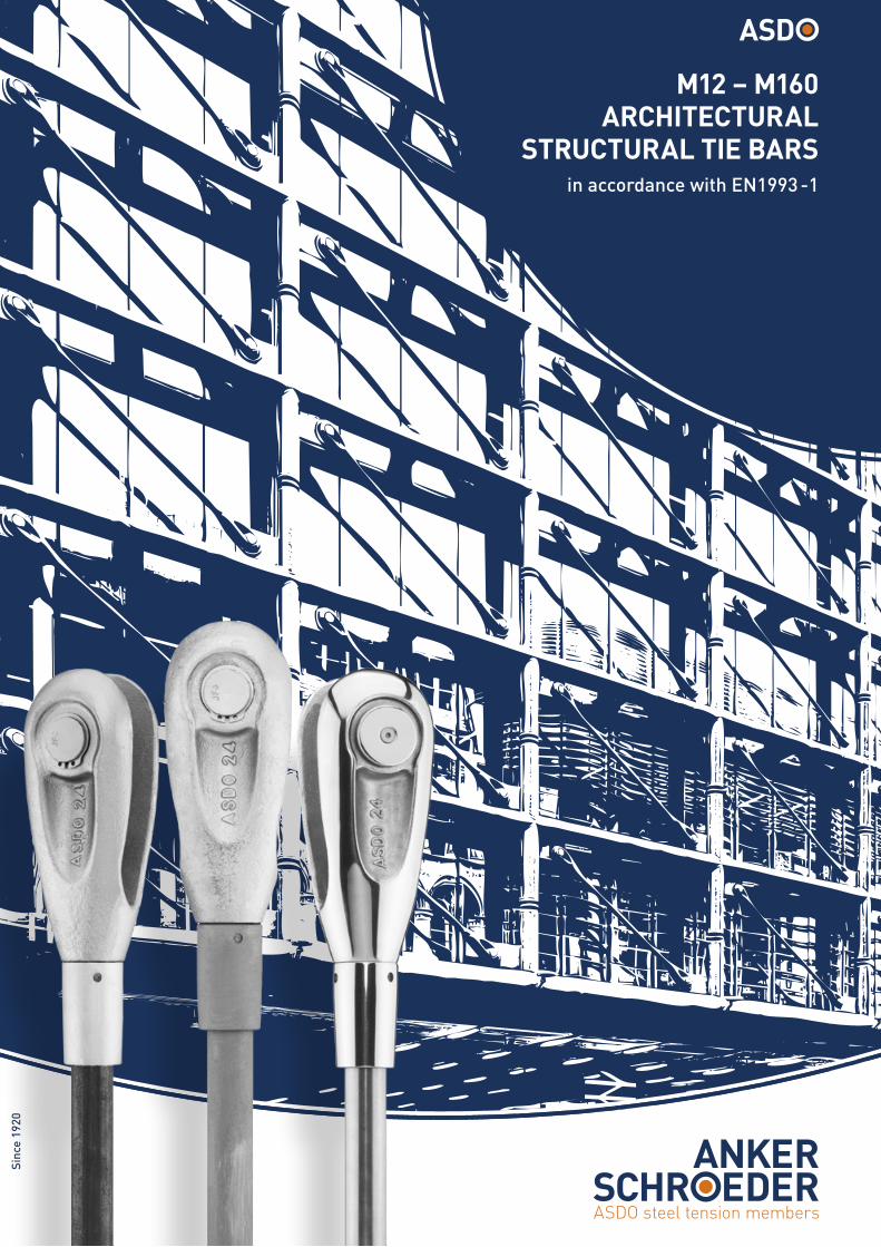
M12 – M160ARCHITECTURAL
STRUCTURAL TIE BARSin accordance with EN1993 -1
Sinc
e 19
20
32
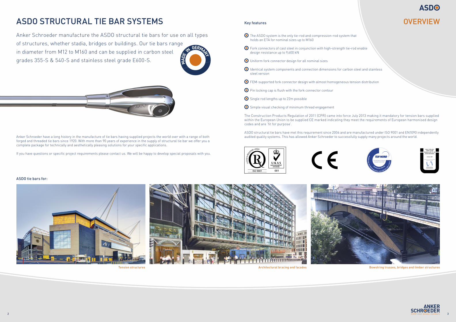
Anker Schroeder manufacture the ASDO structural tie bars for use on all types
of structures, whether stadia, bridges or buildings. Our tie bars range
in diameter from M12 to M160 and can be supplied in carbon steel
grades 355-S & 540-S and stainless steel grade E600-S.
The Construction Products Regulation of 2011 (CPR) came into force July 2013 making it mandatory for tension bars supplied within the European Union to be supplied CE marked indicating they meet the requirements of European harmonised design codes and are ‘fit for purpose’.
ASDO structural tie bars have met this requirement since 2004 and are manufactured under ISO 9001 and EN1090 independently audited quality systems. This has allowed Anker Schroeder to successfully supply many projects around the world.
The ASDO system is the only tie-rod and compression-rod system that holds an ETA for nominal sizes up to M160
Fork connectors of cast steel in conjunction with high-strength tie-rod enable design resistance up to 9,600 kN
Uniform fork connector design for all nominal sizes
Identical system components and connection dimensions for carbon steel and stainless steel version
FEM-supported fork connector design with almost homogeneous tension distribution
Pin locking cap is flush with the fork connector contour
Single rod lengths up to 22m possible
Simple visual checking of minimum thread engagement
ASDO STRUCTURAL TIE BAR SYSTEMS
Tension structures
ASDO tie bars for:
Bowstring trusses, bridges and timber structures
OVERVIEW
ISO 9001
Architectural bracing and facades
Anker Schroeder have a long history in the manufacture of tie bars having supplied projects the world over with a range of both forged and threaded tie bars since 1920. With more than 90 years of experience in the supply of structural tie bar we offer you a complete package for technically and aesthetically pleasing solutions for your specific applications. If you have questions or specific project requirements please contact us. We will be happy to develop special proposals with you.
Key features
54
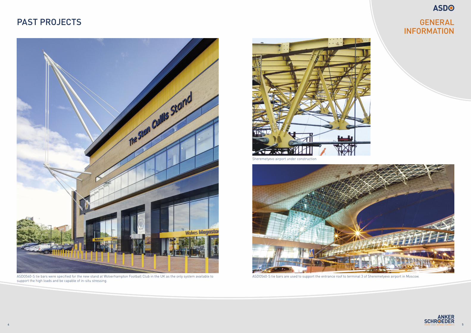
PAST PROJECTS
ASDO540-S tie bars are used to support the entrance roof to terminal 3 of Sheremetyevo airport in Moscow.
Sheremetyevo airport under construction
ASDO540-S tie bars were specified for the new stand at Wolverhampton Football Club in the UK as the only system available to support the high loads and be capable of in-situ stressing.
GENERAL INFORMATION
76
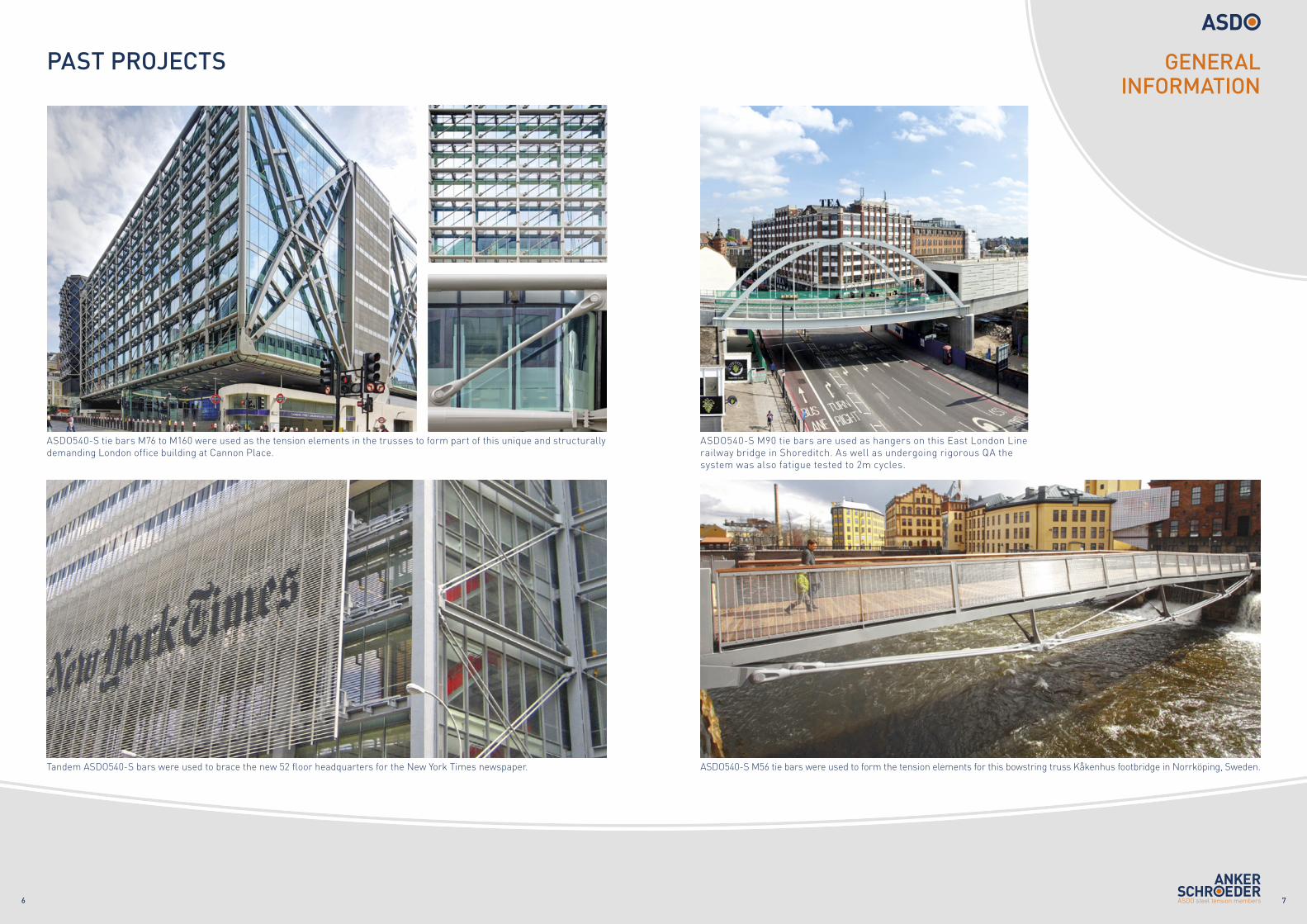
PAST PROJECTS
ASDO540-S tie bars M76 to M160 were used as the tension elements in the trusses to form part of this unique and structurally demanding London office building at Cannon Place.
Tandem ASDO540-S bars were used to brace the new 52 floor headquarters for the New York Times newspaper. ASDO540-S M56 tie bars were used to form the tension elements for this bowstring truss Kåkenhus footbridge in Norrköping, Sweden.
ASDO540-S M90 tie bars are used as hangers on this East London Linerailway bridge in Shoreditch. As well as undergoing rigorous QA thesystem was also fatigue tested to 2m cycles.
GENERAL INFORMATION
98
Table 3 - Carbon steel
Dim
ensi
onal
dat
a Nominal thread size M12 M16 M20 M24 M27 M30 M36 M42 M45 M48 M52 M56 M60 M64 M68 M72 M76 M80 M85 M90 M95 M100 M105 M110 M115 M120 M130 M140 M150 M160Nominal shaft size mm 12 16 20 24 27 30 36 42 45 48 52 56 60 64 68 72 76 80 85 90 95 100 105 110 115 120 130 140 150 160Shaft area, Ag mm2 113 201 314 452 573 707 1,018 1,385 1,590 1,810 2,124 2,463 2,827 3,217 3,632 4,072 4,536 5,027 5,675 6,362 7,088 7,854 8,659 9,503 10,387 11,310 13,273 15,394 17,671 20,106Thread pitch mm 1.75 2 2.5 3 3 3.5 4 4.5 4.5 5 5 5.5 5.5 6 6 6 6 6 6 6 6 6 6 6 6 6 6 6 6 6Thread stress area, As mm2 84 157 245 353 459 561 817 1,121 1,306 1,473 1,758 2,030 2,362 2,676 3,055 3,460 3,889 4,344 4,948 5,591 6,273 6,995 7,755 8,556 9,395 10,274 12,149 14,181 16,370 18,716Weight per metre (bar) kg/m 0.9 1.6 2.5 3.6 4.5 5.5 8.0 10.9 12.5 14.2 16.7 19.3 22.2 25.3 28.5 32.0 35.6 39.5 44.5 49.9 55.6 61.7 68.0 74.6 81.5 88.8 104.2 120.8 138.7 157.8
Load
ca
paci
ties ASDO350-S
Yield kN - - - - - - - - - - - - - - - - - - - - - 2,483 2,753 3,037 3,335 3,647 4,313 4,183 4,829 5,334Ultimate kN - - - - - - - - - - - - - - - - - - - - - 3,567 3,955 4,363 4,791 5,240 6,196 6,665 7,694 8,422
ASDO540-SYield kN 30 85 132 190 248 303 441 605 705 795 949 1,096 1,275 1,445 1,650 1,868 2,100 2,346 2,672 2,907 3,262 3,637 4,886 5,390 5,919 6,472 7,654 8,934 10,313 11,791
Ultimate kN 43 110 171 247 322 392 572 785 914 1,031 1,230 1,421 1,653 1,873 2,139 2,422 2,723 3,041 3,463 3,914 4,391 4,896 5,506 6,074 6,670 7,294 8,626 10,068 11,623 13,289
Des
ign
resi
stan
ce1
ASDO350-S Ft,Rd kN - - - - - - - - - - - - - - - - - - - - - 2,535 2,795 3,067 3,352 3,650 4,284 4,128 4,739 5,209
ASDO540-S Ft,Rd kN 31 79 123 178 232 283 412 565 658 742 886 1,023 1,190 1,349 1,540 1,744 1,960 2,189 2,494 2,818 3,162 3,525 3,965 4,374 4,803 5,252 6,210 7,249 8,368 9,568
Table 4 - Stainless steel
Dim
ensi
onal
dat
a Nominal thread size M12 M16 M20 M24 M27 M30 M36 M42 M48 M56Nominal shaft size mm 10.8 15 18 22 25 28 34 39 45 52Shaft area, Ag mm2 92 177 254 380 491 616 908 1,195 1,590 2,124Thread pitch mm 1.75 2 2.5 3 3 3.5 4 4.5 5 5.5Thread stress area, As mm2 84 157 245 353 459 561 817 1,121 1,473 2,030Weight per metre (bar) kg/m 0.7 1.4 2.0 3.0 3.9 4.9 7.3 9.6 12.7 17.0
Load
ca
paci
ties
ASDOE600-S
Yield kN 51 94 147 212 276 336 490 673 678 934
Ultimate kN 67 125 196 282 368 448 653 897 958 1,320
Des
ign
resi
stan
ce1
Ft,Rd kN 47 87 136 195 255 311 453 621 656 900
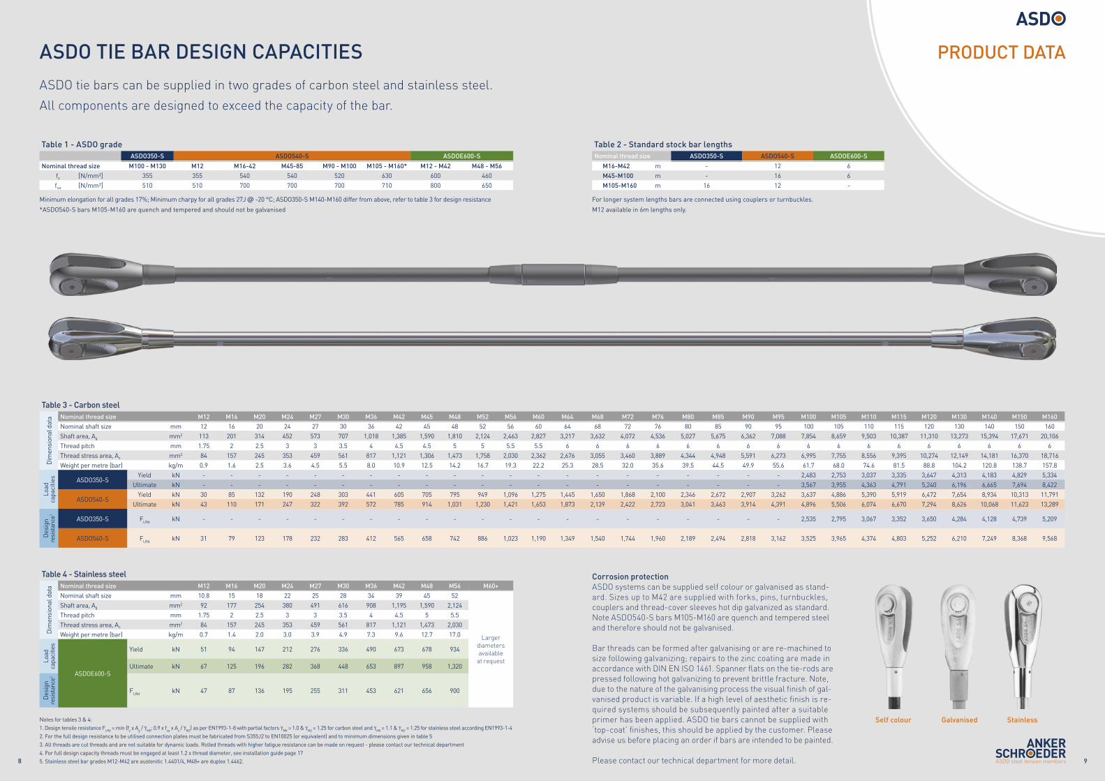
ASDO tie bars can be supplied in two grades of carbon steel and stainless steel.
All components are designed to exceed the capacity of the bar.
Table 1 - ASDO grade ASDO350-S ASDO540-S ASDOE600-S
Nominal thread size M100 - M130 M12 M16-42 M45-85 M90 - M100 M105 - M160* M12 - M42 M48 - M56fy [N/mm²] 355 355 540 540 520 630 600 460fua [N/mm²] 510 510 700 700 700 710 800 650
Minimum elongation for all grades 17%; Minimum charpy for all grades 27J @ -20 °C; ASDO350-S M140-M160 differ from above, refer to table 3 for design resistance
*ASDO540-S bars M105-M160 are quench and tempered and should not be galvanised
Table 2 - Standard stock bar lengthsNominal thread size ASDO350-S ASDO540-S ASDOE600-S
M16-M42 m - 12 6M45-M100 m - 16 6M105-M160 m 16 12 -
For longer system lengths bars are connected using couplers or turnbuckles.
M12 available in 6m lengths only.
Notes for tables 3 & 4: 1. Design tensile resistance Ft,Rd = min {fy x Ag / γM0; 0.9 x fua x As / γM2} as per EN1993-1-8 with partial factors γM0 = 1.0 & γM2 = 1.25 for carbon steel and γM0 = 1.1 & γM2 = 1.25 for stainless steel according EN1993-1-42. For the full design resistance to be utilised connection plates must be fabricated from S355J2 to EN10025 (or equivalent) and to minimum dimensions given in table 53. All threads are cut threads and are not suitable for dynamic loads. Rolled threads with higher fatigue resistance can be made on request - please contact our technical department 4. For full design capacity threads must be engaged at least 1.2 x thread diameter, see installation guide page 175. Stainless steel bar grades M12-M42 are austenitic 1.4401/4, M48+ are duplex 1.4462.
PRODUCT DATAASDO TIE BAR DESIGN CAPACITIES
Corrosion protectionASDO systems can be supplied self colour or galvanised as stand-ard. Sizes up to M42 are supplied with forks, pins, turnbuckles, couplers and thread-cover sleeves hot dip galvanized as standard. Note ASDO540-S bars M105-M160 are quench and tempered steel and therefore should not be galvanised.
Bar threads can be formed after galvanising or are re-machined to size following galvanizing; repairs to the zinc coating are made in accordance with DIN EN ISO 1461. Spanner flats on the tie-rods are pressed following hot galvanizing to prevent brittle fracture. Note, due to the nature of the galvanising process the visual finish of gal-vanised product is variable. If a high level of aesthetic finish is re-quired systems should be subsequently painted after a suitable primer has been applied. ASDO tie bars cannot be supplied with ‘top-coat’ finishes, this should be applied by the customer. Please advise us before placing an order if bars are intended to be painted.
Please contact our technical department for more detail.
Self colour Galvanised Stainless
M60+
Largerdiametersavailable
at request
1110
ASDO DIMENSIONAL DATACAD 2 ( 1 : 3 )
CAD 4 ( 1 : 3 )
CAD 11 ( 1 : 3 )
CAD 13 ( 1 : 3 )
CAD 12 ( 1 : 3 )
CAD 14 ( 1 : 3 )
CAD 8 ( 1 : 4 )
CAD 9 ( 1 : 4 )
CAD 10 ( 1 : 4 )
CAD 36 ( 1 : 4 )
CAD 6 ( 1 : 4 )
CAD 7 ( 1 : 4 )CAD 5 ( 1 : 4 )
CAD 1 ( 1 : 3 )
CAD 3A- A ( 1 : 3 )
CAD 2 ( 1 : 3 )
CAD 4 ( 1 : 3 )
CAD 11 ( 1 : 3 )
CAD 13 ( 1 : 3 )
CAD 12 ( 1 : 3 )
CAD 14 ( 1 : 3 )
CAD 8 ( 1 : 4 )
CAD 9 ( 1 : 4 )
CAD 10 ( 1 : 4 )
CAD 36 ( 1 : 4 )
CAD 6 ( 1 : 4 )
CAD 7 ( 1 : 4 )CAD 5 ( 1 : 4 )
CAD 1 ( 1 : 3 )
CAD 3A- A ( 1 : 3 )
CAD 2 ( 1 : 3 )
CAD 4 ( 1 : 3 )
CAD 11 ( 1 : 3 )
CAD 13 ( 1 : 3 )
CAD 12 ( 1 : 3 )
CAD 14 ( 1 : 3 )
CAD 8 ( 1 : 4 )
CAD 9 ( 1 : 4 )
CAD 10 ( 1 : 4 )
CAD 36 ( 1 : 4 )
CAD 6 ( 1 : 4 )
CAD 7 ( 1 : 4 )CAD 5 ( 1 : 4 )
CAD 1 ( 1 : 3 )
CAD 3A- A ( 1 : 3 )
CAD 2 ( 1 : 3 )
CAD 4 ( 1 : 3 )
CAD 11 ( 1 : 3 )
CAD 13 ( 1 : 3 )
CAD 12 ( 1 : 3 )
CAD 14 ( 1 : 3 )
CAD 8 ( 1 : 4 )
CAD 9 ( 1 : 4 )
CAD 10 ( 1 : 4 )
CAD 36 ( 1 : 4 )
CAD 6 ( 1 : 4 )
CAD 7 ( 1 : 4 )CAD 5 ( 1 : 4 )
CAD 1 ( 1 : 3 )
CAD 3A- A ( 1 : 3 )
CAD 2 ( 1 : 3 )
CAD 4 ( 1 : 3 )
CAD 11 ( 1 : 3 )
CAD 13 ( 1 : 3 )
CAD 12 ( 1 : 3 )
CAD 14 ( 1 : 3 )
CAD 8 ( 1 : 4 )
CAD 9 ( 1 : 4 )
CAD 10 ( 1 : 4 )
CAD 36 ( 1 : 4 )
CAD 6 ( 1 : 4 )
CAD 7 ( 1 : 4 )CAD 5 ( 1 : 4 )
CAD 1 ( 1 : 3 )
CAD 3A- A ( 1 : 3 )
CAD 2 ( 1 : 3 )
CAD 4 ( 1 : 3 )
CAD 11 ( 1 : 3 )
CAD 13 ( 1 : 3 )
CAD 12 ( 1 : 3 )
CAD 14 ( 1 : 3 )
CAD 8 ( 1 : 4 )
CAD 9 ( 1 : 4 )
CAD 10 ( 1 : 4 )
CAD 36 ( 1 : 4 )
CAD 6 ( 1 : 4 )
CAD 7 ( 1 : 4 )CAD 5 ( 1 : 4 )
CAD 1 ( 1 : 3 )
CAD 3A- A ( 1 : 3 )
CAD 2 ( 1 : 3 )
CAD 4 ( 1 : 3 )
CAD 11 ( 1 : 3 )
CAD 13 ( 1 : 3 )
CAD 12 ( 1 : 3 )
CAD 14 ( 1 : 3 )
CAD 8 ( 1 : 4 )
CAD 9 ( 1 : 4 )
CAD 10 ( 1 : 4 )
CAD 36 ( 1 : 4 )
CAD 6 ( 1 : 4 )
CAD 7 ( 1 : 4 )CAD 5 ( 1 : 4 )
CAD 1 ( 1 : 3 )
CAD 3A- A ( 1 : 3 )
CAD 2 ( 1 : 3 )
CAD 4 ( 1 : 3 )
CAD 11 ( 1 : 3 )
CAD 13 ( 1 : 3 )
CAD 12 ( 1 : 3 )
CAD 14 ( 1 : 3 )
CAD 8 ( 1 : 4 )
CAD 9 ( 1 : 4 )
CAD 10 ( 1 : 4 )
CAD 36 ( 1 : 4 )
CAD 6 ( 1 : 4 )
CAD 7 ( 1 : 4 )CAD 5 ( 1 : 4 )
CAD 1 ( 1 : 3 )
CAD 3A- A ( 1 : 3 )
CAD 2 ( 1 : 3 )
CAD 4 ( 1 : 3 )
CAD 11 ( 1 : 3 )
CAD 13 ( 1 : 3 )
CAD 12 ( 1 : 3 )
CAD 14 ( 1 : 3 )
CAD 8 ( 1 : 4 )
CAD 9 ( 1 : 4 )
CAD 10 ( 1 : 4 )
CAD 36 ( 1 : 4 )
CAD 6 ( 1 : 4 )
CAD 7 ( 1 : 4 )CAD 5 ( 1 : 4 )
CAD 1 ( 1 : 3 )
CAD 3A- A ( 1 : 3 )
CAD 2 ( 1 : 3 )
CAD 4 ( 1 : 3 )
CAD 11 ( 1 : 3 )
CAD 13 ( 1 : 3 )
CAD 12 ( 1 : 3 )
CAD 14 ( 1 : 3 )
CAD 8 ( 1 : 4 )
CAD 9 ( 1 : 4 )
CAD 10 ( 1 : 4 )
CAD 36 ( 1 : 4 )
CAD 6 ( 1 : 4 )
CAD 7 ( 1 : 4 )CAD 5 ( 1 : 4 )
CAD 1 ( 1 : 3 )
CAD 3A- A ( 1 : 3 )
CAD 2 ( 1 : 3 )
CAD 4 ( 1 : 3 )
CAD 11 ( 1 : 3 )
CAD 13 ( 1 : 3 )
CAD 12 ( 1 : 3 )
CAD 14 ( 1 : 3 )
CAD 8 ( 1 : 4 )
CAD 9 ( 1 : 4 )
CAD 10 ( 1 : 4 )
CAD 36 ( 1 : 4 )
CAD 6 ( 1 : 4 )
CAD 7 ( 1 : 4 )CAD 5 ( 1 : 4 )
CAD 1 ( 1 : 3 )
CAD 3A- A ( 1 : 3 )
CAD 2 ( 1 : 3 )
CAD 4 ( 1 : 3 )
CAD 11 ( 1 : 3 )
CAD 13 ( 1 : 3 )
CAD 12 ( 1 : 3 )
CAD 14 ( 1 : 3 )
CAD 8 ( 1 : 4 )
CAD 9 ( 1 : 4 )
CAD 10 ( 1 : 4 )
CAD 36 ( 1 : 4 )
CAD 6 ( 1 : 4 )
CAD 7 ( 1 : 4 )CAD 5 ( 1 : 4 )
CAD 1 ( 1 : 3 )
CAD 3A- A ( 1 : 3 )
CAD 2 ( 1 : 3 )
CAD 4 ( 1 : 3 )
CAD 11 ( 1 : 3 )
CAD 13 ( 1 : 3 )
CAD 12 ( 1 : 3 )
CAD 14 ( 1 : 3 )
CAD 8 ( 1 : 4 )
CAD 9 ( 1 : 4 )
CAD 10 ( 1 : 4 )
CAD 36 ( 1 : 4 )
CAD 6 ( 1 : 4 )
CAD 7 ( 1 : 4 )CAD 5 ( 1 : 4 )
CAD 1 ( 1 : 3 )
CAD 3A- A ( 1 : 3 )
CAD 2 ( 1 : 3 )
CAD 4 ( 1 : 3 )
CAD 11 ( 1 : 3 )
CAD 13 ( 1 : 3 )
CAD 12 ( 1 : 3 )
CAD 14 ( 1 : 3 )
CAD 8 ( 1 : 4 )
CAD 9 ( 1 : 4 )
CAD 10 ( 1 : 4 )
CAD 36 ( 1 : 4 )
CAD 6 ( 1 : 4 )
CAD 7 ( 1 : 4 )CAD 5 ( 1 : 4 )
CAD 1 ( 1 : 3 )
CAD 3A- A ( 1 : 3 )
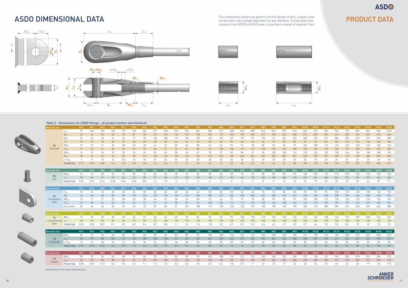
The components shown are generic and the design of pins, couplers and turnbuckles may change dependent on bar diameter. Turnbuckles and couplers from M105 to M160 have a cross bore instead of spanner flats.
Table 5 - Dimensions for ASDO fittings - all grades (carbon and stainless)Nominal size M12 M16 M20 M24 M27 M30 M36 M42 M45 M48 M52 M56 M60 M64 M68 M72 M76 M80 M85 M90 M95 M100 M105 M110 M115 M120 M130 M140 M150 M160
FE Fork end
LFE 77 104 129 155 172 193 232 271 290 310 334 361 386 412 438 463 489 516 547 579 610 645 677 709 742 773 837 901 966 1,031BFE 33 44 53 65 73 81 98 114 122 130 139 150 159 172 182 193 203 219 230 243 258 271 287 301 316 330 354 381 410 436WFE 31 42 50 61 66 77 90 104 108 119 126 139 149 159 167 179 191 196 211 226 237 248 259 271 284 303 327 351 375 405TFE 12 17 18 23 23 28 33 38 38 44 44 49 54 59 59 64 69 74 79 84 89 94 96 101 106 116 126 136 146 156ØDFE 13 17 21 25 28 32 38 44 47 50 54 58 62 66 70 74 78 82 87 92 97 102 108 113 118 123 133 143 153 163L1FE 19 26 31 38 42 47 57 66 71 76 81 88 93 100 106 112 119 128 133 140 150 160 167 175 184 191 207 222 239 255MEFE 14 19 24 29 32 36 43 50 54 58 62 67 72 77 82 86 91 96 102 108 114 120 126 132 138 144 156 168 180 192NFE 38 51 64 76 84 95 114 134 143 152 166 181 196 210 225 240 254 267 287 306 321 340 359 377 395 413 449 486 522 559+/-VFE 6 8 10 12 13,5 15 18 21 23 24 25 25 25 25 25 25 25 25 25 25 25 25 25 25 25 25 25 25 25 25Weight [kg] 0.17 0.42 0.83 1.4 2.0 2.8 4.8 7.6 9.4 11 15 18 22 27 33 39 45 51 63 74 85 100 119 136 156 177 221 277 340 417
Nominal size M12 M16 M20 M24 M27 M30 M36 M42 M45 M48 M52 M56 M60 M64 M68 M72 M76 M80 M85 M90 M95 M100 M105 M110 M115 M120 M130 M140 M150 M160
PN Pin
ØDPN 12 16 20 24 27 30 36 42 45 48 52 56 60 64 68 72 76 80 85 90 95 100 105 110 115 120 130 140 150 160LPN 30 40 47 57 63 73 85 97 102 111 120 129 140 151 157 166 175 182 195 205 218 229 241 250 261 277 301 323 344 365Weight [kg] 0.03 0.07 0.14 0.25 0.34 0.46 0.81 1.2 1.5 2 2 3 4 5 5 6 7 8 11 12 14 16 19 22 25 29 37 46 57 71
Nominal size M12 M16 M20 M24 M27 M30 M36 M42 M45 M48 M52 M56 M60 M64 M68 M72 M76 M80 M85 M90 M95 M100 M105 M110 M115 M120 M130 M140 M150 M160
CP Connection
plate
TCP 10 15 15 20 20 25 30 35 35 40 40 45 50 55 55 60 65 70 75 80 85 90 90 95 100 110 120 130 140 150BCP 42 56 68 80 90 104 122 142 152 160 174 186 200 212 224 238 250 264 280 296 312 328 346 362 378 394 426 458 490 522ØDCP 13 17 21 25 28 32 38 44 47 50 54 58 62 66 70 74 78 82 87 92 97 102 108 113 118 123 133 143 153 163L1CP 21 28 34 40 45 52 61 71 76 80 87 93 100 106 112 119 125 132 140 148 156 164 173 181 189 197 213 229 245 261L2CP (min) 29 36 46 53 57 62 72 81 86 91 101 108 113 120 126 132 139 148 153 160 170 180 192 200 209 216 232 247 264 280
Nominal size M12 M16 M20 M24 M27 M30 M36 M42 M45 M48 M52 M56 M60 M64 M68 M72 M76 M80 M85 M90 M95 M100 M105 M110 M115 M120 M130 M140 M150 M160
TCLocking thread
cover
ØETC 17 23 29 35 39 42 51 60 64 69 75 81 87 92 99 104 110 113 122 129 134 143 152 158 166 173 187 202 216 232LTC 30 40 50 55 60 70 80 95 100 110 115 120 120 135 135 135 135 140 140 140 140 140 140 140 140 140 140 140 140 140Weight [kg] 0.03 0.05 0.09 0.1 0.2 0.3 0.4 0.7 0.8 1.1 1.3 1.6 1.8 2.2 2.7 2.9 3.3 3.6 4.2 4.7 4.9 5.7 6.6 7.0 7.8 8.6 10 12 13 15
Nominal size M12 M16 M20 M24 M27 M30 M36 M42 M45 M48 M52 M56 M60 M64 M68 M72 M76 M80 M85 M90 M95 M100 M105 M110 M115 M120 M130 M140 M150 M160
TBTurnbuckle
ØDTB 20 27 36 42 48 51 60 70 76 83 89 95 102 108 114 121 127 133 140 152 159 171 178 191 194 203 219 241 254 273LTB 53 70 88 106 119 132 158 185 198 211 225 234 244 254 263 273 282 292 304 326 338 350 387 399 411 423 447 471 495 519+/-VTB 12 16 20 24 27 30 36 42 45 48 50 50 50 50 50 50 50 50 50 50 50 50 50 50 50 50 50 50 50 50Weight [kg] 0.09 0.16 0.32 0.6 0.9 1.2 1.8 2.8 3.3 3.9 5.4 6.2 8.5 10 12 14 16 18 20 24 30 34 42 49 62 61 82 96 115 147
Nominal size M12 M16 M20 M24 M27 M30 M36 M42 M45 M48 M52 M56 M60 M64 M68 M72 M76 M80 M85 M90 M95 M100 M105 M110 M115 M120 M130 M140 M150 M160
COCoupler
ØDCO 20 27 36 42 48 51 60 70 76 83 89 95 102 108 114 121 127 133 140 152 159 171 178 191 194 203 219 241 254 273LCO 29 39 48 58 65 72 87 101 108 116 125 135 144 154 164 173 183 192 204 226 238 250 287 299 311 323 347 371 395 419Weight [kg] 0.05 0.09 0.17 0.3 0.5 0.7 1.1 1.7 2.0 2.3 3.2 3.9 5.3 6.3 7.8 9.2 11 12 14 17 22 25 32 37 47 47 65 77 93 119
PRODUCT DATA
All dimensions in mm unless noted otherwise
T CP
BC
P
L2CP
A A
L1CP
ØD
CP
LCO LTB
ØD
CO
ØD
TB
BFE
LFE LTC
ØDFE /ØDPN +/-VFE+/-VFE
L1FE NFE MEFE LTC
T FE
L PN
WFE
ØDTCØETC
1312
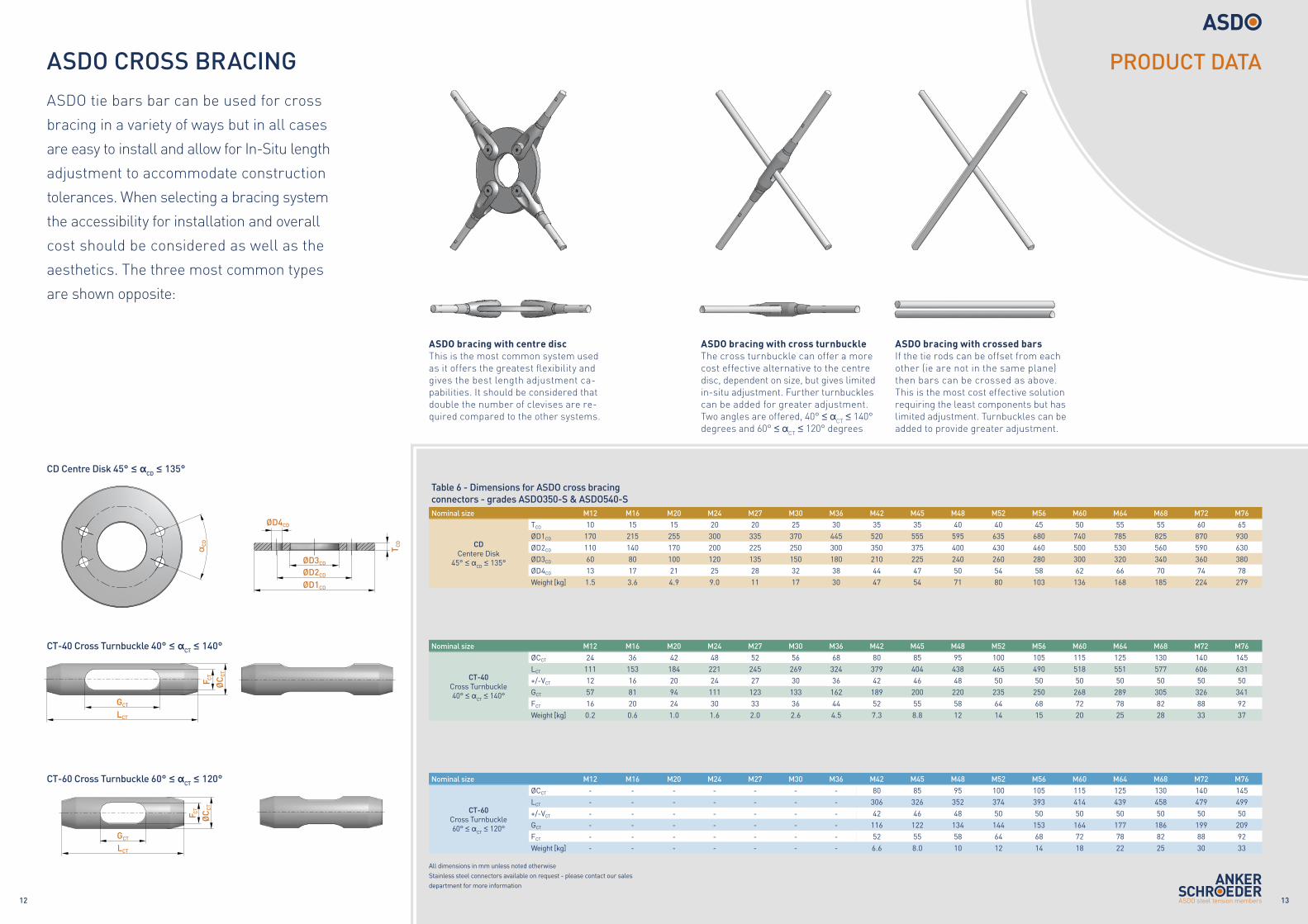
ASDO CROSS BRACING
Table 6 - Dimensions for ASDO cross bracing connectors - grades ASDO350-S & ASDO540-SNominal size M12 M16 M20 M24 M27 M30 M36 M42 M45 M48 M52 M56 M60 M64 M68 M72 M76
CD Centere Disk
45° ≤ αCD ≤ 135°
TCD 10 15 15 20 20 25 30 35 35 40 40 45 50 55 55 60 65ØD1CD 170 215 255 300 335 370 445 520 555 595 635 680 740 785 825 870 930ØD2CD 110 140 170 200 225 250 300 350 375 400 430 460 500 530 560 590 630ØD3CD 60 80 100 120 135 150 180 210 225 240 260 280 300 320 340 360 380ØD4CD 13 17 21 25 28 32 38 44 47 50 54 58 62 66 70 74 78Weight [kg] 1.5 3.6 4.9 9.0 11 17 30 47 54 71 80 103 136 168 185 224 279
Nominal size M12 M16 M20 M24 M27 M30 M36 M42 M45 M48 M52 M56 M60 M64 M68 M72 M76
CT-40Cross Turnbuckle40° ≤ αCT ≤ 140°
ØCCT 24 36 42 48 52 56 68 80 85 95 100 105 115 125 130 140 145LCT 111 153 184 221 245 269 324 379 404 438 465 490 518 551 577 606 631+/-VCT 12 16 20 24 27 30 36 42 46 48 50 50 50 50 50 50 50GCT 57 81 94 111 123 133 162 189 200 220 235 250 268 289 305 326 341FCT 16 20 24 30 33 36 44 52 55 58 64 68 72 78 82 88 92Weight [kg] 0.2 0.6 1.0 1.6 2.0 2.6 4.5 7.3 8.8 12 14 15 20 25 28 33 37
Nominal size M12 M16 M20 M24 M27 M30 M36 M42 M45 M48 M52 M56 M60 M64 M68 M72 M76
CT-60Cross Turnbuckle60° ≤ αCT ≤ 120°
ØCCT - - - - - - - 80 85 95 100 105 115 125 130 140 145LCT - - - - - - - 306 326 352 374 393 414 439 458 479 499+/-VCT - - - - - - - 42 46 48 50 50 50 50 50 50 50GCT - - - - - - - 116 122 134 144 153 164 177 186 199 209FCT - - - - - - - 52 55 58 64 68 72 78 82 88 92Weight [kg] - - - - - - - 6.6 8.0 10 12 14 18 22 25 30 33
CD Centre Disk 45° ≤ αCD ≤ 135°
ASDO tie bars bar can be used for cross
bracing in a variety of ways but in all cases
are easy to install and allow for In-Situ length
adjustment to accommodate construction
tolerances. When selecting a bracing system
the accessibility for installation and overall
cost should be considered as well as the
aesthetics. The three most common types
are shown opposite:
ASDO bracing with centre discThis is the most common system used as it offers the greatest flexibility and gives the best length adjustment ca-pabilities. It should be considered that double the number of clevises are re-quired compared to the other systems.
ASDO bracing with cross turnbuckleThe cross turnbuckle can offer a more cost effective alternative to the centre disc, dependent on size, but gives limited in-situ adjustment. Further turnbuckles can be added for greater adjustment. Two angles are offered, 40° ≤ αCT ≤ 140° degrees and 60° ≤ αCT ≤ 120° degrees
ASDO bracing with crossed barsIf the tie rods can be offset from each other (ie are not in the same plane) then bars can be crossed as above. This is the most cost effective solution requiring the least components but has limited adjustment. Turnbuckles can be added to provide greater adjustment.
CT-40 Cross Turnbuckle 40° ≤ αCT ≤ 140°
CT-60 Cross Turnbuckle 60° ≤ αCT ≤ 120°
PRODUCT DATA
All dimensions in mm unless noted otherwiseStainless steel connectors available on request - please contact our sales department for more information
αC
D
ØD4CD
ØD3CD
ØD2CD
ØD1CD
T CD
GCT
GCT
LCT
LCT
F CT
F CT
ØC
CT
ØC
CT
1514
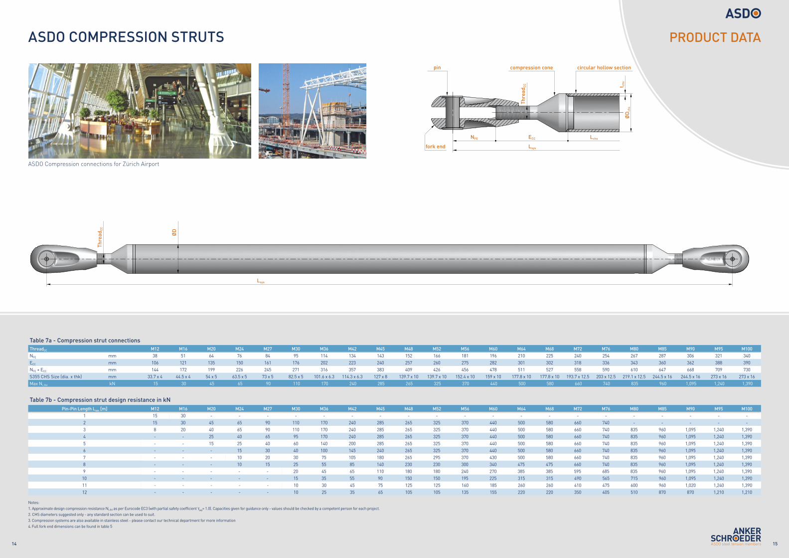
ASDO COMPRESSION STRUTS
ASDO Compression connections for Zürich Airport
Table 7a - Compression strut connectionsThreadCC M12 M16 M20 M24 M27 M30 M36 M42 M45 M48 M52 M56 M60 M64 M68 M72 M76 M80 M85 M90 M95 M100NFE mm 38 51 64 76 84 95 114 134 143 152 166 181 196 210 225 240 254 267 287 306 321 340ECC mm 106 121 135 150 161 176 202 223 240 257 260 275 282 301 302 318 336 343 360 362 388 390NFE + ECC mm 144 172 199 226 245 271 316 357 383 409 426 456 478 511 527 558 590 610 647 668 709 730S355 CHS Size (dia. x thk) mm 33.7 x 4 44.5 x 4 54 x 5 63.5 x 5 73 x 5 82.5 x 5 101.6 x 6.3 114.3 x 6.3 127 x 8 139.7 x 10 139.7 x 10 152.4 x 10 159 x 10 177.8 x 10 177.8 x 10 193.7 x 12.5 203 x 12.5 219.1 x 12.5 244.5 x 16 244.5 x 16 273 x 16 273 x 16Max Nc,Rd kN 15 30 45 65 90 110 170 240 285 265 325 370 440 500 580 660 740 835 960 1,095 1,240 1,390
Table 7b - Compression strut design resistance in kNPin-Pin Length Lsys [m] M12 M16 M20 M24 M27 M30 M36 M42 M45 M48 M52 M56 M60 M64 M68 M72 M76 M80 M85 M90 M95 M100
1 15 30 - - - - - - - - - - - - - - - - - - - -2 15 30 45 65 90 110 170 240 285 265 325 370 440 500 580 660 740 - - - - -3 8 20 40 65 90 110 170 240 285 265 325 370 440 500 580 660 740 835 960 1,095 1,240 1,3904 - - 25 40 65 95 170 240 285 265 325 370 440 500 580 660 740 835 960 1,095 1,240 1,3905 - - 15 25 40 60 140 200 285 265 325 370 440 500 580 660 740 835 960 1,095 1,240 1,3906 - - - 15 30 40 100 145 240 265 325 370 440 500 580 660 740 835 960 1,095 1,240 1,3907 - - - 10 20 30 75 105 180 265 295 370 430 500 580 660 740 835 960 1,095 1,240 1,3908 - - - 10 15 25 55 85 140 230 230 300 340 475 475 660 740 835 960 1,095 1,240 1,3909 - - - - - 20 45 65 110 180 180 240 270 385 385 595 685 835 960 1,095 1,240 1,390
10 - - - - - 15 35 55 90 150 150 195 225 315 315 490 565 715 960 1,095 1,240 1,39011 - - - - - 10 30 45 75 125 125 160 185 260 260 410 475 600 960 1,020 1,240 1,39012 - - - - - 10 25 35 65 105 105 135 155 220 220 350 405 510 870 870 1,210 1,210
PRODUCT DATA
Notes: 1. Approximate design compression resistance Nc,Rd as per Eurocode EC3 (with partial safety coefficient γM0= 1.0). Capacities given for guidance only - values should be checked by a competent person for each project.2. CHS diameters suggested only - any standard section can be used to suit.3. Compression systems are also available in stainless steel - please contact our technical department for more information4. Full fork end dimensions can be found in table 5
ØD
chs
pin compression cone circular hollow section
fork end
NFE ECC
Lsys
Lsys
Lchs
t chs
Thre
adC
C
Thre
adC
C
ØD
1716
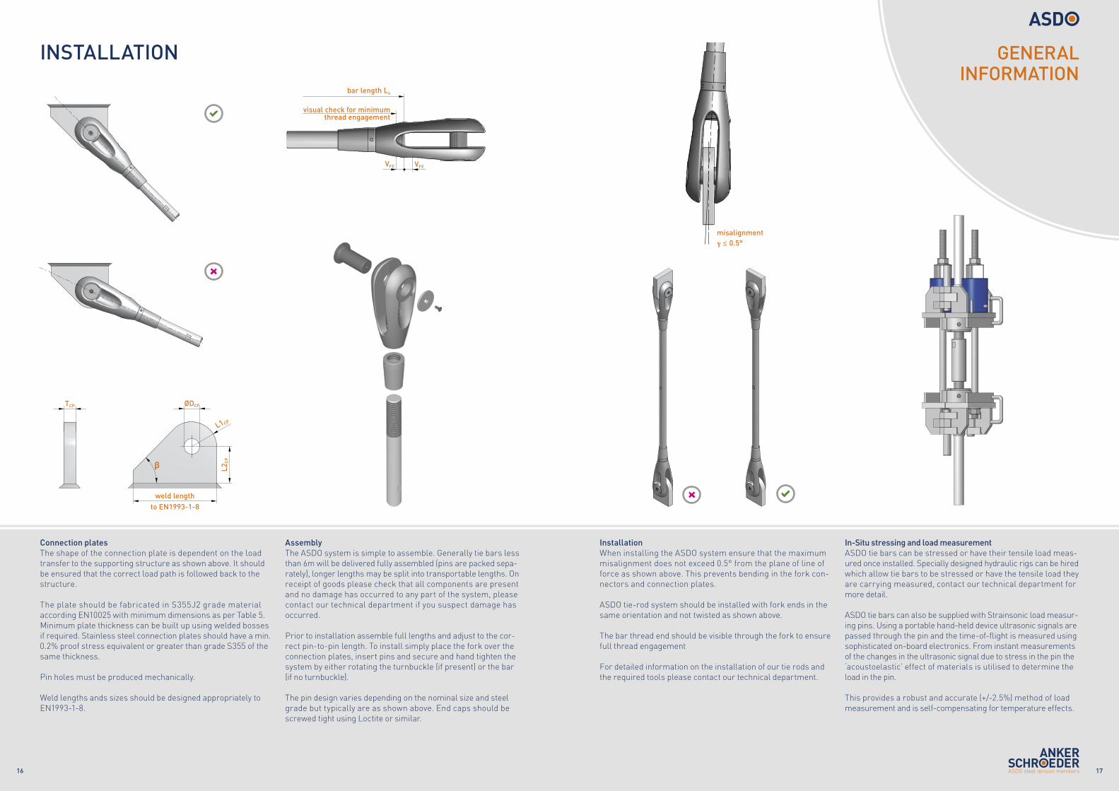
INSTALLATION
Connection platesThe shape of the connection plate is dependent on the load transfer to the supporting structure as shown above. It should be ensured that the correct load path is followed back to the structure.
The plate should be fabricated in S355J2 grade material according EN10025 with minimum dimensions as per Table 5. Minimum plate thickness can be built up using welded bosses if required. Stainless steel connection plates should have a min. 0.2% proof stress equivalent or greater than grade S355 of the same thickness.
Pin holes must be produced mechanically.
Weld lengths ands sizes should be designed appropriately toEN1993-1-8.
InstallationWhen installing the ASDO system ensure that the maximum misalignment does not exceed 0.5° from the plane of line of force as shown above. This prevents bending in the fork con-nectors and connection plates.
ASDO tie-rod system should be installed with fork ends in the same orientation and not twisted as shown above.
The bar thread end should be visible through the fork to ensure full thread engagement
For detailed information on the installation of our tie rods and the required tools please contact our technical department.
misalignment γ ≤ 0.5°
AssemblyThe ASDO system is simple to assemble. Generally tie bars less than 6m will be delivered fully assembled (pins are packed sepa-rately), longer lengths may be split into transportable lengths. On receipt of goods please check that all components are present and no damage has occurred to any part of the system, please contact our technical department if you suspect damage has occurred.
Prior to installation assemble full lengths and adjust to the cor-rect pin-to-pin length. To install simply place the fork over the connection plates, insert pins and secure and hand tighten the system by either rotating the turnbuckle (if present) or the bar (if no turnbuckle).
The pin design varies depending on the nominal size and steel grade but typically are as shown above. End caps should be screwed tight using Loctite or similar.
GENERAL INFORMATION
In-Situ stressing and load measurementASDO tie bars can be stressed or have their tensile load meas-ured once installed. Specially designed hydraulic rigs can be hired which allow tie bars to be stressed or have the tensile load they are carrying measured, contact our technical department for more detail.
ASDO tie bars can also be supplied with Strainsonic load measur-ing pins. Using a portable hand-held device ultrasonic signals are passed through the pin and the time-of-flight is measured using sophisticated on-board electronics. From instant measurements of the changes in the ultrasonic signal due to stress in the pin the ‘acoustoelastic’ effect of materials is utilised to determine the load in the pin.
This provides a robust and accurate (+/-2.5%) method of load measurement and is self-compensating for temperature effects.
A- A ( 1 : 5 )
A
TCP ØDCP
L2C
P
L1CP
weld lengthto EN1993-1-8
β
VFEVFE
visual check for minimumthread engagement
bar length La
1918
GENERAL INFORMATION
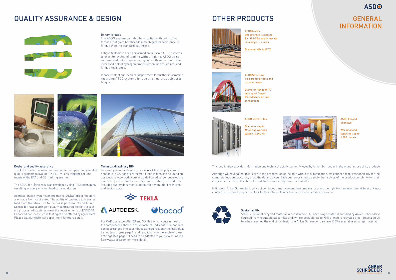
OTHER PRODUCTS
This publication provides information and technical details currently used by Anker Schroeder in the manufacture of its products.
Although we have taken great care in the preparation of the data within this publication, we cannot accept responsibility for the completeness and accuracy of all the details given. Each customer should satisfy themselves of the product suitability for their requirements. The publication of this data does not imply a contractual offer.
In line with Anker Schroeder’s policy of continuous improvement the company reserves the right to change or amend details. Please contact our technical department for further information or to ensure these details are current.
SustainabilitySteel is the most recycled material in construction. All anchorage material supplied by Anker Schroeder is sourced from reputable steel mills and, where possible, up to 90% of melt is recycled steel. Once a struc-ture has reached the end of it’s design life Anker Schroeder bars are 100% recyclable as scrap material.
ASDO Marine Upset forged tie bars to EN1993-5 for use in marine retaining structures
Diameter M64 to M170
ASDO Structural Tie bars for bridges and dynamic loads
Diameter M64 to M170with upset forged, threaded or cast end connections
ASDO Micro-Piles
Diameters up to M160 and working loads > 4,500 kN
ASDO Forged Shackles
Working load capacities up to 1,500 tonnes
QUALITY ASSURANCE & DESIGN
Technical drawings / BIMTo assist you in the design process ASDO can supply compo-nent data in CAD and BIM format. Links to files can be found on our website www.asdo.com and a dedicated server ensures the user always downloads the latest information, for BIM this includes quality documents, installation manuals, brochures and design loads.
For CAD users we offer 2D and 3D files which contain most of the components shown in this brochure. Individual components can be arranged into assemblies as required, only the individual tie rod length (see page 9) and restrictions to the angle of cross bracings (see page 12) need to be adapted to your project needs. See www.asdo.com for more detail.
Dynamic loadsThe ASDO system can also be supplied with cold rolledthreads that gives bar threads a much greater resistance to fatigue than the standard cut thread.
Fatigue tests have been performed on full scale ASDO systems to over 2m cycles of loading without failing. ASDO do not recommend hot dip galvanising rolled threads due to the increased risk of hydrogen embrittlement and much reduced fatigue resistance.
Please contact our technical department for further information regarding ASDO systems for use on structures subject to fatigue.
Design and quality assuranceThe ASDO system is manufactured under independently audited quality systems to ISO 9001 & EN1090 ensuring the require-ments of the ETA and CE marking are met.
The ASDO fork (or clevis) was developed using FEM techniques resulting in a very efficient load carrying design.
As most tension systems on the market ASDO fork connectors are made from cast steel. The ability of castings to transfer load from the structure to the bar is paramount and Anker Schroeder have a stringent quality control regime for the cast-ing process. All castings meet the requirements of EN10340. Enhanced non-destructive testing can be offered by agreement. Please call our technical department for more detail.

Anker Schroeder ASDO GmbHHannöversche Straße 4844143 DortmundGermany
Phone +49 231 51701-0Fax +49 231 [email protected] Printed June 2015, see www.asdo.com for the latest version