Embed Size (px)
Citation preview

AD
AD-E403 369
Technical Report ARMET-TR-11031
M119 HOWTIZER SADDLE GUN FIRE FINITE ELEMENT ANALYSIS
R. Terhune S. McDonald
M. Kotliar
December 2011
U.S. ARMY ARMAMENT RESEARCH, DEVELOPMENT AND ENGINEERING CENTER
Munitions Engineering Technology Center
Picatinny Arsenal, New Jersey
Approved for public release; distribution is unlimited.
2D\\UUQfT7

The views, opinions, and/or findings contained in this report are those of the author(s) and should not be construed as an official Department of the Army position, policy, or decision, unless so designated by other documentation.
The citation in this report of the names of commercial firms or commercially available products or services does not constitute official endorsement by or approval of the U.S. Government.
Destroy this report when no longer needed by any method that will prevent disclosure of its contents or reconstruction of the document. Do not return to the originator.

REPORT DOCUMENTATION PAGE Form Approved OMB No. 0704-01-0188
The public reporting burden for this collection of information is estimated to average 1 hour per response, including the time for reviewing instructions, searching existing data sources, gathering and maintaining the data needed, and completing and reviewing the collection of information Send comments regarding this burden estimate or any other aspect of this collection of information, including suggestions for reducing the burden to Department of Defense, Washington Headquarters Services Directorate for Information Operations and Reports (0704-0188), 1215 Jefferson Davis Highway, Suite 1204, Arlington, VA 22202-4302. Respondents should be aware that notwithstanding any other provision of law, no person shall be subject to any penalty for failing to comply with a collection of information if it does not display a currently valid OMB control number PLEASE DO NOT RETURN YOUR FORM TO THE ABOVE ADDRESS.
1. REPORT DATE (DD-MM-YYYY) December 2001
2. REPORT TYPE Final
3. DATES COVERED (From - To) December 2010 to May 2011
4. TITLE AND SUBTITLE
M119 HOWITZER SADDLE GUN FIRE FINITE ELEMENT ANALYSIS
5a. CONTRACT NUMBER
5b. GRANT NUMBER
5c. PROGRAM ELEMENT NUMBER
6. AUTHORS
R. Terhune, S. McDonald, and M. Kotliar
5d. PROJECT NUMBER
5e. TASK NUMBER
5f. WORK UNIT NUMBER
7. PERFORMING ORGANIZATION NAME(S) AND ADDRESS(ES) U.S. Army ARDEC Fuze & Precision Armaments/Muntions Systems & Technology Directorate (RDAR-MEF-E/MEM-A) Picatinny Arsenal, NJ 07806-5000
8. PERFORMING ORGANIZATION REPORT NUMBER
9. SPONSORING/MONITORING AGENCY NAME(S) AND ADDRESS(ES) U.S. Army ARDEC, ESIC Knowledge & Process Management (RDAR-EIK) Picatinny Arsenal, NJ 07806-5000
10. SPONSOR/MONITOR'S ACRONYM(S)
11. SPONSOR/MONITOR'S REPORT NUMBER(S)
Technical Report ARMET=TR-11031 12. DISTRIBUTION/AVAILABILITY STATEMENT
Approved for public release; distribution is unlimited.
13. SUPPLEMENTARY NOTES
14. ABSTRACT
The M119 howitzer is the current fielded 105-mm artillery weapon. It is undergoing upgrades to the fire control system in which they will be adding new components and brackets to the existing system. Finite element analysis (FEA) was performed to determine the stress contours along the side of the saddle (a sub- system of the howitzer) in regions where holes will be added for fire control brackets. The FEA results were validated by strain gauge data from live fire test and provided the needed insight for verifying the hole locations.
15. SUBJECT TERMS
M119 Saddle
Howitzer Fire control
105 mm Artillery Finite element analysis (FEA) Strain gauge
16. SECURITY CLASSIFICATION OF:
a. REPORT U
b. ABSTRACT U
c. THIS PAGE U
17. LIMITATION OF ABSTRACT
SAR
18. NUMBER OF PAGES
19
19a. NAME OF RESPONSIBLE PERSON R. Terhune 19b. TELEPHONE NUMBER (Include area
code) (973) 724-1383 Standard Form 298 (Rev. 8/98)
Prescribed by ANSI Std. Z39.18
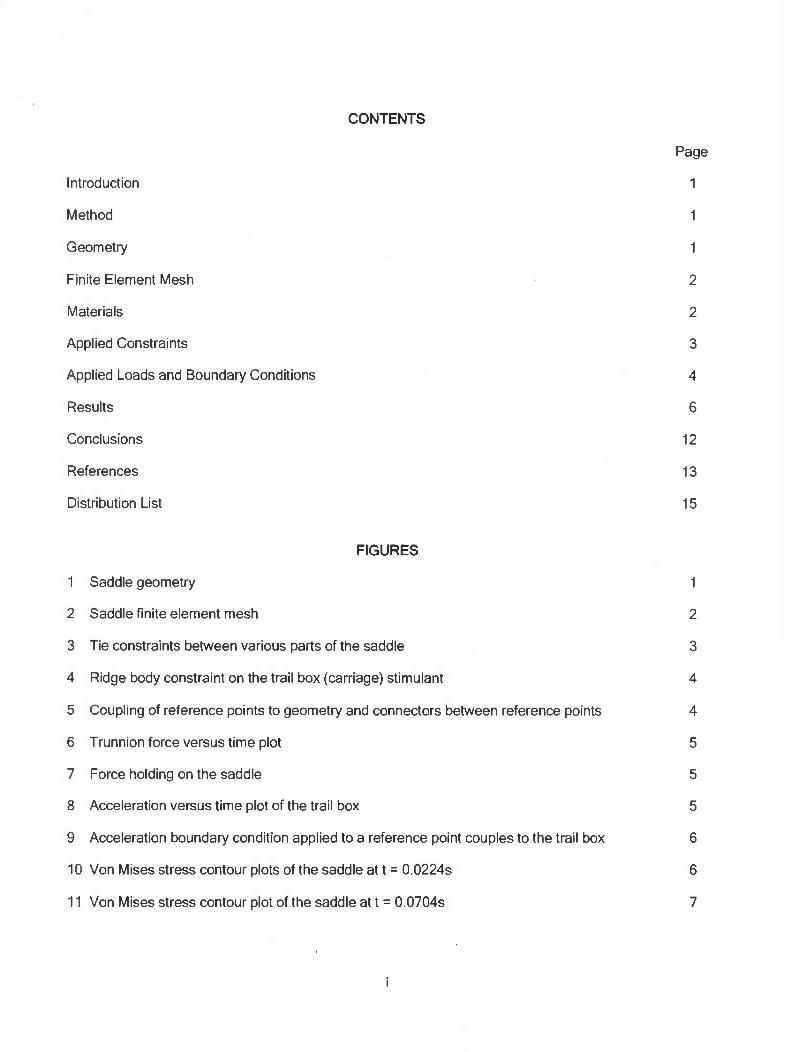
CONTENTS
Page
Introduction 1
Method 1
Geometry 1
Finite Element Mesh 2
Materials 2
Applied Constraints 3
Applied Loads and Boundary Conditions 4
Results 6
Conclusions 12
References 13
Distribution List 15
FIGURES
1 Saddle geometry 1
2 Saddle finite element mesh 2
3 Tie constraints between various parts of the saddle 3
4 Ridge body constraint on the trail box (carriage) stimulant 4
5 Coupling of reference points to geometry and connectors between reference points 4
6 Trunnion force versus time plot 5
7 Force holding on the saddle 5
8 Acceleration versus time plot of the trail box 5
9 Acceleration boundary condition applied to a reference point couples to the trail box 6
10 Von Mises stress contour plots of the saddle at t = 0.0224s 6
11 Von Mises stress contour plot of the saddle at t = 0.0704s 7

FIGURES (continued)
Page
12 Strain gauge locations 1 to 4 used to compare to live-fire testing 7
13 Strain gauge 1 comparison 8
14 Strain gauge 2 comparison 9
15 Strain gauge 3 comparison 9
16 Strain gauge 4 comparison 10
17 Strain gauge locations 17 to 18 used to compare to live-fire testing 10
18 Strain gauge 17 comparison 11
19 Strain gauge 18 comparison 11
20 Strain gauge 19 comparison 12
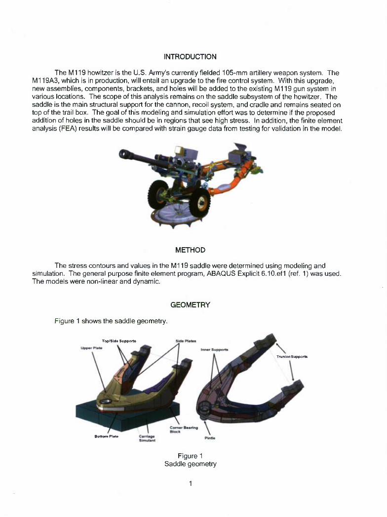
INTRODUCTION
The M119 howitzer is the U.S. Army's currently fielded 105-mm artillery weapon system. The M119A3, which is in production, will entail an upgrade to the fire control system. With this upgrade, new assemblies, components, brackets, and holes will be added to the existing M119 gun system in various locations. The scope of this analysis remains on the saddle subsystem of the howitzer. The saddle is the main structural support for the cannon, recoil system, and cradle and remains seated on top of the trail box. The goal of this modeling and simulation effort was to determine if the proposed addition of holes in the saddle should be in regions that see high stress. In addition, the finite element analysis (FEA) results will be compared with strain gauge data from testing for validation in the model.
METHOD
The stress contours and values in the M119 saddle were determined using modeling and simulation. The general purpose finite element program, ABAQUS Explicit 6.10.ef1 (ref. 1) was used. The models were non-linear and dynamic.
GEOMETRY
Figure 1 shows the saddle geometry.
Top/Side Supports
Tru n ton Su pports
Bottom Plata
Figure 1 Saddle geometry
1

FINITE ELEMENT MESH
The finite element (FE) mesh is displayed in figure 2. All the sheet metal parts were modeled with 8-node continuum shell elements with five integration points through thickness. There are 111,065 elements in total in the model consisting of 42,839 8-node hexahedral elements, 66,926 8-node continuum shell hexahedral elements, and 1,300 10-node tetrahedral elements.
Figure 2 Saddle finite element mesh
MATERIALS
The model used linear elastic material properties. The M119 uses a British stainless steel, but for the purpose of this analysis, a 17-4 stainless steel was used since its material properties match well.
Part Material Modulus (psi)
Poisson Ratio
Density (lbrsA2/in"4)
Yield (psi)
UltimateTrue Plastic Strain
UltimateTrue Stress (psi)
Entire Assembly 17-4 S.S. 2.85E+7 0.27 .000732 125,000 0.11 163,850
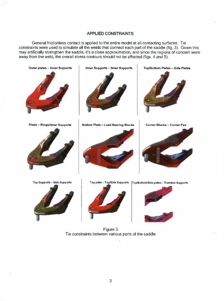
APPLIED CONSTRAINTS
General frictionless contact is applied to the entire model at all contacting surfaces. Tie constraints were used to simulate all the welds that connect each part of the saddle (fig. 3). Given this may artificially strengthen the saddle, it's a close approximation, and since the regions of concern were away from the weld, the overall stress contours should not be affected (figs. 4 and 5).
Outer plates - Inner Supports Inner Supports - Inner Supports Top/Bottom Plates - Side Plates
Pintle - Rings/Inner Supports Bottom Plate - Load Bearing Blocks Corner Blocks - Corner Pad
Top Support* - Sid* Supports Top plat* - Top/Side Support* Top/Bottom/Side plat** - Trunnion Support*
Figure 3 Tie constraints between various parts of the saddle
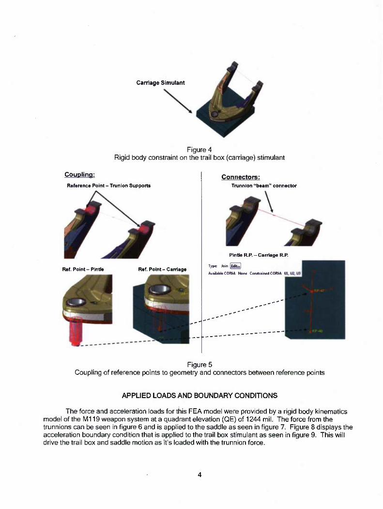
Carriage Simulant
Figure 4 Rigid body constraint on the trail box (carriage) stimulant
Coupling:
Reference Point - Trunion Supports
Ref. Point - PintJe Ref. Point - Carriage
Connectors: Trunnion "beam" connector
Pintle R.P. - Carriage R.P.
Type loin JMU.|
Avirijble OHM None Constiamed CORM: Ul,
Figure 5 Coupling of reference points to geometry and connectors between reference points
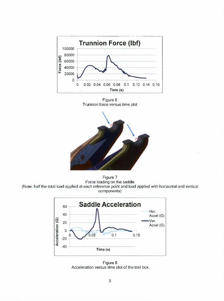
APPLIED LOADS AND BOUNDARY CONDITIONS
The force and acceleration loads for this FEA model were provided by a rigid body kinematics model of the M119 weapon system at a quadrant elevation (QE) of 1244 mil. The force from the trunnions can be seen in figure 6 and is applied to the saddle as seen in figure 7. Figure 8 displays the acceleration boundary condition that is applied to the trail box stimulant as seen in figure 9. This will drive the trail box and saddle motion as it's loaded with the trunnion force.
100000
5-. 80000
§. 60000
a 40000 o "• 20000
Trunnion Force (Ibf)
0 0.02 0.04 0.06 0.08 0.1 0.12 0.14 0.16
Time (s)
Figure 6 Trunnion force versus time plot
Figure 7 Force loading on the saddle
(Note: half the total load applied at each reference point and load applied with horizontal and vertical components)
60 Saddle Acceleration Hor. Accel (G)
•Ver. Accel (G)
0.15
Time (s)
Figure 8 Acceleration versus time plot of the trail box

Figure 9 Acceleration boundary condition applied to a reference point couples to the trail box
RESULTS
The FE analysis converged to a solution and produced confident results. At the first peek in the force loading, the stress contour can be seen in figure 10. In figure 11, the stress contour of the saddle at the force maximum is seen. The regions of concern are circled in red. Overall, the regions where holes are being added see low stresses during gun fire.
Saddle Von Mises Stress Plot (Ultimate: 163,850psi) t = 0224s
Trunnion Force (Ibf) 90000 80000 70000
£ 60000 =•50000 £ 40000 ° 30000 •
20000 10000
0
Lower Stress Regions along side plates Good locations for addition of holes
Figure 10 Von Mises stress contour plots of the saddle at t=0.0224s

Sack) la Von Mises Stress Plot (Ultimate 163 850psi) t= 0704s
Lower Stress Regions along side plates Good locations tor addition of holes
Figure 11 Von Mises stress contour plot of the saddle at t=0.0704s
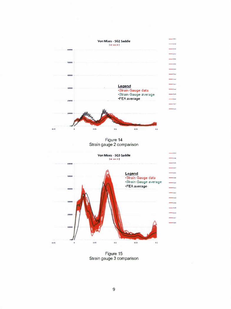
The Von Mises stress values at specific locations on the saddle were recorded in the analysis so they could be compared to strain gauge derived stress values. Figures 12 and 17 show the locations and element numbers that were chosen. Stress comparisons for gauges 1 to 4 are displayed in figures 13 through 16 and for gauges 17 to 19 in figures 18 through 20.
Gauge Part Instance Element Number
SG1 119200_12591876_PLATE 341
SG2 118200_12591876_PL ATE 1096
SG3 119200_12591876_PLATE 1397
SG4 119200_12591858_PLATE 463
6 90"
Figure 12 Strain gauge locations 1 to 4 used to compared to live fire testing

189-
1 78-
Figure 12 (continued)
MM*
Von Mises-SGI Saddle | « uu n |
-MW
MM*
4MM
Legend •Strain Gauge data •Strain Gauge average •FEA average
-MM
Figure 13 Strain gauge 1 comparison
Von M.ses-SG2 Saddle HIM
Legend •Strain Gauge data •Strain Gauge average •FEA average
Figure 14 Strain gauge 2 comparison
Von Mises - SG3 Saddle | Of 1244 n I
Legend •Strain Gauge data •Strain Gauge average •FEA average
-*„•*.
Figure 15 Strain gauge 3 comparison
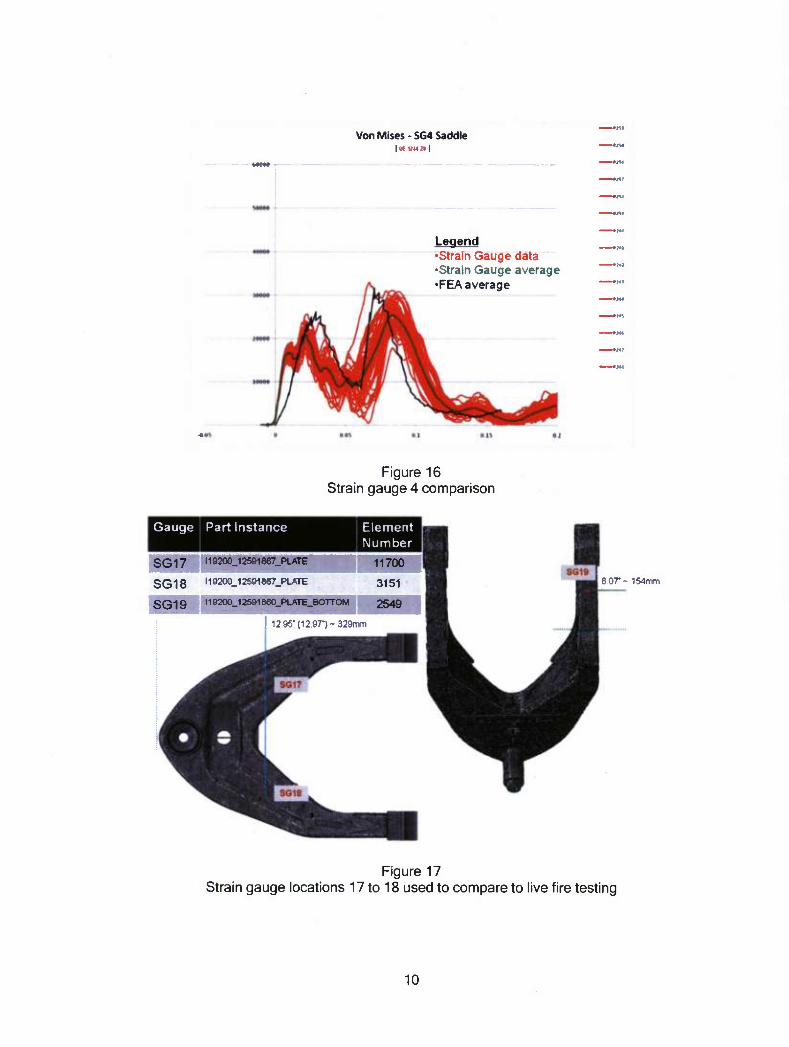
Von Mises - SG4 Saddle |<* uua|
Legend •Strain Gauge data •Strain Gauge average •FEA average
Figure 16 Strain gauge 4 comparison
Gauge Part Instance Element Number
I19200_12591867_PLATE 11700
SG18 H9200_125918e7_PLATE 3151
SG19 W 9200-125S1860_PLATE_BOTTOM 2549
12 95' (12 97") -329mm
6 07-- 154mm
Figure 17 Strain gauge locations 17 to 18 used to compare to live fire testing
10

Stress - RG17 LSaddle ocaoon oenoorj oci2«a i GEM r si- OEM asm
Legend •Strain Gauge data •Strain Gauge average •FEA average
OM I 1 Oil OH 0 1*. .lx
Figure 18 Strain gauge 17 comparison
Stress - RG18 RSaddle OE*oozt oEtina ot\zua .£»;•» o£soz»s»rr
Legend •Strain Gauge data •Strain Gauge average •FEA average
Figure 19 Strain gauge 18 comparison
11

OBCZ7
Stress - RG19 SaddleForeArm oaooz» oenoozt OEISWZ* ICKEMZTSKT OEHZIS
Legend •Strain Gauge data •Strain Gauge average •FEA average
Figure 20 Strain gauge 19 comparison
CONCLUSIONS
The model and simulation was able to capture the high rate gun fire event with confidence and proved to be an effective aid in the redesign to the weapon. Mesh refinement models were also run to verify that continuum shell elements produce accurate stress results as compared to typical three- dimensional hexahedral elements. Overall, the analysis results provided accurate stress contours over the saddle in the regions of concern. Validation and correlation was achieved as the finite element analysis stress values matched up well with live fire test strain gauge data at multiple locations on the saddle. With confidence in the model results, decisions can be made with regards to what locations would be appropriate for adding holes in the saddle for new components.
12

REFERENCES
1. "ABAQUS User Manual V6.10.1," Dassault Sysstems 2004-2010.
13

DISTRIBUTION LIST
U.S. Army ARDEC ATTN: RDAR-EIK
RDAR-GC RDAR-ME, J. Hedderich RDAR-MEF, W. Smith RDAR-MEF-E, R. Terhune (2) RDAR-MEF-E, D. Troast
A. Totten RDAR-WSW-I, M. Kotliar
S. McDonald Picatinny Arsenal, NJ 07806-5000
Defense Technical Information Center (DTIC) ATTN: Accessions Division 8725 John J. Kingman Road, Ste 0944 Fort Belvoir, VA 22060-6218
Commander Soldier and Biological/Chemical Command ATTN: AMSSB-CII, Library Aberdeen Proving Ground, MD 21010-5423
Director U.S. Army Research Laboratory ATTN: AMSRL-CI-LP, Technical Library Bldg. 4600 Aberdeen Proving Ground, MD 21005-5066
Chief Benet Weapons Laboratory, WSEC U.S. Army Research, Development and Engineering Command Armament Research, Development and Engineering Center ATTN: RDAR-WSB Watervliet, NY 12189-5000
Director U.S. Army TRADOC Analysis Center-WSMR ATTN: ATRC-WSS-R White Sands Missile Range, NM 88002
Chemical Propulsion Information Agency ATTN: Accessions 10630 Little Patuxent Parkway, Suite 202 Columbia, MD 21044-3204
GIDEP Operations Center P.O. Box 8000 Corona, CA 91718-8000
15