Embed Size (px)
Citation preview

PCM -17 RUE ERNEST LAVAL-BP 35-92173 VANVES CEDEX France
INSTRUCTION MANUAL PLEASE KEEP FOR FUTURE REFERENCE
PCM - MOINEAU
Series M Type 011M6F – 075M6F – 1M6F – 2M6F – 3M6F
M1 – Monobloc installation
Serial No. Year of manufacture
Document No.: NIPMM1F03A Date approved: December 2005
Issue date: MARCH 07

DECLARATION OF INCORPORATION
We declare that the subassembly described in the technical description cannot be put into service until the machine in which it is to be incorporated has been declared compliant with the provisions of machine directive 98/37/CE modified 98/79/CE and with the related national legislation.
The subassembly complies with harmonised standards EN ISO 12100.
Vanves, 28/07/2005
For company – NAME and FUNCTION Innovation Director
Luc Chatelain

CONTENTS
0. INTRODUCTION 5
0.1 General Information 5
0.2 Limits of Guarantee 5
0.3 Safety and Environment 6
1. CHARACTERISTICS AND INSTALLATION 7
1.1 Operating Principle 7
1.2 Characteristics 8 1.2.1 Build Properties 8 1.2.2 Operating Characteristics 10
1.3 Installation 12 1.3.1 Installation Precautions 12 1.3.2 Connecting the Pipes 13 1.3.3 Anchoring 13 1.3.4 Connecting the Motor Unit 13
2. OPERATION 14
2.1 Commissioning 14 2.1.1 Before Start-up 14 2.1.2 Start-up 14
2.2 Normal Operating Procedure 15 2.2.1 Start-up Procedure 15 2.2.2 General Operating Instructions 15 2.2.3 Cleaning 15 2.2.4 Shutdown Procedure 15
2.3 Operating procedure in the event of an incident 15
2.4 Automation 16
3. MAINTENANCE 17
3.1 List of spare parts 17
3.2 Handling Equipment and Procedure 20
3.3 Storage Conditions 21

3.4 Preventive Maintenance 21 3.4.1 Periodic Inspection 21 3.4.2 Lubrication 21 3.4.3 Torque 22 3.4.4 Specialist Tools 22
3.5 Corrective Maintenance 23 3.5.1 Troubleshooting 23 3.5.2 Pump Disassembly (see diagram in Section 3: Maintenance) 25 3.5.3 Pump Reassembly (see diagram in Section 3: Maintenance) 29
3.6 Storing the Equipment when not in Use 33 3.6.1 Preserving the Rubber Components 33
3.7 Accessories 33
4. APPENDICES 34

Page 5
0. INTRODUCTION
0.1 General Information
The pump you have just acquired was manufactured and inspected with the greatest of care.
This manual aims to help you keep your pump in good working order.
The information contained in this manual may not be copied or published in any form whatsoever, whether by printing, photography, recording on microfilm or any other means (electronic or mechanical) without the prior written consent of PCM Pompes SA.
The information given in this document is subject to change without notice. PCM Pompes SA or its representatives decline all responsibility in the event of damage resulting from the use of this manual. This exemption from responsibility applies to damage of all types, including (without any limit) compensatory damages, whether direct or indirect, loss of data, profits or return of capital, loss or damage caused to the property of others, and third-party claims. PCM Pompes SA or its representatives accept no responsibility and do not guarantee the accuracy, completeness, or up-to-date nature of the information contained in this manual.
Markings
Information shown on the pump motor unit or on an identification plate attached to the pump:
a) Manufacturer name and address.b) Serial number.c) Maximum allowable flow rate at 0 bar or rotation rate of pump motor unit.d) Maximum allowable pump pressure, according to its motor.e) Customer reference (optional).This information is essential when ordering spare parts (contact PCM Services).
Pump characteristics (e.g. flow rate, pressure, speed of rotation, construction, direction of rotation of pump, etc.) must not be modified without written permission from PCM Services.
0.2 Limits of Guarantee
Before performing any servicing on the pump, please check that all necessary precautions have been taken: pump switched off, upstream and downstream valves closed, pipework cleaned and purged, electrical power supply disconnected, and all the usual steps to be applied according to the personnel safety regulations in force.
On receiving the pump, examine it immediately to check that it shows no obvious sign of damage. If it is visibly damaged, write a clear annotation on the carrier’s documents stating that the merchandise was received damaged and briefly describing the nature of the damage. If you decide to accept such equipment, send a registered letter with return receipt, to reach the carrier within forty-eight hours, with a copy to PCM Services.

Page 6
Storage and handling conditions are given in detail in Section 3, Para. 3.2 and 3.3.
To avoid all risk of accident or damage (in particular, when hazardous products are being pumped), it is essential to refrain from using this equipment for an application other than the one originally intended (refer to technical description in Appendix).
To maintain the original qualities of the pump and to preserve the PCM guarantee on the equipment as well as compliance with the machines directive, it is essential to use PCM parts only.
0.3 Safety and Environment PCM is committed to an environmental protection initiative in accordance with the recommendations of the ISO 14001 standard.
PCM has set up a system through which its customers can ask PCM to handle the disposal of waste material (used pumps and spare parts). This system is especially useful for the disposal of parts containing elastomers, such as the stators of Moineau pumps or tubes from peristaltic pumps.
All returns must be sent to the PCM factory, carriage paid. The equipment must be clean, with the pump and drive completely emptied of products, and must arrive with the sheet entitled: risk prevention (see Section 4: Appendices).
All items returned for this purpose must be legibly marked with the words ‘Equipment to be recycled’.
Send to :
PCM Rue René Moineau 49123 CHAMPTOCE SUR LOIRE FRANCE

Page 7
1. CHARACTERISTICS AND INSTALLATION
1.1 Operating Principle
The PCM Moineau progressive cavity pump (or eccentric screw pump) essentially consists of two internal helical gears, which both have the following features:
- The stator, which is the external element, has one more tooth than the rotor, which is the internal element.
- In any given cross-section, each section of the rotor is in contact with the stator.
- The pitches of the helices of the two elements are in a ratio according to the number of teeth.
The rotation generates an axial displacement, from the suction to the discharge, of the closed cavities bounded by the rotor and stator.
The PCM MOINEAU pump is a volumetric pump whose capacity is equal to the volume of a cavity.
The stator of pumps is said to be ‘floating’, meaning that it has one free end. This principle, associated with an elastic coupling, simplifies the transmission of the rotational movement between the drive and the rotor.
Mounting the stator in this floating configuration provides the following advantages:
Rotor
Stator
Discharge
Spacer
Suction port Body Pin
Mechanical seal

Page 8
Direction of rotation (Note: This pump is not reversible!)
The pump’s direction of rotation is shown on the upper part of the pump body.
The pump is designed to be used in one directly of rotation only. It is up to the installer to check the revolving field of the electrical installation to ensure that the pump is running in the correct direction of rotation.
1.2 Characteristics
1.2.1 Build Properties
Defined in the table below
Component 011M6F 075M6F 1M6F 2M6F 3M6F
Stator NBR / CSM / FKM / CR Plot NBR / CSM / FKM / CR
Single mechanical
seal Carbon/Silicon carbide
Rotor X30Cr13
Body/Port/ Spacer
EN-GJL250
The material descriptions comply with the AFNOR standard.
NOTE: By default, our pumps are protected by a particular paint. The procedure and details of the application of this paint are defined in the technical description.
Page 9
Z
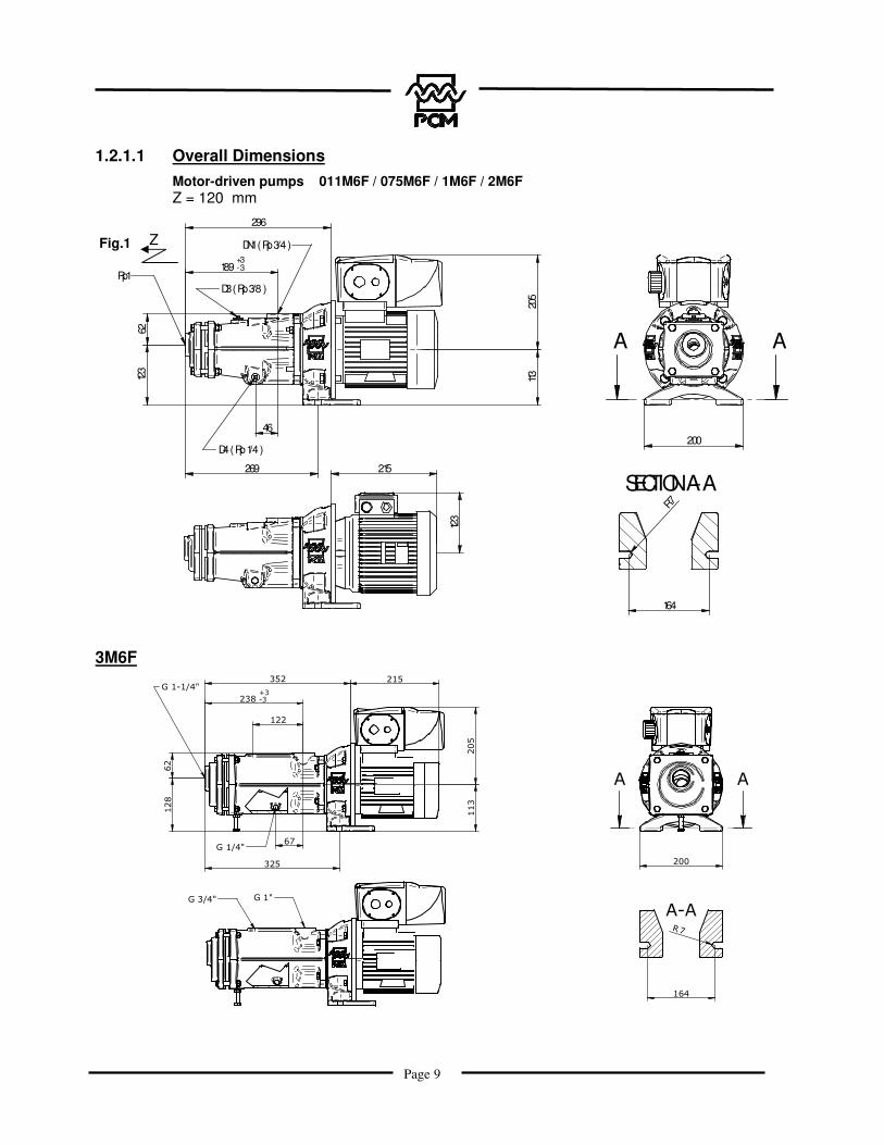
1.2.1.1 Overall Dimensions Motor-driven pumps 011M6F / 075M6F / 1M6F / 2M6F Z = 120 mm
189+3-3
6212
3
269
205
Rp1
DN1 ( Rp 3/4 )
D4 ( Rp 1/4 )200
A A
SECTION A-A
164
R7
46
113
296
D3 ( Rp 3/8 )
123
215
3M6F ���
������
��
��
���
������
� �
�����
��
����
��
�����
�����
���
���
���
�������
Fig.1 Z

Page 10
1.2.2 Operating Characteristics
Pump characteristics (e.g. flow rate, pressure, speed of rotation, construction, etc.) must not be modified without written permission from PCM Services.
They are indicated in the technical description of the equipment delivered. The A-weighted equivalent acoustic pressure level of pumps manufactured by PCM Pompes is below 80 dB(A), in compliance with the European directive in force concerning noise from motor-driven equipment.
M Series floating stator Moineau pumps are used in the following industries: starch industry, construction, ceramics, sanitation & environmental, oil production, petrochemical industry, petroleum, soap manufacture, etc.
With their robust design, MF Series Moineau pumps are used to convey a variety of liquids: clear, viscous, abrasive, heterogeneous, charged, fragile, or emulsifying.
IMPORTANT NOTE
The maximum temperature for use is determined by the stator material and the specifications given in the technical description provided in Appendix.
The maximum speeds are given by the curves on the following page.
Do not use the pump under conditions other than those described in this document without first obtaining authorisation from PCM Services.
Pump performance curves
The rotational speeds and pressures shown on the following curves represent performance characteristics obtained with water at 20°C. When operating conditions differ from this standard, the performance characteristics must be adjusted according to:
- Product characteristics (viscosity, fragility, abrasion).
- The characteristics of the application (operating speed, discharge pressure, available NPSH).
The following curves were generated under the following conditions:
- Based on water at 20°C
- Discharge pressure = 0 bar

Page 11
0 250 750500 1000 1500
500
1000
1500
2000
2500
3000
Q en l/h(Débit)
N en tr/mn
Type
011M6F
075M6F
1M6F
2M6F
For more precise details, look at the curve for your pump, or ask PCM Services to send you
this information.
Base: water Temperature: 20°C Discharge pressure: 0 bar
Speed of rotation (RPM)
Q (1/h) (Flow rate)
3M6F

Page 12
1.3 Installation All Moineau pumps are inspected in our workshop before dispatch.
1.3.1 Installation Precautions
It is important to leave enough space around the pump to allow access for maintenance and adjustments. Avoid installing the pump in a location where the ambient temperature might not be within the operating temperature limits of the pump (refer to the technical description in Appendix). For an outdoor installation, it is recommended that you provide a protective covering above the equipment and a freeze protection system.
Caution! It is essential to install the pump horizontally, because in a vertical installation, the mechanical seal can be damaged unless precautions are taken.
It is also recommended that you install a removable fitting for ease of servicing the entire pump motor unit. The pump must not support the weight of the pipework. A safety valve or pressure-sensitive switch and a pressure gauge are located at the discharge for the purposes of protection and to allow the pump's operating characteristics to be monitored. A dry running protection probe protects the pump when there is a shortage of the product to be pumped. Please ask PCM about its wide selection of accessories to suit your requirements.
Tips for Optimum Pump Operation
a) Preferably the pump is in floaded suction condition.allb) Place the pump as close as possible to the suction point.c) If a valve is present in the circuit, it is ESSENTIAL to provide a safety valve or pressure-sensitive switch.
NOTE: Without protection on the circuit, a valve at the discharge is often the cause of operating errors leading to damage to the pump or pipework.
Dry running protection probe
To use
Return to tank or drain
From tank

Page 13
1.3.2 Connecting the Pipes
An easily removable component should be installed on the stator end side. This allows the stator and the rotor to be removed easily (see dimension Z, Para. 1.2.1.1), without removing the whole pump from its mounting site. The weights of the pipes must not be supported by the pump. The allowable torques and forces on the fittings are given in Para. 1.2.1.
1.3.3 Anchoring
The pump and its drive mechanism must be secured to an adequately sized concrete block using screws and rawl plugs or foundation bolts. The unit shall be placed on a flat surface so that the spacer is maintained on the installation plane. If necessary, wedge the assembly to ensure that the unit is stable (refer to overall dimensions, Para. 1.2.1.1).
1.3.4 Connecting the Motor Unit
Caution! All procedures must be performed by qualified personnel. PCM Pompes declines all responsibility if this requirement is not fulfilled. Before performing any connections, ensure that the electrical power supply has the characteristics listed on the motor plate. There is also a connection diagram in the motor terminal box (instructions in Appendix).
For thermal protection: the setting is the current indicated on the motor plate.
When all connections have been made, the motor should be run at low speed for a few seconds (if possible using a mechanical or frequency variator) and you should check the direction of rotation of the motor as compared to the arrow marked on it.
Caution! Pumps do not tolerate dry running.

Page 14
2. OPERATION
2.1 Commissioning
2.1.1 Before Start-up
Ensure that:
_ Electrical connections are compliant. _ The reduction gear has been filled with lubricant or the level is adequate. _ The venting plug on the reduction gear is present and its protection has been removed. _ The direction of shaft rotation corresponds to the specified direction of circulation. _ The product to be pumped is present in the tank and the pump body. _ The mechanical seal is lubricated if the pump is equipped with a self-lubricating seal. _ All valves installed upstream and downstream from the pump are open. _ The variator end stops are properly adjusted. _ The temperature and type of product to be pumped are compliant.
2.1.2 Start-up
NEVER ALLOW THE PUMP TO RUN DRY!
To guard against this possibility, PCM may recommend a dry running protection system.
If the pump is not charged, you are advised to fill the pump body by hand. If the pump is temporarily not primed, the small amount of liquid remaining in the pump is enough to lubricate the stator until the next priming. During the first few minutes of operation, check for the following:
_ The liquid being pumped reaches the end of the discharge pipe. _ The pump does not vibrate. _ No unusual noise. _ Sealing system functions well (refer to the specialist documentation in the appended instructions, according to the sealing system). _ Check that the pressure stabilises, if a pressure gauge is installed. _ No abnormal heating in the following areas:
· Stator· Sealing system.
Check that the following parameters match the design parameters of the pump: _ Speed, flow rate, pressure, viscosity, and temperature.
If the values are not those indicated, consult PCM Services.

Page 15
2.2 Normal Operating Procedure
2.2.1 Start-up Procedure
Check the following points before each start-up: _ Presence of the product to be pumped. _ Suction and discharge pipe valves are open. _ Correct temperature of the product to be pumped.
2.2.2 General Operating Instructions
During operation, ensure that: _ The pump is continuously supplied with the product and with its source of energy. _ The discharge pressure remains stable and below the maximum capacity of the pump. _ The temperature of the product being pumped remains within the operating limits. _ The operating instructions in force on the production site are observed.
2.2.3 Cleaning
External Cleaning
Any soiling likely to damage the paint and corrode the pump must be removed from the equipment.
Internal Cleaning
Cleaning procedures and frequency of cleaning depend on the specific use of the pump and on the product being pumped. The basic procedure, however, is described below.
With the pump in operation, supply it at the suction with a cleaning product that is compatible with the product to be pumped and with the materials of which the pump is made. The cleaning time will be defined by the process using the pump. At the end of this time, shut down the pump in accordance with Para. 2.2.4.
2.2.4 Shutdown Procedure
The shutdown procedure depends on the type of product being pumped. Refer to the specific characteristics located in the technical description in the Appendix.
The shutdown procedure is therefore defined by the process.
The minimum procedure, however, is to switch off the pump and then to close the suction and discharge valves.
Caution! If the product decants, the pump must be cleaned so that it can then be re-started without damage.
2.3 Operating procedure in the event of an incident In the event of operating malfunctions such as the following: _ Pump does not start up. _ Pump does not prime itself. _ Flow rate is too low or irregular. _ Pump stops running.

Page 16
_ Pump does not deliver. _ Pump is unusually noisy. Proceed as follows: _ Shut down the pump in accordance with the shutdown procedure described in Para. 2.2.4. _ Hydraulically isolate the pump (suction and discharge). _ Refer to Para. 3.5.1 - Troubleshooting.
2.4 Automation
The use of devices that automatically enable or disable pump operation is recommended. Examples: pressure-sensitive switch, valves with electrical position contact, dry running protection probe (capacitance probe).

Page 17
3. MAINTENANCE
3.1 List of spare parts
For the list of spare parts for your pump, contact PCM Services giving the serial number of your equipment. This number is shown on the manufacturer identification plate (see Para. 0.1). You can ask us to overhaul your pump. Within three days of receiving it, we will supply a quotation showing the cost of the overhaul and how long it will take to do. Contact PCM Services. PCM Services address:
PCM Centre de services Rue René Moineau 49123 CHAMPTOCE SUR LOIRE Tel: 0892.460.333 *
*: (0.34 � incl. tax/min)

Page 18

Page 19
011M6F 075M6F 1M6F 2M6F 3M6FITEM DESCRIPTION Q N° N° N° N° N°
1STATOR PCM 1 56 248 15 123 15 121 27 466 #########
11PIN 1
13SEAL 1
16/17GASKET 1
20ROTOR 1 56 250 001 14 762 001 14 442 001 T200148001 T20015001
34SHAFT RING 1
36CTRL SHAFT 1
50BODY 1
54PORT 1
57MS SUPPORT 1
88SPACER 1
90SEAL 2
102WASHER 4
102AWASHER 4
104SCREW 4
104ASCREW 4
107NUT 8
110PLUG 1
110APLUG 1
111PLUG SEAL 1
227WASHER 4
242WASHER 2
250SCREW 4
14 574 160
40 700 160
C09056D186
14 595 051
14 598 051
C06111A000
T360082001
T570017014
T880056051
15 074 160
40040 046J
40041 046J
40319 046J
40041 046J
40306 046J
40 498 062
40 500 062
40 700 160
93505.009
14 741 015
40030 046J

Page 20
3.2 Handling Equipment and Procedure
To handle the complete pump, refer to the procedure in force and comply with legislation concerning the safety of personnel. Slinging must be performed by trained, qualified personnel in accordance with the instructions given in this manual. Any failure to observe this rule releases PCM from all responsibility.
Before lifting the pump, ensure that all its components are securely fastened to each other. For small pumps, slinging has not been provided for.
Page 21
3.3 Storage Conditions A) In standard PCM packaging
. Pumps and pump parts must be stored in their original packaging, in a stable position, protected from impact, and in a dry location.
B) After unwrapping
. Protect the equipment from impact and from dust.
C) Packaged according to S.E.I. 4c
Every six months, . Replace the desiccant pouches, . Check the machined surfaces and grease them if necessary.
NOTE: Once a month, run the pump 4 or 5 revolutions with the motor fan.
3.4 Preventive Maintenance
All maintenance procedures must be performed by trained, qualified personnel in compliance with the instructions given in this manual.
Any failure to observe this rule releases PCM from all responsibility.
Before performing any servicing on the pump, please check that all necessary precautions have been taken: pump switched off, upstream and downstream valves closed, pipes cleaned and purged, electrical power supply disconnected and made inaccessible. All the usual precautions must be taken, in accordance with the texts in force regarding the safety of personnel.
3.4.1 Periodic Inspection
For operation eight hours per day, five days per week:
_ Complete leaktightness of the pump: Once a week. _ Tightness of the assembly mounting hardware (port, stator, body, spacer, drive): Once a month. _ Level of lubricant in the drive, if applicable: Once a month. _ Anchoring: Once a year. _ Motor current and cleanliness of drive ventilation grille: Once a month. _ Condition of power supply electrical cable sheaths: Once a year.
3.4.2 Lubrication
The pump drive is supplied with oil. Check the oil level before putting the pump in service.
Consult the manufacturer documentation supplied in Appendix for the precautions to be taken when lubricating the drive, where applicable.

Page 22
The following table indicates the recommended lubricants to be used when servicing the pump:
Component to be lubricated Recommended lubricants Supplier Connection between reduction gear/Control shaft (36) GERALYN 2 grease FUCHS LUBRITECH
Stator Item 1 (for assembly) GLYCERINE
3.4.3 Torque
The general torque values for the mounting hardware are given in the following table:
Diameter of mounting hardware
Min. torque Max. torque
M4 0.9 Nm 1.6 Nm M5 1.8 Nm 3.3 Nm M6 3.1 Nm 5.6 Nm M8 7.4 Nm 13 Nm M10 15 Nm 27 Nm M12 30 Nm 45 Nm M14 52 Nm 74 Nm M16 61 Nm 110 Nm
3.4.4 Specialist Tools
No specialist tools.

Page 23
3.5 Corrective Maintenance
3.5.1 Troubleshooting Incident
Causes The
pum
p do
es n
ot s
tart.
Pum
p no
long
er d
eliv
ers
_ P
ump
does
not
prim
e its
elf.
_ P
ump
stop
s ru
nnin
g.
Flow
rate
too
low
Insu
ffici
ent d
isch
arge
pr
essu
re
Driv
e is
ove
rload
ed
Pum
p is
noi
sy o
r vib
rate
s
Leak
in s
haft
seal
Pre
mat
ure
stat
or w
ear
Pre
mat
ure
roto
r wea
r
Flow
rate
is n
ot c
onst
ant
Join
ts d
eter
iora
te q
uick
ly
Solu
tions
(s
ee p
arag
raph
3.5
.1.1
)
The stator is swollen. x x x x x 1
Rotor drive system is broken. x x x x 2
Product temperature is too high. x x x x x x x x x x 3
Sedimentation or precipitation of the fluid in the pump body x x x x x x x x x 4
The solid bodies contained in the liquid are too voluminous. x x x x x x x 5
The electrical installation is not compliant. x x x x x x 6
The devices driving the pump are worn or broken. x x x x x x x x 7
Pump is blocked by a foreign body. x x x x x x x 8
The stator has become hard and brittle. x x x x x x x x x 9
The stator is sectioned at its rim. x x x 10
The stator is worn. x x x x x x 11
The rotor is worn. x x x x x x 12
Leak in mechanical seal. x x 13
Incorrect direction of rotation. x x 14
Product temperature is lower than expected. x x x x 15
Net positive suction head is too low NPSHd<NPSHr x x x x x x x x 16
The pump suction is aspirating air. x x x x x 17
Speed of rotation is too low. x x x 18
Pump installation location, pipework and accessories should all be checked. x x x x x x x x x 19
The pump is running dry. x x x x 20
Viscosity of the pumped product is higher than expected. x x x x 21
Pressure at discharge is too high. x x x x x x x x x 22
Speed of rotation is too high. x x x x x 23
For a new pump or new stator: excessive static tightening. x x 24
Shaft is damaged (according to model). x x x x x x 25
The roller bearings are worn (according to model). x x 26
Stability of pump motor unit (according to model). x 27

Page 24
3.5.1.1 Solutions
1) The stator material swells when in contact with the product being pumped. Check that thematerial and the product are those specified in the order. If necessary, contact PCM Services.
2) Determine the cause of failure by checking points 1, 3, 4, 5, 8, 22, and 23, and then replace thedamaged parts.
3) The operating temperature limit is defined according to the stator material.
4) Clean the pump body and rinse the pump after each use.
5) Remove these bodies using a strainer, or consult PCM Services about obtaining another pump.
6) Check the network voltage, motor connections, circuit breaker calibration, and number ofphases.
7) Replace defective parts and check the load on the drive.
8) Disassemble the pump, clean it, and replace any defective components.
9) Check that the temperature is not higher than initially planned and that the product beingpumped is the intended product. For any change of parameters, consult PCM Services to determine a different pump construction.
10) This type of damage is typically caused by an overpressure. Consult PCM Services.
11) Replace the stator and check the condition of the rotor.
12) Determine the cause of the wear: abrasion, corrosion, cavitation; consult PCM Services todefine a new rotor material if necessary, and install the new part.
13) Remove the mechanical seal and replace it with a new one.
14) Change the electrical connections.
15) Contact PCM Services, who will recommend a tighter stator.
16) Reduce head loss in the suction pipe, lower the temperature, and raise the suction level.
17) Check the installation for leaks.
18) Consult PCM Services to determine the best way to increase the speed.
19) Check all pipes for obstruction by a foreign body, for a defective valve, for a continuous leak:improperly sealed valve, leaky poppet, etc.
20) Re-arrange the overall layout of the installation, or provide a dry running protection system.
21) For any viscosity change, consult PCM Services who will re-calculate the parameters.
22) Measure the pressure using a pressure gauge, and compare it to the pressure stated in thetechnical description.
23) Consult PCM Services to determine the best way to decrease the speed.
24) Fill the pump, and rotate the motor screw about ten revolutions by hand.
25) Replace the shaft and the mechanical seal.
26) Remove the bearing or reduction gear, and replace the roller bearings and seals.
27) Adjust the feet or check the mountings.

Page 25
3.5.2 Pump Disassembly (see diagram in Section 3: Maintenance)
Before performing any servicing on the pump, please check that all necessary precautions have been taken: upstream and downstream valves closed, pipework cleaned and purged, electrical power supply disconnected, and all the usual steps to be applied according to the personnel safety regulations in force.
DISASSEMBLY CHART
3.5.2.1 Disassembling the Pump on the Operating Site
Obey the instructions given in Para. 3.5.2. Drain the pump by removing the plug, Item 110 A. Remove the pump from the installation and isolate it from the electrical circuit whilst identifying the motor connections (to obtain the correct direction of rotation after reassembly).
3.5.2.2 Removing the Stator Item 1
Drain the pump by removing the plug, Item 110 A. Withdraw the removable component of the pipework on the stator port side, Item 54. Disconnect the screws, nuts, and washer, Items 102/104/107. Remove the port, Item 54, from the stator, Item 1. Remove the motor cowl. Extract the stator, Item 1, by using a spanner to rotate the drive shaft.
Check the condition of the stator.
Items 102/104/107
Item 54
Drive shaft
Item 110A

Page 26
3.5.2.3 Disassembling the Shafting, Item 20/11
Perform the steps listed in Para. 3.5.2.2. Use appropriate means to support the motor unit. Remove the four screws and washers, Item 102A/104A, securing the spacer Item 88 to the body Item 50. Remove the body, Item 50.
Use a strap wrench to turn the pin, Item 11, whilst immobilising the drive shaft in order to free the shafting, Item 20/11, from the reduction gear outlet shaft. Isolate the shafting, Item 20/11, and place it in a safe location, protected from impacts. It is recommended that you check the condition of the seals, Items 13 and 90, and if necessary replace them during reassembly.
Item 102A / 104A
Item 50
Item 20 /11
Item 90
Item 88
Item 13

Page 27
Caution! During reassembly, coat the bore of the control shaft that receives the reduction gear output shaft with grease before reinstalling the collet.
3.5.2.4 Removal of Rotor Assembly Item 20 and Pin Item 11
Perform the steps listed in Para. 3.5.2.2. Perform the steps listed in Para. 3.5.2.3.
Using the plats at the end of the rotor, loosen the pin Item 11 with the strap wrench. It is recommended that you check the condition of the seal, Item 90, and if necessary replace it during reassembly.
3.5.2.5 Disassembly of Mechanical Seal, Item 16/17
Perform the steps listed in Para. 3.5.2.2. Perform the steps listed in Para. 3.5.2.3. Slide the rotating part, Item 16, of the mechanical seal on the control shaft, Item 36, by handling the bellows and the spring only. Remove the seal support, Item 57, from the spacer, Item 88. Press on the rear face of the counter-bearing, Item 17, and extract it from the seal support, Item 57.
Item 20
Item 11
Item 57
Item 16 / 17
Item 88
Item 36
Item 90

Page 28
3.5.2.6 Removing the Shaft
First, de-couple the spacer, Item 88, from the drive system by removing the screws, washers, and nuts Items 250/227/107.
Next, loosen the shaft ring, Item 34, and slide the control shaft, Item 36.
Item 88
Drive system
Items 250/227/107
Item 34
Item 36

Page 29
3.5.3 Pump Reassembly (see diagram in Section 3: Maintenance)
To preserve optimum operating characteristics for the pump, it is essential to use original PCM parts only. Pump maintenance must be performed by qualified personnel only, in compliance with the recommendations in force.
REASSEMBLY
3.5.3.1 Reinstalling the Shaft, Item 36, and Collet, Item 34
Caution! During reassembly, coat the bore of the shaft, Item 36, that receives the motor output shaft with grease before reinstalling the collet, Item 34 (see Para. 3.4.2).
Slide the shaft, Item 36, on the drive shaft.
Tighten the screw of the collet, Item 34 (see Para. 3.4.3).
Item 36
Item 34
Page 30
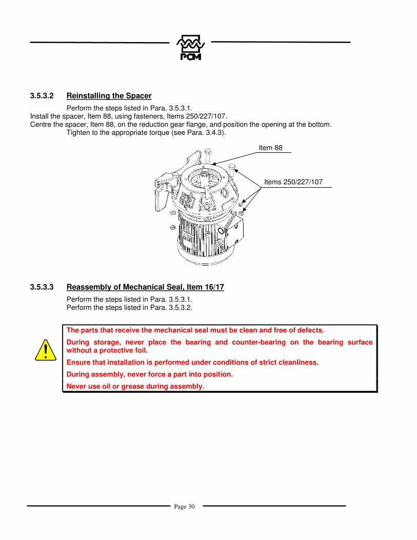
3.5.3.2 Reinstalling the Spacer
Perform the steps listed in Para. 3.5.3.1. Install the spacer, Item 88, using fasteners, Items 250/227/107. Centre the spacer, Item 88, on the reduction gear flange, and position the opening at the bottom.
Tighten to the appropriate torque (see Para. 3.4.3).
3.5.3.3 Reassembly of Mechanical Seal, Item 16/17
Perform the steps listed in Para. 3.5.3.1. Perform the steps listed in Para. 3.5.3.2.
The parts that receive the mechanical seal must be clean and free of defects.
During storage, never place the bearing and counter-bearing on the bearing surface without a protective foil.
Ensure that installation is performed under conditions of strict cleanliness.
During assembly, never force a part into position.
Never use oil or grease during assembly.
Item 88
Items 250/227/107

Page 31
Slowly and steadily push the counter-bearing Item 17 into the housing of its support Item 57. Place the rotating unit (spring unit) Item 16 on the control shaft Item 36 by turning it slightly clockwise. To reduce friction during assembly, the elastomer bellows and the output shaft must be moistened using low surface tension water (i.e. water with a rinsing agent added), or with a rinsing agent alone. Eliminate scratches from the bearing surfaces using ethyl alcohol and cellulose cloths (no fabrics, no rags!). After that, do not touch the bearing surfaces with your bare fingers.
3.5.3.4 Reassembling the Shafting, Item 20/11
Perform the steps listed in Para. 3.5.3.1. Perform the steps listed in Para. 3.5.3.2. Perform the steps listed in Para. 3.5.3.3. Ensure that the seal, Item 90, is located on the shaft, Item 36. Tighten the pin, Item 11, coated with Freinfilet® thread locking compound (see Para. 3.4.2) with the washer, Item 242, on the shaft, Item 36.
Tighten to the appropriate torque (see Para. 3.4.3).
Items 17/57
Item 16
Item 90
Item 242 Item 11
Coated: Freinfilet®

Page 32
3.5.3.5 Reinstalling the Rotor
Perform the steps listed in Para. 3.5.3.1. Perform the steps listed in Para. 3.5.3.2. Perform the steps listed in Para. 3.5.3.3. Perform the steps listed in Para. 3.5.3.4. Check that the seal, Item 90, is present. Tighten the rotor, Item 20, coated with Freinfilet® (see Para. 3.4.2) with the washer, Item 242, on the pin, Item 11, whilst immobilising the drive shaft.
Tighten to the appropriate torque (see Para. 3.4.3).
3.5.3.6 Reinstalling the Body Item 50 and Stator Item 1
Perform the steps listed in Para. 3.5.3.1. Perform the steps listed in Para. 3.5.3.2. Perform the steps listed in Para. 3.5.3.3. Perform the steps listed in Para. 3.5.3.4. Perform the steps listed in Para. 3.5.3.5. Reinstall the body using the fasteners.
Lubricate the stator (see Para. 3.4.2). Install the stator. Position the port, Item 54, at the end of the stator, Item 1. Lock the assembly using the screws, nuts, and washers. Tighten to the appropriate torque (see Para. 3.4.3).
Reinstall the motor cowl.
Item 20
Item 90
Item 242

Page 33
3.5.3.7 Reinstalling the Pump on the Operating Site
Place the pump in position, seal the connectors according to type, and connect the motor (refer to all of Section 1.3). Familiarise yourself with the characteristics of the product in order to take all necessary precautions concerning the safety of personnel. Apply the start-up instructions (see Para. 2.1.1, and then 2.1.2 and 2.2.1).
3.6 Storing the Equipment when not in Use
Proceed as follows: – Release the suction and discharge pressures.– Drain the pipework and the pump.– Clean the pipework and pump using a product that is compatible with the product to be pumpedand the pump materials. – For a better cleaning result, run the pump.– Shut down the pump.– Isolate the pump from the rest of the circuit.
3.6.1 Preserving the Rubber Components
We recommend that you store all rubber parts in a cool location, away from light to avoid damage by UV rays.
3.7 Accessories
Special instructions supplied in Appendix.
Page 34
4. APPENDICES
Technical description Accessories (optional) Automatic control (optional) Risk prevention.

Page 35
RISK PREVENTION PCM EQUIPMENT RETURN
COMPANY USING THE EQUIPMENT …………………………………………………………………………………………. ……………………………………………………………………………………………………………………………… ………………………………………………………
ACTIVITY …………………………………………………………………………………..……………………………
Equipment Part No. ……………………………………………………………………….
Is the equipment liable to present any particular risks by being used? yes ���� no ����
CHEMICAL RISKS yes � no �
Product or Substance Mode of Contamination Prevention
BIOLOGICAL RISKS yes � no �
Biological Agents Mode of Contamination Prevention