Embed Size (px)
Citation preview

M. Steller
Space Research Institute, Graz
EDI Gun FM2Performed Tests and
Results
1IWF/ÖAW GRAZ
2IWF/ÖAW GRAZ
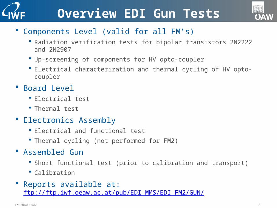
Overview EDI Gun Tests Components Level (valid for all FM’s)
Radiation verification tests for bipolar transistors 2N2222 and 2N2907 Up-screening of components for HV opto-coupler Electrical characterization and thermal cycling of HV opto-coupler
Board Level Electrical test Thermal test
Electronics Assembly Electrical and functional test Thermal cycling (not performed for FM2)
Assembled Gun Short functional test (prior to calibration and transport) Calibration
Reports available at: ftp://ftp.iwf.oeaw.ac.at/pub/EDI_MMS/EDI_FM2/GUN/

3IWF/ÖAW GRAZ
Radiation Verification Test
NPN Transistor 2N2222 Two batches, two different lots Dose rate 25krad/h = 6,94rad/sec First batch: hFE ~150 => ~55 @75 krad
Second batch: hFE ~160 => ~25 @ 75krad
PNP Transistor 2N2907 Two batches, two different lots Dose rate 25krad/h = 6,94rad/sec First batch: hFE ~200 => ~65 @75 krad Second batch: hFE ~145 => ~50 @ 75krad
4IWF/ÖAW GRAZ
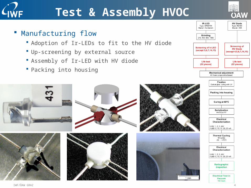
Test & Assembly HVOC
Manufacturing flow Adoption of Ir-LEDs to fit to the HV diode Up-screening by external source Assembly of Ir-LED with HV diode Packing into housing

5IWF/ÖAW GRAZ
Up-screening of HVOC
Screening and serialization performed by SACTEC Procedure follows IEEE-INST-002 (EDI-IWF-PRO-0028) Mechanical tests were excluded
Ir-Diode HV-Diode

6IWF/ÖAW GRAZ
Selection of HVOC Electrical characterisation
Five HV levels 1kV to 5kV Seven current levels for Ir-LED
(1, 2, 5, 10, 15, 20, 25mA)
Detailed characterisation for selection (since FM3) HV sweep from 0 to 5kV with 100V steps
Seven current levels for Ir-LED(1, 2, 5, 10, 15, 20, 25mA)
HV-Supply
1kV
Current SourceKeithley 6221
10mAUSB
I(µA)
1kV
U(V)
Fluke 89 IV
Keithley 2601

7IWF/ÖAW GRAZ
Board Level Tests
Electrical Test Board mounted onto dedicated test adapter with spring loaded electrical
contacts Standard BLT uses in- and output pins only Additional test points in case detailed measurements necessary Pre-defined step procedures Test is performed semi-automatically Scripts control stimuli and read-out Scripts for generation of graphs

8IWF/ÖAW GRAZ
Board Level Test DEFL1
Functional Test Supply current REF voltage to HV controller
(D2, D3, D6, D7) Sweep input from 0 to 3.5V Trimming in case deviation
is larger than 0.2% Sweep repeated in case of trimming Check of resistor ring
(generation of REF voltages)
Thermal Test Ambient pressure, -20°C ... 70°C Recording of HV output, HK values
and supply currents
Report EDI-IWF-REP-0264

9IWF/ÖAW GRAZ
Results for DEFL1
HV Outputs Deflection D2: 0/+3000V => 0/+2998V Deflection D3 : 0/+3000V => 0/+3004V Deflection D6 : 0/+3000V => 0/+3006V Deflection D7 : 0/+3005V => 0/+2997V
Inputs to HV Controller Deflection D2: 998.6V => 997V 2501.4V => 2497V
Deflection D3: 998.6V => 998V 2501.4V => 2503V Deflection D6: 998.6V => 999V 2501.4V => 2505V Deflection D7: 998.6V => 996V 2501.4V => 2498V

10IWF/ÖAW GRAZ
Board Level Test DEFL2
Functional Test Supply current REF voltage to HV controller
(D1, D4, D5, D8) Sweep input from 0 to 3.5V Trimming in case deviation is larger than 0.2% Sweep repeated in case of trimming Check of resistor ring
(generation of REF voltages) Check of HK multiplexer (test signal 3.5V)
Thermal Test Ambient pressure, -20°C ... 70°C Recording of HV output, HK values
and supply currents
Report EDI-IWF-REP-0265

11IWF/ÖAW GRAZ
Results for DEFL2
HV Outputs Deflection D1: 0/+3000V => 0/+3006V Deflection D4 : 0/+3000V => 0/+3002V Deflection D5 : 0/+3000V => 0/+3000V Deflection D8 : 0/+3005V => 0/+3005V
Inputs to HV Controller Deflection D1: 998.6V => 999V 2501.4V => 2505V
Deflection D4: 998.6V => 999V 2501.4V => 2502V Deflection D5: 998.6V => 997V 2501.4V => 2500V Deflection D8: 998.6V => 999V 2501.4V => 2504V

12IWF/ÖAW GRAZ
Board Level Test OPT_DEFL
Functional Test Supply current REF voltage to HV controller
(UD, UI) Sweep input from 0 to 3.5V Trimming in case deviation is larger than
0.2% Sweep repeated in case of trimming Check of HK multiplexer (test signal 3.5V) Calibration of temperature sensor
Thermal Test Ambient pressure, -20°C ... 70°C Recording of HV output, HK values
and supply currents
Report EDI-IWF-REP-0266

13IWF/ÖAW GRAZ
Results for OPT_DEFL
HV Outputs U_Deflector: 0/+3000V => -1/+3007V U_Injector: 0/+2000V =>
0/+2000V

14IWF/ÖAW GRAZ
Board Level Test BEAM
Functional Test Supply current REF voltage to HV controller
(Anode, Focus, Cathode) Sweep input from -1.5 to 3.5V
(range depends on channel) Trimming in case deviation is larger than
0.2% Sweep repeated in case of trimming Timing measurement for chopper circuit
Report EDI-IWF-REP-0263

15IWF/ÖAW GRAZ
Results for BEAM
HV Outputs Anode: 0/+3000V => 0/+3001V Focus: 0/-1500V => 0/-1501V Cathode: 0/-1500V => 0/-
1498V
Chopper Delay: 20.7ns Rise time: <10ns => 2.0ns Fall time: <10ns => 2.9ns
16IWF/ÖAW GRAZ
Gun Electronics Assembly (1)
Integration steps for gun electronics stack Beam board with external harness/ Optics deflection board / HV FIL board First intermediate electrical test
Resonance frequency of HV converter, cascade output voltages Functional test of beam and optics deflection Filament supply and Wehnelt driver
Deflection1 and deflection 2 Second intermediate electrical test
Check of external harness Test of deflection system
Isolation test Electric strength
Installation of deflection system
17IWF/ÖAW GRAZ
Gun Electronics Assembly (2)
Functional test of gun electronics stack Power consumption All HV outputs: sweep from minimum to maximum
Record output and housekeeping Test of chopper signal
Rise and fall time Test of filament supply
Filament voltage and housekeeping Test of Wehnelt driver
Voltage versus HK frequency Derive Anode voltage for beam energy 1keV, 500eV and 250eV
Electrode settling time for all HV outputs

18IWF/ÖAW GRAZ
Results from Intermediate Tests
Functional test of gun electronics stack Deviation of HV outputs
Deflection 2: max. -5V Deflection 3: max. 8V Deflection 6: max. 110V Deflection 7: max. -5V Deflection 1: max. 15V Deflection 4: max. 10V Deflection 5: max. 5V Deflection 8: max. 38V Anode: max. 5V Cathode: max. 4V Focus: max. 9V
Chopper signalRise and fall time <10ns: Rise 2.13ns, fall 2.35ns
Electrode settling time:<10ms full scale => < 1ms, for all outputs except Cathode

19IWF/ÖAW GRAZ
Gun Calibration Preparation
Installation into chamber Short functional test Pumping after 2 hours OFF time
Preparation for Calibration Adjustments for polar angle 0 Reference position for movable platform
(centre of target)
Calibration 1keV, 500eV, 250eV Focus adjustment
(0, 20, 40, 60, 80, 90°, 95° polar, every 30° azimuth)
Calibration of deflection system Beam profile measurements (same position as
focus adjustment)
Beam tests: Coding, beam split, maximum beam current

20IWF/ÖAW GRAZ
Results from Calibration
Calibration table XD, YD for every polar angle
( 2° steps, 1° steps for polar angle above 70°) Corrected polar angle
Content of calibration report Deviation from theoretical formula Beam current versus polar angle Spatial deviation from reference Content of calibration table displayed in graphs Beam profiles (2D and 3D graphs) Results from beam test
Report EDI-IWF-REP-0281 (0081)