Embed Size (px)
Citation preview
M. KARNAUGHNONMEMBER AlEE
The Map Method For Synthesis ofCombinational Logic Circuits
TH E SE ARCH for simple abstracttechniques to be applied to the design
of switching syste ms is still, despitesome recent advances, in its ear ly stages.The problem in th is area which has beenattacked most energetically is th at of thesyn thesis of efficient combinati onal thatis, nonsequential, logic circuits.
Whil e this problem is closely related tothe classical one of simplifying logicaltruth functions, there are some significantdifferences. To each logical truth function, or Boolean algebraic expression,th ere corresponds a combin ati onal circuitwhich may be constructed from a givenset of appropria te components. However, minimizati on of th e number of appearances of algebraic variables does notnecessarily lead to th e most economicalcircuit. Indeed , th e criteria of economyand simplicity may vary widely for different types of compo nents . A genera lapproach to circuit synthesis must th erefore be highly flexible. What is perhapsmost to be desired is a simple and rapidtechnique for genera ting a va riety ofnear-min imal algebraic forms for thedesigner 's inspection.
Boolean algebra ,1 or th e calcu lus ofpropos itions, is a basic tool for investigation of circuits constructed from 2-valueddevices. Its direct application to synthesis problems is, nevertheless, not completely satisfactory. The designer employing Boolean algebra is in possessionof a list of th eorems which may be usedin simplifying the expression before him ;but he may not know which ones to tryfirst , or to which ' terms to apply them.He is thus forced to consider a very largenumber of alternative procedures in allbut the most tri vial cases. It is clearthat a method which provid es more insight into the structure of each problemis to be preferred. Nevertheless, it will
Pap er 53-217, recommend ed by t he AlEE Communicat ion Switching Sy stems Committee andappr ove d by t he AlEE Co m mittee on TechnicalOperation s for presentation at t he AlEE Summe rGeneral Meeting, Atlan tic City. N . J .• June 15-19,1953. Manuscript submitted March 17, 1953 ;mad e available for prin ting Ap ri l 23, 1953.
M . K ARNAUGH is wi t h tbe Bell Telephone Laborat ories, Jn c., M urray H ill , N . J .
Th e autho r wishes to e xpress hi s indebtedness formany valuable suggest ions , help, and encou ragement t o E . F . M o ore , K . Goldschmidt , and W.K eist er , all of t he Bell T el eph one L aboratories.
be convenient to describ e other methodsin terms of Boolean algebra. Wheneverth e term "algebra" is used in th is paper,it will refer to Boolean algebra, whereaddition correspon ds to the logical connective "or," while multiplication corresponds to " and."
The minimizing cha r t;" developed atthe Harvard Com putation Laboratory,represents a step in the desired direction.It makes possible th e fairly rapid derivation of near-minimal 2-stage forms. Bya 2-stage form is meant a sum of productsof th e elementary va riables, or else aprod uct of sum s of th e elementary variables. These expressions may then befurther reduced by algebraic factoring.The chief drawback to thi s method liesin th e necessity of writing, and perhapsera sing, on a cha rt th at, for n va riables,contains 227' entries . Thus, we mustkeep track of 1,024 entries for five vari able problems and 4,096 entries for sixvariable problems.
E . W. Veitch" has suggested a methodwhereby results similar to those yieldedby th e minimizing char t can be obta inedfrom an array contai ning only 2n entriesin a more rapid and elegant manner.The map method , which is explained inthis paper, invo lves a reorganizati on ofVeitch's charts, an extension to the use of3-dimensiona l arrays, and some specialtechni ques for diode and relay circuits.
Maps
Let the active and inactive cond iti onsof the inputs to a combinational circuitbe designated by assigning the values 1and 0 respectively to the associated algebraic variables. An assignment of a
B0 1 AB:EB 00 0 1 11 10
A ITIIJ(A) (8)
Fig. 1. Graphical representation of the inputco nditions for two variables
(A) Along two axes(B) Along a single axis
simultaneous set of values to the nvariables for a given problem will becalled an input condition. Th ere are 2n
possible input conditions.For example, with only two variables,
there are four input conditions. Theymay be represented graphically by thefour squares in Fig. I(A) . Here, thevalues of variables A and B have simplybeen plotted along two perpendicularaxes. It should be noted that squareswhich are adj acent, either horizontallyor vertically, differ in th e value of onlyone of the variables.
If Fig. 1(A) is cut along its horizontalmidsection and the bottom half is rotatedinto line with the top, as in Fig. 1(B),th en a representation of the input conditions for two variables is obtained alonga single axis. Let us consider the squaresat opp osite end s of th e row to be termedadjacent , as if it were inscribed on acylinder. Then, as before, adjacentsquares differ in the va lue of only onevariable. Conversely, if two input conditions differ in the va lue assigned to justone of the va riab les, they are rep resentedby adjacent squa res.
If one also makes use of the ver ticalaxis, one can represent th e input condition s for three vari ables as in Fig. 2(A),and for four variables as in Fig. 2(B).In th e latter case, opposite end s of eachrow or column should be consideredadjacent, as th ough the figure were inscribed on a torus .
The labels on th e diagrams may besimplified as shown in Fig. 3. The rowsor columns within a bracket are th ose inwhich th e designated variable has th eva lue 1, while it is 0 elsewhere.
A combinational circuit of the typeunder considera tion has a 2-va lued outputwhich is a fun ction of the input conditi on. The synthesis problem may be saidto begin with th e specification of thi sfunc tional dependence. Such information may be represented on a map asfollows : Place a 1 in each square whichrepresents an input condition for whichth e out put is to have the value 1. Theother squares may be imagined to containzeroes.
Synthesis of 2-Stage Forms
Consider th e function mapped 10
Fig. 4(A) . Its algebraic realizati on isthe product A 'BC 'D, where the primesindic ate negati on or complementation,for A 'BC'D= 1 if, and only if, A = 0,B=l, C=O, and D = l.
Let us define a complete product to bea product in which each of the vari ablesappears as one factor, either primed or
NOVEMBER 1953 Karnaugh-Synthesis of Combinational Logic Circuits 593
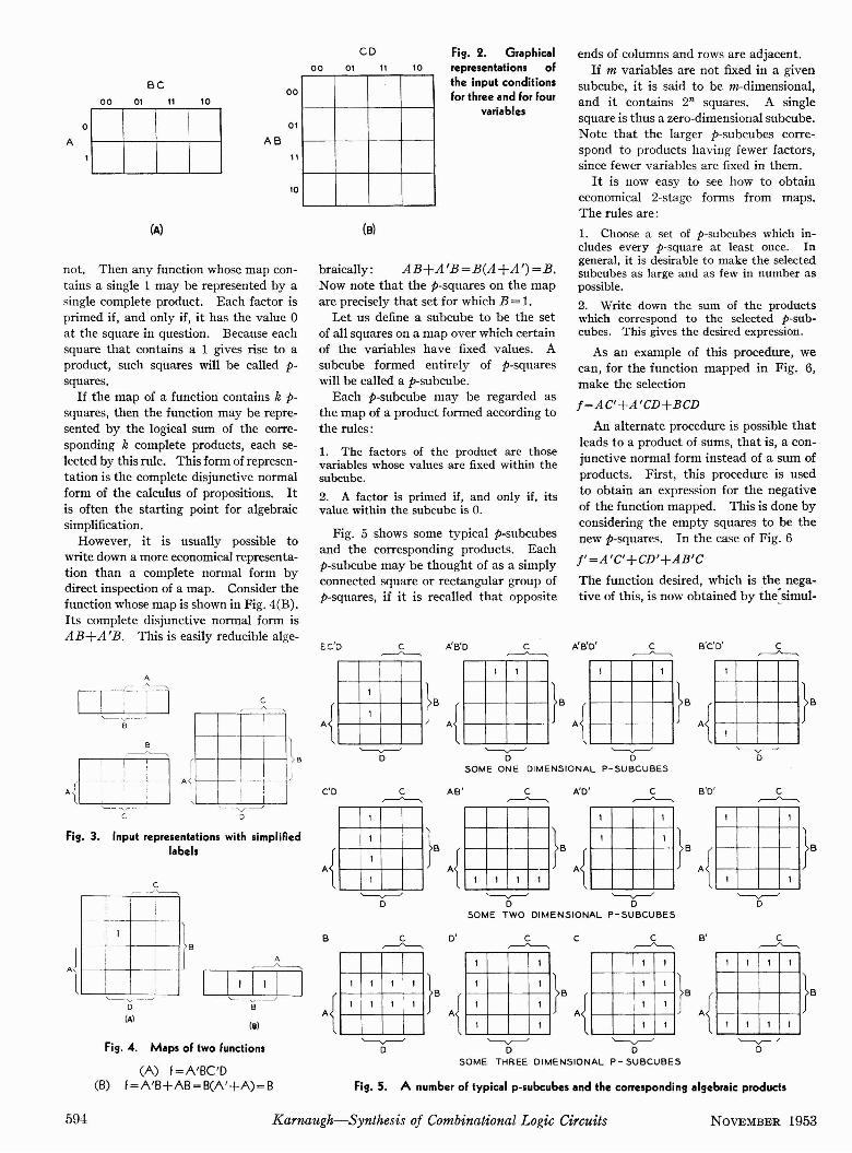
Fig. 3. Input representations with simplifiedlabels
'--v- /D
ends of columns and rows are adjacent.If m variables are not fixed in a given
subcube, it is said to be m-dimensional,and it contains 2n squares. A singlesquare is thus a zero-dimensional subcube.Note that the larger p-subcubes correspond to products having fewer factors,since fewer variables are fixed in them.
It is now easy to see how to obtaineconomical 2-stage forms from maps.The rules are :1. Choose a set of p-subcubes which includes every p-square at least once. Ingeneral, it is desirable to make the selectedsubcubes as large and as few in number aspossible.2. Write down the sum of the productswhich correspond to the selected p-subcubes. This gives the desired expression.
As an example of this procedure, wecan, for the function mapped in Fig . 6,make the selectionj=AC'+A'CD+BCD
An alternate procedure is possible thatleads to a product of sums, that is, a conjunctive normal form instead of a sum ofproducts. First, this procedure is usedto obtain an expression for the negativeof the function mapped. This is done byconsidering the empty squares to be thenew p-squares. In the case of Fig. 6
j'=A'C'+CD'+AB'CThe function desired, which is the negative of this, is now obtained by thesimul-
'---v------' '---v------'D D
SOME ONE DIMENSIONAL P-SUBCUBES
'---v------' '--v--'D D
SOME THREE DIMENSIONAL P- SUBCUBES
Fig. 2. Graphicalrepresentations ofthe input conditionsfor three and for four
variables
10
(e)
CD
'---v------'D
01 11
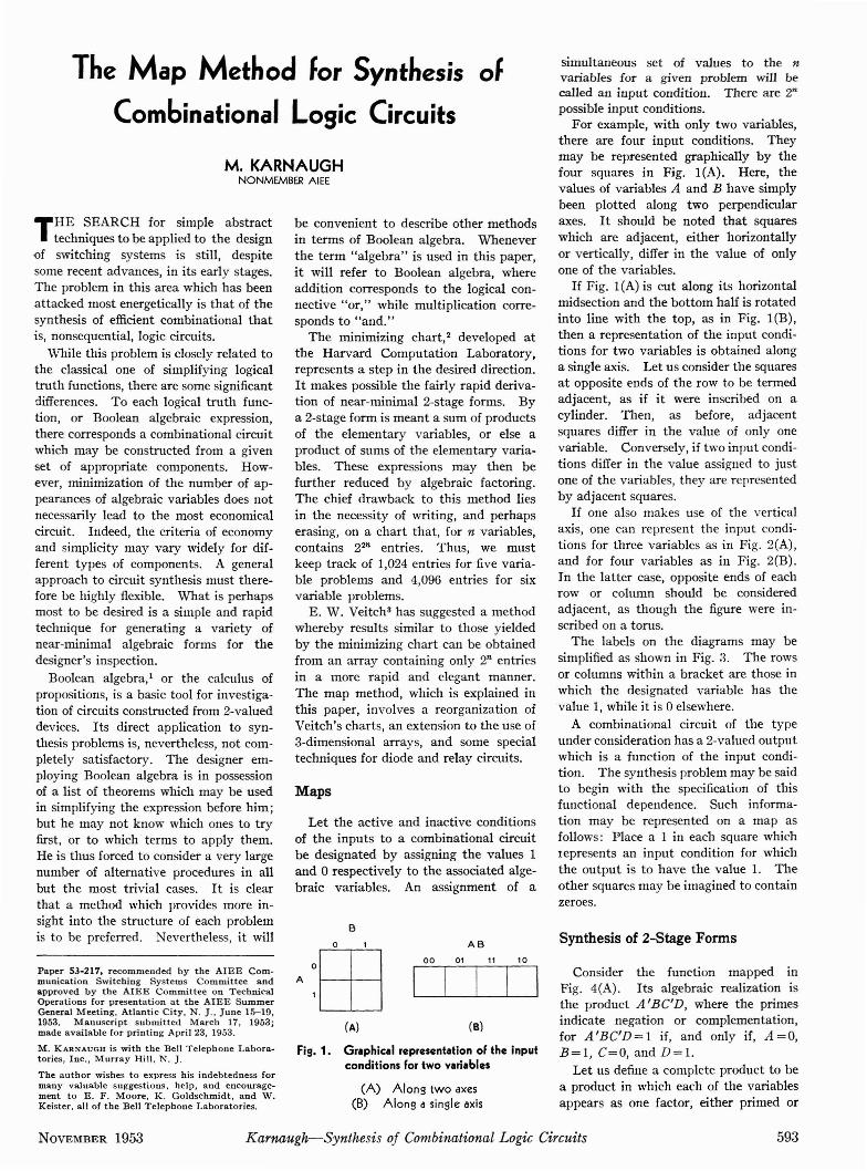
Fig. 5 shows some typical p-subcubesand the corresponding products. Eachp-subcube may be thought of as a simplyconnected square or rectangular group ofp-squares, if it is recalled that opposite
Fig. 5. A number of typical p-subcubes and the corresponding algebraic products
1. The factors of the product are thosevariables whose values are fixed within thesubcube.2. A factor is primed if, and only if, itsvalue within the subcube is O.
braically: AB+A'B=B(A+A')=B.Now note that the p-squares on the mapare precisely that set for which B = 1.
Let us define a subcube to be the setof all squares on a map over which certainof the variables have fixed values. Asubcube formed entirely of p-squareswill be called a p-subcube.
Each p-subcube may be regarded asthe map of a product formed according tothe rules :
00
11
10
01
t!J
00
AB
<r-D
10
~
r- _ -1- ~--+~-
l ! !I
, ~ ---J
(A)
BC01 1100
o
,,-,..
iI
: I~ ~- 1----- .
=fI
~
[T1]1'-,~..-
B
A
(A) f=A'BC'D(B) f=A'B+AB=B(A'+A)=B
Jl
(8)
Fig. 4. Maps of two functions
not. Then any function whose map contains a single 1 may be represented by asingle complete product. Each factor isprimed if, and only if, it has the value 0at the square in question. Because eachsquare that contains a 1 gives rise to aproduct, such squares will be called psquares.
If the map of a function contains k psquares, then the function may be represented by the logical sum of the corresponding k complete products, each selected by this rule. This form of representation is the complete disjunctive normalform of the calculus of propositions. Itis often the starting point for algebraicsimplification.
However, it is usually possible towrite down a more economical representation than a complete normal form bydirect inspection of a map . Consider thefunction whose map is shown in Fig. 4(B).Its complete disjunctive normal form isAB+A'B. This is easily reducible alge-
B-"-----.,
.;\-1H-I""------ -"r-
C
594 Karnaugh-Synthesis of Combinational Logic Circuits NOVEMBER 1953
C D'
}.
r - 1I II 1 1 I
I *:,- 0 Ir II I III '* I
, I 1 ,,I ,
_ _ L _ _ __ JL L
r-- , ..,I I
*I
1 1, II I
~.I _ J
T
I II I , ,I * I 1I IL. J
r r - -==,.I I II 1 I 1 11I I III I IIL -t ~
I II JI 1 II IL .J
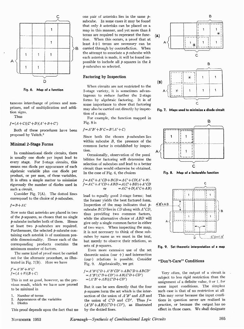
Fig. 9 . Set theoret ic interpretation of a map
" Don't-Care" Conditions
Fig. 8. Map of a factorable function
Very often , th e outp ut of a circuit issub jec t to less rigid restricti on th an theassignme nt of a definite va lue, 0 or I . forsome in put condi tions . The simp lestsuch case is th at of no restriction a t allThis may occur because the input conditions in question never are realized 'inpractice, or because the output ha s noeffect in those cases. We shall designate
Fig. 7. Maps used to minimize a diode circuit
r- - T -r r- - ,,I , I
1 I,I 1 I I I, , ,
-' - - -~L _ -+ __ _ -1 -----) , I I I
A' B'+A B I I I II I I I
) I I I II I I
A{r --- L. L. - , ' ~I II I , , I 1 I,
I , I IIL - - I J • _ _ _ _ L _ _ _J
I , ,I
I
'II'I
I : ,: II ,L . _J L --
r-'D C' D+
Factoring by Inspection
lead to equally good 2-stage forms ; butthe former yields the best factored form.Inspection of the map indicates th at psubcube BCD lies in CD along with A ' CD,thus providing two commo n factors,whil e th e alternative cho ice 'of A BD willgive only a single commo n factor in eitherof two ways. Wh en inspecting th e map,it is not necessary to think of th ese subcubes bv name as we mu st in th e text,bu t merely to observe their relations, assets of p-squares.
Even more exte nsive use of the settheoretic union (our +) and intersection(our ') relations is possibl e. ConsiderFi g. 9. Algebraically , we get
!= A 'B 'C'D+ A 'B'CD'+ABC'D+ABCD'= A 'B'(C'D+CD ' H AB(C'D+CD' )= (.1'B '+AB )(C'D+ CD')
But it can be seen directly that the fourp-squares form the set which is the intersection of the uni on of A'B ' and A B andthe union of C'D and CD'. Thus f=(A 'B'+AB)(C'D+CD') , as illustratedby the dotted lin es.
one pair of aster isks lies in the same psub cube. In some cases it may be foundthat only k asteri sks ca n be placed on amap in this manner , and yet more than kterms are required to represent the func- CA)ti on . When this occurs, a proof that atleast k+1 terms are necessary can becarried through by contradiction. Whenth e a t tem pt to asso cia te a p-subcube witheach as terisk is mad e, it will be found impossible to include all p-squares in the kp-subcubes so selec ted.
Wh en circuits are not restricted to the2-stage variety, it is sometimes advantageous t o reduce fur the r th e 2-stageforms by algebraic factoring. It is ofsome importanc e to sho w that factoringmay also be carried out directly by inspecti on of a map .
For examp le, th e function mapped inFi g. 8 is
!= A 'B '+B' C=B'(A '+C)
Since both the chosen p-subcubes lieswithin subcub e B , th e pre senc e of thecommon factor is established by inspec tion .
Occasionally, observat ion of the possibilities for factoring will det ermine theselection of subcubes and lead to a bettercircuit th an would otherwise be ob ta ined .In th e case of Fig. 6, the choices
! = A C'+.1 'CD+ BCD =.1C'+CD(A'+B)!= A C'+ A'CD+ABD=A (C'+BDHA 'CD
or =AC'+D(A'C+AB )
B
1
1
1 1 1
1 1
~D
tan eous interchan ge of primes and nonprimes, and of multiplication and addition signs .
Thus
Now note that asterisks are placed in twoof th e p-squares, so chosen th at no singlep-subcube includes both of th em. Henceat least two p-subcubes are requ ired .Furthermore, th e selected p-subcube containing each asterisk is of maximum possible dimensionality. Hence eac h of thecorresponding pro ducts contains theminimum number of factors.
The same kind of proof mu st be carri edout for the altern ate procedure, as illustrated in Fi g. i (B) . Here we have
J'= A 'B '+B' C'f= (A +B )(B+C)
This is not as good, however, as th e previous result, which we have now provedto be minimal in
Fig. 6. Map of a function
1. Number of terms2. Appearan ces of the variables3. Diodes
Thi s proof depends upon the fact that no
Minimal 2-Stage Forms
Both of these procedures have beenpro posed by Veitch."
In combinational diode circuits, thereis usually one diode per input lead toeve ry stage. For 2-stage circuits, thismeans one diode per appearance of eachalgebra ic variable plus one diode perproduct, or per sum, of these variables.It is ofte n a simple matter to min imizerigorously th e number of diodes used insuch a circuit.
Consider Fig. 7(A) . The dotted linescorrespond to th e choice of p-subcubes.
! =B+AC
! = (A +C)(c +D )(A '+B+C' )
N OVEMBER 1953 Karnaugh-Synthesis of Combinational Logic Circuits 595

Z 0 T F S245Digit
0 0 . .0 ..0 .. 0 0 0 0 1. .. 11 1. .0 ..0 0. . . 1. .. 1. .. 0 0 02 0 1. . . 0 0 . . 1. .. 0 1. . . 0 03 1. . . 1. . . 0 0 0 1. . . 1. . . 0 04 0 0 1. . . 0 1. . . 0 0 1. . . 05 0 0 0 1. 0 1. . . 0 1. .. 06 1. . . 0 0 1. 0 0 1. . . 1. . . 07 o. . .1. .. O 1. 1. . . 0 0 0 18 1. . . 1. .. 0 1. 0 1. . .0 0 19 O O 1. . . 1. O 0 1. . . 0 1
A prevent any sneak paths between terminals j and k. While disjunctive combinations of this sort are certainly notnew to the relay art," this section is included to show how they may easily berecognized on maps, and hence how theyplaya part in the selection of subcubes.
Note that the paths ABC' and A'BC',which give rise to one of the combinations,differ by only a prime on A. The corresponding subcubes in Fig. 11 are seen tobe related by a simple displacement.The same is true for the other pair of psubcubes.
A little practice will enable the designer to evaluate the various possibilitiesfor factoring and disjunctive combinationby inspection of the maps. It will thenbe a simple task to make a good choiceof p-subcubes.
Table I. SpeciRcations for a Coded DecimalDigit Translator
It is of interest to note that for anygiven function some of the variables ortheir primes may be unnecessary. Thatis, it is possible to find an algebraic representation of the function in which thesevariables, or negated variables, do notappear. Hence the corresponding relay
Unnecessary Contacts
B C I A
S)eo c 1A
~
The map method, inasmuch as it yieldsexpressions in Boolean algebra, can beused to design 2-terminal, series-parallelrelay contact networks, but not bridgetype 2-terminal network s. Hence, many2-terminal contact networks designedby means of the map method will not beminimal in contacts or springs. Thiswill be true, in particular, of the symmetric circuits. 4
However, in the case of complicated,multioutput networks, th e map methodmay be a very effective tool. Supposethat terminal i is a ground, to be connected through networks i ij and i ik to theoutput terminals j and k respectively.The specifications for ft j and i ik. which arenetworks on the contacts of relays A , B,C, D, are mapped in Fig. 11. If eachnet is synthesized separately , thereresults the circuit of Fig. 12(A). InFig. 12(B), it is shown how, with a slightrearrangement, parts of the upper pathsto j and k can be combined, as can partsof the lower paths. This results in asaving of four contacts.
The second circuit is completely equivalent to the first, for the transfers on relay
(
Disjunctive Combination in RelayNets
equal to 0, and the other two equal to 1.The rule for making such choices is as
follows: Assign values to the d's whichenlarge and combine the necessary psubcubes as much as possible but do notmake necessary the selection of any additional subcubes.
The ease with which don 't-cares canbe properly evaluated is one of the majoradvantages shared by the minimizingchart, Veitch chart, and map methods invarying degree.
1 1
, 1
1 1
1 1
d
1 d
1 1 1 Jl d 1 d
obtained by setting the two d's on the right
'---y------/D
~
D
Fig. 11. A i-output problem
Fig. 10. Map of an Incompletely speciRedfunction
such don 't-care conditions by placing thesymbol d in the appropriate squares.
It is usually quite simple to make aneconomical assignment of values to thed-squares by inspection of a map . Sincethese are at the disposal of the designer,it is to his advantage to employ them soas to simplify the resulting circuit.
The best 2-stage form for the functionin Fig. 10 is
!=AC'+BD
A
596 Karnaugh-Synthesis of Combinational Logic Circuits NOVEMBER 1953

5T FZ 0--~ MAKE
- ......--- BREAK
Fig. 15. The flnished translator network
2 I
- '"L~
4
- '" 5
2 1 I L:",1
4 5
I '"5
2 , 5
, I 5
4
2 5X
~~4 5
--=- ~~
~5
, 1 1
d d
d d
1 d d
,d d
, , d d
1 d d
F=
0=
, ,1 d d
1 d d
d d
4~
~5
5 -
1
1 d d
1 d d
, d d
1
, 1 d d
d d
, d d
z=
,{
,{
T=
Fig. 14. Work sheet for synthesis of thetranslator
'-----v---"5
Fig. 1 3. A translato r problem
Fo
relays. From these specifications, oneobtains the five maps in Fig. 13.
At th is point, p-subcubes must be selected, and the desirability kept in mind offactoring and disjunctive combinations.The chosen p-subcubes are listed inTable II, where the numbers in parenthesis indicate the order in which theywere selected. This should be followedon the maps in orde r to see how the termswill combine.
A check on the six d-squares now showsthat each of them has been taken = 1 onat least three of th e maps. Hence therestricti on on unused conditions has beensatisfied, and no cha nges need be madein Table II .
The worksheet on which the network isplanned is shown in Fig. 14. The linesdrawn between terms designate disjunctive combinations or factoring; and thesymbols ad jacent to the lines indicatewhich contacts are shared in each case.A careful comparison of this worksheetwith the resulting network, shown inFig. 15. will enable the reader to understand both.
s
Table II. A List of Selected p-Subeubes
Tz
Suppose it is desired to find a relay contact network to translate coded decimaldigits from a 1-2-4-5 code to 2-out-of-5code. The five outputs will operate therelays Z (zero) , 0 (one), T (two), F (four),and S (seven) . The required translationproperties are listed in Table 1. Theunarithmetic representation for zero isstandard in the 2-out-of-5 code.
The remaining six input conditions forth e 1-2-4-5 relays are unused or don'tcare conditions. However, it is requiredthat none of these conditions results inoperation of zero or two of the five output
Illustrative Example: A RelayTranslator
wherein both the following rules hold :
1. A function may be represented withoutthe appearance of an unprinted variable.say D if. and only if. to each p-square insubcube D there corresponds an adjacentp-square in subcube D' .2. A function may be represented withoutthe appearance of D' if, and only if. to eachp-square in subcube D' there correspondsan adjacent p-square in D.
(1) 4S' (2) 4S (10) 1'2'4 'S' (6) 12 (8) 12'S(3) 12 ·S· (4) 12·S (12) 2S (7) 12 'S' (13) 4S'(S) 1' 2 (11) 2S' (14) -is (9) 1'2·4·S ( IS ) 1' 2'4
2
T £.' 2' 51' 2'4
2S 45
<, 2 \ d4'~'~25 4
45
(45
5 12'5
£ .Q" 2-------=------ 12
,(,ts " 2'4 55 45' ' 2' 5'
contact network will not contain makecontacts, or break -contacts, on some of therelays.
For examp le, the functions in Fig. 11are shown on four -variable maps, butthey may be realized in terms of onlythree variables, as in Fig. 12. Neither Vnor V ' is necessary.
In this case, it can be seen at a glancethat the patterns appearing in the V andD' subcubes in both maps are identical.Therefore the output is independent ofthe value assigned to V . This is a case
NOVEMBER 1953 Karnaugh-Synthesis of Combinational Logic Circuits 597

Three-Dimensional Maps
Up to this point , we have discussedfunctions of no more than four variables.If it is desir ed to increase the number ofvariables on a map, two possibilities suggest themselves:
1. Increase the number of variablesplotted on each axis.2. Use three mutually perpendicular axesinstead of two.
Both methods are feasible. Ifmethod 2 is employed, th en for (even) 11
variables, we will have n/ 2 on each axis.This means an array of 2n12 by 2n/2squares. However, with more th an twovariables on an axis, the definition ofadjacence must be extended rather tenuously and subcubes become more difficult to recognize. This scheme is likethe one originally suggested by Veitch ."
We have chosen method 2, which allowsa 50-per-cent increase in the number ofvariables without any extension of therules. Thus, for six variables, the methods we have described still apply, butin three dimensions.
A suitable framework is shown in Fi g.16. It consists of four 6-inch squareplexiglass sheets supported at l- I/ 2-inch
intervals by rods of the same material.The rods and sheets are glued together.The author has been told that the 3dimensional ticktacktoe boards sold atsome toy shops under various names aresat isfactory .
Each sh eet is ruled at J-I/2-inch intervals parallel to both pairs of edges. Thuswe ha ve a 4-by-4 array of squares onevery sheet . The plexiglass frameworkenables us to do away with the writingand erasing which would be necessarywhen dealing with similar problems by
Fig. 16. The cube: a 3-dimensional plasticframework for maps
other methods . In using it, we employmovable markers, such as 7I S-inch plasticroulette chips. The following scheme issuggested:1. Mark all p·squares with white chips.2. Mark all d-squares with black chips.3. As subcubes are selected, mark eachone with a set of distinctively colored chips .
Chips of eight or nine different colorsare usually sufficient to make all theselected subcubes easily distinguishable.The corresponding products are thenfound by means of labels on the edges ofthe plastic cube.
One satisfactory labeling scheme isshown in Fig. 16. The two bottom planesare A, while the middle two are B. Thevariables C, D, E, and F are arr anged oneach plane as on the top, each letter serving to label two rows or columns. Opposite ends of an y row, column, or verticalon the cube must be considered adjacent.Then every subcube may be thought of asa rectangular parallelepiped with edges 1,2, or 4 units long. For multioutput problems, it is best to have a set of cubes, oneper output.
The extension to seven variables is
probably best accomplished by placingtwo cubes side by side. Correspondingsquares in the tw o cubes must be considered adjacent when looking for psubcubes. Ei ght variables can be handled with a set of four cubes, and ninevariables require eight cubes. In thelatter case, it is convenient to makethem so as to stack easily into two layersof four each. Beyond nine variables, themental gymnast ics required for synthesiswill, in general, be formidable . Othermethods are even more limited in thisrespect. Outstanding exceptions to thislimitation are the symmetric and positi onal circuits, discussed by Keister,Ritchie, and Washburn.!
Conclusions
Employment of the map method seemsto be profitable when nontrivial problemsin combinational circuit synthesis arise.Its most important advantages appear tobe flexibility and speed . Further, ifsuch problems ar ise frequently, it isad vantageous to have a method, such asthis, which can be learned and used effectively in a shor t time by designers newto the field.
References
1. TH E D ESIGN OF SWITCffiNG CIRCUITS (bo ok).William Keister, A. E . Ritchie, S . H. Washburn.D . Van N ostrand C ompany, New York, N . Y.,1951, chap. 5.
2. SYNTHESIS OF ELECTRONIC C OMPUTING ANDCONTROL CIRCUITS (bo ok) , Staff of the HarvardComputation Laboratory. Harvard UniversityPress, Cambrid ge , Mass., 1951, chap. 5.
3 . A CHART M ETHOD FOR SIMPLIFYING TRUTHFUNCTlONS, E. W . Veitch. Proceedings, Association for Computing Machinery, Pittsburgh, Pa. ,May 2, 3, 1952 .
4. See reference I , pp. 55-64.
5. See reference I, pp. 295-297.
- - -------- ---+- - - - - - --------
Discussion
S. H. Caldwell (Massachusctts Institute ofTechnology, Cambridge, Mass.): WhenShannon published his classic paper onanalyzing relay and switching circuits; ' theengineer was given a powerful method forthe solut ion of many problems in the fieldof switching circuit s. Unfortunately. whenone att empted to use th e method, th erearose a peculiar sort of frustrati on. Given acircuit which had been designed by th emethods of trial and error prevalent at th etim e, it was readily possible to usc Shannon's techn iques to investigat e alterna tiveforms. In particular, th e switching algebracould he used directly for th e simplificat ionof cont act networks. But th e situation wasdifferent with respect to the synthesis of anetwork (unl ess it could be described by asymmetric funct ion). In th e general case.
it was necessary to resort to a word statement of the requir ed circuit charact erist icsand then convert thi s to an algebra ic statement.
For simple problems, and especially thosewhich involv ed a small number of variables.no difficulty was encountered, but becauseof their very simplicity such probl ems rarelyneeded th e algebra ic approach. When problems of any magnitude were at tempted, themethod brok e down both because of thedifficulty of writing word statements andbecause of th e difficulty of convert ing bulkyword st ate ments into algebraic expressions.
These difficulti es were resolved by theadaptat ion of the logical truth table into th efamiliar tabl e of combinations (see ref. I ofthe paper ). This mechanism enabled th edesigner to state his requirement s in anorderly manner, and gave him a systematicmeans for checking the completeness of hisreasoning . Moreover. the transition from
the table of combinations to an equivalentalgebraic state ment became almost a matterof routine, depending on individual preference for simplifying the algebraic expressionby inspection of the table or by algebraicmanipulation.
The arrays described by Veitch (see ref. 3of the pap er) and by Mr. Karnaugh represent further development of the table ofcombin ations into forms which are morecompact. and which also have the propertyof making more evident th e way s in whichthe algebra ic expression of a switching funct ion can be simplified. Of course. the endresult desired in all cases is a minimizationof th e required circuit . what ever we meanby the word " minimizat ion."
The problem of manipulating functionsof many variables is much like th e problemthe physicist had in his development ofmathematical models of atomic structure.Over a period of years he succeeded in
598 Karnaugh-Synthesis of Combinational Logic Circuits NOVEMBER 1953

A. M. INTRATORASSOCIATE MEMBER AlEE
The Use of Steel Sheet For the
Construction of Shielded Rooms
getting better and better mathematicalsolutions for the hydrogen atom, but noneof his methods really worked when he triedto add just one more electron. Similarly,in these various methods for reducingswitching functions to minimal forms weseem to be producing better and betterways for reducing functions of four variables,but we are still rather unhappy about fiveand six variables. The author's plasticcube for the treatment of six variables is aningenious extension of his four-variablearray, and it certainly has the reductionproperties he ascribes to it . It does not ,however , have the neatness of display whichis a feature of the plane map; groupings ofvariables are not as immediately evident,and alternative groupings are even lessapparent.
Mr . Karnaugh rightly points out that thesearch represented by this paper is in itsearly stages. It should be added that thenecd for better methods for handling theproblem in more than four variables will become acute, and it is a problem worthy ofthe best thinking. Recent developments inthe synthesis of sequential circuits show thatthe end result of a sequential synthesis is acombinational problem. It is a multiple output problem in many variables, and hasramifications which will tax the best effortsof the circuit designer. Among the possibilities for meeting this problem is that ofmechanizing the process involved in themap method.
LOW-LE VE L electronic or electricalmeasurements are particularly sus
ceptible to errors introduced by externalelectromagnetic influences. The coupling of spurious electromagnetic energyinto a measuring system not only mayresult in the receipt of false informationbut also can sometimes cause the complete masking of the desired data aswell. For these reasons, many low-levelmeasurements, such as the determinationof crystal characteristics, filter insertionloss, noise measurements, and the like,must be made in a location as free aspossible from such interference. In alaboratory, such isolation from interference is usually achieved by completelyenclosing an area in copper or bronzescreening. By shielding off a region relatively free of external interference in thisway, a working area is provided withinwhich sensitive electronic measurementscan be made.
Incidentally, I am not impressed by thedrawbacks attributed to the Harvard Computation Laboratory minimizing chart.The large number of entries involved is nodrawback in these days of cheap duplicationprocesses. Keeping track of the entries isreally a simple routine. In using the chartfor the realization of six-variable functionswith don't-care conditions, I find that onerarely has to complete the vertical ruling ofthe entire chart because the required conditions are usually satisfied with terms at theleft-hand side of the chart. In some casesone finds a condition which is satisfied byonly one possible minimal term, where theacceptance of that term in turn specifiesthe nature of one or more don't-care conditions. Of course, the six-variable cube inherently contains the same information, butit is doubtful that its display gives the designer quite as much immediate guidance ashe gets from the minimizing chart.
REFERENCE
1. A SYMBOLIC ANAl YSIS OF RELAY AND SWITCHING CIRCUITS, Claude E Shannon. Al EE Transactions, vol. 57 . 1938, pp 713 -23.
M. Karnaugh: In view of Professor Caldwell's remarks about mechanization, itappears to be desirable to restate the reasonsfor presenting this paper.
The map method, in its present form, islikely to be useful in two ways: as a peda-
Certain instrumentation requires amuch higher degree of freedom fromextraneous influences than can be obtained in screened enclosures. A reduction in the shielding efficiency of screenedbooths occurs at the lower frequencies because of practical limitations in wire sizeand at higher frequencies because thewave lengths begin to approach the dimensions of the mesh openings. Fig. Ishows a typical attenuation curve of ascreened room. Because sheet metalpresents neither of these difficulties, it isoften used instead of screening, to enclosethose areas in which a high degree ofshielding is required .
Copper sheet has ordinarily been usedfor this purpose, although copper-cladsteel has been used in some cases. Suchrooms are usually double-walled; theinner and outer sheet-metal walls arespaced about 4 inches apart and are insulated from each other except at the point
gogic device, for the introduction of ideasabout logic circuits and their synthesis, andalso as a desk-top aid to the working engineer .
In making full use of the human facultyfor recognizing geometric patterns at aglance, the map method supplies a numberof short cuts to synthesis that are not aseasily found by other methods. On theother hand, the development of machinewhich can recognize such relationships hasonly begun. If one mechanizes the mapmethod in a more conventional way, using arepetitive scanning technique, then the result is similar to a mechanization of theHarvard minimizing charts and no specialadvantages are expected.
The minimizing charts, which representone of the first significant advances overpurely algebraic manipulation, have proventheir usefulness in practice and will undoubtedly do so even more convincinglywhen machines are programmed to workalong the same lines . However, it has beenthe author's experience that maps presentthe specifications for a logic circuit in a formmore easily used by the human operator.Here, habit and taste enter the picture andit would be unwise to dwell on this point.
For those who are relatively new to theproblem under discussion, it is suggestedthat a number of problems be worked byboth methods. It is of interest to see howthey are related, and each will throw somelight on the operation of the other.
where the power line enters the room.Ordinarily the walls are hung upon a kilndried, wax-impregnated wood frame andall seams and mounting nails or bolts arecompletely soldered over to reduce thepossibility of energy leakageinto the room.Special seals are used to insure continuous metal-to-metal contact aroundthe periphery of the door. Air is introduced through "waveguide below cutoff"vents, the cutoff frequency being determined by the expected top operating frequencies in the room. All power linesentering the room are filtered.
These rooms are very expensive, havingranged in cost from about $10,000 forsmall rooms to $100,000 for much larger
Paper 53-197, recommended by the AlEE Instruments and Measurements Committee and approvedby the AlEE Committee on Technical Operationsfor presentation at the AlEE Summer GeneralMeeting, Atlantic City, N . J .• June 15-19, 1953.Manuscript submitted February 11, 1953; madeavailable for printing March 3D, 1953.
A. M . INTRATOR was formerly with the UnitedStates Naval Civil Engineering: Research and Evaluation Laboratory, Port Hueneme. Calif. . and isnow with the General Electric Company, Syracuse,N .Y .
The author wishes to express his appreciation tothe members of the st a ff of the Stanford ResearchInstitute Engineering Division, who performedmost of the work described in this paper; to Dr.D . L . Benedict for his efforts in directing theStanford Research Institute program; and toDr. C . R. Freberg, formerly of the United StatesNaval Civil Engineering Research and EvaluationLaboratory, for the suggestions which Jed to thisinvestigation.
NOVEMBER 1953 Intrator-Steel Sheet for Construction of Shielded Rooms 599