Embed Size (px)
Citation preview

MITSUBISHI ELECTRIC
MITSUBISHI ELECTRIC INDUSTRIAL AUTOMATION
GOT1000
GT1020/GT1030 to FR-A700 Inverter
Start-up Guide
Art.-Nr.: xxxxxx12 11 2008Version A

GOT1000 I
About this Manual
The texts, illustrations, diagrams and examples in this manual are only intended as aids to helpexplain the functioning, operation, use and programming of the GOT1000 terminals in combi-nation with an FR-A700 Inverter.
If you have any questions regarding the installation and operation of the hardware described inthis manual, please do not hesitate to contact your sales office or one of your Mitsubishi distri-bution partners.
You can also obtain information and answers to frequently asked questions from our Mitsubishiwebsite under www.mitsubishi-automation.com.
No part of this manual may be reproduced, copied, stored in any kind of information retrieval sy-stem or distributed without the prior express written consent of MITSUBISHI ELECTRIC.
MITSUBISHI ELECTRIC reserves the right to change the specifications of its products and/orthe contents of this manual at any time and without prior notice.
© Version A November 2008
Manual References:
Refer to the following manuals for more detailed explanations. For any further questions, pleasecontact your local Mitsubishi Product Provider.
● GOT1000 Series Connection Manual 3/3 (SH(NA)-080532ENG), Sections 37.1 to 37.6
● Inverter FR-A 700 Instruction Manual (Applied) (IB(NA)-0600257ENG-B)
ECAUTION:
Do not attempt to install, operate, maintain or inspect the grafical operator terminal orthe inverter until you have read through the correrponding instruction manual care-fully and can use the equipment correctly. Do not use the inverter until you have a fullknowledge of the equipment, safety information and instructions.
ECAUTION:
This Start-up Guide includes a brief summary of the main specifications of theGOT1000 graphic operation terminals and the FR-A700 series of inverters, whichshould be sufficient to enable experienced users to install and configure the units.For further information on the operation terminals and the inverters please refer to theabove mentioned manuals.
Please observe also the safety precautions given in the manuals mentioned above.

II
Table of Contents
GOT1000 III
Table of Contents
1 Overview . . . . . . . . . . . . . . . . . . . . . . . . . . . . . . . . . . . . . . . . . . . . . . . . . . . . . . . . . . . .1
2 Hardware Introduction. . . . . . . . . . . . . . . . . . . . . . . . . . . . . . . . . . . . . . . . . . . . . . . . .1
3 Cabling . . . . . . . . . . . . . . . . . . . . . . . . . . . . . . . . . . . . . . . . . . . . . . . . . . . . . . . . . . . . .2
3.1 GOT and Inverter Wiring Diagrams . . . . . . . . . . . . . . . . . . . . . . . . . . . . . . . . .4
3.2 GOT Terminals . . . . . . . . . . . . . . . . . . . . . . . . . . . . . . . . . . . . . . . . . . . . . . . . .6
3.3 Programming Cables . . . . . . . . . . . . . . . . . . . . . . . . . . . . . . . . . . . . . . . . . . . .6
4 GT Designer 2 . . . . . . . . . . . . . . . . . . . . . . . . . . . . . . . . . . . . . . . . . . . . . . . . . . . . . . .7
5 Inverter Settings. . . . . . . . . . . . . . . . . . . . . . . . . . . . . . . . . . . . . . . . . . . . . . . . . . . . . .9
6 Station Setting . . . . . . . . . . . . . . . . . . . . . . . . . . . . . . . . . . . . . . . . . . . . . . . . . . . . . .10
6.1 Indirect Specification. . . . . . . . . . . . . . . . . . . . . . . . . . . . . . . . . . . . . . . . . . . .10
7 Confirm Communication . . . . . . . . . . . . . . . . . . . . . . . . . . . . . . . . . . . . . . . . . . . . . .11

Overview Start-up Guide
GOT1000 1
1 Overview
This document provides a simple guide to setting up the GT1020 or GT1030 Graphic OperationTerminal (GOT) hardware and firmware for use with an FR-A 700 Inverter.
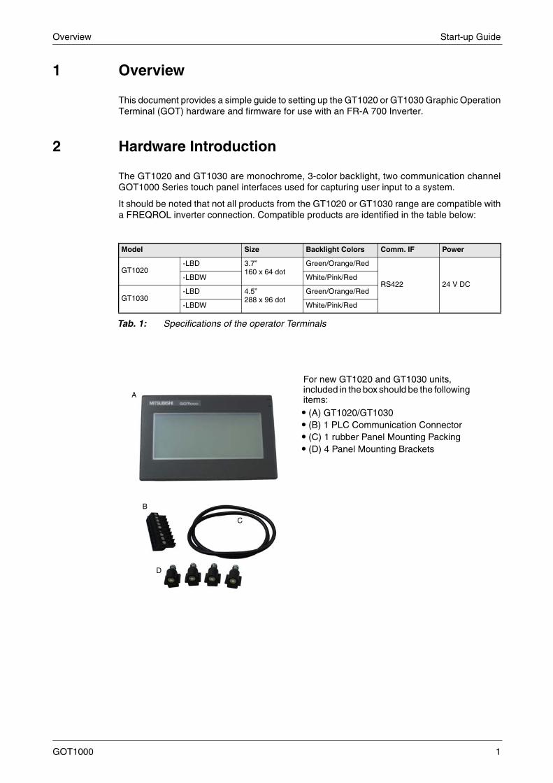
2 Hardware Introduction
The GT1020 and GT1030 are monochrome, 3-color backlight, two communication channelGOT1000 Series touch panel interfaces used for capturing user input to a system.
It should be noted that not all products from the GT1020 or GT1030 range are compatible witha FREQROL inverter connection. Compatible products are identified in the table below:
Model Size Backlight Colors Comm. IF Power
GT1020-LBD 3.7”
160 x 64 dotGreen/Orange/Red
RS422 24 V DC-LBDW White/Pink/Red
GT1030-LBD 4.5”
288 x 96 dotGreen/Orange/Red
-LBDW White/Pink/Red
Tab. 1: Specifications of the operator Terminals
For new GT1020 and GT1030 units, included in the box should be the following items:
� (A) GT1020/GT1030� (B) 1 PLC Communication Connector� (C) 1 rubber Panel Mounting Packing� (D) 4 Panel Mounting Brackets
A
B
C
D
Start-up Guide Cabling
2
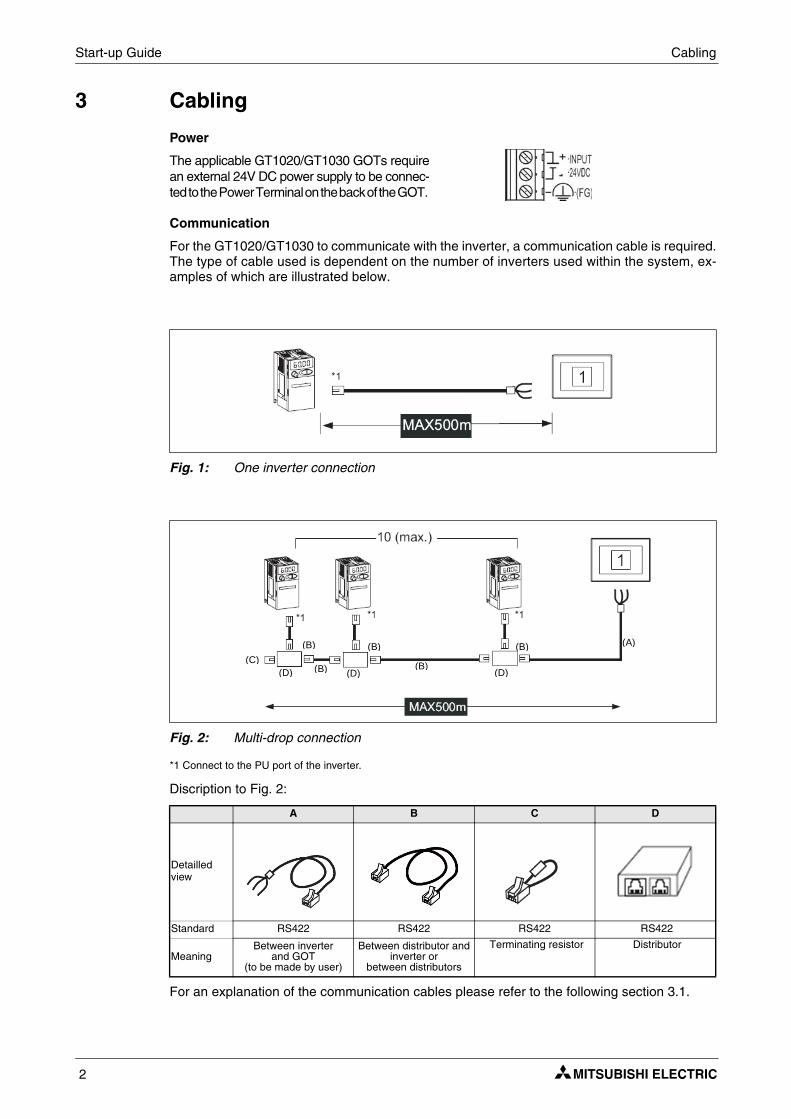
3 Cabling
Communication
For the GT1020/GT1030 to communicate with the inverter, a communication cable is required.The type of cable used is dependent on the number of inverters used within the system, ex-amples of which are illustrated below.
*1 Connect to the PU port of the inverter.
Discription to Fig. 2:
For an explanation of the communication cables please refer to the following section 3.1.
Power
The applicable GT1020/GT1030 GOTs requirean external 24V DC power supply to be connec-ted to the Power Terminal on the back of the GOT.
Fig. 1: One inverter connection
Fig. 2: Multi-drop connection
A B C D
Detailled view
Standard RS422 RS422 RS422 RS422
MeaningBetween inverter
and GOT(to be made by user)
Between distributor and inverter or
between distributors
Terminating resistor Distributor
(A) (B)
(B)
(B)(B) (C)
(B)(D) (D) (D)
Cabling Start-up Guide
GOT1000 3
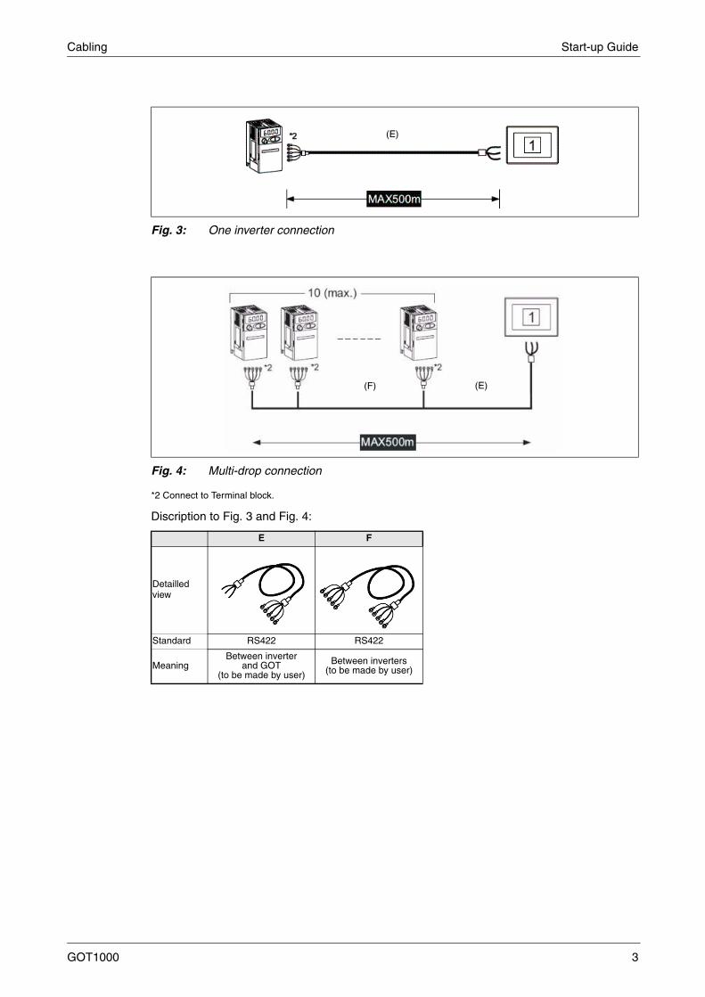
*2 Connect to Terminal block.
Discription to Fig. 3 and Fig. 4:
Fig. 3: One inverter connection
Fig. 4: Multi-drop connection
E F
Detailled view
Standard RS422 RS422
MeaningBetween inverter
and GOT(to be made by user)
Between inverters(to be made by user)
(E)
(F) (E)
Start-up Guide Cabling
4
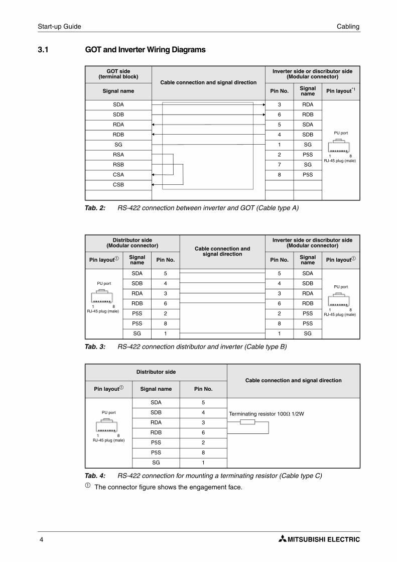
3.1 GOT and Inverter Wiring Diagrams
� The connector figure shows the engagement face.
GOT side(terminal block)
Cable connection and signal direction
Inverter side or discributor side (Modular connector)
Signal name Pin No. Signal name Pin layout*1
SDA 3 RDA
PU port
1 8RJ-45 plug (male)
SDB 6 RDB
RDA 5 SDA
RDB 4 SDB
SG 1 SG
RSA 2 P5S
RSB 7 SG
CSA 8 P5S
CSB
Tab. 2: RS-422 connection between inverter and GOT (Cable type A)
Distributor side(Modular connector) Cable connection and
signal direction
Inverter side or discributor side (Modular connector)
Pin layout� Signal name Pin No. Pin No. Signal
name Pin layout�
PU port
1 8RJ-45 plug (male)
SDA 5 5 SDA
PU port
1 8RJ-45 plug (male)
SDB 4 4 SDB
RDA 3 3 RDA
RDB 6 6 RDB
P5S 2 2 P5S
P5S 8 8 P5S
SG 1 1 SG
Tab. 3: RS-422 connection distributor and inverter (Cable type B)
Distributor side
Cable connection and signal direction
Pin layout� Signal name Pin No.
PU port
1 8RJ-45 plug (male)
SDA 5
Terminating resistor 100� 1/2WSDB 4
RDA 3
RDB 6
P5S 2
P5S 8
SG 1
Tab. 4: RS-422 connection for mounting a terminating resistor (Cable type C)
Cabling Start-up Guide
GOT1000 5
GOT side(terminal block)
Cable connection and signal direction
Inverter side RS485 terminal block (built into the inverter)
Signal name Terminal Name Terminal block name
SDA RDA1 (RXD+)RXD
SDB RDB1 (RXD1–)
RDA SDA1 (TXD1+)TXD
RDB SDB1 (TXD1–)
SG SG (GND) VCC
RSA
RSB
CSA
CSB
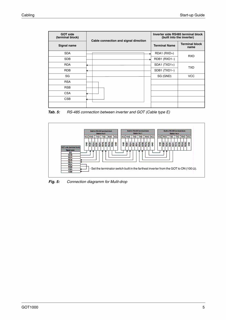
Tab. 5: RS-485 connection between inverter and GOT (Cable type E)
Fig. 5: Connection diagramm for Mulit-drop
- Set the terminator switch built in the farthest inverter from the GOT to ON (100 ).

Start-up Guide Cabling
6
3.2 GOT Terminals
The GT1020/GT1030 is fitted with screw terminals, use a small flathead screwdriver to securethe wires within the PLC Communication Connector.
3.3 Programming Cables
The GT1020 and GT1030 come pre-installed with an OS and FX communication driver, but wi-thout any project data. To download a project from a PC running GT Designer2 to the GOT, aprogramming cable is required that connects to the RS-232C 6-pin Mini-DIN port on the back ofthe GOT. It is recommended to use a shielded USB A-type to Mini-B type cable with a ferrite corepaired with the GT10-RS2TUSB-5S, but any RS-232C programming cable for the Q-Series willalso work fine. A diagram of both is shown below.
Fig. 6: Terminal points in detail
Fig. 7: Connection diagram
NOTE Note that using the GT10-RS2TUSB-5S will require a virtual USB COM port driver to beinstalled on the PC. The COM port number can be automatically or manually assigned sothat it does not overlap with the existing COM port numbers assigned on that PC. Whenusing a Q-Series programming cable, the COM port number already assigned to the RS-232C interface of the PC will have to be checked.
USB + GT10-RS2TUSB-5S
QC30R2 (RS-232C)
PC
or GOT
GT Designer 2 Start-up Guide
GOT1000 7
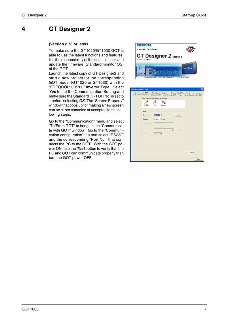
4 GT Designer 2
(Version 2.73 or later)
To make sure the GT1020/GT1030 GOT isable to use the latest functions and features,it is the responsibility of the user to check andupdate the firmware (Standard monitor OS)of the GOT.Launch the latest copy of GT Designer2 andstart a new project for the correspondingGOT model (GT1020 or GT1030) with the“FREQROL500/700” Inverter Type. SelectYes to set the Communication Setting andmake sure the Standard I/F-1 CH No. is set to1 before selecting OK. The “Screen Property”window that pops up for making a new screencan be either canceled or accepted for the fol-lowing steps.
Go to the “Communication” menu and select“To/From GOT” to bring up the “Communica-te with GOT” window. Go to the “Communi-cation configuration” tab and select “RS232”and the corresponding “Port No.” that con-nects the PC to the GOT. With the GOT po-wer ON, use the Test button to verify that thePC and GOT can communicate properly thenturn the GOT power OFF.
Start-up Guide GT Designer 2
8
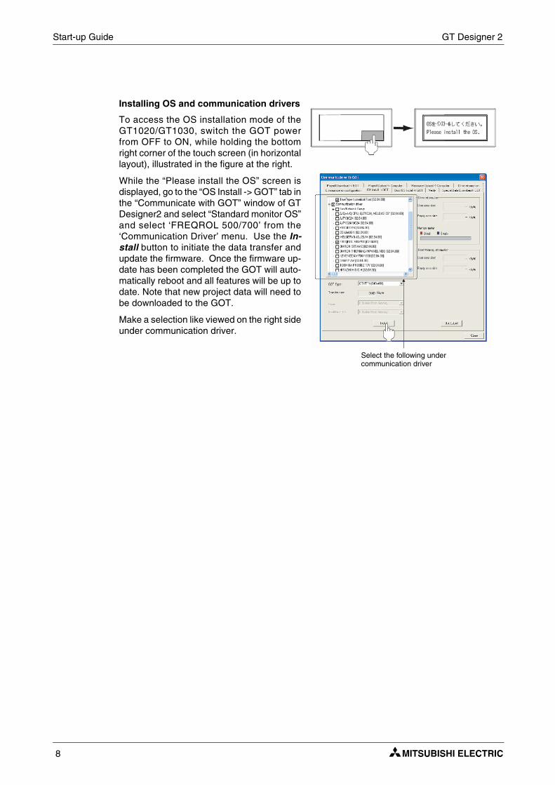
Installing OS and communication drivers
To access the OS installation mode of theGT1020/GT1030, switch the GOT powerfrom OFF to ON, while holding the bottomright corner of the touch screen (in horizontallayout), illustrated in the figure at the right.
While the “Please install the OS” screen isdisplayed, go to the “OS Install -> GOT” tab inthe “Communicate with GOT” window of GTDesigner2 and select “Standard monitor OS”and select ‘FREQROL 500/700’ from the‘Communication Driver’ menu. Use the In-stall button to initiate the data transfer andupdate the firmware. Once the firmware up-date has been completed the GOT will auto-matically reboot and all features will be up todate. Note that new project data will need tobe downloaded to the GOT.
Make a selection like viewed on the right sideunder communication driver.
Select the following under communication driver
Inverter Settings Start-up Guide
GOT1000 9
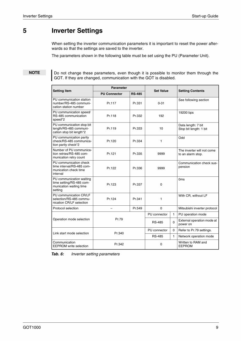
5 Inverter Settings
When setting the inverter communication parameters it is important to reset the power after-wards so that the settings are saved to the inverter.
The parameters shown in the following table must be set using the PU (Parameter Unit).
NOTE Do not change these parameters, even though it is possible to monitor them through theGOT. If they are changed, communication with the GOT is disabled.
Setting itemParameter
Set Value Setting ContentsPU Connector RS-485
PU communication station number/RS-485 communi-cation station number
Pr.117 Pr.331 0-31See following section
PU communication speed/RS-485 communication speed*2
Pr.118 Pr.332 19219200 bps
PU communication stop bit length/RS-485 communi-cation stop bit length*2
Pr.119 Pr.333 10Data length: 7 bitStop bit length: 1 bit
PU communication parity check/RS-485 communica-tion parity check*2
Pr.120 Pr.334 1Odd
Number of PU communica-tion retries/RS-485 com-munication retry count
Pr.121 Pr.335 9999The inverter will not come to an alarm stop.
PU communication check time interval/RS-485 com-munication check time interval
Pr.122 Pr.336 9999
Communication check sus-pension
PU communication waiting time setting/RS-485 com-munication waiting time setting
Pr.123 Pr.337 0
0ms
PU communication CR/LF selection/RS-485 commu-nication CR/LF selection
Pr.124 Pr.341 1With CR, without LF
Protocol selection – Pr.549 0 Mitsubishi inverter protocol
Operation mode selection Pr.79
PU connector 1 PU operation mode
RS-485 0 External operation mode at power on
Link start mode selection Pr.340PU connector 0 Refer to Pr.79 settings.
RS-485 1 Network operation mode
Communication EEPROM write selection Pr.342 0 Written to RAM and
EEPROM
Tab. 6: Inverter setting parameters
Start-up Guide Station Setting
10
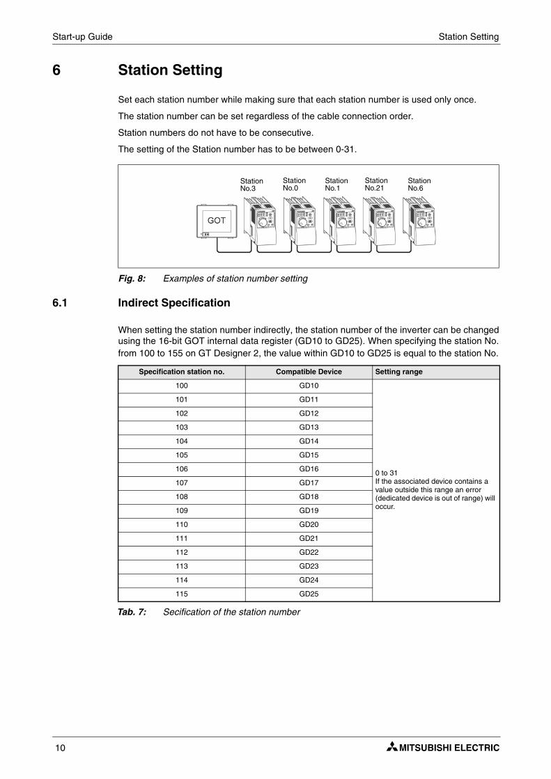
6 Station Setting
Set each station number while making sure that each station number is used only once.
The station number can be set regardless of the cable connection order.
Station numbers do not have to be consecutive.
The setting of the Station number has to be between 0-31.
6.1 Indirect Specification
When setting the station number indirectly, the station number of the inverter can be changedusing the 16-bit GOT internal data register (GD10 to GD25). When specifying the station No.from 100 to 155 on GT Designer 2, the value within GD10 to GD25 is equal to the station No.
Tab. 7: Secification of the station number
Fig. 8: Examples of station number setting
Specification station no. Compatible Device Setting range
100 GD10
0 to 31If the associated device contains a value outside this range an error (dedicated device is out of range) will occur.
101 GD11
102 GD12
103 GD13
104 GD14
105 GD15
106 GD16
107 GD17
108 GD18
109 GD19
110 GD20
111 GD21
112 GD22
113 GD23
114 GD24
115 GD25
StationNo.3
StationNo.0
StationNo.1
StationNo.21
StationNo.6
Confirm Communication Start-up Guide
GOT1000 11
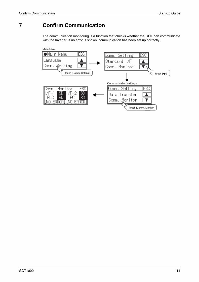
7 Confirm Communication
The communication monitoring is a function that checks whether the GOT can communicatewith the Inverter. If no error is shown, communication has been set up correctly.

Start-up Guide Confirm Communication
12

HEADQUARTERS
EUROPEMITSUBISHI ELECTRIC EUROPE B.V.German BranchGothaer Straße 8D-40880 RatingenPhone: +49 (0)2102 / 486-0Fax: +49 (0)2102 / 486-1120
CZECH REPUBLICMITSUBISHI ELECTRIC EUROPE B.V.Czech BranchRadlicka 714/113 aCZ-158 00 Praha 5Phone: +420 251 551 470Fax: +420-251-551-471
FRANCEMITSUBISHI ELECTRIC EUROPE B.V.French Branch25, Boulevard des BouvetsF-92741 Nanterre CedexPhone:+33 (0)1 / 55 68 55 68Fax: +33 (0)1 / 55 68 57 57
IRELANDMITSUBISHI ELECTRIC EUROPE B.V.Irish BranchWestgate Business Park, BallymountIRL-Dublin 24Phone: +353 (0)1 4198800Fax: +353 (0)1 4198890
ITALYMITSUBISHI ELECTRIC EUROPE B.V.Italian BranchViale Colleoni 7I-20041 Agrate Brianza (MI)Phone: +39 039 / 60 53 1Fax: +39 039 / 60 53 312
SPAINMITSUBISHI ELECTRIC EUROPE B.V.Spanish BranchCarretera de Rubí 76-80E-08190 Sant Cugat del Vallés (Barcelona)Phone: 902 131121 // +34 935653131Fax: +34 935891579
UKMITSUBISHI ELECTRIC EUROPE B.V.UK BranchTravellers LaneUK-Hatfield, Herts. AL10 8XBPhone: +44 (0)1707 / 27 61 00Fax: +44 (0)1707 / 27 86 95
JAPANMITSUBISHI ELECTRIC CORPORATIONOffice Tower “Z” 14 F8-12,1 chome, Harumi Chuo-KuTokyo 104-6212Phone: +81 3 622 160 60Fax: +81 3 622 160 75
USAMITSUBISHI ELECTRIC AUTOMATION, Inc.500 Corporate Woods ParkwayVernon Hills, IL 60061Phone: +1 847 478 21 00Fax: +1 847 478 22 53
EUROPEAN REPRESENTATIVES
AUSTRIAGEVAWiener Straße 89AT-2500 BadenPhone: +43 (0)2252 / 85 55 20Fax: +43 (0)2252 / 488 60
BELARUSTEHNIKONOktyabrskaya 16/5, Off. 703-711BY-220030 MinskPhone: +375 (0)17 / 210 46 26Fax: +375 (0)17 / 210 46 26
BELGIUMKoning & Hartman b.v.Woluwelaan 31BE-1800 VilvoordePhone: +32 (0)2 / 257 02 40Fax: +32 (0)2 / 257 02 49
BULGARIAAKHNATON4 Andrej Ljapchev Blvd. Pb 21BG-1756 SofiaPhone: +359 (0)2 / 817 6004Fax: +359 (0)2 / 97 44 06 1
CROATIAINEA CR d.o.o.Losinjska 4 aHR-10000 ZagrebPhone: +385 (0)1 / 36 940 - 01/ -02/ -03Fax: +385 (0)1 / 36 940 - 03
CZECH REPUBLICAutoCont C.S., s.r.o.Technologicka 374/6CZ-708 00 Ostrava PustkovecPhone: +420 (0)59 / 5691 150Fax: +420 (0)59 / 5691 199
CZECH REPUBLICB:TECH, a.s.U Borove 69CZ-58001 Havlickuv BrodPhone: +420 (0)569 777 777Fax: +420 (0)569-777 778
DENMARKBeijer Electronics A/SLykkegårdsvej 17, 1.DK-4000 RoskildePhone: +45 (0)46/ 75 76 66Fax: +45 (0)46 / 75 56 26
ESTONIABeijer Electronics Eesti OÜPärnu mnt.160iEE-11317 TallinnPhone: +372 (0)6 / 51 81 40Fax: +372 (0)6 / 51 81 49
FINLANDBeijer Electronics OYJaakonkatu 2FIN-01620 VantaaPhone: +358 (0)207 / 463 500Fax: +358 (0)207 / 463 501
GREECEUTECO A.B.E.E.5, Mavrogenous Str.GR-18542 PiraeusPhone: +30 211 / 1206 900Fax: +30 211 / 1206 999
HUNGARYMELTRADE Ltd.Fertő utca 14.HU-1107 BudapestPhone: +36 (0)1 / 431-9726Fax: +36 (0)1 / 431-9727
LATVIABeijer Electronics SIAVestienas iela 2LV-1035 RigaPhone: +371 (0)784 / 2280Fax: +371 (0)784 / 2281
LITHUANIABeijer Electronics UABSavanoriu Pr. 187LT-02300 VilniusPhone: +370 (0)5 / 232 3101Fax: +370 (0)5 / 232 2980
EUROPEAN REPRESENTATIVES
MOLDOVAINTEHSIS srlbld. Traian 23/1MD-2060 KishinevPhone: +373 (0)22 / 66 4242Fax: +373 (0)22 / 66 4280
NETHERLANDSKoning & Hartman b.v.Haarlerbergweg 21-23NL-1101 CH AmsterdamPhone: +31 (0)20 / 587 76 00Fax: +31 (0)20 / 587 76 05
NORWAYBeijer Electronics ASPostboks 487NO-3002 DrammenPhone: +47 (0)32 / 24 30 00Fax: +47 (0)32 / 84 85 77
POLANDMPL Technology Sp. z o.o.Ul. Krakowska 50PL-32-083 BalicePhone: +48 (0)12 / 630 47 00Fax: +48 (0)12 / 630 47 01
ROMANIASirius Trading & Services srlAleea Lacul Morii Nr. 3RO-060841 Bucuresti, Sector 6Phone: +40 (0)21 / 430 40 06Fax: +40 (0)21 / 430 40 02
SERBIACraft Con. & Engineering d.o.o.Bulevar Svetog Cara Konstantina 80-86SER-18106 NisPhone: +381 (0)18 / 292-24-4/5 , 523 962Fax: +381 (0)18 / 292-24-4/5 , 523 962
SERBIAINEA SR d.o.o.Karadjordjeva 12/260SER-113000 SmederevoPhone: +381 (0)26 / 617 163Fax: +381 (0)26 / 617 163
SLOVAKIAAutoCont Control, s.r.o.Radlinského 47SK-02601 Dolny KubinPhone: +421 (0)43 / 5868210Fax: +421 (0)43 / 5868210
SLOVAKIACS MTrade Slovensko, s.r.o.Vajanskeho 58SK-92101 PiestanyPhone: +421 (0)33 / 7742 760Fax: +421 (0)33 / 7735 144
SLOVENIAINEA d.o.o.Stegne 11SI-1000 LjubljanaPhone: +386 (0)1 / 513 8100Fax: +386 (0)1 / 513 8170
SWEDENBeijer Electronics Automation ABBox 426SE-20124 MalmöPhone: +46 (0)40 / 35 86 00Fax: +46 (0)40 / 35 86 02
SWITZERLANDEconotec AGHinterdorfstr. 12CH-8309 NürensdorfPhone: +41 (0)44 / 838 48 11Fax: +41 (0)44 / 838 48 12
TURKEYGTSDarulaceze Cad. No. 43 KAT. 2TR-34384 Okmeydani-IstanbulPhone: +90 (0)212 / 320 1640Fax: +90 (0)212 / 320 1649
UKRAINECSC Automation Ltd.15, M. Raskova St., Fl. 10, Office 1010UA-02002 KievPhone: +380 (0)44 / 494 33 55Fax: +380 (0)44 / 494-33-66
EURASIAN REPRESENTATIVES
KAZAKHSTANKazpromautomatics Ltd.Mustafina Str. 7/2KAZ-470046 KaragandaPhone: +7 7212 / 50 11 50Fax: +7 7212 / 50 11 50
RUSSIACONSYSPromyshlennaya st. 42RU-198099 St. PetersburgPhone: +7 812 / 325 36 53Fax: +7 812 / 325 36 53
RUSSIADrive Technique STC1-st Magistralny tupik, 10, bld 1RU-123290 MoscowPhone: +7 495 / 786-21 00Fax: +7 495 / 786-21 01
RUSSIAELECTROTECHNICAL SYSTEMSDerbenevskaya st. 11A, Office 69RU-115114 MoscowPhone: +7 495 / 744 55 54Fax: +7 495 / 744 55 54
RUSSIAELEKTROSTILYRubzowskaja nab. 4-3, No. 8RU-105082 MoscowPhone: +7 495 / 545 3419Fax: +7 495 / 545 3419
RUSSIARPS-AUTOMATIKABudennovsky 97, Office 311RU-344007 Rostov on DonPhone: +7 8632 / 22 63 72Fax: +7 8632 / 219 45 51
MIDDLE EAST REPRESENTATIVE
ISRAELSHERF Motion Techn. Ltd.Rehov Hamerkava 19IL-58851 HolonPhone: +972 (0)3 / 559 54 62Fax: +972 (0)3 / 556 01 82
AFRICAN REPRESENTATIVE
SOUTH AFRICACBI Ltd.Private Bag 2016ZA-1600 IsandoPhone: + 27 (0)11 / 928 2000Fax: + 27 (0)11 / 392 2354
MITSUBISHIELECTRIC
FACTORY AUTOMATIONMitsubishi Electric Europe B.V. /// FA - European Business Group /// Gothaer Straße 8 /// D-40880 Ratingen /// GermanyTel.: +49(0)2102-4860 /// Fax: +49(0)2102-4861120 /// [email protected] /// www.mitsubishi-automation.com
MITSUBISHI ELECTRIC

![Graphic Operation TerminalGOT1000 ... - Mitsubishi Electric · Mitsubishi iQ Platform-compatible Graphic Operation Terminal GOT1000 Series [GT12 Model] October 2009 New Product Release](https://img.dokumen.tips/doc/110x75/60bf38ae9c66c92e340a534e/graphic-operation-terminalgot1000-mitsubishi-electric-mitsubishi-iq-platform-compatible.jpg)