Embed Size (px)
Citation preview
D R I V E U N I T
H i g h P e r f o r m a n c e & H i g h F u n c t i o n
M A G N E T I C M O T O R
S E R I E SS P E C I F I C A T I O N S / I N S T R U C T I O N M A N U A L
M D - A X 5 2 0 - 0 . 5 K t o 3 . 5 KP R E - O P E R A T I O N
I N F O R M A T I O N
I N S T A L L A T I O N C h a p t e r 1C h a p t e r 2
C h a p t e r 3
C h a p t e r 4
C h a p t e r 5
C h a p t e r 6
C h a p t e r 7
C h a p t e r 8
W I R I N G
H O W T O U S E T H E O P E R A T I O N P A N E L
O P E R A T I O N
P A R A M E T E R F U N C T I O N S
T R O U B L E S H O O T I N G
S P E C I F I C A T I O N S
C h a p t e r 1
1
Please read here first
Thank you for choosing the Mitsubishi Magnetic Motor Drive Unit. This instruction manual giveshandling information and precautions for use of the drive unit.Incorrect handling of the equipment may cause an unexpected fault. To optimize the unit capability,please read this manual carefully before using the equipment.Please refer to the Mitsubishi Magnetic Motor Instruction Manual for the Mitsubishi Magnetic Motor.
General precautions Please forward this instruction manual to the end user. Many of the diagrams and drawings in this instruction manual show the drive unit without acover, or partially open. Never run the drive unit in this manner. Always replace the coverand follow this instruction manual when operating the drive unit. After reading this manual, store it carefully in a place where it is easily accessible for theoperator.
This instruction manual is subject to modifications for specification changes and manualimprovements. After such modifications have been made, the instruction manual will bepublished as a revised version with a new number located on the bottom left of the backcover.
For safe operation of this product This product has not been designed or manufactured for use in or with a device or systemwhich will be used under circumstances where life may be endangered. Consult with Mitsubishi if you are planning to use this product for special purposes, e.g.equipment or systems designed for manned transport vehicles, medical purposes,aerospace, nuclear power, electric power or undersea junctions. This product has been manufactured under strict quality control. However, when installingthe product where serious accidents or losses could occur if the product fails, installappropriate safety devices in the system.
Do not use this product with any load other than the specified motor.
You cannot use a single drive unit with two or more motors.
2
Please read here first (Continued)
Safety Instructions
This section is specifically about safety mattersDo not attempt to install, operate, maintain or inspect the drive unit until you have readthrough this instruction manual and appended documents carefully and can use theequipment correctly. Do not use the drive unit until you have a full knowledge of theequipment, safety information and instructions.In this instruction manual, the safety instruction levels are classified into "WARNING" and"CAUTION".
WARNINGAssumes that incorrect handling may cause hazardous conditions,resulting in severe injury or death.
CAUTIONAssumes that incorrect handling may cause hazardous conditions,resulting in medium or slight injury, or may cause physical damageonly.
Note that the CAUTION level may lead to a serious consequence according to conditions.Please follow the instructions of both levels because they are important to personal safety.NOTICE denotes the items which do not correspond to "WARNING" or "CAUTION" but
should be observed by the customer.MEMO denotes the items which the user should know for operation.

3
Please read here first (Continued)
1. Usage
WARNING The MELIPM series motor is a synchronous motor with high-performance magnets built inits rotor. Therefore, after the drive unit is powered off, there are high voltages at the motorterminals while the motor is running. Before starting wiring or maintenance and inspection,make sure that the motor has stopped. In any application where the motor is rotated by aload such as a fan or blower, connect a low-voltage manual switch on the drive unit'soutput side, open the switch, and start wiring or maintenance and inspection. Not doing socan cause an electric shock. Never disassemble or modify the unit. Doing so can cause an electric shock, fire or injury. Do not use the unit with any load other than the specified motor. Doing so can cause a fireor injury. Provide safety devices for the whole system, e.g. emergency brakes, to ensure that themachine or device is not placed in hazardous conditions when the drive unit fails.
CAUTION If a holding brake is required, prepare it separately. The brake function of the drive unitcannot keep holding the load. Injury may result. Before operating the drive unit which had been stored for an extended period of time,perform inspection and test operation on the unit before using. Not doing so may causeaccidents.
2. Transportation
CAUTION Do not stack the drive unit boxes higher than the number indicated on the package. Doingso can cause injury. Confirm the weight before carrying the drive unit. Not doing so can cause injury. When carrying the drive unit, do not exert a force partially, i.e. do not hold the front coveroperation panel. Doing so can cause the unit to drop, leading to injury. The drive unit is precision piece of equipment. Do not drop it or subject it to impact, thismay damage the drive unit.
3. Installation
CAUTION Do not install or operate the drive unit if it is damaged or has parts missing. Suchinstallation or operation can cause accidents. Always install the drive unit in the specified orientation and environment. Not doing so cancause a fire or accidents. Install the drive unit on an incombustible material such as metal. Not doing so can cause afire.
Do not place combustible materials nearby. Doing so can cause a fire. Install the drive unit in a load-bearing place. Not doing so can cause accidents. Prevent screws, metal pieces or other conductive foreign matter, or wood scrap, oil orother flammable foreign matter from entering the drive unit. They can cause a fire oraccidents.
4
Please read here first (Continued)
4. Wiring
WARNING Any person who is involved in the wiring of this equipment should be fully competent to dothe work. Otherwise, an electric shock or fire can occur. Install a no-fuse breaker or earth leakage circuit breaker. Otherwise, a drive unit failurecan cause large currents to flow, resulting in a fire. Always install the unit before wiring. Otherwise, an electric shock or fire can occur. Before restarting wiring after power-on, make sure that the motor is at a stop, wait for morethan 10 minutes after switching power off, and confirm that the DC voltage across the DCterminals P/+ and N/- is low enough to do the work. Immediately after power-off, the DCterminals P/+, N/- are charged with more than 200V (residual voltage of the internalcapacitor). Therefore, an electric shock may occur.
Even after power-off, the motor connection terminals U, V, W have high voltages while themotor is running. Always start wiring after confirming that the motor has stopped. Notdoing so can cause an electric shock. Earth the drive unit. Not doing so can cause an electric shock or fire.
CAUTION Make sure that the input power supply voltage matches the rated voltage specifications.Mismatch can cause a fire or accidents. Check the terminal layout and terminal symbols to ensure that connections are correct.Wrong connections can cause a fire or accidents.
Do not connect a power supply to the motor connection terminals U, V, W. Doing so cancause a fire or accidents.
Connect the motor connection terminals U, V, W to match the motor phase sequence.Wrong connections can cause accidents due to reverse rotation of the motor.
Do not connect a resistor across the DC terminals P/+-N/-. Doing so can cause a fire oraccidents.
Take measures to prevent peripheral sensors and equipment from malfunctioning due toelectromagnetic noises. Not doing so can cause accidents.
Take measures to prevent peripheral power capacitors and generators from overheating orbeing damaged due to power harmonics. Not doing so can cause a fire. Connect the power capacitor, surge suppressor and radio noise filter (FR-BIF option) onthe power supply side. Connection on the output side can cause a fire.
5
Please read here first (Continued)
5. Operation
WARNING Always replace the front cover before switching input power on. While power is on, do notremove the front cover. Doing so can cause an electric shock. Operate the switches with dry hands. Not doing so can cause an electric shock. Prepare an emergency stop switch separately. The "STOP/RESET" key of the operationpanel or parameter unit is valid for stopping only when the function setting has been made.Not using a separate emergency stop switch can cause accidents.
When the stall prevention function is activated, operation will be performed independentlyof the preset acceleration/deceleration time and preset speed. Design the machine toensure safety if the stall prevention function is activated. Not doing so can causeaccidents.
Selecting the retry function will restart the drive unit suddenly when it is at an alarm stop.Design the machine to ensure personal safety if the drive unit is restarted. Not doing socan cause accidents. At the occurrence of an alarm, turn off the run signal before resetting the alarm. The driveunit will restart abruptly if you reset the alarm with the run signal on. It can cause injury. At occurrence of an alarm, turn off the run signal. If you do not turn off the run signal, thealarm may be reset due to power OFF-ON at occurrence of an instantaneous power failureor like, restarting the drive unit suddenly. It can cause injury.
CAUTION You can set the motor speed easily between low speed and high speed. Set the speedcommand which will not exceed the permissible range of machine design. Not doing socan cause accidents. If the motor is rotated by the load, ensure that the motor will not exceed its maximumspeed. The drive unit may be damaged. While power is on or some time after power-off, do not touch the heat sink and brakeresistor as they are hot. You may get burnt. The electronic overcurrent protection function for motor overheat protection is initializedwhen the drive unit is reset. Frequent resetting of the drive unit will disable motor overheatprotection. The motor may be burnt if it is operated under overload.

6
Please read here first (Continued)
6. Maintenance, Inspection and Part (Cooling Fan) Replacement
WARNING Any person who is involved in maintenance, inspection or part replacement should be fullycompetent to do the work. Otherwise, an electric shock or injury can occur. Before starting maintenance, inspection or part replacement, make sure that the motor isat a stop, wait for more than 10 minutes after switching power off, and confirm that the DCvoltage across the DC terminals P/+ and N/- is low enough to do the work. Immediatelyafter power-off, the DC terminals P/+, N/- are charged with more than 200V (residualvoltage of the internal capacitor). Therefore, an electric shock may occur.
Even after power-off, the motor connection terminals U, V, W have high voltages while themotor is running. Always start the work after confirming that the motor has stopped. Notdoing so can cause an electric shock.
Do not conduct a pressure test. A pressure test can damage the drive unit. Do not perform an insulation resistance test on the control circuit using a megger. Such atest can damage the drive unit. While power is on, do not replace the cooling fan. Replacing the cooling fan during power-on can be hazardous.
7. Disposal
CAUTION Dispose of the drive unit as general industrial waste. Its solder (lead) can causeenvironmental contamination.

7
CONTENTS
Page
1. PRE-OPERATION INFORMATION 1-1
1.1 Checking the Product 1-21.1.1 Contents ............................................................................................ 1-21.1.2 Type .................................................................................................. 1-21.1.3 Drive units to be used with motors ..................................................... 1-2
1.2 Parts Identification 1-3
1.3 Handling of the Cover and Operation Panel 1-41.3.1 Removal and reinstallation of the front cover ..................................... 1-41.3.2 Handling of the wiring cover............................................................... 1-41.3.3 Removal and reinstallation of the operation panel ............................. 1-5
1.4 Transportation 1-6
1.5 Storage 1-6
2. INSTALLATION 2-1
2.1 Checking the Installation Environment 2-22.1.1 Operating environment ...................................................................... 2-22.1.2 Installation in control box ................................................................... 2-3
2.2 Preparation of Peripheral Devices 2-52.2.1 Basic configuration ............................................................................ 2-52.2.2 Selection of peripheral devices .......................................................... 2-6
2.3 Installation Method 2-9
3. WIRING 3-1
3.1 Pre-Wiring Instructions 3-33.1.1 Terminal connection diagram............................................................. 3-33.1.2 Noises ............................................................................................... 3-4
3.2 Wiring of the Main Circuit Terminals 3-53.2.1 Terminals........................................................................................... 3-53.2.2 Terminal layout and connection specifications................................... 3-5

8
3.2.3 Wiring of the AC power input terminals R, S, T .................................. 3-63.2.4 Wiring of the control circuit power supply terminals R1, S1................ 3-63.2.5 Wiring of the motor connection terminals U, V, W.............................. 3-73.2.6 Wiring of the ground terminals ...................................................... 3-73.2.7 Wiring of the DC reactor connection terminals P/+, P1 ...................... 3-83.2.8 Wiring of the brake resistor connection terminals P/+, PR ................. 3-83.2.9 Wiring of the DC terminals P/+, N/- .................................................... 3-9
3.3 Wiring of the Control Circuit Terminals 3-113.3.1 Terminals......................................................................................... 3-113.3.2 Terminal layout and connection specifications ................................. 3-143.3.3 Switching between sink logic and source logic................................. 3-153.3.4 Wiring of the contact input terminals ................................................ 3-163.3.5 Wiring of the speed command input terminals ................................. 3-173.3.6 Wiring of the transistor output terminals........................................... 3-183.3.7 Wiring of the contact output terminals .............................................. 3-193.3.8 Wiring of the instrument connection terminals.................................. 3-19
3.4 Wiring of the PU Connector 3-203.4.1 Pin layout......................................................................................... 3-203.4.2 Using the cable to connect the operation panel ............................... 3-203.4.3 System configuration examples for communication operations........ 3-203.4.4 Wiring methods for communication operation .................................. 3-22
4. HOW TO USE THE OPERATION PANEL 4-1
4.1 Part Names and Functions 4-2
4.2 Operation Modes 4-3
4.3 Operation Procedures 4-4
4.4 Restrictions for Use of the FR-PU04 4-8
5. OPERATION 5-1
5.1 Power On 5-2
5.2 Parameter Setting 5-25.2.1 Setting of the operation mode parameter........................................... 5-25.2.2 Confirmation of the basic operation parameters................................. 5-2
9
5.3 Operation Examples 5-35.3.1 PU operation mode............................................................................ 5-35.3.2 External operation mode.................................................................... 5-45.3.3 External/PU combined operation mode 1........................................... 5-55.3.4 External/PU combined operation mode 2........................................... 5-65.3.5 Starting operation .............................................................................. 5-7
6. TROUBLESHOOTING 6-1
6.1 Message Appearing on the Operation Panel 6-26.1.1 Protective function activated .............................................................. 6-26.1.2 Alarm function activated..................................................................... 6-56.1.3 Others................................................................................................ 6-66.1.4 Correspondences between digital and actual characters ................... 6-6
6.2 Motor operation out of ordinary 6-7
6.3 Noise Malfunctions and Measures 6-8
6.4 Maintenance and Inspection 6-106.4.1 Inspection ........................................................................................ 6-106.4.2 Wear parts ....................................................................................... 6-126.4.3 Cooling fan replacement method ..................................................... 6-136.4.4 Drive unit replacement ..................................................................... 6-146.4.5 Measurement of circuit current ........................................................ 6-15
7. SPECIFICATIONS 7-1
7.1 Drive Unit Specifications 7-27.1.1 Standard specifications...................................................................... 7-27.1.2 Outline drawings................................................................................ 7-57.1.3 Option list........................................................................................... 7-7
7.2 Motor Specifications 7-87.2.1 Standard specifications...................................................................... 7-8

10
8 PARAMETER FUNCTIONS 8-1
8.1 Protection and Editing of the Parameters 8-6
8.2 Selection of the Operation Mode 8-8
8.3 Selection of the Speed Command 8-128.3.1 Selection of the analog speed command specifications ................... 8-128.3.2 Variable-speed operation using contact input signals ...................... 8-18
8.4 Selection of the Control Circuit Contact Input Terminal Functions8-21
8.5 Setting of the Operation Pattern 8-248.5.1 Running speed region...................................................................... 8-248.5.2 Acceleration time and deceleration time .......................................... 8-268.5.3 Acceleration/deceleration patterns................................................... 8-288.5.4 Stopping operation........................................................................... 8-298.5.5 Selection of regenerative brake unit................................................. 8-308.5.6 Stall prevention operation level ........................................................ 8-318.5.7 Selection of motor tone .................................................................... 8-328.5.8 Other settings .................................................................................. 8-32
8.6 Setting of Various Operation Methods 8-348.6.1 JOG operation ................................................................................. 8-348.6.2 Communication operation from the PU connector............................ 8-358.6.3 PID control operation ....................................................................... 8-458.6.4 Alarm retry operation ....................................................................... 8-528.6.5 Power failure deceleration-to-stop operation.................................... 8-54
8.7 Monitoring of Operation Status 8-558.7.1 Selection of operation panel display data......................................... 8-558.7.2 Selection of the control circuit output terminal functions................... 8-588.7.3 Detection of running speed .............................................................. 8-618.7.4 Detection of output current............................................................... 8-638.7.5 Selection of the instrument connection terminal functions................ 8-64
8.8 Control Parameters 8-67
APPENDIX 1 PARAMETER LIST (NUMERICAL ORDER) 8-69

1. PRE-OPERATION INFORMATION
1-1
1
2
3
4
5
6
7
8
1. PRE-OPERATION INFORMATION
This chapter provides fundamental information necessary prior to operation of the drive unit.
Contents of This Chapter Page
1.1 Checking the Product 1-21.1.1 Contents ............................................................................................ 1-21.1.2 Type .................................................................................................. 1-21.1.3 Drive units to be used with motors ..................................................... 1-2
1.2 Parts Identification 1-3
1.3 Handling of the Cover and Operation Panel 1-41.3.1 Removal and reinstallation of the front cover ..................................... 1-41.3.2 Handling of the wiring cover............................................................... 1-41.3.3 Removal and reinstallation of the operation panel ............................. 1-5
1.4 Transportation 1-6
1.5 Storage 1-6
<Abbreviations>• DU
Operation panel (FR-DU04)• PU
Operation panel (FR-DU04) or parameter unit (FR-PU04)• Drive unit
Mitsubishi magnetic motor drive unit• Pr.
Parameter number• PU operation
Operation using the PU (FR-DU04/FR-PU04)• External operation
Operation using the control circuit signals• Combined operation
Operation using both the PU (FR-DU04/FR-PU04) andexternal operation
1. PRE-OPERATION INFORMATION
1-2
1.1 Checking the Product
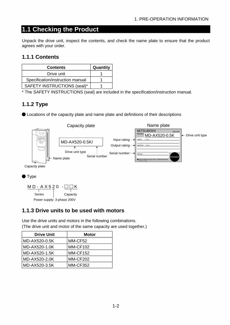
Unpack the drive unit, inspect the contents, and check the name plate to ensure that the productagrees with your order.
1.1.1 Contents
Contents Quantity
Drive unit 1
Specification/instruction manual 1
SAFETY INSTRUCTIONS (seal)* 1
* The SAFETY INSTRUCTIONS (seal) are included in the specification/instruction manual.
1.1.2 Type
Locations of the capacity plate and name plate and definitions of their descriptions
MITSUBISHIMODEL
MELIPM
MITSUBISHI ELECTRIC CORPORATIONMADE IN JAPAN
MD-AX520-0.5K INPUT :
OUTPUT :
SERIAL :
XXXXX
XXXXX
PASSED
Capacity plate
Name plate
Capacity plate
Drive unit typeSerial number
Name plate
Input ratingMD-AX520-0.5K/
Output rating
Serial number
Drive unit type
Type
A X 5 2 0M D - - K
CapacitySeries
Power supply: 3-phase 200V
1.1.3 Drive units to be used with motors
Use the drive units and motors in the following combinations.(The drive unit and motor of the same capacity are used together.)
Drive Unit Motor
MD-AX520-0.5K MM-CF52
MD-AX520-1.0K MM-CF102
MD-AX520-1.5K MM-CF152
MD-AX520-2.0K MM-CF202
MD-AX520-3.5K MM-CF352
1. PRE-OPERATION INFORMATION
1-3
1
1.2 Parts Identification
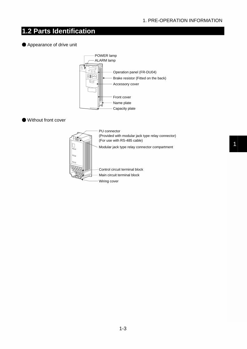
Appearance of drive unit
Capacity plate
POWER lampALARM lamp
Operation panel (FR-DU04)
Brake resistor (Fitted on the back)
Accessory cover
Front cover
Name plate
Without front cover
Wiring cover
PU connector(Provided with modular jack type relay connector)(For use with RS-485 cable)
Modular jack type relay connector compartment
Control circuit terminal block
Main circuit terminal block
1. PRE-OPERATION INFORMATION
1-4
1.3 Handling of the Cover and Operation Panel
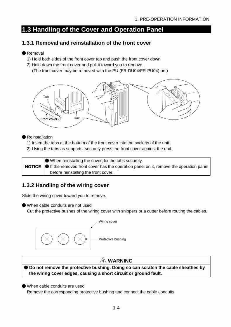
1.3.1 Removal and reinstallation of the front cover
Removal1) Hold both sides of the front cover top and push the front cover down.2) Hold down the front cover and pull it toward you to remove.
(The front cover may be removed with the PU (FR-DU04/FR-PU04) on.)
Unit
Tab
Front cover
Reinstallation1) Insert the tabs at the bottom of the front cover into the sockets of the unit.2) Using the tabs as supports, securely press the front cover against the unit.
NOTICE When reinstalling the cover, fix the tabs securely.
If the removed front cover has the operation panel on it, remove the operation panelbefore reinstalling the front cover.
1.3.2 Handling of the wiring cover
Slide the wiring cover toward you to remove.
When cable conduits are not usedCut the protective bushes of the wiring cover with snippers or a cutter before routing the cables.
Protective bushing
Wiring cover
WARNING Do not remove the protective bushing. Doing so can scratch the cable sheathes bythe wiring cover edges, causing a short circuit or ground fault.
When cable conduits are usedRemove the corresponding protective bushing and connect the cable conduits.

1. PRE-OPERATION INFORMATION
1-5
1
1.3.3 Removal and reinstallation of the operation panel
Hold down the top button of the operation panel and pull the operation panel toward you to remove.
ReinstallationRemoval
To reinstall, insert straight and mount securely.
NOTICE Do not reinstall the operation panel to the front cover which has been removed fromthe drive unit. Doing so will damage the PU connector.
Reinstallation using the connection cable1) Remove the operation panel.2) Disconnect the modular jack type relay connector. (Place the disconnected modular jack type
relay connector in the modular jack type relay connector compartment.)
Modular jack type relay connector compartment
Modular jack type relay connector
3) Securely plug one end of the connection cable into the PU connector of the drive unit and theother end into the operation panel.

1. PRE-OPERATION INFORMATION
1-6
1.4 Transportation
When carrying, always support the whole drive unit.
1.5 Storage
Store the drive unit in the following environment.
AmbienceNo corrosive gas, flammable gas, oil mist, dust and dirt.No exposure to direct sunlight. No salt.
Ambient temperature -10°C to +50°C (non-freezing)
Storage temperature -20°C to +65°C (applies to short-time transit)
Ambient humidity 90%RH or less (non-condensing)
Vibration 5.9m/s2 (conformance with JIS C 0040)
NOTICE
If the specification value of humidity is satisfied, condensation and/or freezing willoccur in places where temperatures vary greatly. Avoid storing the equipment insuch places.
Avoid placing the unit directly on the floor. Place it on a stand or shelf.

2. INSTALLATION
2-1
1
2
3
4
5
6
7
8
2. INSTALLATION
This chapter gives preparatory information on installation and wiring of the drive unit.
NOTICE
The Japanese harmonic suppression guidelines for suppression of harmonics wereestablished by the Ministry of International Trade and Industries in September,1994.To comply with the regulation levels determined by the Japan ElectricalManufacturers' Association in accordance with the "harmonic suppression guidelinefor household appliances and general-purpose products", connect the optionalpower factor improving reactor (FR-BEL or FR-BAL).
Contents of This Chapter Page
2.1 Checking the Installation Environment 2-22.1.1 Operating environment ...................................................................... 2-22.1.2 Installation in control box ................................................................... 2-3
2.2 Preparation of Peripheral Devices 2-52.2.1 Basic configuration ............................................................................ 2-52.2.2 Selection of peripheral devices .......................................................... 2-6
2.3 Installation Method 2-9

2. INSTALLATION
2-2
2.1 Checking the Installation Environment
2.1.1 Operating environment
General operating environmentInstall the unit in the following environment.
AmbienceIndoors (No corrosive gas, flammable gas, oil mist, dust and dirtNo exposure to direct sunlight. No salt.)
Ambient temperature -10°C to +50°C (non-freezing)
Ambient humidity 90%RH or less (non-condensing)
Altitude Maximum 1000m
Vibration 5.9m/s2 (conformance with JIS C 0040)
CAUTION Install the equipment on a non-flammable material. Not doing so can cause a fire. Do not place flammable materials near the equipment. Doing so can cause a fire. Install the unit in a load-bearing place. Not doing so can cause an accident.
Noise environment
Since drive is an electronic piece of equipment, the drive unit may malfunction if there are machineswhich generate large noises (e.g. welder, power equipment) in the periphery. Fit surge suppressors,noise filters and/or like to the noise sources, install the drive unit as far away as possible from noisesources, or place shielding plates and the like to fully suppress noises.
CAUTION The drive unit itself can be the source of noises. Take noise suppression measuresto prevent peripheral equipment from malfunctioning due to noises.
Refer to: Chapter 3, 3.1.2 NoisesChapter 6, 6.3 Noise Malfunctions and Measures

2. INSTALLATION
2-3
2
2.1.2 Installation in control box
When installing the drive unit in a control box, the internal temperature of the control box must notexceed the permissible value due to drive-unit generated heat and peripheral-generated heat.Placing a heat sink outside the control box can reduce the heat generated inside the control box
Refer to: Chapter 7, 7.1.3 Option list (External heat sink mounting attachment)
Measurement positions of ambient temperatures
5cm 5cm
5cmMeasurement position
Drive unitMeasurement position
Layout of drive units within control box
Ventilation fan
Drive unit
(Correct example) (Incorrect example)
Drive unit
Position of ventilation fan
Built-in cooling fans
Accommodation of two or more drive units
Drive unit Drive unitDrive unit
Drive unit
(Incorrect example)(Correct example)
NOTICE
Leave the specified clearances between the drive unit and control box walls or otherequipment. Not doing so can cause a failure. In addition, improper convection of airin the control box will reduce the heat dissipation effect. Fully consider theequipment layout in the control box and the use of a cooling fan for ventilation, forexample.
10cm or more
1cm or more
Drive unit1cm or more
These clearances are also required for replacement of the cooling fan.
Leave sufficient clearances above and under the drive unit to ensure adequate ventilation.
Cooling fan builtin the drive unit
Cooling air
10cm or more
2. INSTALLATION
2-4
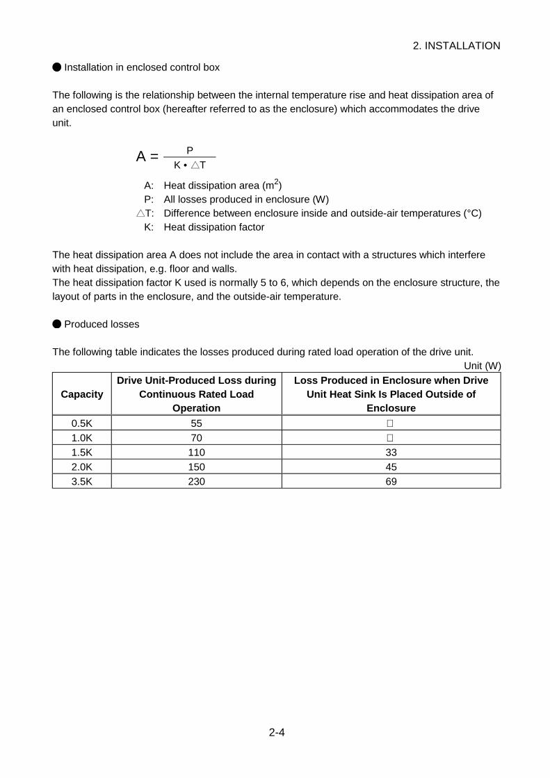
Installation in enclosed control box
The following is the relationship between the internal temperature rise and heat dissipation area ofan enclosed control box (hereafter referred to as the enclosure) which accommodates the driveunit.
PA =K • T
A: Heat dissipation area (m2)P: All losses produced in enclosure (W)T: Difference between enclosure inside and outside-air temperatures (°C)K: Heat dissipation factor
The heat dissipation area A does not include the area in contact with a structures which interferewith heat dissipation, e.g. floor and walls.The heat dissipation factor K used is normally 5 to 6, which depends on the enclosure structure, thelayout of parts in the enclosure, and the outside-air temperature.
Produced losses
The following table indicates the losses produced during rated load operation of the drive unit.Unit (W)
CapacityDrive Unit-Produced Loss during
Continuous Rated LoadOperation
Loss Produced in Enclosure when DriveUnit Heat Sink Is Placed Outside of
Enclosure
0.5K 55 1.0K 70 1.5K 110 33
2.0K 150 45
3.5K 230 69
2. INSTALLATION
2-5
2
2.2 Preparation of Peripheral Devices
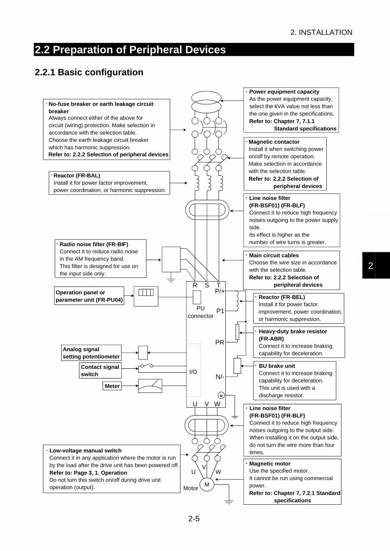
2.2.1 Basic configuration
I/O
M
U V W
R S TP/+
P1
PR
N/-
UV
W
Always connect either of the above for circuit (wiring) protection. Make selection in accordance with the selection table. Choose the earth leakage circuit breaker which has harmonic suppression.
No-fuse breaker or earth leakage circuit breaker
Refer to: 2.2.2 Selection of peripheral devices
Reactor (FR-BAL)Install it for power factor improvement, power coordination, or harmonic suppression.
Radio noise filter (FR-BIF)Connect it to reduce radio noise in the AM frequency band. This filter is designed for use on the input side only.
Operation panel or parameter unit (FR-PU04)
Analog signal setting potentiometer
Contact signal switch
Meter
Low-voltage manual switchConnect it in any application where the motor is run by the load after the drive unit has been powered off.Refer to: Page 3, 1. OperationDo not turn this switch on/off during drive unit operation (output). Motor
Power equipment capacityAs the power equipment capacity, select the kVA value not less than the one given in the specifications.Refer to: Chapter 7, 7.1.1 Standard specifications
Magnetic contactorInstall it when switching power on/off by remote operation.Make selection in accordance with the selection table.Refer to: 2.2.2 Selection of peripheral devices
Line noise filter(FR-BSF01) (FR-BLF)Connect it to reduce high frequency noises outgoing to the power supplyside.Its effect is higher as the number of wire turns is greater.
Main circuit cablesChoose the wire size in accordance with the selection table.Refer to: 2.2.2 Selection of peripheral devices
Reactor (FR-BEL)Install it for power factor improvement, power coordination, or harmonic suppression.
Heavy-duty brake resistor (FR-ABR)Connect it to increase braking capability for deceleration.
BU brake unitConnect it to increase braking capability for deceleration.This unit is used with a discharge resistor.
Line noise filter(FR-BSF01) (FR-BLF)Connect it to reduce high frequency noises outgoing to the output side. When installing it on the output side, do not turn the wire more than four times.
Magnetic motorUse the specified motor.It cannot be run using commercial power.Refer to: Chapter 7, 7.2.1 Standard specifications
PU connector
2. INSTALLATION
2-6
2.2.2 Selection of peripheral devices
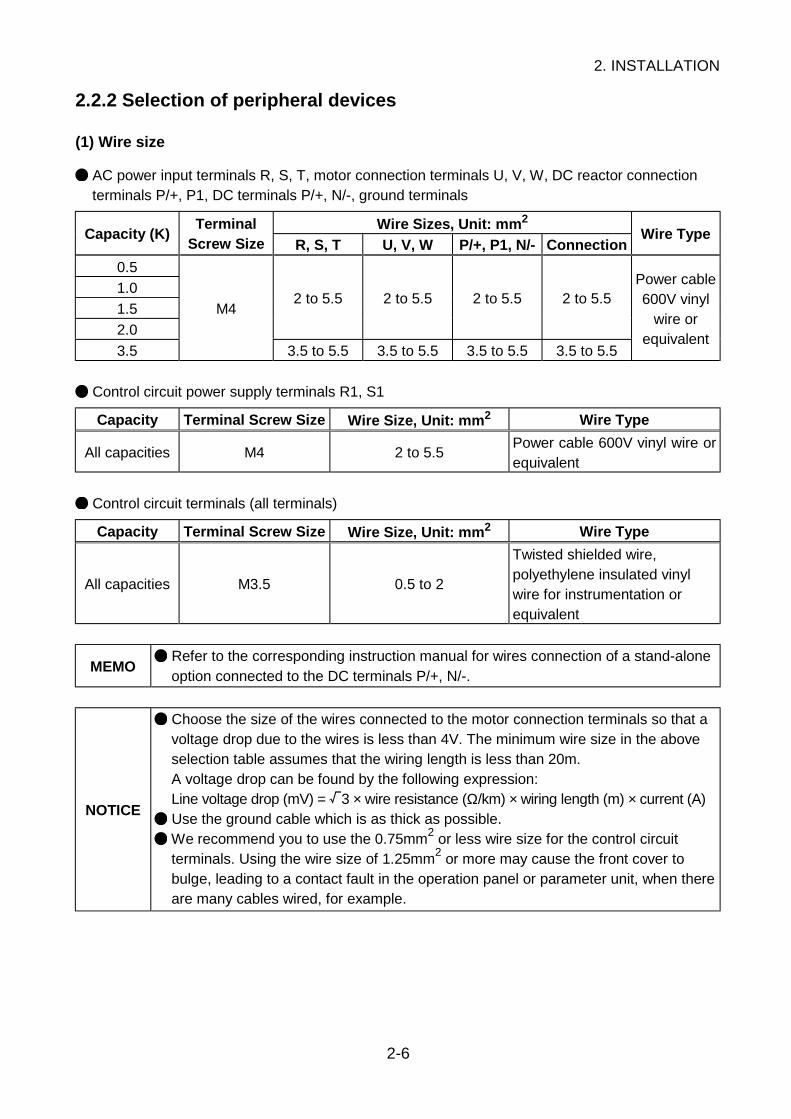
(1) Wire size
AC power input terminals R, S, T, motor connection terminals U, V, W, DC reactor connectionterminals P/+, P1, DC terminals P/+, N/-, ground terminals
Wire Sizes, Unit: mm2
Capacity (K)Terminal
Screw Size R, S, T U, V, W P/+, P1, N/- ConnectionWire Type
0.5
1.0
1.5
2.0
2 to 5.5 2 to 5.5 2 to 5.5 2 to 5.5
3.5
M4
3.5 to 5.5 3.5 to 5.5 3.5 to 5.5 3.5 to 5.5
Power cable600V vinyl
wire orequivalent
Control circuit power supply terminals R1, S1
Capacity Terminal Screw Size Wire Size, Unit: mm2 Wire Type
All capacities M4 2 to 5.5Power cable 600V vinyl wire orequivalent
Control circuit terminals (all terminals)
Capacity Terminal Screw Size Wire Size, Unit: mm2 Wire Type
All capacities M3.5 0.5 to 2
Twisted shielded wire,polyethylene insulated vinylwire for instrumentation orequivalent
MEMO Refer to the corresponding instruction manual for wires connection of a stand-aloneoption connected to the DC terminals P/+, N/-.
NOTICE
Choose the size of the wires connected to the motor connection terminals so that avoltage drop due to the wires is less than 4V. The minimum wire size in the aboveselection table assumes that the wiring length is less than 20m.A voltage drop can be found by the following expression:Line voltage drop (mV) = 3 × wire resistance (Ω/km) × wiring length (m) × current (A)
Use the ground cable which is as thick as possible.
We recommend you to use the 0.75mm2 or less wire size for the control circuitterminals. Using the wire size of 1.25mm2 or more may cause the front cover tobulge, leading to a contact fault in the operation panel or parameter unit, when thereare many cables wired, for example.

2. INSTALLATION
2-7
2
(2) Crimping terminals
Wire Size, Unit: mm2 Terminal Screw Size Crimping Terminal Size
0.5 M3.5 1.25-3.5
0.75 M3.5 1.25-3.5
1.25 M3.5 1.25-3.5
M3.5 2-3.52
M4 2-4
3.5/5.5 M4 5.5-4
(3) No-fuse breakers, magnetic contactors
No-Fuse BreakerCapacity (K) With power factor
improving reactorWithout power factor
improving reactor
Magnetic Contactor
0.5 30AF/5A
1.0 30AF/10A
1.5 30AF/15A
S-N10
2.0 30AF/15A 30AF/20A S-N11, S-N12
3.5 30AF/30A S-N20
(4) Earth leakage circuit breakers
Selection methodUse the earth leakage circuit breaker which has harmonic/surge suppression.Our product: Progressive Super Series NV-SF, NV-CF
Earth Leakage Circuit BreakerCapacity (K) With power factor
improving reactorWithout power factor
improving reactor
0.5 30AF/5A
1.0 30AF/10A
1.5 30AF/15A
2.0 30AF/15A 30AF/20A
3.5 30AF/30A
MEMO
Leakage currents from the wiring and motor include frequency components of ahigher degrees than those from the commercial power supply. Therefore, the earthleakage circuit breaker which is not a harmonic/surge suppression product cancause unnecessary operations.<Measures against unnecessary operations>• Minimize the wiring distance of I/O cables.• Run I/O cables away (more than 30cm) from the earth.• Reduce the Pr. 72 "motor tone selection" setting.

2. INSTALLATION
2-8
Setting of rated current sensitivityRated current sensitivity ≥ 10 lg1 + lgn + K (lg2 + lgm)
K: Constant in consideration of harmonics
Earth Leakage Circuit Breaker
Type Our productK
Harmonic/surgesuppression product
NV-SFNV-CF
1
NV
Ig1 Ign Ig2 Igm
MDrive unit
Noisefilter
General productNV-CANV-CSNV-SS
3
lg1: Leakage current in cable path between earth leakage circuit breaker and drive unit (see Fig. 2-2)lg2: Leakage current in cable path between drive unit and motor (see Fig. 2-2)
0
20
40
60
80
100
120
2 3.55.5
8 14223038
6080100
150
(200V 60Hz)
Fig. 2-2 Example of Leakage Current per 1km of Cable Path When CV Cable Is Routed in Metal Conduit
Wire size (mm )
Lea
kage
cur
rent
(m
A)
2
lgn: Leakage current of filter connected on input sideRefer to Chapter 7, 7.1.3 Option list for our dedicated filters.
lgm: Leakage current of motor
Capacity (K) Leakage Current (mA)
0.5, 1.0 0.1
1.5, 2.0 0.2
3.5 0.3
NOTICE
Install the leakage current circuit breaker on the input side (power supply side) ofthe drive unit.Installation on the output side will cause the earth leakage circuit breaker tooverheat or malfunction.
MEMO A leakage current may flow into the other lines through the ground cables, etc.
2. INSTALLATION
2-9
2
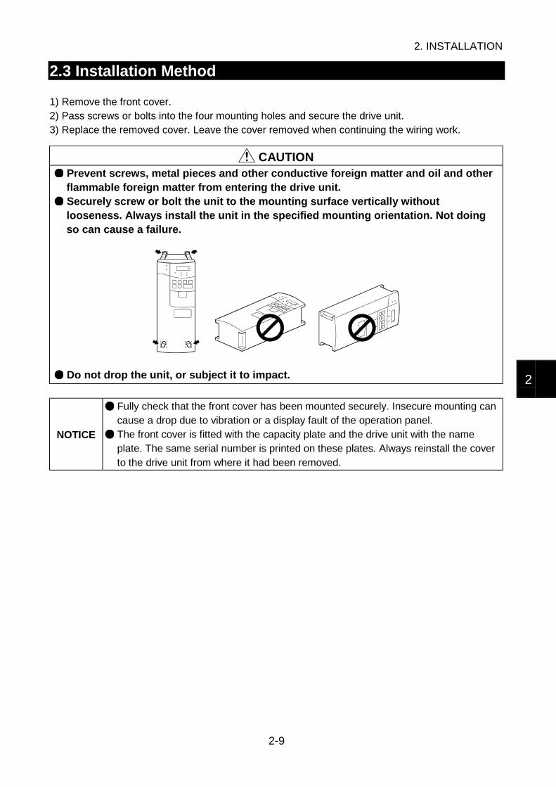
2.3 Installation Method
1) Remove the front cover.2) Pass screws or bolts into the four mounting holes and secure the drive unit.3) Replace the removed cover. Leave the cover removed when continuing the wiring work.
CAUTION Prevent screws, metal pieces and other conductive foreign matter and oil and otherflammable foreign matter from entering the drive unit. Securely screw or bolt the unit to the mounting surface vertically withoutlooseness. Always install the unit in the specified mounting orientation. Not doingso can cause a failure.
Do not drop the unit, or subject it to impact.
NOTICE
Fully check that the front cover has been mounted securely. Insecure mounting cancause a drop due to vibration or a display fault of the operation panel.
The front cover is fitted with the capacity plate and the drive unit with the nameplate. The same serial number is printed on these plates. Always reinstall the coverto the drive unit from where it had been removed.

3. WIRING
3-1
1
2
3
4
5
6
7
8
3. WIRING
This chapter describes the wiring of the drive unit.
WARNING Any person who is involved in the wiring of this equipment should be fullycompetent to do the work. Otherwise, an electric shock or fire can occur. Always install the unit before wiring. Otherwise, an electric shock or fire can occur. Before restarting wiring after switching power "ON", make sure that the motor is ata stop, wait for more than 10 minutes after switching power "OFF", and confirm thatthe DC voltage across the DC terminals P/+ and N/- is low enough to do wiring.Immediately after power "OFF", the DC terminals P/+, N/- are charged with morethan 200V (residual voltage of the internal capacitor). Therefore, an electric shockmay occur. Even after power-off, the motor connection terminals U, V, W have high voltageswhile the motor is running. Always start wiring after confirming that the motor hasstopped. Not doing so can cause an electric shock.
CAUTION Take measures to prevent peripheral sensors and equipment from malfunctioningdue to electromagnetic noises. Not doing so can cause accidents. Take measures to prevent peripheral power capacitors and generators fromoverheating or being damaged due to power harmonics. Not doing so can cause afire. Do not leave wire offcuts in the drive unit. Doing so can cause a fault, failure ormalfunction. If the machine must not be restarted when power is restored after a power failure,provide a magnetic contactor on the power supply side and also make up asequence which will not turn "ON" the start signal automatically when power isrestored. Tighten the terminal screws to the specified torque. Undertightening can cause aninter-terminal short circuit or malfunction. Overtightening can cause the screws andunit to be damaged, resulting in a short circuit, malfunction or the like. When using the unit having a built-in brake resistor or using the brake resistor(option), switch power off with the alarm signal of the unit. If you do not so, a braketransistor failure or like may overheat the brake resistor abnormally, causing a fire.
Contents of This Chapter Page
3.1 Pre-Wiring Instructions 3-33.1.1 Terminal connection diagram............................................................. 3-33.1.2 Noises ............................................................................................... 3-4
3. WIRING
3-2
3.2 Wiring of the Main Circuit Terminals 3-53.2.1 Terminals........................................................................................... 3-53.2.2 Terminal layout and connection specifications ................................... 3-53.2.3 Wiring of the AC power input terminals R, S, T .................................. 3-63.2.4 Wiring of the control circuit power supply terminals R1, S1................ 3-63.2.5 Wiring of the motor connection terminals U, V, W.............................. 3-73.2.6 Wiring of the ground terminals ...................................................... 3-73.2.7 Wiring of the DC reactor connection terminals P/+, P1 ...................... 3-83.2.8 Wiring of the brake resistor connection terminals P/+, PR ................. 3-83.2.9 Wiring of the DC terminals P/+, N/- .................................................... 3-9
3.3 Wiring of the Control Circuit Terminals 3-113.3.1 Terminals......................................................................................... 3-113.3.2 Terminal layout and connection specifications ................................. 3-143.3.3 Switching between sink logic and source logic................................. 3-153.3.4 Wiring of the contact input terminals ................................................ 3-163.3.5 Wiring of the speed command input terminals ................................. 3-173.3.6 Wiring of the transistor output terminals........................................... 3-183.3.7 Wiring of the contact output terminals .............................................. 3-193.3.8 Wiring of the instrument connection terminals.................................. 3-19
3.4 Wiring of the PU Connector 3-203.4.1 Pin layout......................................................................................... 3-203.4.2 Using the cable to connect the operation panel ............................... 3-203.4.3 System configuration examples for communication operations........ 3-203.4.4 Wiring methods for communication operation .................................. 3-22
3. WIRING
3-3
3
3.1 Pre-Wiring Instructions
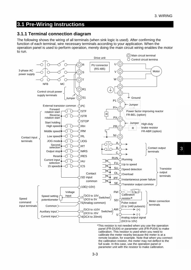
3.1.1 Terminal connection diagramThe following shows the wiring of all terminals (when sink logic is used). After confirming thefunction of each terminal, wire necessary terminals according to your application. When theoperation panel is used to perform operation, merely doing the main circuit wiring enables the motorto run.
NFB
R
R
S
T
U
V
W
R1
S1
PC
STF
STR
STOP
RH
RM
RL
JOG
RT
MRS
RES
AU
CS
SD
2
P1
P/+
PXR
PR
A
B
C
RUN
FU
SU
OL
IPF
SE
FM
SD
AM
5
MC
3-phase AC power supply
Control circuit power supply terminals
Jumper
External transistor common
Contact input terminals
rotation start
rotation start
Start holding
Low speed
High speed
Middle speed
JOG mode
selection
Output stop
Reset
selection15 speeds
Speedcommandinput terminals
Speed settingpotentiometer
Voltageinput
Common
Auxiliary input
Current input
Drive unit
PU connector(RS-485)
Contact input common
10E(+10V)
5(Analog common)
Switched1DC0 to 10VDC0 to 5V+
+
DC0 to 10VDC0 to 5V
Switched
4(DC4 to 20mA)
N/
Control circuit termina
Main circuit terminal
Power factor improving reactorFR-BEL (option)
Motor
Ground
Jumper
Overload
Jumper High-duty brake resistorFR-ABR (option)
Contact output terminals
Running
Up to speed
Speed detection Transistoroutputterminals
Instantaneous power failure
Transistor output common
+
Calibration resistor
(+)
(+)Analog output signal(DC0 to 10V)
Pulse output(0 to 1440 pulses/s)
Meter connection terminals
Forward
Reverse
Current input
Second
*This resistor is not needed when you use the operationpanel (FR-DU04) or parameter unit (FR-PU04) to makecalibration. This resistor is used when you need tocalibrate the meter nearby because the meter is at aremote location, for example. Note that when you connectthe calibration resistor, the meter may not deflect to thefull scale. In this case, use the operation panel orparameter unit with the resistor to make calibration.

3. WIRING
3-4
3.1.2 Noises
Take the following measures if you want to further suppress noises which affect the drive unit orwhen there are devices nearby which are susceptible to noises (e.g. measuring instruments,telephone lines, various sensors).
(1) When noises are expected from the drive unit signal cables Fit data line filters to the signal cables.
(2) When there are devices nearby which are connected to the power supply whose lineis different from that of the drive unit
Run the signal cables of the device as far away as possible from the drive unit and its powercable.
Avoid the parallel wiring and bundling of the device's signal cables and the drive unit's powercable.
Connect a line noise filter to the input or output side of the drive unit's power cable.
Connect a radio noise filter to the input side of the drive unit's power cable.
Use shielded cables as the signal and power cables.
Run the signal and power cables in separate metal conduits.
(3) When there are devices which are connected to the power supply whose line is thesame as that of the drive unit
Connect a line noise filter to the input or output side of the drive unit's power cable.
Connect a radio noise filter to the input side of the drive unit's power cable.
NOTICE
The effects of the above noise suppression techniques depend on the propagationpaths of noises and the noise immunities of the devices.
Refer to: Chapter 6, 6.3 Noise Malfunctions and Measures

3. WIRING
3-5
3
3.2 Wiring of the Main Circuit Terminals
3.2.1 Terminals
Symbols Name Description
R, S, TAC power inputterminals
Connect to the commercial power supply.
U, V, WMotor connectionterminals
Connect to a dedicated variable-speed synchronous motor.
R1, S1Control circuit powersupply terminals
Connected to the AC power input terminals R, S. To retainthe alarm display and alarm output, remove the jumpers fromthe terminal block (across R-R1 and S-S1) and input externalpower to these terminals.
P/+, PRBrake resistorconnection terminals
Disconnect the jumper from terminals PR-PX and connect theFR-ABR brake resistor (option).
P/+, P1DC reactorconnection terminals
Disconnect the jumper from terminals P/+-P1 and connect theFR-BEL power factor improving DC reactor (option).
P/+, N/- DC terminalsConnect to the BU brake unit (option) or FR-HC high powerfactor converter (option).
PR, PXBuilt-in brake circuitconnection terminals
When the jumper is connected across terminals PX-PR(factory setting), the built-in brake circuit is enabled.
Ground terminalsTerminals for connection of the ground cables. (There are twoterminals.)
3.2.2 Terminal layout and connection specifications
AX520-0.5, 1.0K AX520-1.5K to 3.5K
LayoutR
R1
S T U V W PR
S1 P1 PXP/+N/ -
Charge lampJumper
LayoutR
R1
S T U V W PR
S1
P1
PX
N/ - P/+
Charge lamp
Jumper
Screw sizeM4
Tightening torque1.5N•m
Screw sizeM4
Tightening torque1.5N•m
CAUTION Tighten the terminal screws to the specified torque. Undertightening can cause aninter-terminal short circuit or malfunction. Overtightening can cause the screws andunit to be damaged, resulting in a short circuit malfunction or the like.

3. WIRING
3-6
3.2.3 Wiring of the AC power input terminals R, S, T
Connect these terminals to the AC power supply. You need not match the phase sequence.
R S T
R S T
Power supply
No-fuse breaker
CAUTION Always apply power to only the AC power input terminals R, S, T and control circuitpower supply terminals R1, S1. Applying power to the other terminals will damagethe unit.
3.2.4 Wiring of the control circuit power supply terminals R1, S1
Wire these terminals when you want to supply the control circuit power of the drive unit to retain thealarm signal if the magnetic contactor (MC) on the power supply side is opened to switch off maincircuit power when the protective circuit is activated.
1) Remove the jumpers across the terminals R-R1, S-S1.2) Wire the terminals R1, S1 from the primary side of the magnetic contactor.
RS T
R1 S1
1) Loosen the upper screws.2) Remove the lower screws.3) Remove the jumpers.
Main circuit terminal block
MEMO An error display (E.OC1) will be provided if you turn on the start signal with powersupplied to only the R1 and S1 terminals.
CAUTION When you have energized the AC power input terminals R, S, T, always energize thecontrol circuit power supply terminals R1, S1, too. The drive unit may be damaged ifyou energize the AC power input terminals without the control circuit power supplyterminals being energized. Before wiring the control circuit power supply terminals, always remove thejumpers across the terminals R-R1 and across the terminals S-S1. Not doing so cancause a power supply short circuit.

3. WIRING
3-7
3
3.2.5 Wiring of the motor connection terminals U, V, W
Connect these terminals to the motor. Match the phase sequence of the motor connection terminalsU, V, W with that of the motor cables. Incorrect phase sequence will run the motor in reverse.
U V W
U V W
Motor
CAUTION The wiring length between the drive unit and motor should be 100m maximum. Longwiring may cause torque to be insufficient or the overcurrent protection function tobe activated. Between the drive unit and motor, do not fit a power capacitor, surge suppressor orFR-BIF radio noise filter (option).
3.2.6 Wiring of the ground terminals
There are two ground terminals. Connect one ground terminal to the motor's ground terminal andperform shared grounding on the drive unit.
MotorDrive unit
NOTICE
Avoid shared grounding with the other equipment susceptible to noise, and performexclusive or single-point grounding.
Drive unit Drive unit Drive unitOther
equipmentOther
equipmentOther
equipment
Shared grounding Not allowed Exclusive grounding Allowed 1-point grounding Allowed
WARNING Ground the drive unit and motor securely to prevent an electric shock due toleakage currents. (Class D grounding, grounding resistance 100ΩΩΩΩ max.) For grounding, connect the cable to the exclusive ground terminal. (Do not use thescrew of the casing, chassis or the like.)

3. WIRING
3-8
3.2.7 Wiring of the DC reactor connection terminals P/+, P1
These terminals are designed for connection of the power factor improving reactor (FR-BEL).Remove the jumper across the terminals P/+-P1 and connect the DC reactor.
P1FR-BEL
P/ +
Remove jumper.
NOTICE The wiring distance (overall length) should be within 5m.
MEMO Without removal of the jumper, the reactor will not be active.
3.2.8 Wiring of the brake resistor connection terminals P/+, PR
These terminals are designed for connection of the heavy-duty brake resistor.1) Remove the screws in the terminals PR and PX and disconnect the jumper.
Terminal PX
Terminal PR
Jumper
2) Connect the brake resistor to the terminals P/+, PR.
FR-AX520-0.5K, 1.0K FR-AX520-1.5K to 3.5K
Terminal P/+
Terminal PR Terminal PRTerminal P/+
3) Change the Pr. 30 and Pr. 70 settings.
NOTICE Always remove the jumper across the terminals PR-PX. Connect only the specified brake resistor.

3. WIRING
3-9
3
3.2.9 Wiring of the DC terminals P/+, N/-
These terminals are designed for connection of the BU brake unit or high power factor converter.
For connection of BU brake unit1) Remove the jumper across the terminals PR-PX.2) Connect the BU brake unit. For full information, read the BU brake unit instruction manual.3) Change the Pr. 30 setting.
R
S
T
U
VW
M
NFB
PR
PX
P N
P/ + N/ -
BU brake unit
Motor
Remove jumper.
CAUTION Do not connect the brake resistor or the like to the DC terminals P/+, N/- directly.Doing so can cause a fire. Incorrect (opposite) connection to the DC terminals P/+, N/- will damage the driveunit.
For connection of high power factor converter (FR-HC)1) Connect the control circuit power supply terminals R1, S1 to the power supply.
Refer to: 3.2.4 Wiring of the control circuit power supplyterminals R1, S1
Do not connect the AC power input terminals R, S, T of the drive unit.2) Select sink logic (factory setting) as the control logic of the control circuit contact input
terminals.The converter cannot use source logic.
Refer to: 3.3.3 Switching between sink logic and source logic3) Assign the X10 signal to the control circuit contact input terminal of the drive unit.
Refer to: Chapter 8, 8.4 Selection of the Control Circuit ContactInput Terminal Functions
4) Connect the high power factor converter. For details, refer to the high power factor converterinstruction manual.
5) Change the Pr. 30 setting.

3. WIRING
3-10
X10 (MRS)
R1S1
RESSD
TSR
MRDYNP
RSOSE
VU
W
P/+N/ -
Motor
Power supply
High power factor converter(FR-HC) Drive unit
CAUTION Do not connect a power supply to the AC power input terminals R, S, T of the driveunit. Doing so will damage the drive unit. Opposite polarity (reverse connection) of the DC terminals P/+, N/- will damage thedrive unit.

3. WIRING
3-11
3
3.3 Wiring of the Control Circuit Terminals
CAUTION Use shielded or twisted cables for wiring the control circuit input terminals. Alsorun them away from the main circuit wiring and other power cables. Not doing socan cause a malfunction due to noise.
3.3.1 Terminals
After confirming the function of each terminal, use necessary terminals according to your application.
(1) Contact input terminals Turning the signal across any terminal and common terminal "ON" (closing thoseterminals)/"OFF" (opening those terminals) provides the corresponding function as describedbelow.
The shaded terminal symbols indicate that their functions can be changed.Refer to: Chapter 8, 8.4 Selection of the Control Circuit Contact
Input Terminal Functions
Symbol Name Description
STFForward rotationstart
Turn on this signal to start forward rotation orturn it off to stop.
STRReverse rotationstart
Turn on this signal to start reverse rotation orturn it off to stop.
Simultaneouslyturning on thesesignals gives a stopcommand.
STOP Start holding Used to self-hold the start signal.
RES ResetTurn on this signal (for more than 0.1s) to reset the protective circuitactivated. Turn it off after the protective circuit is reset.
MRS Output stopTurn on this signal (for more than 0.1s) to stop the output andseparate the motor electrically, causing it to coast. Turing it off withthe start signal input will restart the motor at the starting speed.
RH High speedRM Middle speedRL Low speedCS 15 speeds
Combine on/off of these signals as appropriate to select multiplespeeds.
Refer to: Chapter 8, 8.3.2 Variable-speedoperation using contact input signals
JOG JOG mode Turn on this signal to start jog operation.
RT Second selectionTurn on this signal to select the second acceleration/decelerationtime.
AUCurrent inputselection
Turn on this signal to choose the speed command of the terminal 4(current input), enabling operation using the 4 to 20mA currentsignal.
SDContact inputcommon
Common to the contact input terminals. (When sink logic is used)
Common terminal used when the contact input terminal is connectedto the transistor output (open collector output) of the externalcontroller. This terminal can prevent a malfunction caused by asneak current.
PCExternaltransistorcommon
This terminal acts as a common terminal when the contact inputterminal uses source logic.
3. WIRING
3-12
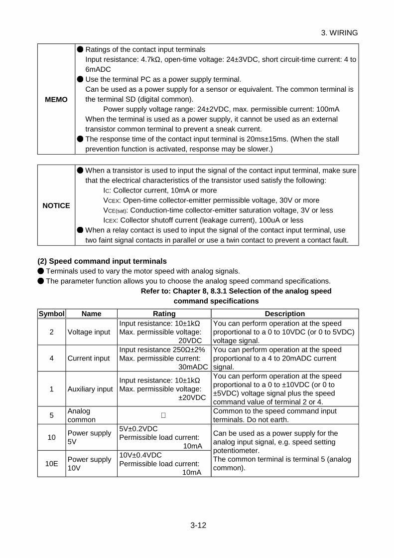
MEMO
Ratings of the contact input terminalsInput resistance: 4.7kΩ, open-time voltage: 24±3VDC, short circuit-time current: 4 to6mADC Use the terminal PC as a power supply terminal.Can be used as a power supply for a sensor or equivalent. The common terminal isthe terminal SD (digital common).
Power supply voltage range: 24±2VDC, max. permissible current: 100mAWhen the terminal is used as a power supply, it cannot be used as an externaltransistor common terminal to prevent a sneak current. The response time of the contact input terminal is 20ms±15ms. (When the stallprevention function is activated, response may be slower.)
NOTICE
When a transistor is used to input the signal of the contact input terminal, make surethat the electrical characteristics of the transistor used satisfy the following:
IC: Collector current, 10mA or moreVCEX: Open-time collector-emitter permissible voltage, 30V or moreVCE(sat): Conduction-time collector-emitter saturation voltage, 3V or lessICEX: Collector shutoff current (leakage current), 100uA or less
When a relay contact is used to input the signal of the contact input terminal, usetwo faint signal contacts in parallel or use a twin contact to prevent a contact fault.
(2) Speed command input terminals Terminals used to vary the motor speed with analog signals. The parameter function allows you to choose the analog speed command specifications.
Refer to: Chapter 8, 8.3.1 Selection of the analog speedcommand specifications
Symbol Name Rating Description
2 Voltage inputInput resistance: 10±1kΩMax. permissible voltage:
20VDC
You can perform operation at the speedproportional to a 0 to 10VDC (or 0 to 5VDC)voltage signal.
4 Current inputInput resistance 250Ω±2%Max. permissible current:
30mADC
You can perform operation at the speedproportional to a 4 to 20mADC currentsignal.
1 Auxiliary inputInput resistance: 10±1kΩMax. permissible voltage:
±20VDC
You can perform operation at the speedproportional to a 0 to ±10VDC (or 0 to±5VDC) voltage signal plus the speedcommand value of terminal 2 or 4.
5Analogcommon
Common to the speed command inputterminals. Do not earth.
10Power supply5V
5V±0.2VDCPermissible load current:
10mA
10EPower supply10V
10V±0.4VDCPermissible load current:
10mA
Can be used as a power supply for theanalog input signal, e.g. speed settingpotentiometer.The common terminal is terminal 5 (analogcommon).

3. WIRING
3-13
3
(3) Transistor output terminals When the function of any terminal is activated, the internal transistor (open collector output)connected across that terminal and common terminal turns ON (conducts). You can set the parameter function to change the function of each terminal.
Refer to: Chapter 8, 8.7.2 Selection of the control circuit outputterminal functionsChapter 8, 8.7.3 Detection of running speed
Symbol Name Description
RUN RunningON (conducts) while the drive unit is outputting a speed command to themotor. OFF (does not conduct) during voltage braking operation, stop, orcoasting.
FUSpeeddetection
Turns ON (conducts) when the speed output by the drive unit reaches orexceeds the preset value. OFF (does not conduct) when the speed isless than that.
SU Up to speedTurns ON (conducts) when the speed output by the drive unit reaches thepreset value. OFF (does not conduct) when the speed is less than thepreset value.
OLOverloadalarm
Turns ON (conducts) when stall prevention is activated. OFF (does notconduct) when stall prevention is deactivated. (Minimum width of ON-timeoutput signal: 100ms)
Refer to : Pr. 22 [Section 8.5.6]
IPFInstantaneouspower failure
Turns ON (conducts) when instantaneous power failure or undervoltageprotection is activated.
SETransistoroutputcommon
Common to the transistor output terminals. Isolated from the terminalsSD, 5.
MEMO Ratings of transistor output terminals
Max. permissible voltage: 27VDC, max. permissible current: 0.1ADC
NOTICE When driving a coil load, connect a diode.
Refer to: 3.3.6 Wiring of the transistor output terminals
(4) Contact output terminals When the protective function is activated, the relay contact connected to the terminalopens/closes
Refer to: Chapter 6, 6.1.1 Protective function activated You can set the parameter function to change the function of each terminal.
Refer to: Chapter 8, 8.7.2 Selection of the control circuit outputterminal functions
Symbol Contact Capacity Description
A, B, C200VAC 0.3A or30VDC 0.3A
Normal : Terminals B-C closed (Terminals A-Copen)
Protective function activated: Terminals B-C open (Terminals A-C closed)
MEMO
The response time of the contact output terminals is less than 100ms. (After driveunit output shutoff) When the drive unit is powered off, the contact output is placed in a normal status.Therefore, the contact output signal is not held when power is switched off after theprotective function has been activated. When the signal must be held, provide anexternal holding circuit or use the control circuit power supply terminals R1, S1.

3. WIRING
3-14
(5) Instrument connection terminals Used to display the motor speed externally. You can use the parameter function to choose the item other than the motor speed
Refer to: Chapter 8, 8.7.5 Selection of the instrumentconnection terminal functions
Symbol Name Description
FMMeterconnection
The output voltage has an 8VDC pulse waveform.The output varies in proportion to the motor speed and the averagevoltage is preset to approx. 4.7V at the rated speed and 1440 pulses/s.As a meter, use a 1mA moving-coil type DC ammeter or digital counter.As the common terminal, use terminal SD (digital common).
AMAnalog signaloutput
The output varies in proportion to the motor speed and is preset to10VDC at the rated speed.The common terminal is terminal 5 (analog common).
MEMO The output signals from the terminals FM and AM are updated at intervals of several10 ms.
3.3.2 Terminal layout and connection specifications
Layout
A
RL
SE RUN SU IPF OL FU SD STF STR JOG CS
RM RH RT AU STOP MRS RES SD FM
B C PC AM 10E 10 2 5 4 1
Screw sizeM3.5
Tightening torque1.2N•m

3. WIRING
3-15
3
3.3.3 Switching between sink logic and source logic
Description
Sink Logic Source Logic
In this logic, a signal turns ON when a currentflows out of the input terminal.
In this logic, a signal turns ON when a currentflows into the input terminal.
To use the contact input terminals as source logic, the connector on the back of the control circuitterminal block must be moved to the other position. The control logic is factory-set to sink logic.
MEMO You need not change the connector position when using only the transistor outputterminals as source logic.
To use the terminals as source logic, change the setting in the following procedure.
1) Loosen the two mounting screws on both ends of the control circuit terminal block. (Thescrews cannot be removed.)
2) With both hands, pull down the terminal block from the back of the control circuit terminals.
Loosen. Loosen.
3) Change the connector position on the back of the terminal block from "SINK" to "SOURCE".
CON1
SIN
KC
ON
3
CO
N2
SO
UR
CE
SIN
KC
ON
3
CO
N2
SO
UR
CE
4) Reinstall the control circuit terminal block in the original position and fix it with the screws.
NOTICE
While power is on, never disconnect the control circuit terminal block. Check the control circuit connector CON1 to ensure that the pins are fitted properlywithout bending. Make sure that the logic changing connector is inserted correctly. The logic changing connector is a small component. Handle it with care whenchanging the logic. The logic changing connector must be fitted in only one of the above positions.Fitting it in both positions at the same time can cause a failure.

3. WIRING
3-16
3.3.4 Wiring of the contact input terminals
Use shielded or twisted shielded cables for wiring. Connect one shield sheath to the commonterminal of the corresponding logic connection. Leave the other shield sheath open.
When using contact signalsThe following shows the wiring of the terminals STF, STR. The same wiring also applies to theother terminals.
Sink Logic Source Logic
The terminal SD is a common terminal.
R
R
STF
STR
SD
DC24V
Drive unit
The terminal PC is a common terminal.
PC
STF
STRR
R
DC24V
Drive unit
When using non-contact switchesWhen using transistor outputs having an external power supply, such as a PLC, to input signals,perform the following wiring to prevent a malfunction caused by a sneak current from the externalpower supply.The following shows the wiring of the terminals STF, STR. The same wiring also applies to theother terminals.
Sink Logic Source Logic
The terminal PC is a common terminal.
1
2
9
10
SD
PC
STR
STF
External power supply
PLC Drive unit
DC24V
The terminal SD is a common terminal.
9
1
2
10
PC
STF
STR
SD
DC24V
Drive unitPLC
External power supply
3. WIRING
3-17
3
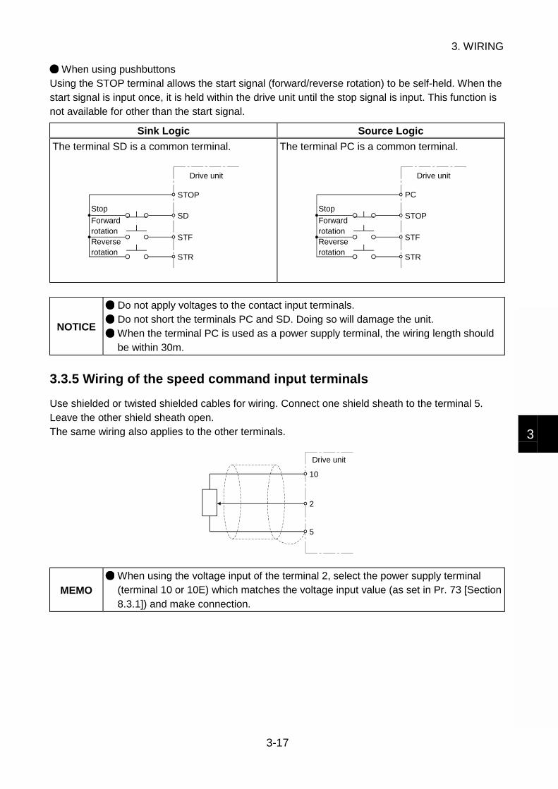
When using pushbuttonsUsing the STOP terminal allows the start signal (forward/reverse rotation) to be self-held. When thestart signal is input once, it is held within the drive unit until the stop signal is input. This function isnot available for other than the start signal.
Sink Logic Source Logic
The terminal SD is a common terminal.
STOP
SD
STF
STR
Drive unit
Reverse rotation
Stop
Forward rotation
The terminal PC is a common terminal.
STF
STR
Drive unit
Reverse rotation
Stop
Forward rotation
PC
STOP
NOTICE
Do not apply voltages to the contact input terminals. Do not short the terminals PC and SD. Doing so will damage the unit. When the terminal PC is used as a power supply terminal, the wiring length shouldbe within 30m.
3.3.5 Wiring of the speed command input terminals
Use shielded or twisted shielded cables for wiring. Connect one shield sheath to the terminal 5.Leave the other shield sheath open.The same wiring also applies to the other terminals.
10
2
5
Drive unit
MEMO
When using the voltage input of the terminal 2, select the power supply terminal(terminal 10 or 10E) which matches the voltage input value (as set in Pr. 73 [Section8.3.1]) and make connection.
3. WIRING
3-18
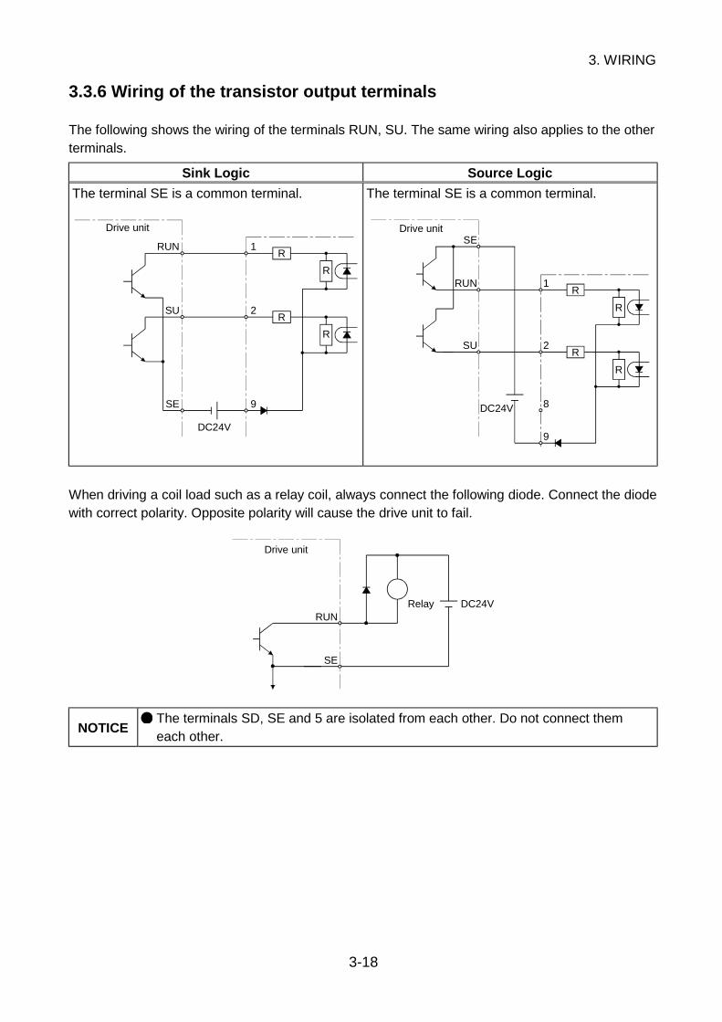
3.3.6 Wiring of the transistor output terminals
The following shows the wiring of the terminals RUN, SU. The same wiring also applies to the otherterminals.
Sink Logic Source Logic
The terminal SE is a common terminal.
RUN
SU
SE
1
2
9
R
R
R
R
DC24V
Drive unit
The terminal SE is a common terminal.
DC24V
RUN
SU
SE
1
2
9
R
R
R
R
8
Drive unit
When driving a coil load such as a relay coil, always connect the following diode. Connect the diodewith correct polarity. Opposite polarity will cause the drive unit to fail.
DC24VRUN
SE
Relay
Drive unit
NOTICE The terminals SD, SE and 5 are isolated from each other. Do not connect themeach other.
3. WIRING
3-19
3
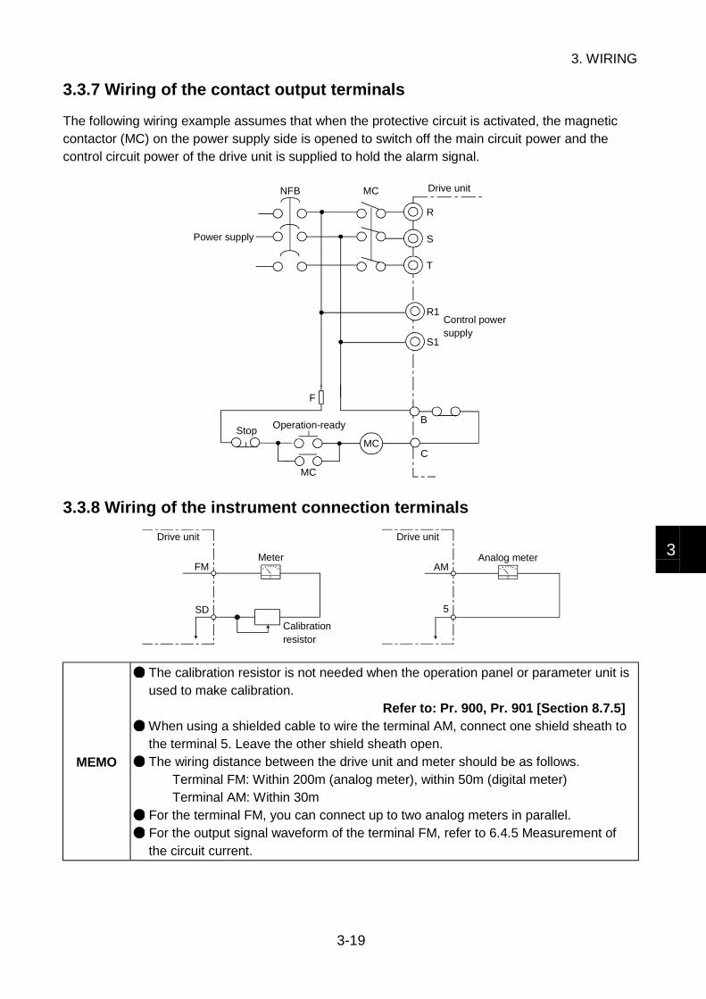
3.3.7 Wiring of the contact output terminals
The following wiring example assumes that when the protective circuit is activated, the magneticcontactor (MC) on the power supply side is opened to switch off the main circuit power and thecontrol circuit power of the drive unit is supplied to hold the alarm signal.
R
S
T
R1
S1
B
CMC
F
MC
NFB MC
Operation-ready
Power supply
Drive unit
Control power supply
Stop
3.3.8 Wiring of the instrument connection terminals
FM
SD
AM
5
Drive unit
Meter
Calibration resistor
Analog meter
Drive unit
MEMO
The calibration resistor is not needed when the operation panel or parameter unit isused to make calibration.
Refer to: Pr. 900, Pr. 901 [Section 8.7.5] When using a shielded cable to wire the terminal AM, connect one shield sheath tothe terminal 5. Leave the other shield sheath open. The wiring distance between the drive unit and meter should be as follows.
Terminal FM: Within 200m (analog meter), within 50m (digital meter)Terminal AM: Within 30m
For the terminal FM, you can connect up to two analog meters in parallel. For the output signal waveform of the terminal FM, refer to 6.4.5 Measurement ofthe circuit current.

3. WIRING
3-20
3.4 Wiring of the PU Connector
3.4.1 Pin layout
As seen from the drive unit (receptacle side) front
1) SG2) P5S3) RDA4) SDB
5) SDA6) RDB7) SG8) P5S
8)to1)
NOTICE Pins No. 2 and 8 (P5S) provide power to the operation panel. Do not use themwhen making RS-485 communication.
3.4.2 Using the cable to connect the operation panel
Use the optional "FR-CB2 parameter unit connection cable" or commercially available connectorand cable for wiring.
ConnectorRJ45 connectorExample: 5-554720-3, Tyco Electronics Corporation
CableCable conforming to EIA568 (such as 10BASE-T cable)Example: SGLPEV 0.5mm × 4P (Twiced pair cable, 4 pairs), Mitsubishi Cable
Industries, Ltd.
NOTICE The maximum wiring length is 20m.
3.4.3 System configuration examples for communication operations
1) For RS-485 communication operation
Computer
RS-485 interface/terminal
10BASE-T cable
Station No. 1 Station No. 2 Station No. n
Drive unit
PU connector
SplitterTerminating resistor
Drive unit
PU connector
Drive unit
PU connector

3. WIRING
3-21
3
Parts used (Use commercially available parts for wiring)
ConnectorRJ45 connectorExample: 5-554720-3, Tyco Electronics Corporation
CableCable conforming to EIA568 (such as 10BASE-T cable)Example: SGLPEV 0.5mm × 4P (Twisted pair cable, 4 pairs), Mitsubishi Cable
Industries, Ltd.
2) For RS-232C communication operation
Computer
10BASE-T cable
Station No. 1 Station No. 2 Station No. n
Drive unit
PU connector
SplitterTerminating resistor
Drive unit
PU connector
Drive unit
PU connector
RS-485 terminal
Converter
connector
cable
Max. 15mRS-232C
RS-232C
Parts used (Use commercially available parts for wiring)
ConnectorRJ45 connectorExample: 5-554720-3, Tyco Electronics Corporation
CableCable conforming to EIA568 (such as 10BASE-T cable)Example: SGLPEV 0.5mm × 4P (Twisted pair cable, 4 pairs), Mitsubishi Cable
Industries, Ltd.
Commerciallyavailableconverter
Examples Model: FA-T-RS40 converterNagoya Sales Office Mitsubishi Electric Engineering Co., Ltd.
NOTICE
Do not connect the PU connector to the computer's LAN board, FAX modem socketor telephone modular connector. Doing so may damage the drive unit due toelectrical incompatibilities.
3. WIRING
3-22
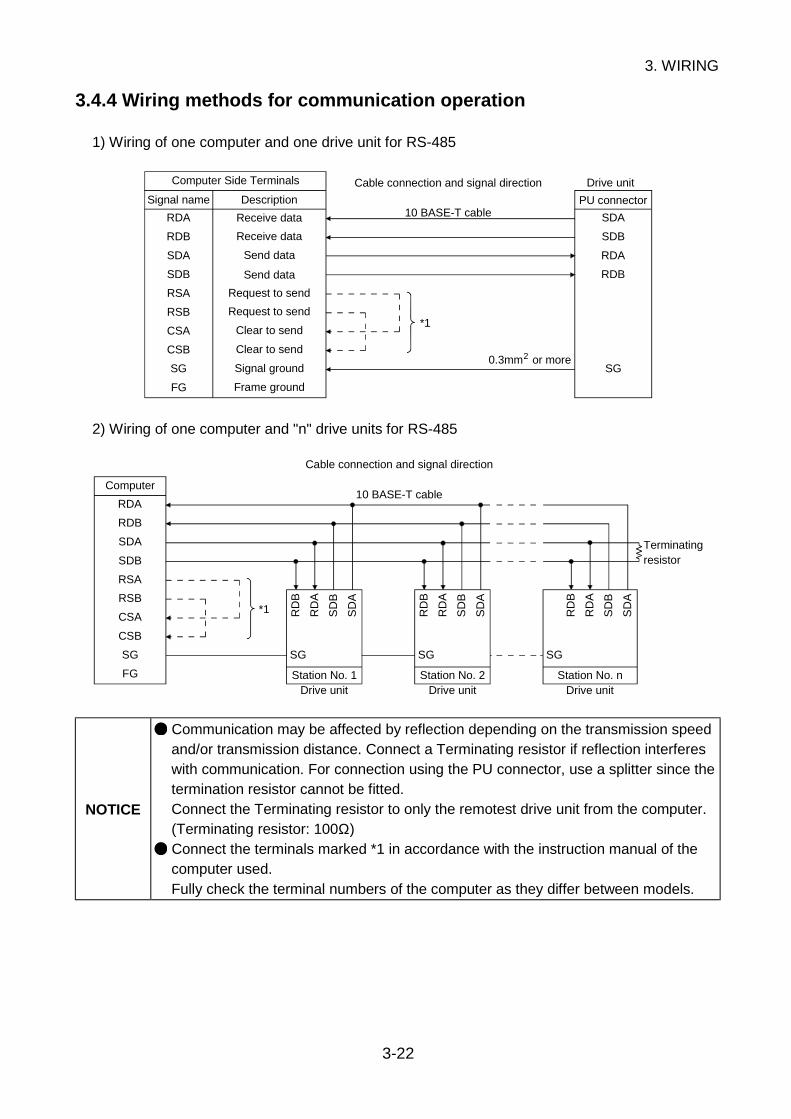
3.4.4 Wiring methods for communication operation
1) Wiring of one computer and one drive unit for RS-485
SDB
SDA
RDB
RDA
FG
SG
CSB
CSA
RSB
RSA
RDB
RDA
SDB
SDA
SG
Computer Side Terminals
Signal name Description
Receive data
Receive data
Send data
Send data
Request to send
Request to send
Clear to send
Clear to send
Signal ground
Frame ground
Cable connection and signal direction
10 BASE-T cablePU connector
0.3mm or more
Drive unit
*1
2
2) Wiring of one computer and "n" drive units for RS-485
SDB
SDA
RDB
RDA
FG
SG
CSB
CSA
RSB
RSA
SG
RD
B
RD
A
SD
B
SD
A
SG
RD
B
RD
A
SD
B
SD
A
SG
RD
B
RD
A
SD
B
SD
A
Computer
Cable connection and signal direction
10 BASE-T cable
Terminatingresistor
Station No. 1Drive unit
Station No. 2Drive unit
Station No. nDrive unit
*1
NOTICE
Communication may be affected by reflection depending on the transmission speedand/or transmission distance. Connect a Terminating resistor if reflection interfereswith communication. For connection using the PU connector, use a splitter since thetermination resistor cannot be fitted.Connect the Terminating resistor to only the remotest drive unit from the computer.(Terminating resistor: 100Ω) Connect the terminals marked *1 in accordance with the instruction manual of thecomputer used.Fully check the terminal numbers of the computer as they differ between models.
4. HOW TO USE THE OPERATION PANEL
4-1
1
2
3
4
5
6
7
8
4. HOW TO USE THE OPERATION PANEL
This chapter provides instructions on how to use the operation panel (FR-DU04) of the drive unit.
MEMO
For the way to use the FR-PU04 parameter unit, refer to the instruction manual ofthe FR-PU04 parameter unit. Note that when the FR-PU04 is used, there arerestrictions on some of the FR-PU04 functions.
Refer to: 4.4 Restrictions for Use of the FR-PU04
Contents of This Chapter Page
4.1 Part Names and Functions 4-2
4.2 Operation Modes 4-3
4.3 Operation Procedures 4-4
4.4 Restrictions for Use of the FR-PU04 4-8

4. HOW TO USE THE OPERATION PANEL
4-2
4.1 Part Names and Functions
FR-DU04HzAV
MON EXT PU
CONTROL PANEL
FWD
MODE
SET
REV FWD
STOPRESET
REV
Key operation section
Main indicator LED Unit indicator LEDs
Mode indicator LEDs
Name Function
Main indicator LED (4 digits)Indicates the speed, output current and other monitoredvalues and various function settings.
Hz A V
For speed (r/min), machine speed monitoring
For frequency monitoring
For current monitoring
Unit indicatorLEDs
: On: Off
For voltage monitoring
MON Lit in the monitor mode.
EXT PU
Indicate external operation mode.
Indicate PU operation mode, speed setting mode, orparameter setting mode.
Indicate external/PU combined operation mode 1, 2.
Indicate help mode.
REV FWD
Indicate forward rotation operation
Indicate reverse rotation operation
Mode indicatorLEDs
: On: Flicker: Off
Indicate stop
MODEUsed to select the monitor, speed setting, parameter setting,operation mode or help mode.
(UP/DOWN)
Used to change the speed setting, parameter number, setvalue or help item.Press to increase or to decrease.
SETUsed to confirm operation, e.g. determine the speed settingor parameter setting.
REV Used to start operation in the reverse rotation direction.
FWD Used to start operation in the forward rotation direction.
Key operationsection
STOP/RESETUsed to decelerate the running motor to a stop.Functions as an alarm reset key when the motor has stoppedwith an alarm indication.

4. HOW TO USE THE OPERATION PANEL
4-3
4
4.2 Operation Modes
The operation panel can be used to stop operation, set the speed, monitor the operationcommand/status, display an alarm, and copy the parameter values. Press the MODE key to displayeach mode in sequence.
Mode Description
Monitor modeUsed to display the speed, motor current or output voltage. Setting theparameter function enables another item to be displayed.
Refer to: Chapter 8, 8.7.1 Selection of operation panel display data
Speed settingmode
Used to enter the speed command from the operation panel.Displayed only in the PU operation mode or PU/external combined operationmode 1, 2.
Refer to: Chapter 5 Operation
Parametersetting mode
Used to set the parameter values.
Operation modeYou can select the external, PU or PU JOG operation. You can fix theoperation method by setting the parameter function.
Refer to: Pr. 79 [Section 8.2]
The help mode enables the following functions.
Alarm historyread
Used to read the last four alarms.The latest alarm is indicated by "." which follows thecharacter E. E. _ _0 appears to indicate no alarm.
Alarm historyclear
Used to clear all the alarm history.
Parameter clear
Used to initialize the parameter settings to the factorysettings.Pr. 75, Pr. 180 to Pr. 195, Pr. 900 to Pr. 905 and controlparameters are not initialized.You can disable parameter clear by setting the parameterfunction.
Refer to: Pr. 77 [Section 8.1]
All clearUsed to clear all the parameter settings and calibrationvalues to the factory settings.Pr. 71, Pr. 75, Pr. 80 and Pr. 188 are not initialized.
Help mode
User clear
Used to initialize the user-set parameter values. The otherparameters are initialized to the factory settings.Pr. 75, Pr. 180 to Pr. 195 and control parameters are notinitialized.
Refer to: Pr. 199 [Section 8.1]
Copy mode
You can copy the parameter settings to another drive unit.You can not copy them between the drive units whose capacities differ. If youhave copied them accidentally, perform the all clear function for the drive unit ofthe copy destination.Also, you cannot copy the parameter values to the drive unit which is not theMD-AX520 series. (E. rE4 model error appears.)

4. HOW TO USE THE OPERATION PANEL
4-4
4.3 Operation Procedures
(1) Monitor mode
MODE
SET
SET
SET
FR-DU04 CONTROL PANEL
Hz
MON EXT PU
AV
REV FWD
FR-DU04 CONTROL PANEL
Hz
MON EXT PU
AV
REV FWD
FR-DU04 CONTROL PANEL
Hz
MON EXT PU
AV
REV FWD
FR-DU04 CONTROL PANEL
Hz
MON EXT PU
AV
REV FWD
SET SET SETTo monitor mode
initial screen
Current monitor Voltage monitor Alarm monitor(Power-on screen)
Initial screenSpeed monitor
MEMO
To display the current or voltage monitor at power-on, press for more than 2s.
The alarm monitor screen appears only at an alarm stop.
Press for more than 2s on the alarm monitor screen to display alarms in sequence.
(2) Speed setting mode Setting example: Setting of speed to 1000r/min
MODE
MODE
FR-DU04 CONTROL PANEL
Hz
MON EXT PU
AV
REV FWD
FR-DU04 CONTROL PANEL
Hz
MON EXT PU
AV
REV FWD
FR-DU04 CONTROL PANEL
Hz
MON EXT PU
AV
REV FWD
FR-DU04 CONTROL PANEL
Hz
MON EXT PU
AV
REV FWD
SET
To parameter setting mode
Present settingInitial screen
Preset speed changingAppear alternately.
To monitor
mode initial
screen
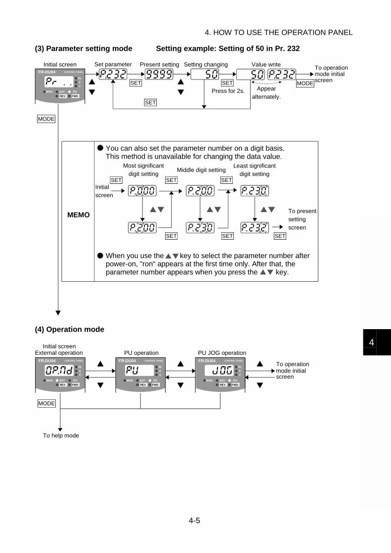
4. HOW TO USE THE OPERATION PANEL
4-5
4
(3) Parameter setting mode Setting example: Setting of 50 in Pr. 232
MODE
MODE
SET
SET SET SET
SET SET SET
FR-DU04 CONTROL PANEL
Hz
MON EXT PU
AV
REV FWD
SET SETAppear
alternately.
Initial screen Set parameter Present setting Setting changing Value write
screen
Press for 2s.
MEMO
You can also set the parameter number on a digit basis. This method is unavailable for changing the data value.
Initial
screen
Most significant
digit settingMiddle digit setting
Least significant
digit setting
To present
setting
screen
When you use the key to select the parameter number after power-on, "ron" appears at the first time only. After that, the parameter number appears when you press the key.
To operationmode initial
(4) Operation mode
MODE
FR-DU04 CONTROL PANEL
Hz
MON EXT PU
AV
REV FWD
FR-DU04 CONTROL PANEL
Hz
MON EXT PU
AV
REV FWD
FR-DU04 CONTROL PANEL
Hz
MON EXT PU
AV
REV FWD
To help mode
Initial screenExternal operation PU operation PU JOG operation
screen
To operationmode initial
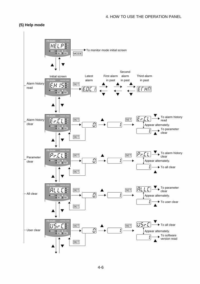
4. HOW TO USE THE OPERATION PANEL
4-6
(5) Help mode
SET
MODE
SET SET
SET
SET
SET
SET
SET
SET
SET
SET
SET
SET
FR-DU04 CONTROL PANEL
Hz
MON EXT PU
AV
REV FWD
FR-DU04 CONTROL PANEL
Hz
MON EXT PU
AV
REV FWD
FR-DU04 CONTROL PANEL
Hz
MON EXT PU
AV
REV FWD
FR-DU04 CONTROL PANEL
Hz
MON EXT PU
AV
REV FWD
FR-DU04 CONTROL PANEL
Hz
MON EXT PU
AV
REV FWD
FR-DU04 CONTROL PANEL
Hz
MON EXT PU
AV
REV FWD
To monitor mode initial screen
Alarm history
read
Initial screen Latest
alarm
First alarm
in past
Second
alarm
in past
Third alarm
in past
Alarm historyclear Appear alternately.
Parameter
clear Appear alternately.
To all clear
To parameter
To user clear
All clearAppear alternately.
User clear
To all clear
To software
Appear alternately.
To alarm historyread
To parameterclear
To alarm historyclear
clear
version read

4. HOW TO USE THE OPERATION PANEL
4-7
4
SET
FR-DU04 CONTROL PANEL
Hz
MON EXT PU
AV
REV FWD
Software
version read
Help mode initial screen
To user clear
Appear alternately.
To alarm history read
MEMO
Pressing SET on the alarm history display screen shows the speed, current andvoltage at alarm occurrence. (This function is invalid for the IPF alarm. "0"s appearfor all indications.) Any of the parameter clear, all clear and user clear operations can be performed inthe PU operation mode or PU/external combined operation mode 1, 2. "Err" flickersin the external operation mode.
(6) Parameter copy mode (Start operation from the initial screen of the parameter setting mode)1) Parameter read operation
MODESET
SETFR-DU04 CONTROL PANEL
Hz
MON EXT PU
AV
REV FWD
Initial screen
Press for 2s.To operation
mode initial
screenFlicker Completedwhen lit.
2) Parameter write operation
MODESET
SETFR-DU04 CONTROL PANEL
Hz
MON EXT PU
AV
REV FWD
Completed when
power-reset is
made after lit.
Initial screen
Press for 2s. To operation
mode initial
screenFlicker
3) Write parameter verify
MODESETFR-DU04 CONTROL PANEL
Hz
MON EXT PU
AV
REV FWD
Completedwhen lit.
Initial screen
Press for 2s. To operation
mode initial
screenFlicker
MEMO
When you have completed parameter write, always power "OFF" the drive unit onceto reset before starting operation. Restart operation from the beginning if the read error E. rE1 or write error E. rE2appears during operation. If a data discrepancy occurs during parameter verify, the corresponding parameternumber and "verify error (E. rE3)" appear alternately. If the preset speed or JOGspeed setting of the operation panel is discrepant, the "verify error (E. rE3)"appears. To ignore the error and continue verify, press the SET key. Copying cannot be done if "1" is set in Pr. 77 "parameter write disable selection" ofthe copy destination drive unit.
Refer to: Chapter 8, 8.1 Protection and Editing of the Parameters
4. HOW TO USE THE OPERATION PANEL
4-8
4.4 Restrictions for Use of the FR-PU04
When the FR-PU04 parameter unit (option) is used, some of the FR-PU04 functions areunavailable.
(1) Parameter unit display language• Data may be displayed in Japanese only. It cannot be changed to any other language.
(2) Parameter names and setting ranges• The parameter names (katakana characters) do not appear. (Except Pr. 900 to Pr. 905)• The parameter setting ranges do not appear.
(3) Function-by-function parameter setting feature• Invalid.
(4) Help function• The parameter list does not appear.• The parameter change list does not appear.• The troubleshooting function is unavailable. "The remedy screen for " "
appears but the corresponding parameter function does not exist.• Function " " appears only for the "RL, RM, RH, RT, AU, JOG, CS" contact input
terminals.

5. OPERATION
5-1
1
2
3
4
5
6
7
8
5. OPERATION
This chapter gives the basic operation methods of the drive unit.
CAUTION If the machine should become out of control, perform test operation after ensuringsafety. Start operation after performing test operation under light load at low speed toensure that operation is performed safely. Check that the machine has no damage. Securely set the parameter values to match the operating machine systemenvironment.
Contents of This Chapter Page
5.1 Power On 5-2
5.2 Parameter Setting 5-25.2.1 Setting of the operation mode parameter........................................... 5-25.2.2 Confirmation of the basic operation parameters................................. 5-2
5.3 Operation Examples 5-35.3.1 PU operation mode............................................................................ 5-35.3.2 External operation mode.................................................................... 5-45.3.3 External/PU combined operation mode 1........................................... 5-55.3.4 External/PU combined operation mode 2........................................... 5-65.3.5 Starting operation .............................................................................. 5-7
5. OPERATION
5-2
5.1 Power On
Switch power on after making sure that the unit has been installed and wired properly and that thestart signal is OFF.The LEDs and POWER lamp of the operation panel are lit.
NOTICE
If the LEDs do not come on, check the following:• There is no contact fault in the connection of the operation panel and the drive unit;• The jumper across the DC reactor connection terminals P/+-P1 is fitted properly; and• The jumper across the control circuit power supply terminals R1-S1 is fitted properly.
5.2 Parameter Setting
5.2.1 Setting of the operation mode parameter
Depending on the start signal (forward rotation command, reverse rotation command, stopcommand) and speed setting signal input method, you may need to set the parameter.Choose the used operation mode in Pr. 79 [Section 8.2].
5.2.2 Confirmation of the basic operation parameters
To meet various applications, a wealth of parameter functions are available for the drive unit. Thedrive unit is designed to perform simple variable-speed operation using the parameter values setbefore shipment from the factory. Depending on the specification conditions of the load (machine),however, some parameter values may need to be checked and changed.The parameters marked BASIC in the table of contents of Chapter 8 PARAMETER FUNCTIONSare the basic operation parameters whose values are recommended to be checked prior tooperation. Set them to values which match the specification conditions of the load.

5. OPERATION
5-3
5
5.3 Operation Examples
5.3.1 PU operation mode
(1) When performing operation by setting the running speed (1000r/min) with the (UP/DOWN) key
Step Operation Procedure (from Factory Setting)Display
(on Completion ofOperation)
1) When power is switched on, the "MON" mode indicatorLED of the operation panel is lit and the monitor screenappears.
FR-DU04 CONTROL PANEL
Hz
MON EXT PU
AV
REV FWD
1. Confirm theoperation mode.
2) Choose PU operation on the operation mode screenand set 1 in Pr. 79 [Section 8.2] in the parameter settingmode.(When Pr. 79=0, the drive unit is placed in the externaloperation mode at power-on. Therefore, you need tochange the external operation mode to the PUoperation mode every time power is switched on.)
Selecting the PU operation mode lights up the "PU"mode indicator LED of the operation panel.
FR-DU04 CONTROL PANEL
Hz
MON EXT PU
AV
REV FWD
FR-DU04 CONTROL PANEL
Hz
MON EXT PU
AV
REV FWD
1) Press the MODE key to display the speed setting modescreen.2. Set the running
speed. 2) Set the running speed with the key.
FR-DU04 CONTROL PANEL
Hz
MON EXT PU
AV
REV FWD
1) Press the FWD key to start the motor running in theforward rotation direction or the REV key to start itrunning in the reverse rotation direction, increasing thespeed in accordance with the preset acceleration time.
2) The display screen changes automatically from thespeed setting mode screen to the monitor mode screen.The "FWD" mode indicator LED flickers to indicateforward rotation, or the "REV" mode indicator LEDflickers to indicate reverse rotation.
3. Enter the startsignal.
3) Acceleration is complete when the main indicator LEDshows the preset speed.
FR-DU04 CONTROL PANEL
Hz
MON EXT PU
AV
REV FWD
FR-DU04 CONTROL PANEL
Hz
MON EXT PU
AV
REV FWD
4. Enter the stopsignal.
1) Press the STOP/RESET key to decelerate the motor toa stop in accordance with the preset deceleration time.After stopping, the "FWD" or "REV" mode indicator LEDgoes off.
FR-DU04 CONTROL PANEL
Hz
MON EXT PU
AV
REV FWD
(2) When performing JOG operation by operating the keys of the operation panelRefer to: Chapter 8, 8.6.1 JOG operation

5. OPERATION
5-4
5.3.2 External operation mode
(1) When performing operation using the analog speed command (voltage input)
Step Operation Procedure (from Factory Setting)Display
(on Completion ofOperation)
1) When power is switched on, the "MON" mode indicatorLED of the operation panel is lit and the monitor screenappears.
FR-DU04 CONTROL PANEL
Hz
MON EXT PU
AV
REV FWD
1. Confirm theoperation mode.
2) Choose PU operation on the operation mode screenand set 0 or 2 in Pr. 79 [Section 8.2] in the parametersetting mode.
Selecting the external operation mode lights up the"EXT" mode indicator LED of the operation panel.
FR-DU04 CONTROL PANEL
Hz
MON EXT PU
AV
REV FWD
FR-DU04 CONTROL PANEL
Hz
MON EXT PU
AV
REV FWD
1) Turn on the start signal connected to the terminal STF(or STR).2. Enter the start
signal. 2) The "FWD" (or "REV") mode indicator LED flickers.
FR-DU04 CONTROL PANEL
Hz
MON EXT PU
AV
REV FWD
1) Entering the speed setting signal to the terminal 2 runsthe motor.3. Enter the
running speedsignal.
2) The speed rises in proportion to the increase of thespeed setting signal.
FR-DU04 CONTROL PANEL
Hz
MON EXT PU
AV
REV FWD
4. Enter the stopsignal.
1) Decreasing the speed setting signal of the terminal 2reduces the speed.
2) After the speed reaches zero, turning off the start signalextinguishes the "FWD" or "REV" mode indicator LED.
FR-DU04 CONTROL PANEL
Hz
MON EXT PU
AV
REV FWD
MEMO
For the analog command, the motor speed varies at the change ratio (slope) of theinput signal, but it cannot vary faster than the preset acceleration or decelerationtime. To control the speed in response to the input signal's change ratio, set theacceleration/deceleration time to "0".
You may turn the start signal on/off to start operation after entering the speedsetting signal. In this case, the motor speed rises or falls in accordance with thepreset acceleration/deceleration time.
Use Pr. 902 to 905 [Section 8.3.1] to change the relationship between the analogspeed command and motor speed.
(2) When performing JOG operation using the terminal STF, STRRefer to: Chapter 8, 8.6.1 JOG operation
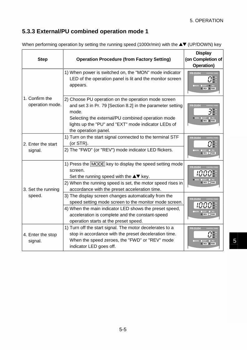
5. OPERATION
5-5
5
5.3.3 External/PU combined operation mode 1
When performing operation by setting the running speed (1000r/min) with the (UP/DOWN) key
Step Operation Procedure (from Factory Setting)Display
(on Completion ofOperation)
1) When power is switched on, the "MON" mode indicatorLED of the operation panel is lit and the monitor screenappears.
FR-DU04 CONTROL PANEL
Hz
MON EXT PU
AV
REV FWD
1. Confirm theoperation mode.
2) Choose PU operation on the operation mode screenand set 3 in Pr. 79 [Section 8.2] in the parameter settingmode.Selecting the external/PU combined operation modelights up the "PU" and "EXT" mode indicator LEDs ofthe operation panel.
FR-DU04 CONTROL PANEL
Hz
MON EXT PU
AV
REV FWD
1) Turn on the start signal connected to the terminal STF(or STR).2. Enter the start
signal. 2) The "FWD" (or "REV") mode indicator LED flickers.
FR-DU04 CONTROL PANEL
Hz
MON EXT PU
AV
REV FWD
1) Press the MODE key to display the speed setting modescreen.Set the running speed with the key.
2) When the running speed is set, the motor speed rises inaccordance with the preset acceleration time.
FR-DU04 CONTROL PANEL
Hz
MON EXT PU
AV
REV FWD
3) The display screen changes automatically from thespeed setting mode screen to the monitor mode screen.
3. Set the runningspeed.
4) When the main indicator LED shows the preset speed,acceleration is complete and the constant-speedoperation starts at the preset speed.
FR-DU04 CONTROL PANEL
Hz
MON EXT PU
AV
REV FWD
4. Enter the stopsignal.
1) Turn off the start signal. The motor decelerates to astop in accordance with the preset deceleration time.When the speed zeroes, the "FWD" or "REV" modeindicator LED goes off.
FR-DU04 CONTROL PANEL
Hz
MON EXT PU
AV
REV FWD

5. OPERATION
5-6
5.3.4 External/PU combined operation mode 2
When performing operation using the analog speed command (voltage input)
Step Operation Procedure (from Factory Setting)Display
(on Completion ofOperation)
1) When power is switched on, the "MON" mode indicatorLED of the operation panel is lit and the monitor screenappears.
FR-DU04 CONTROL PANEL
Hz
MON EXT PU
AV
REV FWD
1. Confirm theoperation mode.
2) Choose PU operation on the operation mode screenand set 4 in Pr. 79 [Section 8.2] in the parameter settingmode.Selecting the external/PU combined operation modelights up the "PU" and "EXT" mode indicator LEDs ofthe operation panel.
FR-DU04 CONTROL PANEL
Hz
MON EXT PU
AV
REV FWD
2. Enter the startsignal.
1) Pressing the FWD key flickers the "FWD" operationstatus indicator LED.Pressing the REV key flickers the "REV" operationstatus indicator LED.
FR-DU04 CONTROL PANEL
Hz
MON EXT PU
AV
REV FWD
3. Set the runningspeed.
1) Entering the speed setting signal to the terminal 2 runsthe motor. The speed rises in proportion to the increaseof the speed setting signal.
FR-DU04 CONTROL PANEL
Hz
MON EXT PU
AV
REV FWD
4. Enter the stopsignal.
1) Press the STOP/RESET key to decelerate the motor toa stop in accordance with the preset deceleration time.After a stop, the "FWD" or "REV" mode indicator LEDgoes off.
FR-DU04 CONTROL PANEL
Hz
MON EXT PU
AV
REV FWD
MEMO
For the analog command, the motor speed varies at the change ratio (slope) of theinput signal, but it cannot vary faster than the preset acceleration or decelerationtime. To control the speed in response to the input signal's change ratio, set theacceleration/deceleration time to "0".
You may turn the start signal on/off to start operation after entering the speedsetting signal. In this case, the motor speed rises or falls in accordance with thepreset acceleration/deceleration time.
Use Pr. 902 to 905 [Section 8.3.1] to change the relationship between the analogspeed command and motor speed.

5. OPERATION
5-7
5
5.3.5 Starting operation
The drive unit detects the magnetic pole of the motor at every start. The magnetic pole detectiontime is approx. 0.1s (85ms±15ms) after the start signal and speed signal are input. During thisperiod, the motor remains stopped and starts running after magnetic pole detection is finished.
When inputting the speed command from the operation panel or as a contact signal
ON
ON
Approx. 0.1s
Start signal
Speed command
Motor speed
RUN signal5 to 35ms
When inputting the speed command as an analog signal
100r/min
ON
5 to 35ms
ON
Approx. 0.1s
Start signal
Speed command
Motor speed
RUN signal
MEMO
When the start signal is entered after the input of the speed command, the motorstarts running approx. 0.1s after the input of the start signal.
When the analog signal is used to give the speed command, the motor startsrunning approx. 0.1s after the speed command has reached the value equivalent to100r/min (value set in Pr. 13).
For forward/reverse rotation operation, there is an about 0.1s to 3.0s stopdepending on the operating conditions.
NOTICE
When restarting the motor after decelerating it to a stop, start the motor afterensuring that it has stopped. If you start the motor that has not yet come to acomplete stop, sufficient torque may not be provided. Especially when the loadtorque (friction torque) is small and the load inertia moment is large, the motor willrun slightly even after the voltage braking operation has stopped. Therefore, restartthe motor after making sure that it has stopped completely.
Refer to: Chapter 8, 8.5.4 Stopping operation
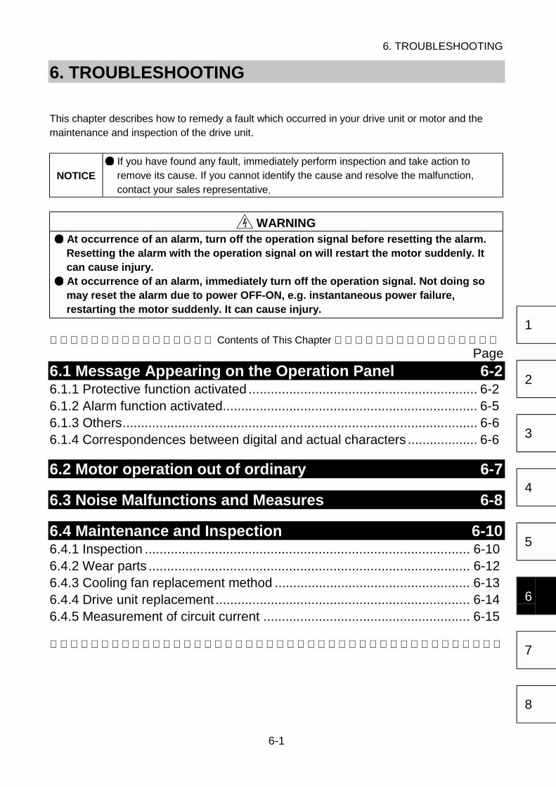
6. TROUBLESHOOTING
6-1
1
2
3
4
5
6
7
8
6. TROUBLESHOOTING
This chapter describes how to remedy a fault which occurred in your drive unit or motor and themaintenance and inspection of the drive unit.
NOTICE If you have found any fault, immediately perform inspection and take action toremove its cause. If you cannot identify the cause and resolve the malfunction,contact your sales representative.
WARNING At occurrence of an alarm, turn off the operation signal before resetting the alarm.Resetting the alarm with the operation signal on will restart the motor suddenly. Itcan cause injury. At occurrence of an alarm, immediately turn off the operation signal. Not doing somay reset the alarm due to power OFF-ON, e.g. instantaneous power failure,restarting the motor suddenly. It can cause injury.
Contents of This Chapter Page
6.1 Message Appearing on the Operation Panel 6-26.1.1 Protective function activated .............................................................. 6-26.1.2 Alarm function activated..................................................................... 6-56.1.3 Others................................................................................................ 6-66.1.4 Correspondences between digital and actual characters ................... 6-6
6.2 Motor operation out of ordinary 6-7
6.3 Noise Malfunctions and Measures 6-8
6.4 Maintenance and Inspection 6-106.4.1 Inspection ........................................................................................ 6-106.4.2 Wear parts ....................................................................................... 6-126.4.3 Cooling fan replacement method ..................................................... 6-136.4.4 Drive unit replacement ..................................................................... 6-146.4.5 Measurement of circuit current ........................................................ 6-15
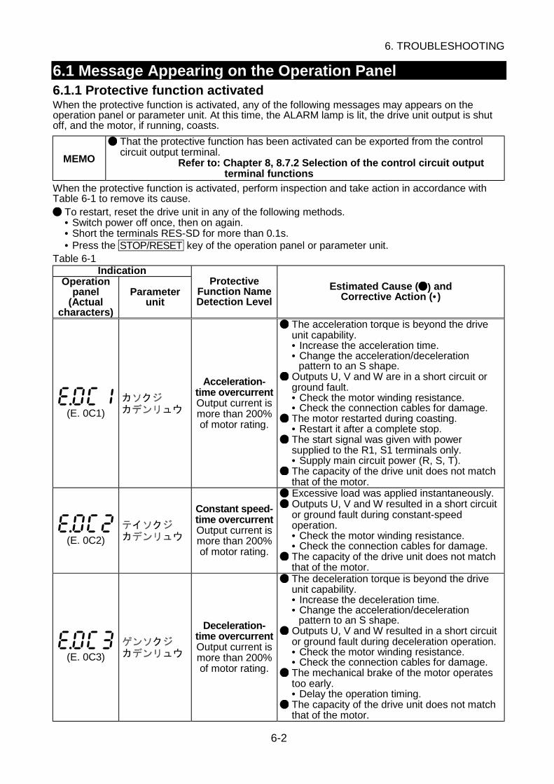
6. TROUBLESHOOTING
6-2
6.1 Message Appearing on the Operation Panel6.1.1 Protective function activatedWhen the protective function is activated, any of the following messages may appears on theoperation panel or parameter unit. At this time, the ALARM lamp is lit, the drive unit output is shutoff, and the motor, if running, coasts.
MEMO
That the protective function has been activated can be exported from the controlcircuit output terminal.
Refer to: Chapter 8, 8.7.2 Selection of the control circuit outputterminal functions
When the protective function is activated, perform inspection and take action in accordance withTable 6-1 to remove its cause.
To restart, reset the drive unit in any of the following methods.• Switch power off once, then on again.• Short the terminals RES-SD for more than 0.1s.• Press the STOP/RESET key of the operation panel or parameter unit.
Table 6-1Indication
Operationpanel
(Actualcharacters)
Parameterunit
ProtectiveFunction NameDetection Level
Estimated Cause ( ) andCorrective Action (• )
(E. 0C1)
Acceleration-time overcurrentOutput current ismore than 200%of motor rating.
The acceleration torque is beyond the driveunit capability.• Increase the acceleration time.• Change the acceleration/deceleration
pattern to an S shape. Outputs U, V and W are in a short circuit orground fault.• Check the motor winding resistance.• Check the connection cables for damage. The motor restarted during coasting.• Restart it after a complete stop. The start signal was given with powersupplied to the R1, S1 terminals only.• Supply main circuit power (R, S, T). The capacity of the drive unit does not matchthat of the motor.
(E. 0C2)
Constant speed-time overcurrentOutput current ismore than 200%of motor rating.
Excessive load was applied instantaneously. Outputs U, V and W resulted in a short circuitor ground fault during constant-speedoperation.• Check the motor winding resistance.• Check the connection cables for damage. The capacity of the drive unit does not matchthat of the motor.
(E. 0C3)
Deceleration-time overcurrentOutput current ismore than 200%of motor rating.
The deceleration torque is beyond the driveunit capability.• Increase the deceleration time.• Change the acceleration/deceleration
pattern to an S shape. Outputs U, V and W resulted in a short circuitor ground fault during deceleration operation.• Check the motor winding resistance.• Check the connection cables for damage. The mechanical brake of the motor operatestoo early.• Delay the operation timing. The capacity of the drive unit does not matchthat of the motor.
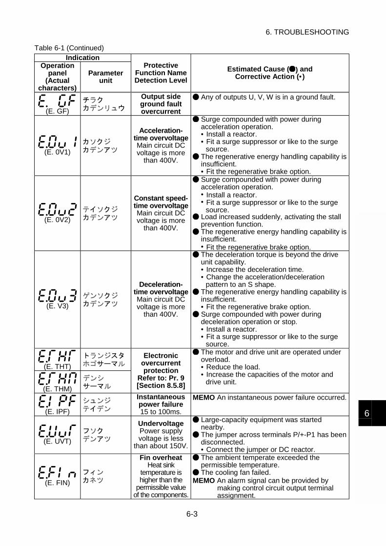
6. TROUBLESHOOTING
6-3
6
Table 6-1 (Continued)Indication
Operationpanel
(Actualcharacters)
Parameterunit
ProtectiveFunction NameDetection Level
Estimated Cause ( ) andCorrective Action (• )
(E. GF)
Output sideground faultovercurrent
Any of outputs U, V, W is in a ground fault.
(E. 0V1)
Acceleration-time overvoltageMain circuit DCvoltage is more
than 400V.
Surge compounded with power duringacceleration operation.• Install a reactor.• Fit a surge suppressor or like to the surge
source. The regenerative energy handling capability isinsufficient.• Fit the regenerative brake option.
(E. 0V2)
Constant speed-time overvoltageMain circuit DCvoltage is more
than 400V.
Surge compounded with power duringacceleration operation.• Install a reactor.• Fit a surge suppressor or like to the surge
source. Load increased suddenly, activating the stallprevention function. The regenerative energy handling capability isinsufficient.• Fit the regenerative brake option.
(E. V3)
Deceleration-time overvoltageMain circuit DCvoltage is more
than 400V.
The deceleration torque is beyond the driveunit capability.• Increase the deceleration time.• Change the acceleration/deceleration
pattern to an S shape. The regenerative energy handling capability isinsufficient.• Fit the regenerative brake option. Surge compounded with power duringdeceleration operation or stop.• Install a reactor.• Fit a surge suppressor or like to the surge
source.
(E. THT)
(E. THM)
Electronicovercurrentprotection
Refer to: Pr. 9[Section 8.5.8]
The motor and drive unit are operated underoverload.• Reduce the load.• Increase the capacities of the motor and
drive unit.
(E. IPF)
Instantaneouspower failure15 to 100ms.
MEMO An instantaneous power failure occurred.
(E. UVT)
UndervoltagePower supplyvoltage is less
than about 150V.
Large-capacity equipment was startednearby. The jumper across terminals P/+-P1 has beendisconnected.• Connect the jumper or DC reactor.
(E. FIN)
Fin overheatHeat sink
temperature ishigher than the
permissible valueof the components.
The ambient temperate exceeded thepermissible temperature. The cooling fan failed.
MEMO An alarm signal can be provided bymaking control circuit output terminalassignment.
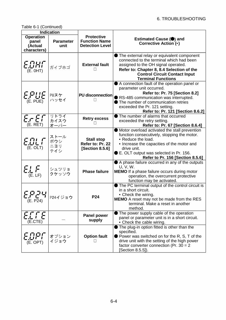
6. TROUBLESHOOTING
6-4
Table 6-1 (Continued)Indication
Operationpanel
(Actualcharacters)
Parameterunit
ProtectiveFunction NameDetection Level
Estimated Cause ( ) andCorrective Action (• )
(E. 0HT)
External fault
The external relay or equivalent componentconnected to the terminal which had beenassigned to the OH signal operated.Refer to: Chapter 8, 8.4 Selection of the
Control Circuit Contact InputTerminal Functions
(E. PUE)
PU disconnection
A connection fault of the operation panel orparameter unit occurred.
Refer to: Pr. 75 [Section 8.2] RS-485 communication was interrupted. The number of communication retriesexceeded the Pr. 121 setting.
Refer to: Pr. 121 [Section 8.6.2]
(E. RET)
Retry excess
The number of alarms that occurredexceeded the retry setting.
Refer to: Pr. 67 [Section 8.6.4]
(E. OLT)
Stall stopRefer to: Pr. 22[Section 8.5.6]
Motor overload activated the stall preventionfunction consecutively, stopping the motor.• Reduce the load.• Increase the capacities of the motor and
drive unit. E. OLT output was selected in Pr. 156.
Refer to Pr. 156 [Section 8.5.6]
(E. LF)Phase failure
A phase failure occurred in any of the outputsU, V, W.
MEMO If a phase failure occurs during motoroperation, the overcurrent protectivefunction may be activated.
(E. P24)P24
The PC terminal output of the control circuit isin a short circuit.• Check the wiring.
MEMO A reset may not be made from the RESterminal. Make a reset in anothermethod.
(E.CTE)
Panel powersupply
The power supply cable of the operationpanel or parameter unit is in a short circuit.• Check the cable wiring.
(E. OPT)
Option fault
The plug-in option fitted is other than thespecified. Power was switched on for the R, S, T of thedrive unit with the setting of the high powerfactor converter connection (Pr. 30 = 2[Section 8.5.5]).

6. TROUBLESHOOTING
6-5
6
If any of the messages in Table 6-2 appears, the drive unit is assumed to have failed. If the samemessage reappears after an alarm reset, immediately replace the drive unit.
Table 6-2Indication
Operationpanel
(Actualcharacters)
Parameterunit
ProtectiveFunction NameDetection Level
Estimated Cause ( ) andCorrective Action (• )
(E. CPU)
(E. 6)
(E. 7)
CPU fault
The CPU malfunctioned. The CPU failed.
(E. PE)
Storage devicefault
The storage device failed.
(E. BE)Brake circuit fault
The regenerative brake circuit failed.• If E. BE reappears after a reset, immediately
switch power off.Leaving power on will overheat the brakeresistor.
6.1.2 Alarm function activated
If the alarm function is activated during motor operation, any of the displays in Table 6-3 is providedon the operation panel or parameter unit.If you ignore the alarm message and continue operation, the fault detection function is activated,leading to an operation stop. When you noticed that the alarm function had been activated,immediately remove its cause.
MEMO That the alarm function has been activated can be exported as an alarm signal.
Refer to: Chapter 8, 8.7.2 Selection of the control circuit outputterminal functions
Table 6-3Indication
Operationpanel
(Actualcharacters)
Parameterunit
Protective Function NameDetection Level Related Protective Function
(OL)
Overload 1Pr. 22 setting [Section 8.5.6]
Acceleration-time overcurrent,constant speed-timeovercurrent, deceleration-timeovercurrent, stall stop
(oL)
Overload 2Main circuit DC voltage more
than 390VDeceleration-time overvoltage
(RB)
Brake dutyMore than 85% of the permissible
valueDeceleration-time overvoltage
(TH)
Motor overheatMore than 85% of the electronic
overcurrent protection level
Electronic overcurrentprotection
(FN)
Fan failureCooling fan fault
Refer to: Pr. 244 [Section 8.5.8]Fin overheat

6. TROUBLESHOOTING
6-6
6.1.3 Others
Table 6-4Indication
Operationpanel
(Actualcharacters)
Parameterunit
ProtectiveFunction NameDetection Level
Estimated Cause ( ) andCorrective Action (• )
(Err)Operation error
Parameter changing operation was performedduring external operation. The value that was set is outside theparameter setting range. The RES signal remains ON. The operation panel is in a connection fault.• Check the fitting status.
MEMO An operation error does not activate therelay contact output.
(PS)
Emergency stopoperation
The STOP/RESET key of the operation panelor parameter unit was pressed to make a stopduring external operation.
MEMO A reset cannot be made in the normalmethod.
Refer to: Pr. 75 [Section 8.2]
(E. rE4)Copy error
Parameters were copied to a different model.Refer to: Chapter 4, 4.2 Operation Modes
6.1.4 Correspondences between digital and actual characters
There are the following correspondences between the actual alphanumeric characters and thedigital characters displayed on the operation panel.
Actual Digital Actual Digital Actual Digital
0
1
2
3
4
5
6
7
8
9
A
B
C
E
F
G
H
I
J
L
D
M
N
O
o
P
T
U
V
r
-
S
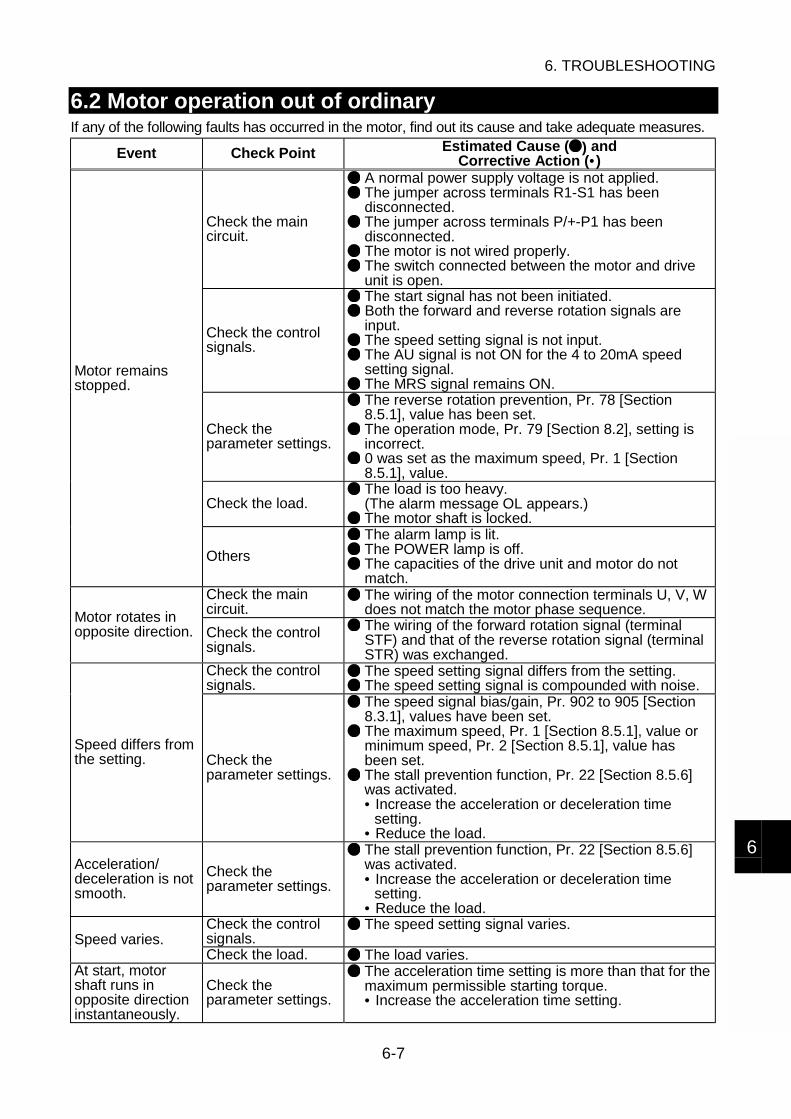
6. TROUBLESHOOTING
6-7
6
6.2 Motor operation out of ordinaryIf any of the following faults has occurred in the motor, find out its cause and take adequate measures.
Event Check Point Estimated Cause ( ) andCorrective Action (• )
Check the maincircuit.
A normal power supply voltage is not applied. The jumper across terminals R1-S1 has beendisconnected. The jumper across terminals P/+-P1 has beendisconnected. The motor is not wired properly. The switch connected between the motor and driveunit is open.
Check the controlsignals.
The start signal has not been initiated. Both the forward and reverse rotation signals areinput. The speed setting signal is not input. The AU signal is not ON for the 4 to 20mA speedsetting signal. The MRS signal remains ON.
Check theparameter settings.
The reverse rotation prevention, Pr. 78 [Section8.5.1], value has been set. The operation mode, Pr. 79 [Section 8.2], setting isincorrect. 0 was set as the maximum speed, Pr. 1 [Section8.5.1], value.
Check the load. The load is too heavy.(The alarm message OL appears.) The motor shaft is locked.
Motor remainsstopped.
Others The alarm lamp is lit. The POWER lamp is off. The capacities of the drive unit and motor do notmatch.
Check the maincircuit.
The wiring of the motor connection terminals U, V, Wdoes not match the motor phase sequence.Motor rotates in
opposite direction. Check the controlsignals.
The wiring of the forward rotation signal (terminalSTF) and that of the reverse rotation signal (terminalSTR) was exchanged.
Check the controlsignals.
The speed setting signal differs from the setting. The speed setting signal is compounded with noise.
Speed differs fromthe setting. Check the
parameter settings.
The speed signal bias/gain, Pr. 902 to 905 [Section8.3.1], values have been set. The maximum speed, Pr. 1 [Section 8.5.1], value orminimum speed, Pr. 2 [Section 8.5.1], value hasbeen set. The stall prevention function, Pr. 22 [Section 8.5.6]was activated.• Increase the acceleration or deceleration time
setting.• Reduce the load.
Acceleration/deceleration is notsmooth.
Check theparameter settings.
The stall prevention function, Pr. 22 [Section 8.5.6]was activated.• Increase the acceleration or deceleration time
setting.• Reduce the load.
Check the controlsignals.
The speed setting signal varies.Speed varies.
Check the load. The load varies.At start, motorshaft runs inopposite directioninstantaneously.
Check theparameter settings.
The acceleration time setting is more than that for themaximum permissible starting torque.• Increase the acceleration time setting.
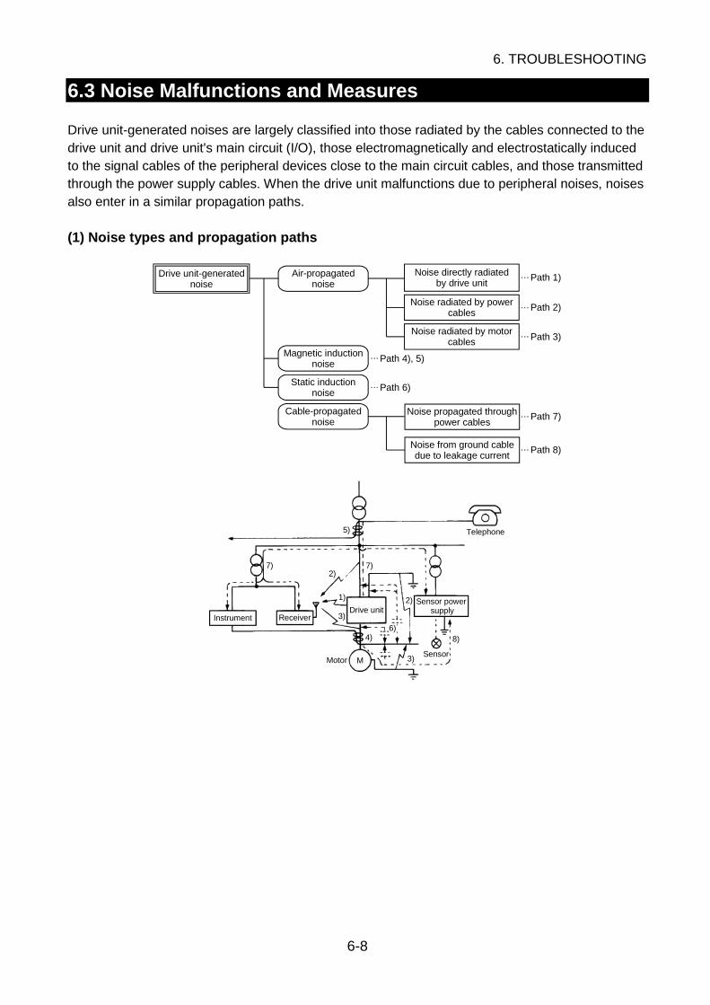
6. TROUBLESHOOTING
6-8
6.3 Noise Malfunctions and Measures
Drive unit-generated noises are largely classified into those radiated by the cables connected to thedrive unit and drive unit's main circuit (I/O), those electromagnetically and electrostatically inducedto the signal cables of the peripheral devices close to the main circuit cables, and those transmittedthrough the power supply cables. When the drive unit malfunctions due to peripheral noises, noisesalso enter in a similar propagation paths.
(1) Noise types and propagation paths
Path 8)
Drive unit-generatednoise
Air-propagatednoise
Magnetic inductionnoise
Static inductionnoise
Cable-propagatednoise
Path 4), 5)
Path 6)
Noise directly radiatedby drive unit
Noise radiated by powercables
Noise radiated by motorcables
Noise propagated throughpower cables
Noise from ground cabledue to leakage current
Path 1)
Path 2)
Path 3)
Path 7)
M
5)
7)2)
1)
3)
4)6)
2)
3)
7)
8)
Telephone
Instrument ReceiverDrive unit
MotorSensor
Sensor powersupply

6. TROUBLESHOOTING
6-9
6
(2) Specific measures
Take the following measures against anticipated noise propagation paths. For the necessity of themeasures, refer to the levels (estimated values) of the expected effects.
: Large effect, : With effect, : Small effect, : Without effectNoise Propagation Paths
Air-propagated noiseCable-
propagatednoise
Pla
ce MeasuresRadiatedby drive
unit
Radiatedby power
cables
Radiatedby motorcables
Magneticinduction
noise
Staticinduction
noise Throughpowercables
Fromgroundcable
Uni
t Decrease the motor toneselection (Pr. 72) setting.
Install the FR-BIF radionoise filter. Install the FR-BSF01 orFR-BLF line noise filter. Run the power cables in ametal conduit or useshielded cables.
Install an insulating transformeror noise cutting transformer.
AC
pow
er
supply
sid
e
Separate the power supply line. Install the FR-BSF01 orFR-BLF line noise filter. Run the motor cables in ametal conduit or useshielded cables.
Moto
r si
de
Use a 4-core cable as the motorpower cable and use one of itswires as a ground wire.
Use shielded cables as thesignal input cables.
Use twisted shielded cablesas the speed input cables.
Contr
ol c
ircu
it si
de
Insert commerciallyavailable ferrite cores intothe speed input cables.
Use twisted shielded cables asthe signal cables. Connect theshield sheath to the commonof the mating equipment.
Do not run cables in parallelwith the drive unit power cableor bundle them together.
Install the mating equipmentas far away as possible fromthe drive unit and power cable.
Provide a shielding platebetween the matingequipment and the driveunit/power cable.
Insert commercially availableferrite cores into the speedinput cables and like.
Matin
g e
quip
ment
side
Decrease the outputimpedance of the speedsignal output circuit.
6. TROUBLESHOOTING
6-10
6.4 Maintenance and Inspection
WARNING When performing inspection by removing the front cover or the like, switch poweroff, wait 10 or more minutes, then check that the voltage across the DC terminalsP/+-N/- is less than 30VDC with a tester or like before starting inspection. Not doingso can cause an electric shock. Any person who is involved in inspection should be fully competent to do the work.Otherwise, an electric shock can occur. Do not disassemble or repair the unit.
6.4.1 Inspection
(1) Daily inspectionDuring operation and power-on, visually check for the following faults without removing the coverand like.
1) Faulty motor operation2) Improper installation environment (ambient temperature, humidity, dust, dirt, etc.)3) Unusual noise, unusual vibration, foul odor, etc.4) Overheat trace, discoloration, etc.5) Improper cooling fan rotation6) Improper on/off of lamps, LEDs and others7) Improper meter indications
NOTICE
Always use the drive unit in a clean status.• When cleaning, always switch power off and gently wipe dirty areas with a soft
cloth immersed in neutral detergent or ethanol. Do not use detergent or the like toclean the display section of the operation panel or parameter unit.
• When cleaning, do not use solvent, e.g. acetone, benzene, toluene or alcohol, asthey will cause the drive unit surface paint to peel off.
(2) Periodic inspectionAfter operation has stopped, switch power off, remove the front cover, and perform periodicinspection referring to Table 6-5 Periodic Inspection List.

6. TROUBLESHOOTING
6-11
6
Table 6-5 Periodic Inspection List
Area ofInspection
Inspection Items Methods Criteria
Surroundingenvironment
1) Check ambient temperature,humidity, vibration, ambience (fordust, dirt, gas, oil mist, waterdrops, etc.)
2) Check for tools, foreign matterand dangerous articles in theperiphery.
1) Measure visually orwith instruments.• Thermometer• Hygrometer• Recorder
2) Visual check.
1) Standardspecificationvalues must besatisfied.
2) Must not be leftunremoved.
Overall unitCheck for unusual vibration andunusual noise.
Visual and auditorychecks.
No fault.
General
1) Check for loose screws and bolts.2) Check parts and members for
deformation, crack, damage, anddiscoloration caused by overheator deterioration.
3) Check for contamination andsticking dust and dirt.
1) Retighten.2), 3) Visual check.
1), 2), 3) No fault.
Conductors,cables
1) Check conductors fordiscoloration and distortioncaused by overheat.
2) Check cable sheaths forbreakage and discoloration.
1), 2) Visual check. 1), 2) No fault.
Terminalblock
Check for damage. Visual check. No fault.
Ma
in c
ircuit
ResistorCheck for foul odor and insulationcrack due to overheat.
Olfactory, visualchecks.
No fault.
Contr
ol c
ircu
it
Controlprintedcircuits,connectors
1) Check for loose screws, bolts andconnectors.
2) Check for unusual odor anddiscoloration.
3) Check for crack, damage,deformation, and rust.
4) Check capacitor for liquid leakageand traces of deformation.
1) Retighten.2) Olfactory, visual
checks.3), 4) Visual check.
1), 2), 3), 4) No fault.
Cooling fan1) Check for sticking foreign matter.2) Check for loose connection.
1) Hand turn.2) Visual check
1) Smooth turn.2) No fault.
Coolin
g s
yste
m
Ventilationpath
Check for clogged heat sink,suction/exhaust ports, and stickingforeign matter.
Visual check. No fault.
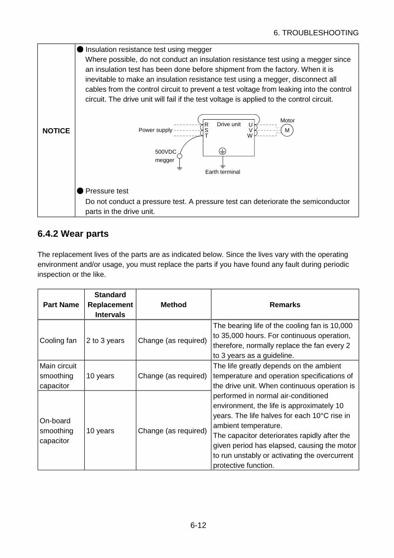
6. TROUBLESHOOTING
6-12
NOTICE
Insulation resistance test using meggerWhere possible, do not conduct an insulation resistance test using a megger sincean insulation test has been done before shipment from the factory. When it isinevitable to make an insulation resistance test using a megger, disconnect allcables from the control circuit to prevent a test voltage from leaking into the controlcircuit. The drive unit will fail if the test voltage is applied to the control circuit.
RST
UV
WM
Motor
Power supply
500VDC
megger
Drive unit
Earth terminal
Pressure test
Do not conduct a pressure test. A pressure test can deteriorate the semiconductorparts in the drive unit.
6.4.2 Wear parts
The replacement lives of the parts are as indicated below. Since the lives vary with the operatingenvironment and/or usage, you must replace the parts if you have found any fault during periodicinspection or the like.
Part NameStandard
ReplacementIntervals
Method Remarks
Cooling fan 2 to 3 years Change (as required)
The bearing life of the cooling fan is 10,000to 35,000 hours. For continuous operation,therefore, normally replace the fan every 2to 3 years as a guideline.
Main circuitsmoothingcapacitor
10 years Change (as required)
On-boardsmoothingcapacitor
10 years Change (as required)
The life greatly depends on the ambienttemperature and operation specifications ofthe drive unit. When continuous operation isperformed in normal air-conditionedenvironment, the life is approximately 10years. The life halves for each 10°C rise inambient temperature.The capacitor deteriorates rapidly after thegiven period has elapsed, causing the motorto run unstably or activating the overcurrentprotective function.

6. TROUBLESHOOTING
6-13
6
6.4.3 Cooling fan replacement method
Removal1) Remove the cooling fan cover.
Push the cover in the direction of arrows and pull it down.2) Unplug the cooling fan connector.3) Remove the cooling fan from the cooling fan cover.
The cooling fan is secured by the latches.
Reinstallation1) After confirming the orientation of the fan, reinstall the fan to the cover so that the arrow on
the left of "AIR FLOW" faces in the opposite direction of the fan cover.Note: The wrong direction of air flow can shorten the drive unit life.
2) Plug the connector.3) Reinstall the fan cover to the drive unit.
Use care to avoid the leads being caught between the chassis and cover.

6. TROUBLESHOOTING
6-14
6.4.4 Drive unit replacement
The drive unit can be changed with the control circuit wiring kept connected. Before replacement,remove the screws in the wiring cover of the drive unit.
1) Remove the mounting screws in both ends of the control circuit terminal block.2) With both hands, pull down the terminal block from the back of the control circuit terminals.
3) When installing the terminal block to a new drive unit, be careful not to bend the pins of thecontrol circuit terminal block connector.
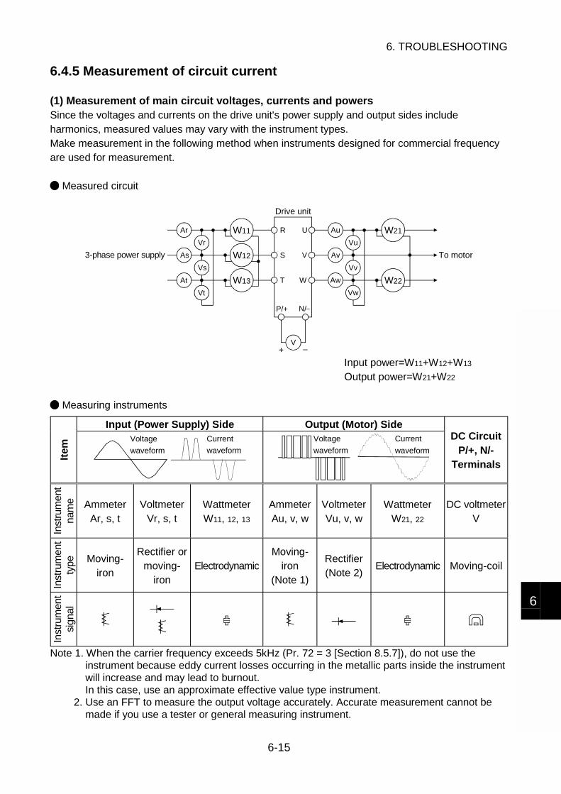
6. TROUBLESHOOTING
6-15
6
6.4.5 Measurement of circuit current
(1) Measurement of main circuit voltages, currents and powersSince the voltages and currents on the drive unit's power supply and output sides includeharmonics, measured values may vary with the instrument types.Make measurement in the following method when instruments designed for commercial frequencyare used for measurement.
Measured circuit
Ar
As
At
Vr
Vs
Vt
W11
W12
W13
Au
Av
Aw
Vu
Vv
Vw
W21
W22
V
R
S
T
U
V
W
P/+ N/
+
To motor3-phase power supply
Drive unit
Input power=W11+W12+W13
Output power=W21+W22
Measuring instruments
Input (Power Supply) Side Output (Motor) Side
Item
Current
waveform
Voltage
waveform
Voltage
waveform
Current
waveform
DC CircuitP/+, N/-
Terminals
Inst
rum
ent
nam
e AmmeterAr, s, t
VoltmeterVr, s, t
WattmeterW11, 12, 13
AmmeterAu, v, w
VoltmeterVu, v, w
WattmeterW21, 22
DC voltmeterV
Inst
rum
ent
type Moving-
iron
Rectifier ormoving-
ironElectrodynamic
Moving-iron
(Note 1)
Rectifier(Note 2)
Electrodynamic Moving-coil
Inst
rum
ent
sign
al
Note 1. When the carrier frequency exceeds 5kHz (Pr. 72 = 3 [Section 8.5.7]), do not use theinstrument because eddy current losses occurring in the metallic parts inside the instrumentwill increase and may lead to burnout.In this case, use an approximate effective value type instrument.
2. Use an FFT to measure the output voltage accurately. Accurate measurement cannot bemade if you use a tester or general measuring instrument.

6. TROUBLESHOOTING
6-16
(2) Measurement of power factorThe power factor cannot be measured with a commercially available power-factor meter which isdesigned to measure the phase difference between a voltage and a current. Measure the powersupply side voltage, current and power, then calculate the power factor using the followingexpression. Calculate the power factor of the motor alone from the output side voltage, current andpower.
Expression
Power factor (%) 100Power (W)
current (A)voltage (V)3=
(3) Measurement of control circuit signal values
SignalName
MeasuredTerminals
MeasuringInstrument
Measured Value
Across 2(+)-5 DC0 to 5V/0 to 10V
Across 1(+)-5 DC0 to ±5V to 0, ±10VSpeedsetting signal
Across 4(+)-5 DC4 to 20mA
Across 10(+)-5 DC5VSpeed settingpower supply Across 10E(+)-5 DC10V "5
" is
com
mon.
Across FM(+)-SD
Approx. 5VDC at maximum speed(Without meter)
DC8V
T1
Pulse width T1: Use Pr. 900 to adjust.
Meter signal
Across AM(+)-5 Approx. 10VDC at maximum speed
Start signalSelectionsignal
Across STF, STR,RH, RM, RL, JOG,RT, AU, STOP,CS(+)-SD
Reset Across RES(+)-SD
Output stop Across MRS(+)-SD
Moving-coil type(Tester or like maybe used)(Internal resistance50kΩ or more)
When terminals are open,20 to 30VDCON-time voltage 1V max.
SD
is c
om
mon.
Continuity check (*1)<At OFF> <At ON>
Across A-C Discontinuity ContinuityAlarm signal
Across A-CAcross B-C
Moving-coil type(e.g. tester)
Across B-C Continuity Discontinuity
(*1) When the Pr. 195 "A, B, C terminal function selection" setting is positive logic.
7. SPECIFICATIONS
7-1
1
2
3
4
5
6
7
8
7. SPECIFICATIONS
Contents of This Chapter Page
7.1 Drive Unit Specifications 7-27.1.1 Standard specifications...................................................................... 7-27.1.2 Outline drawings................................................................................ 7-57.1.3 Option list........................................................................................... 7-7
7.2 Motor Specifications 7-87.2.1 Standard specifications...................................................................... 7-8

7. SPECIFICATIONS
7-2
7.1 Drive Unit Specifications
7.1.1 Standard specifications
(1) Rating specifications
MD-AX520- 0.5K 1.0K 1.5K 2.0K 3.5K
Applicable motor capacity (kW) 0.5 1.0 1.5 2.0 3.5
Overload capacity 150% 60s (inverse-time characteristics)
Max. value/time 150% 5s 100% 5s
Outp
ut
Regenerativebraking torque Permissible duty 3%ED
Rated input AC voltage Three phase, 200V to 220V 50Hz, 200 to 230V 60Hz
Permissible AC voltagefluctuation
170 to 242V 50Hz, 170 to 253V 60Hz
Permissible frequency fluctuation ±5%
Pow
er
supply
Power supply system capacity(kVA)
1.1 2.2 3.1 4.3 7.3
Protective structure Enclosed type (IP20)
Cooling system Self-cooling Air cooling
Approx. weight (kg) 2.0 2.5 3.5 3.5 3.5
MEMO
The rated output capacity and rated speed of the motor used with the drive unitassume the rated input AC voltage indicated above. They cannot be guaranteedwhen the power supply voltage drops.
The overload capacity indicated in % is the ratio of the overload current to themotor's rated output.
The power supply system capacity varies with the values of the power supply sideimpedances (including those of the input reactor and cables).
The drive unit cannot run multiple motors.

7. SPECIFICATIONS
7-3
7
Control specifications
Control system Sensor-less PWM controlCarrier frequency Any of 1.3kHz, 3.8kHz, 6.4kHz and 9.0kHz can be set.Max. output speed 3000r/min (output frequency 200Hz)
Analog input 1/4000 of the max. preset speed (0.15r/min or more)Speed settingresolution Digital input 1r/minSpeed output resolution 0.15r/min
Analog input Within ±0.2% of maximum output speed (25°C±10°C)Speed accuracy
Digital input Within ±0.05% of maximum output speedStarting torque 150% or moreSpeed control range 1 : 20Initial magnetic pole detectiontime Approx. 0.1s (85ms±15ms)
Acceleration/deceleration timesetting range
0.08 to 3600s (acceleration and deceleration can be setindividually)
Acceleration/deceleration controlpattern Linear or S-shape pattern selectable
Voltage control Operation speed, operation timeStall prevention operation level Operation level 150%, presence or absence selectable
Operational specifications
PU operation Operation panel (standard feature) operation, parameter unit(option) operation
External operation Operation using external analog/contact signals
Op
erat
ion
met
ho
d
Communication operation Communication operation using RS-4858-pole, 8-core modular connector, 1 channel
Speed command Analog input, 3 channelsVoltage input DC0 to 10V/DC0 to 5VCurrent input DC4 to 20mAAuxiliary input DC0 to ±10V
Start/stopContact input, 3 channels
(Forward rotation/stop, reverse rotation/stop, start self-holding selection)
Reset Contact input, 1 channelOperation function inputsignal selection Contact input, 8 channels
Selection signals
Multi-speed operation (up to 15 speeds), current inputselection, JOG operation, second function selection, thirdfunction selection, external signal input selection, PUoperation external interlock, PID control operation cancel,PU operation/external operation switching, output stop
Relay changeover contact output, 1 channelOperation status outputsignal selection Open collector output, 5 channels
Selection signals
Running, up to speed, instantaneous power failuredetection, overload alarm, speed detection (3 points),regenerative brake alarm, electronic overcurrent protectionalarm, during PU operation, operation ready, output currentdetection, PID upper/lower limit, PID forward/reverserotation, fan failure, fin overheat alarm, fault detection
Pulse train output, 1 channelInstrument output signalselection Analog output, 1 channel
Ter
min
al f
un
ctio
ns
Selection signalsMotor speed, motor current, output voltage, preset speed,converter output voltage, regenerative brake duty, electronicovercurrent protection load factor
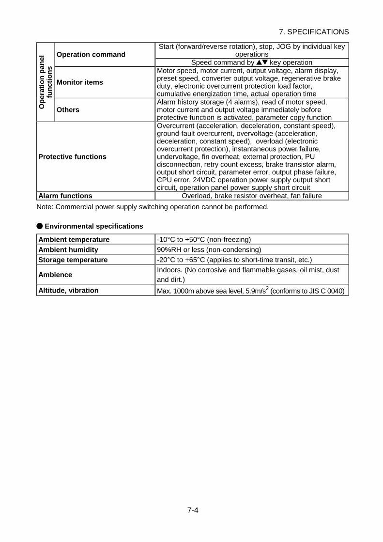
7. SPECIFICATIONS
7-4
Start (forward/reverse rotation), stop, JOG by individual keyoperationsOperation command
Speed command by key operation
Monitor items
Motor speed, motor current, output voltage, alarm display,preset speed, converter output voltage, regenerative brakeduty, electronic overcurrent protection load factor,cumulative energization time, actual operation time
Op
erat
ion
pan
elfu
nct
ion
s
OthersAlarm history storage (4 alarms), read of motor speed,motor current and output voltage immediately beforeprotective function is activated, parameter copy function
Protective functions
Overcurrent (acceleration, deceleration, constant speed),ground-fault overcurrent, overvoltage (acceleration,deceleration, constant speed), overload (electronicovercurrent protection), instantaneous power failure,undervoltage, fin overheat, external protection, PUdisconnection, retry count excess, brake transistor alarm,output short circuit, parameter error, output phase failure,CPU error, 24VDC operation power supply output shortcircuit, operation panel power supply short circuit
Alarm functions Overload, brake resistor overheat, fan failure
Note: Commercial power supply switching operation cannot be performed.
Environmental specifications
Ambient temperature -10°C to +50°C (non-freezing)
Ambient humidity 90%RH or less (non-condensing)
Storage temperature -20°C to +65°C (applies to short-time transit, etc.)
AmbienceIndoors. (No corrosive and flammable gases, oil mist, dustand dirt.)
Altitude, vibration Max. 1000m above sea level, 5.9m/s2 (conforms to JIS C 0040)
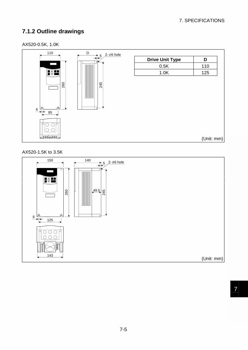
7. SPECIFICATIONS
7-5
7
7.1.2 Outline drawings
AX520-0.5K, 1.0K
Drive Unit Type D
0.5K 110
1.0K 125
110
260
D
956
5
245
2- 6 hole
(Unit: mm)
AX520-1.5K to 3.5K
150
260
140
143
1256
5
24549.5
2- 6 hole
(Unit: mm)
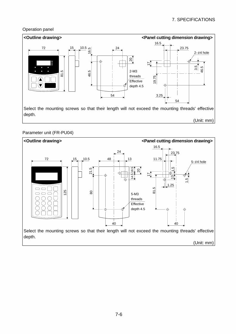
7. SPECIFICATIONS
7-6
Operation panel
<Outline drawing> <Panel cutting dimension drawing>
19.7
5
3.25
3.5
16.5
23.75
46.5
17
54
81.5
72 15 10.5
20
54
16.5
46.5
24
2-M3
threads
Effective
depth 4.5
2- 4 hole
Select the mounting screws so that their length will not exceed the mounting threads' effectivedepth.
(Unit: mm)
Parameter unit (FR-PU04)
<Outline drawing> <Panel cutting dimension drawing>
40
23.75
11.75
81.
5
1.25
1.5
131
716.5
1.5
125
72 15 10.5
18
.5
40
80
48
24
13
20
21.
5
14
.5
5-M3
threads
Effective
depth 4.5
5- 4 hole
Select the mounting screws so that their length will not exceed the mounting threads' effectivedepth.
(Unit: mm)
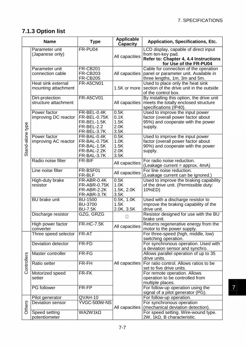
7. SPECIFICATIONS
7-7
7
7.1.3 Option list
Name Type ApplicableCapacity Application, Specifications, Etc.
Parameter unit(Japanese only)
FR-PU04
All capacities
LCD display, capable of direct inputfrom ten-key pad.Refer to: Chapter 4, 4.4 Instructions
for Use of the FR-PU04Parameter unitconnection cable
FR-CB201FR-CB203FR-CB205
All capacitiesCable for connection of the operationpanel or parameter unit. Available inthree lengths, 1m, 3m and 5m.
Heat sink externalmounting attachment
FR-A5CN011.5K or more
Used to place only the heat sinksection of the drive unit in the outsideof the control box.
Dirt-protectionstructure attachment
FR-A5CV01All capacities
By installing this option, the drive unitmeets the totally enclosed structurespecifications (IP40).
Power factorimproving DC reactor
FR-BEL-0.4KFR-BEL-0.75KFR-BEL-1.5KFR-BEL-2.2FR-BEL-3.7K
0.5K0.1K1.5K2.0K3.5K
Used to improve the input powerfactor (overall power factor about95%) and cooperate with the powersupply.
Power factorimproving AC reactor
FR-BAL-0.4KFR-BAL-0.75KFR-BAL-1.5KFR-BAL-2.2KFR-BAL-3.7K
0.5K1.0K1.5K2.0K3.5K
Used to improve the input powerfactor (overall power factor about90%) and cooperate with the powersupply.
Radio noise filter FR-BIF All capacities For radio noise reduction.(Leakage current = approx. 4mA)
Line noise filter FR-BSF01FR-BLF All capacities For line noise reduction.
(Leakage current can be ignored.)High-duty brakeresistor
FR-ABR-0.4KFR-ABR-0.75KFR-ABR-2.2KFR-ABR-3.7K
0.5K1.0K1.5K, 2.0K3.5K
Used to improve the braking capabilityof the drive unit. (Permissible duty:10%ED)
BU brake unit BU-1500BU-3700BU-7.5K
0.5K, 1.0K1.5K2.0K, 3.5K
Used with a discharge resistor toimprove the braking capability of thedrive unit.
Discharge resistor GZG, GRZG Resistor designed for use with the BUbrake unit.
Sta
nd-a
lone typ
e
High power factorconverter
FR-HC-7.5K All capacities Returns regenerative energy from themotor to the power supply.
Three speed selector FR-AT For three-speed (high, middle, low)switching operation.
Deviation detector FR-FD For synchronous operation. Used witha deviation sensor and synchro.
Master controller FR-FG Allows parallel operation of up to 35drive units.
Ratio setter FR-FH For ratio control. Allows ratios to beset to five drive units.
Motorized speedsetter
FR-FK For remote operation. Allowsoperation to be controlled frommultiple places.
Con
trolle
rs
PG follower FR-FP
All capacities
For follow-up operation using thesignal of a pilot generator (PG).
Pilot generator QVAH-10 For follow-up operation.Deviation sensor YVGC-500W-NS For synchronous operation
(mechanical deviation detection).
Oth
ers
Speed settingpotentiometer
WA2W1kΩAll capacities
For speed setting. Wire-wound type.2W, 1kΩ, B characteristic.
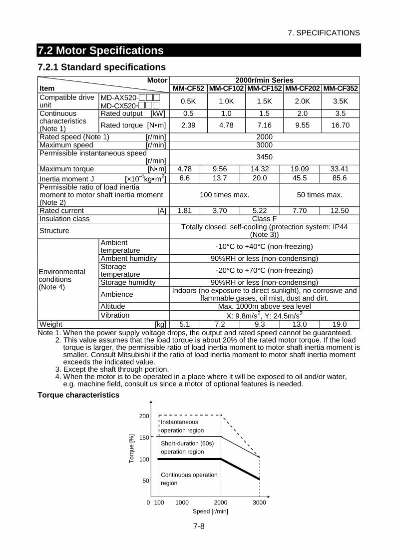
7. SPECIFICATIONS
7-8
7.2 Motor Specifications
7.2.1 Standard specificationsMotor 2000r/min Series
Item MM-CF52 MM-CF102 MM-CF152 MM-CF202 MM-CF352Compatible driveunit
MD-AX520- MD-CX520-
0.5K 1.0K 1.5K 2.0K 3.5K
Rated output [kW] 0.5 1.0 1.5 2.0 3.5Continuouscharacteristics(Note 1) Rated torque [N•m] 2.39 4.78 7.16 9.55 16.70
Rated speed (Note 1) [r/min] 2000Maximum speed [r/min] 3000Permissible instantaneous speed
[r/min] 3450
Maximum torque [N•m] 4.78 9.56 14.32 19.09 33.41Inertia moment J [×10-4kg•m2] 6.6 13.7 20.0 45.5 85.6Permissible ratio of load inertiamoment to motor shaft inertia moment(Note 2)
100 times max. 50 times max.
Rated current [A] 1.81 3.70 5.22 7.70 12.50Insulation class Class F
Structure Totally closed, self-cooling (protection system: IP44(Note 3))
Ambienttemperature -10°C to +40°C (non-freezing)
Ambient humidity 90%RH or less (non-condensing)Storagetemperature -20°C to +70°C (non-freezing)
Storage humidity 90%RH or less (non-condensing)
Ambience Indoors (no exposure to direct sunlight), no corrosive andflammable gases, oil mist, dust and dirt.
Altitude Max. 1000m above sea level
Environmentalconditions(Note 4)
Vibration X: 9.8m/s2, Y: 24.5m/s2
Weight [kg] 5.1 7.2 9.3 13.0 19.0Note 1. When the power supply voltage drops, the output and rated speed cannot be guaranteed.
2. This value assumes that the load torque is about 20% of the rated motor torque. If the loadtorque is larger, the permissible ratio of load inertia moment to motor shaft inertia moment issmaller. Consult Mitsubishi if the ratio of load inertia moment to motor shaft inertia momentexceeds the indicated value.
3. Except the shaft through portion.4. When the motor is to be operated in a place where it will be exposed to oil and/or water,
e.g. machine field, consult us since a motor of optional features is needed.
Torque characteristics
200
150
100
50
0 100 1000 2000 3000
Speed [r/min]
To
rqu
e [%
]
Instantaneous
operation region
Short-duration (60s)
operation region
Continuous operationregion
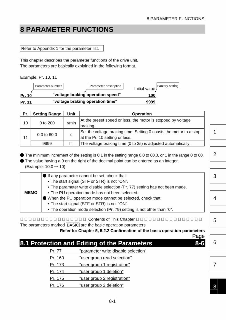
8 PARAMETER FUNCTIONS
8-1
1
2
3
4
5
6
7
8
8 PARAMETER FUNCTIONS
Refer to Appendix 1 for the parameter list.
This chapter describes the parameter functions of the drive unit.The parameters are basically explained in the following format.
Example: Pr. 10, 11
Pr. 10 100
Pr. 11 9999"voltage braking operation time"
Parameter number Parameter description Factory settingInitial value
"voltage braking operation speed"
Pr. Setting Range Unit Operation
10 0 to 200 r/minAt the preset speed or less, the motor is stopped by voltagebraking.
0.0 to 60.0 sSet the voltage braking time. Setting 0 coasts the motor to a stopat the Pr. 10 setting or less.11
9999 The voltage braking time (0 to 3s) is adjusted automatically.
The minimum increment of the setting is 0.1 in the setting range 0.0 to 60.0, or 1 in the range 0 to 60.
The value having a 0 on the right of the decimal point can be entered as an integer.(Example: 10.0 10)
MEMO
If any parameter cannot be set, check that:• The start signal (STF or STR) is not "ON".• The parameter write disable selection (Pr. 77) setting has not been made.• The PU operation mode has not been selected. When the PU operation mode cannot be selected, check that:• The start signal (STF or STR) is not "ON".• The operation mode selection (Pr. 79) setting is not other than "0".
Contents of This Chapter The parameters marked BASIC are the basic operation parameters.
Refer to: Chapter 5, 5.2.2 Confirmation of the basic operation parametersPage
8.1 Protection and Editing of the Parameters 8-6Pr. 77 "parameter write disable selection"
Pr. 160 "user group read selection"
Pr. 173 "user group 1 registration"
Pr. 174 "user group 1 deletion"
Pr. 175 "user group 2 registration"
Pr. 176 "user group 2 deletion"
8 PARAMETER FUNCTIONS
8-2
Pr. 199 "user's initial value setting"
8.2 Selection of the Operation Mode 8-8BASIC Pr. 79 "operation mode selection"
BASIC Pr. 75 "disconnected PU detection/PU stop selection"
8.3 Selection of the Speed Command 8-128.3.1 Selection of the analog speed command specifications ................... 8-12
BASIC Pr. 73 "speed command range selection"
Pr. 74 "filter time constant"
Pr. 252 "override bias"
Pr. 253 "override gain"
BASIC Pr. 902 "speed setting voltage bias"
BASIC Pr. 903 "speed setting voltage gain"
BASIC Pr. 904 "speed setting current bias"
BASIC Pr. 905 "speed setting current gain"
8.3.2 Variable-speed operation using contact input signals ...................... 8-18BASIC Pr. 4 "three-speed setting (high speed)"
BASIC Pr. 5 "three-speed setting (middle speed)"
BASIC Pr. 6 "three-speed setting (low speed)"
Pr. 24 to 27 "multi-speed setting (speed 4 to 7)"
Pr. 232 to 239 "multi-speed setting (speed 8 to 15)"
Pr. 59 "remote setting function selection"
Pr. 28 "contact input speed compensation"
8.4 Selection of the Control Circuit Contact Input Terminal Functions8-21
Pr. 17 "MRS input selection"
Pr. 180 "RL terminal function selection"
Pr. 181 "RM terminal function selection"
Pr. 182 "RH terminal function selection"
Pr. 183 "RT terminal function selection"
Pr. 184 "AU terminal function selection"
Pr. 185 "JOG terminal function selection"
Pr. 186 "CS terminal function selection"
Pr. 187 "MRS terminal function selection"
Pr. 188 "RES terminal operation selection"
Pr. 189 "STF, STR terminal operation selection"
8 PARAMETER FUNCTIONS
8-3
8
8.5 Setting of the Operation Pattern 8-248.5.1 Running speed region...................................................................... 8-24
BASIC Pr. 1 "maximum speed"
BASIC Pr. 2 "minimum speed"
Pr. 13 "minimum motor speed"
Pr. 31 to 36 "speed command jumps 1A to 3B"
BASIC Pr. 78 "reverse rotation prevention selection"
8.5.2 Acceleration time and deceleration time .......................................... 8-26BASIC Pr. 7 "acceleration time"
BASIC Pr. 8 "deceleration time"
Pr. 20 "acceleration/deceleration reference speed"
Pr. 21 "acceleration/deceleration time unit"
Pr. 44 "second acceleration time"
Pr. 45 "second deceleration time"
Pr. 110 "third acceleration time"
Pr. 111 "third deceleration time"
8.5.3 Acceleration/deceleration patterns................................................... 8-28Pr. 29 "acceleration/deceleration pattern"
8.5.4 Stopping operation........................................................................... 8-29Pr. 10 "braking voltage operation speed"
Pr. 11 "braking voltage operation time"
Pr. 250 "coasting-to-stop setting"
8.5.5 Selection of regenerative brake unit................................................. 8-30Pr. 30 "regenerative brake option selection"
Pr. 70 "regenerative brake duty"
8.5.6 Stall prevention operation level ........................................................ 8-31Pr. 22 "stall prevention operation level"
Pr. 156 "stall prevention operation selection"
8.5.7 Selection of motor tone.................................................................... 8-32Pr. 72 "motor tone selection"
8.5.8 Other settings .................................................................................. 8-32Pr. 9 "electronic thermal O/L relay"
Pr. 84 "rated motor speed"
Pr. 244 "cooling fan operation selection"
Pr. 990 "buzzer control"

8 PARAMETER FUNCTIONS
8-4
8.6 Setting of Various Operation Methods 8-348.6.1 JOG operation ................................................................................. 8-34
Pr. 15 "JOG speed"
Pr. 16 "JOG acceleration/deceleration time"
8.6.2 Communication operation from the PU connector............................ 8-35Pr. 117 "station number"
Pr. 118 "communication speed"
Pr. 119 "stop bit length/data length"
Pr. 120 "parity check presence/absence"
Pr. 121 "number of communication retries"
Pr. 122 "communication check time interval"
Pr. 123 "waiting time setting"
Pr. 124 "CR-LF presence/absence selection"
8.6.3 PID control operation ....................................................................... 8-45Pr. 128 "PID action selection"
Pr. 129 "PID proportional band"
Pr. 130 "PID integral time"
Pr. 131 "upper limit"
Pr. 132 "lower limit"
Pr. 133 "PID action set point for PU operation"
Pr. 134 "PID differential time"
8.6.4 Alarm retry operation ....................................................................... 8-52Pr. 65 "retry item selection"
Pr. 67 "retry count selection"
Pr. 68 "retry time selection"
Pr. 69 "retry count display"
8.6.5 Power failure deceleration-to-stop operation.................................... 8-54Pr. 261 "power failure stop selection"
Pr. 262 "subtracted speed at deceleration start"
Pr. 263 "subtraction starting speed"
Pr. 264 "power-failure deceleration time 1"
Pr. 265 "power-failure deceleration time 2"
Pr. 266 "power-failure deceleration time switch-over speed"

8 PARAMETER FUNCTIONS
8-5
8
8.7 Monitoring of Operation Status 8-558.7.1 Selection of operation panel display data......................................... 8-55
Pr. 37 "speed unit switch-over 1"
Pr. 144 "speed unit switch-over 2"
Pr. 52 "main display screen data selection"
Pr. 171 "actual operation hour meter clear"
Pr. 53 "level display data selection"
8.7.2 Selection of the control circuit output terminal functions................... 8-58Pr. 190 "RUN terminal function selection"
Pr. 191 "SU terminal function selection"
Pr. 192 "IPF terminal function selection"
Pr. 193 "OL terminal function selection"
Pr. 194 "FU terminal function selection"
Pr. 195 "A, B, C terminal function selection"
Pr. 157 "OL signal output timer"
Pr. 76 "alarm code output selection"
8.7.3 Detection of running speed .............................................................. 8-61Pr. 41 "up-to-speed sensitivity"
Pr. 42 "speed detection"
Pr. 43 "speed detection for reverse rotation"
Pr. 50 "second speed detection"
Pr. 116 "third speed detection"
8.7.4 Detection of output current............................................................... 8-63Pr. 150 "output current detection level"
Pr. 151 "output current detection time"
8.7.5 Selection of the instrument connection terminal functions................ 8-64Pr. 54 "FM terminal function selection"
Pr. 158 "AM terminal function selection"
Pr. 55 "speed monitoring reference"
Pr. 56 "current monitoring reference"
Pr. 900 "FM terminal calibration"
Pr. 901 "AM terminal calibration"
8.8 Control Parameters 8-67
APPENDIX 1 PARAMETER LIST (NUMERICAL ORDER) 8-69

8 PARAMETER FUNCTIONS
8-6
8.1 Protection and Editing of the Parameters
Initial value
Pr. 77 "parameter write disable selection" 0
You can select between write-enable and disable for parameter setting.
Setting Function Exceptional Parameters
0
You can change the setting onlyduring a stop in the PU operationmode.
Even during operation, you can change the values
of the parameters whose numbers are shaded
in the parameter list in Appendix 1. However, Pr. 72
allows its setting to be changed in the PU operation
mode only.
1
Whether the motor is running or ata stop, you cannot change thesettings in any operation mode.Parameter clear, parameter allclear and user clear operations arealso disabled.
Pr. 22 [Section 8.5.6], Pr. 75 [Section 8.2], Pr. 77,Pr. 79 [Section 8.2], and Pr. 188 [Section 8.4] allowtheir values to be changed in any operation mode.
2Whether the motor is running or ata stop, you can change the valuesin any operation mode.
Pr. 79 [Section 8.2], Pr. 180 to 187, Pr. 189[Section 8.4], and Pr. 190 to 195 [Section 8.7.2]allow their values to be changed during a stop only.
Initial value
Pr. 160 "user group read selection" 0
Pr. 173 "user group 1 registration" 0
Pr. 174 "user group 1 deletion" 0
Pr. 175 "user group 2 registration" 0
Pr. 176 "user group 2 deletion" 0
From among all parameters, a total of 32 parameters can be registered to two different user groups.The registered parameters may only be accessed for reading and writing.
By setting the required value in Pr. 160, make the user groups valid or invalid.
Setting Description
0User groups are made invalid and all parameters can be accessed for read and
write.
1 Only the parameters registered to user group 1 can be accessed for read and write.
10 Only the parameters registered to user group 2 can be accessed for read and write.
11Only the parameters registered to user groups 1 and 2 can be accessed for readand write.
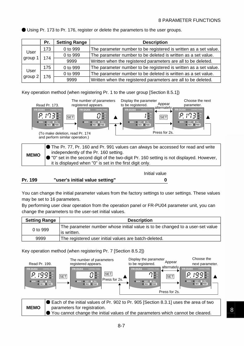
8 PARAMETER FUNCTIONS
8-7
8
Using Pr. 173 to Pr. 176, register or delete the parameters to the user groups.
Pr. Setting Range Description
173 0 to 999 The parameter number to be registered is written as a set value.0 to 999 The parameter number to be deleted is written as a set value.
Usergroup 1 174
9999 Written when the registered parameters are all to be deleted.175 0 to 999 The parameter number to be registered is written as a set value.
0 to 999 The parameter number to be deleted is written as a set value.User
group 2 1769999 Written when the registered parameters are all to be deleted.
Key operation method (when registering Pr. 1 to the user group [Section 8.5.1])
SET
FR-DU04 CONTROL PANEL
Hz
MON EXT PU
AV
REV FWD
SET
FR-DU04 CONTROL PANEL
Hz
MON EXT PU
AV
REV FWD
FR-DU04 CONTROL PANEL
Hz
MON EXT PU
AV
REV FWD
FR-DU04 CONTROL PANEL
Hz
MON EXT PU
AV
REV FWD
Press for 2s.
Read Pr. 173. parameter.
and perform similar operation.)
alternately.Appearregistered appears.
The number of parametersto be registered.Display the parameter Choose the next
(To make deletion, read Pr. 174
MEMO
The Pr. 77, Pr. 160 and Pr. 991 values can always be accessed for read and writeindependently of the Pr. 160 setting. "0" set in the second digit of the two-digit Pr. 160 setting is not displayed. However,it is displayed when "0" is set in the first digit only.
Initial value
Pr. 199 "user's initial value setting" 0
You can change the initial parameter values from the factory settings to user settings. These valuesmay be set to 16 parameters.By performing user clear operation from the operation panel or FR-PU04 parameter unit, you canchange the parameters to the user-set initial values.
Setting Range Description
0 to 999The parameter number whose initial value is to be changed to a user-set valueis written.
9999 The registered user initial values are batch-deleted.
Key operation method (when registering Pr. 7 [Section 8.5.2])
FR-DU04 CONTROL PANEL
Hz
MON EXT PU
AV
REV FWD
SET
FR-DU04 CONTROL PANEL
Hz
MON EXT PU
AV
REV FWD
SET
FR-DU04 CONTROL PANEL
Hz
MON EXT PU
AV
REV FWD
FR-DU04 CONTROL PANEL
Hz
MON EXT PU
AV
REV FWD
SET
Press for 2s.
Read Pr. 199.
Press for 2s.
Display the parameterAppear
alternately.
Choose the
next parameter.The number of parametersregistered appears. to be registered.
MEMO Each of the initial values of Pr. 902 to Pr. 905 [Section 8.3.1] uses the area of twoparameters for registration. You cannot change the initial values of the parameters which cannot be cleared.

8 PARAMETER FUNCTIONS
8-8
8.2 Selection of the Operation Mode
Initial value
Pr. 79 "operation mode selection" 0
The setting range is 0 to 4 and 6 to 8.
When the operation mode is fixed (Setting 0 to 4)
Setting Mode Function (Refer to: Chapter 5, 5.3 Operation Examples)
0PU/external operationswitching
You can perform operation by changing between the PUoperation mode and external operation mode from the operationpanel or parameter unit (FR-PU04).The unit is placed in the external operation mode at power-on.
1 PU operation The PU operation mode is made valid.2 External operation The external operation mode is made valid.
3External/PUcombined operation 1
The external/PU combined operation mode 1 is made valid.
4External/PUcombined operation 2
The external/PU combined operation mode 2 is made valid.
Operation Mode Input of Start Signal Input of Speed Setting Signal
PU operation mode(when usingoperation panel)
From operation panel
STOP/RESET
FWD REV
From operation panel
External operationmode
From control circuit terminals
STF
STR
SD
From control circuit terminals
10E
2
5
RM
RL
SD
RH
4
5
External/PUcombined operation 1(when usingoperation panel)
From control circuit terminals
STF
STR
SD
From operation panel
Multi-speed input is also enabled from
control circuit terminals.
External/PUcombined operation 2(when usingoperation panel)
From operation panel
STOP/RESET
FWD REV
From control circuit terminals
10E
2
5
RM
RL
SD
RH
4
5

8 PARAMETER FUNCTIONS
8-9
8
When the operation mode switching condition is specified (Setting 6 to 8)Setting Mode Function
6 Switch-over
In response to the selection of the PU operation mode orexternal operation mode from the operation panel or parameterunit (FR-PU04), the operation command right can be changedfrom the external operation to the PU operation or from the PUoperation to the external operation without stopping theoperation.
The operation in the switch-over mode is performed as described in the following table.
Operation Mode Switching Switching Control/Operation Status
External operation PU operation
The operation mode is switched to the PU operation mode.• The rotation direction remains unchanged from the direction
of the external operation.• The speed remains unchanged from the setting of the
external operation. (Once power is switched "OFF" or areset is made, the stored setting of the external operation iscleared to "0" and the operation stops.)
PU operation external operation
The operation mode is switched to the external operation mode.• The rotation direction is determined by the input signal of the
external operation.• The speed is determined by the external setting signal.
Setting Mode Function
7 PU operationinterlock
When the contact input terminal for the X12 signal has beenselected is "OFF", the operation mode is fixed to the externaloperation mode.To switch it to the PU operation mode, turn "ON" the X12 signaland change the operation mode from the operation panel.Turning the X12 signal "OFF" automatically returns the operationmode to the external operation mode.When the X12 signal is not selected, the MRS terminal acts asthe terminal having the function of the X12 signal.
Refer to: 8.4 Selection of the Control Circuit ContactInput Terminal Functions
1) Change of operation status when X12 signal is turned from "OFF" to "ON"
Operation Status When X12 Signal = "OFF" Operation Status After X12 Signal = "ON"PU operation
mode Operation disabled PU operationmode
Operation enabled by controlexercised in PU operation mode.
During stop During stopExternaloperation
mode During operation
Externaloperation
mode Output stop
2) Change of operation status when X12 signal is turned from "ON" to "OFF"
Operation Status When X12 Signal = "ON" Operation Status After X12 Signal = "OFF"During stop During stop
PU operationmode During operation
Operation is performed inaccordance with the speed settingand start signal of the externaloperation if they are input.
Externaloperation
modeOperation disabled
Externaloperation
mode Operation is performed inaccordance with the speed settingand start signal of the externaloperation if they are input.

8 PARAMETER FUNCTIONS
8-10
Setting Mode Function
8 External signalswitching
When the contact input terminal where the X16 signal has beenselected is "ON", the operation mode is fixed to the externaloperation mode, or when that terminal is "OFF", the operationmode is fixed to the PU operation mode.Switching is enabled during a stop only.
Refer to: 8.4 Selection of the Control Circuit ContactInput Terminal Functions
MEMO
If the X12 signal is "ON" in the PU operation interlock mode, the operation modecannot be changed to PU operation when the start signal (STF, STR) is "ON".Switching to external operation is independent of "ON"/"OFF" of the start signal.When the X12 signal is turned "OFF" with the start signal "ON", operation isperformed in accordance with the external operation command. When the MRS terminal is used as the X12 signal, the signal logic change set inPr. 17 [Section 8.4] is valid. When using the unit in the communication operation mode from the PU connector,change the operation mode through communication. You need not set Pr. 79.
Refer to: 8.6.2 Communication operation from PU connector

8 PARAMETER FUNCTIONS
8-11
8
Initial value
Pr. 75 "disconnected PU detection/PU stop selection" 0
Disconnected PU detection functionYou can make selection between continued operation or an alarm stop ("E. PUE" indication)when the operation panel or FR-PU04 parameter unit has come off the drive unit duringoperation.
MEMO This function is invalid if power is switched on with the operation panel or FR-PU04parameter unit removed.
PU stop selectionSelect the operation mode in which an operation stop is made valid by the STOP/RESET key ofthe operation panel or FR-PU04 parameter unit.
SettingPU DisconnectionDetection Function
PU Stop Selection Operation Mode
0 Operation continued.
1 Alarm stop.
Any operation mode.When operation is stopped in the external operation mode orPU/external combined operation mode 1, "PS" appears in themain indicator LED. No alarm signal is output.
2 Operation continued.3 Alarm stop.
PU operation mode, PU/external combined operation mode 2.
Restarting method when "PS" appears in the main indicator LED
To restart operation, turn "OFF" the operation command (STF or STR) signal, perform the followingoperation, and then turn "ON" the operation command.
(1) When using the operation panel1) Press the MODE key of the operation panel three times to display the external operation
mode screen ("OP.nd" indication).When Pr. 79 = 3, press the MODE key three times, then press the key.
2) Press the SET key.
(2) When using the FR-PU04 parameter unit1) Press the EXT key.
MEMO
In the communication operation mode, the PU disconnection detection function isinvalid. Pr. 75 does not return to the initial value if parameter clear or all clear [Section 4.3]is performed.

8 PARAMETER FUNCTIONS
8-12
8.3 Selection of the Speed Command
8.3.1 Selection of the analog speed command specifications
Initial value
Pr. 73 "speed command range selection" 0
You can select the specifications of the speed command input terminals, forward/reverse rotationoperation according to the input signal polarity, and the override function.When using the terminal 2 only, set "0" or "1" ("10" or "11" for polarity reversible operation) in thisparameter. This function can be used with other speed command terminals.
(1) When terminal 2 is used for main speed, terminal 1 for auxiliary speed, and thesesignals are added for use as speed command
Setting Terminal 2 InputVoltage
Terminal 1 InputVoltage
Polarity ReversibleOperation AU Signal
0 0 to 10V1 0 to 5V 0 to ±10V
2 0 to 10V3 0 to 5V 0 to ±5V
Operation isstopped when theresult of addition is anegative value.
10 0 to 10V11 0 to 5V 0 to ±10V
12 0 to 10V13 0 to 5V 0 to ±5V
Reverse operation isperformed when theresult of addition is anegative value.
Turn "OFF" thecontact inputterminal where theAU signal has beenselected [Section8.4].
(2) When terminal 4 is used for main speed, terminal 1 for auxiliary speed, and thesesignals are added for use as speed command
Setting Terminal 4 InputVoltage
Terminal 1 InputVoltage
Polarity ReversibleOperation AU Signal
01 0 to ±10V
23 0 to ±5V
Operation isstopped when theresult of addition is anegative value.
1011 0 to ±10V
1213
4 to 20mA
0 to ±5V
Reverse operation isperformed when theresult of addition is anegative value.
Turn "ON" thecontact inputterminal where theAU signal has beenselected [Section8.4].
(3) When the main speed of terminal 1 is compensated for by the values set in Pr. 252and Pr. 253 from terminal 2 and the result is used as speed command
Setting Terminal 1 InputVoltage
Terminal 2 InputVoltage
Polarity ReversibleOperation AU Signal
4 0 to ±10V 0 to 10V
5 0 to ±5V 0 to 5V
Operation isstopped when themain speed signal isa negative value.
14 0 to ±10V 0 to 10V
15 0 to ±5V 0 to 5V
Reverse operation isperformed when themain speed signal isa negative value.
Turn "OFF" thecontact inputterminal where theAU signal has beenselected [Section8.4].
(4) When the main speed of terminal 4 is compensated for by the values set in Pr. 252and Pr. 253 from terminal 2 and the result is used as speed command
Setting Terminal 4 InputVoltage
Terminal 2 InputVoltage AU Signal
4 0 to 10V
54 to 20mA
0 to 5V
Turn "ON" the contact input terminalwhere the AU signal has been selected[Section 8.4].

8 PARAMETER FUNCTIONS
8-13
8
Initial value
Pr. 74 "filter time constant" 1
You can set the filter time constants of the speed command input terminals (terminals 2, 1, 4).Increase the value if stable operation cannot be performed due to the influence of noise on thespeed command signal. Decreasing the value makes the speed command signal more susceptibleto noise but the response of the speed command faster. Conversely, increasing the value makesthe speed command signal less susceptible to noise but the response of the speed commandslower.
Setting
0 to 8
Initial value
Pr. 252 "override bias" 50
Pr. 253 "override gain" 150
Speed compensation of a given ratio is made for the main speed setting signal.The relationship between the compensation speed and override value is as indicated below.
αCompensation speed = pre-compensation speed ×
100(r/min)
α: Override value (%)
Use Pr. 74 when the Pr. 73 setting is any of 4, 5, 14 and 15.
Parameter Number Setting Range Unit
252 0.0 to 200.0 %253 0.0 to 200.0 %
0V 5V(2.5V)
10V(5V)
0
50
100
150
200
Pr. 253
Voltage across terminals 2-5
Pr. 252
Ove
rrid
e va
lue
(%
)
Factory setting
(50% to 150%)

8 PARAMETER FUNCTIONS
8-14
Initial value
Pr. 902 "speed setting voltage bias" Approx. 0/0
Pr. 903 "speed setting voltage gain" Approx. 100/2000
You can set the relationship between the magnitude of the speed setting analog voltage signal inputto the terminal 2 and the motor speed. 0V of the speed setting signal corresponds to approx. 0%,and 5V or 10V (depending on Pr. 73 setting) to approx. 100%.
Setting RangePr.
Motor speed UnitSpeed setting
signalUnit
902 0 to 2000 0.0 to 300.0903 1 to 3000
r/min0.0 to 300.0
%
2000
0 100Speed setting signal (%)
Run
nin
g
spe
ed (
r/m
in)
Factory setting
Gain
Pr. 903Bias
Pr. 902
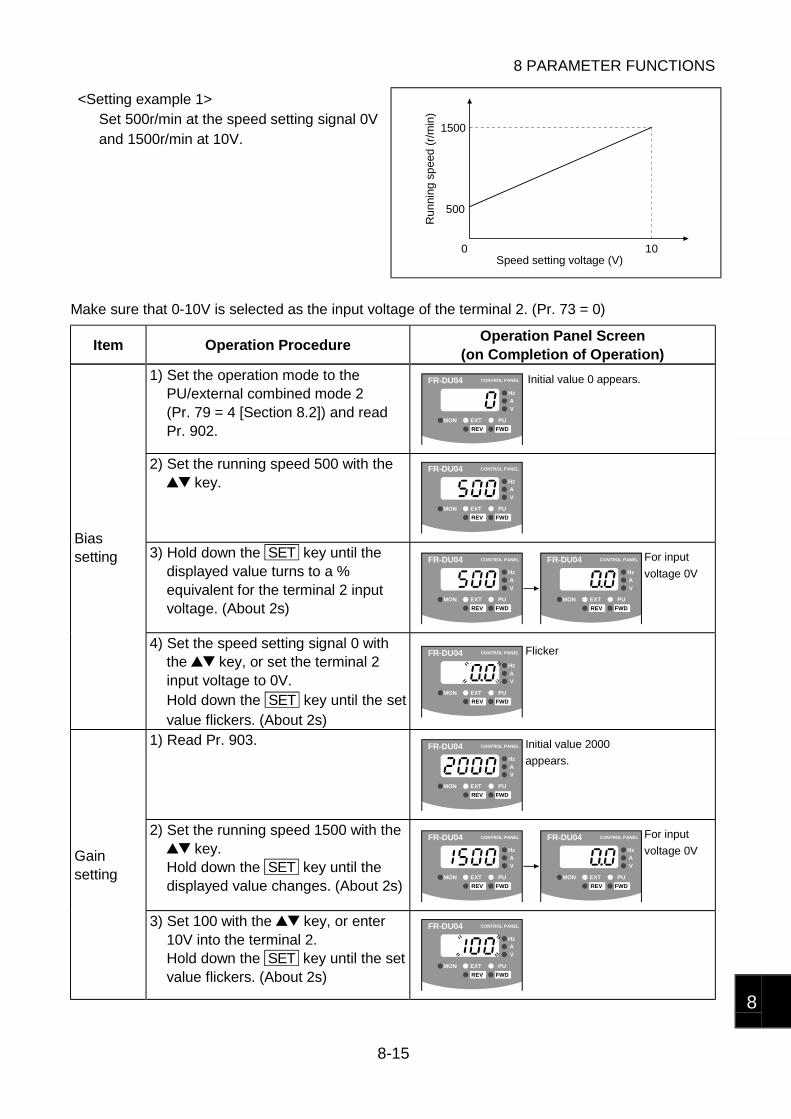
8 PARAMETER FUNCTIONS
8-15
8
<Setting example 1>Set 500r/min at the speed setting signal 0Vand 1500r/min at 10V.
1500
500
0 10
Ru
nnin
g s
pee
d (r
/min
)
Speed setting voltage (V)
Make sure that 0-10V is selected as the input voltage of the terminal 2. (Pr. 73 = 0)
Item Operation ProcedureOperation Panel Screen
(on Completion of Operation)
1) Set the operation mode to thePU/external combined mode 2(Pr. 79 = 4 [Section 8.2]) and readPr. 902.
FR-DU04 CONTROL PANEL
Hz
MON EXT PU
AV
REV FWD
Initial value 0 appears.
2) Set the running speed 500 with the key.
FR-DU04 CONTROL PANEL
Hz
MON EXT PU
AV
REV FWD
3) Hold down the SET key until thedisplayed value turns to a %equivalent for the terminal 2 inputvoltage. (About 2s)
FR-DU04 CONTROL PANEL
Hz
MON EXT PU
AV
REV FWD
FR-DU04 CONTROL PANEL
Hz
MON EXT PU
AV
REV FWD
For input
voltage 0V
Biassetting
4) Set the speed setting signal 0 withthe key, or set the terminal 2input voltage to 0V.Hold down the SET key until the setvalue flickers. (About 2s)
FR-DU04 CONTROL PANEL
Hz
MON EXT PU
AV
REV FWD
Flicker
1) Read Pr. 903. FR-DU04 CONTROL PANEL
Hz
MON EXT PU
AV
REV FWD
Initial value 2000
appears.
2) Set the running speed 1500 with the key.
Hold down the SET key until thedisplayed value changes. (About 2s)
FR-DU04 CONTROL PANEL
Hz
MON EXT PU
AV
REV FWD
FR-DU04 CONTROL PANEL
Hz
MON EXT PU
AV
REV FWD
For input
voltage 0VGainsetting
3) Set 100 with the key, or enter10V into the terminal 2.Hold down the SET key until the setvalue flickers. (About 2s)
FR-DU04 CONTROL PANEL
Hz
MON EXT PU
AV
REV FWD
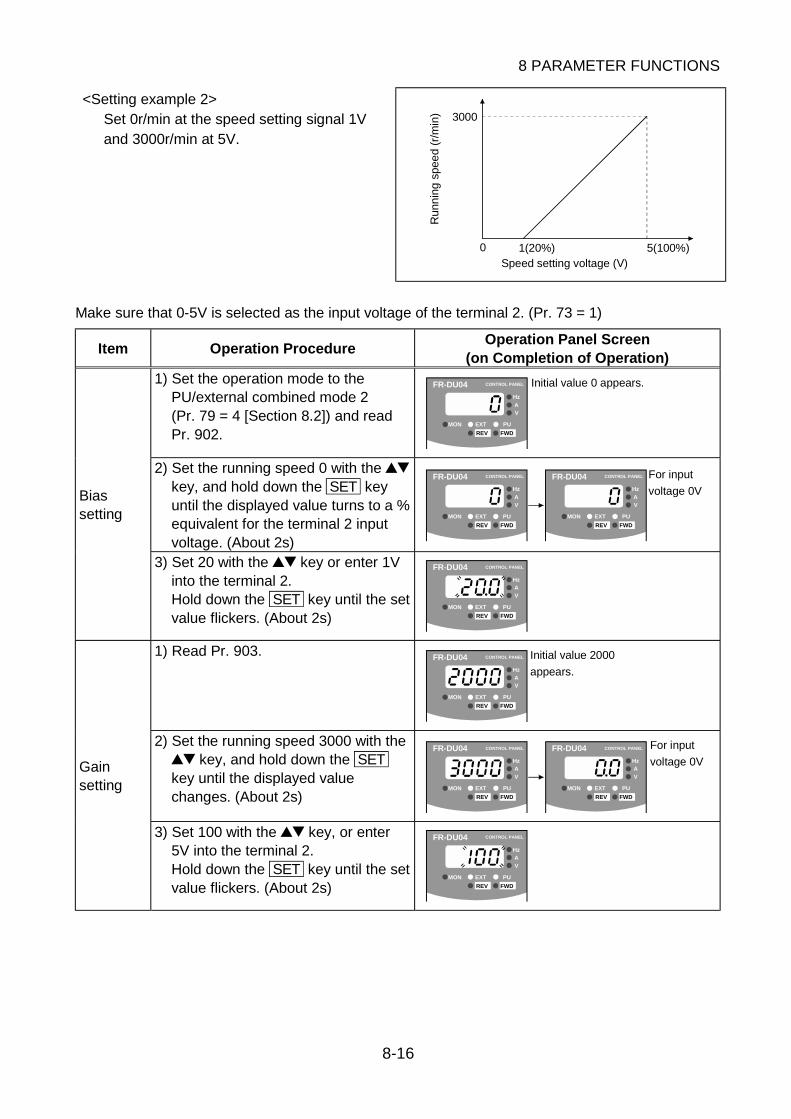
8 PARAMETER FUNCTIONS
8-16
<Setting example 2>Set 0r/min at the speed setting signal 1Vand 3000r/min at 5V.
3000
0 1(20%) 5(100%)Speed setting voltage (V)
Run
nin
g s
pee
d (r
/min
)
Make sure that 0-5V is selected as the input voltage of the terminal 2. (Pr. 73 = 1)
Item Operation ProcedureOperation Panel Screen
(on Completion of Operation)
1) Set the operation mode to thePU/external combined mode 2(Pr. 79 = 4 [Section 8.2]) and readPr. 902.
FR-DU04 CONTROL PANEL
Hz
MON EXT PU
AV
REV FWD
Initial value 0 appears.
2) Set the running speed 0 with the key, and hold down the SET keyuntil the displayed value turns to a %equivalent for the terminal 2 inputvoltage. (About 2s)
FR-DU04 CONTROL PANEL
Hz
MON EXT PU
AV
REV FWD
FR-DU04 CONTROL PANEL
Hz
MON EXT PU
AV
REV FWD
For input
voltage 0VBiassetting
3) Set 20 with the key or enter 1Vinto the terminal 2.Hold down the SET key until the setvalue flickers. (About 2s)
FR-DU04 CONTROL PANEL
Hz
MON EXT PU
AV
REV FWD
1) Read Pr. 903. FR-DU04 CONTROL PANEL
Hz
MON EXT PU
AV
REV FWD
Initial value 2000
appears.
2) Set the running speed 3000 with the key, and hold down the SET
key until the displayed valuechanges. (About 2s)
FR-DU04 CONTROL PANEL
Hz
MON EXT PU
AV
REV FWD
FR-DU04 CONTROL PANEL
Hz
MON EXT PU
AV
REV FWD
For input
voltage 0VGainsetting
3) Set 100 with the key, or enter5V into the terminal 2.Hold down the SET key until the setvalue flickers. (About 2s)
FR-DU04 CONTROL PANEL
Hz
MON EXT PU
AV
REV FWD

8 PARAMETER FUNCTIONS
8-17
8
Initial value
Pr. 904 "speed setting current bias" Approx. 20/0
Pr. 905 "speed setting current gain" Approx. 100/2000
You can set the relationship between the magnitude of the speed setting analog current signal inputto the terminal 4 and the motor speed. 0mA of the speed setting signal corresponds to approx. 0%,and 20mA to approx. 100%.
Setting RangePr.
Motor speed UnitSpeed setting
signalUnit
904 0 to 2000 0.0 to 300.0905 1 to 3000
r/min0.0 to 300.0
%
You can set these parameter values as when you set the speed setting voltage bias and gain inPr. 902 and Pr. 903.
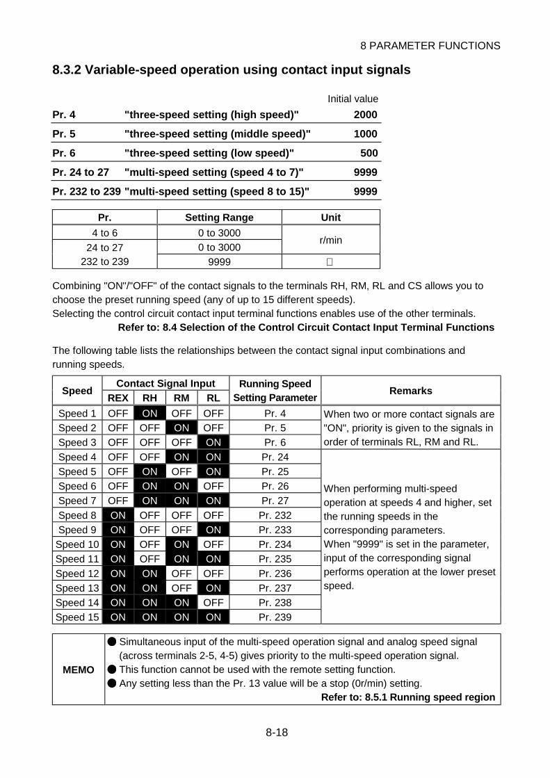
8 PARAMETER FUNCTIONS
8-18
8.3.2 Variable-speed operation using contact input signals
Initial value
Pr. 4 "three-speed setting (high speed)" 2000
Pr. 5 "three-speed setting (middle speed)" 1000
Pr. 6 "three-speed setting (low speed)" 500
Pr. 24 to 27 "multi-speed setting (speed 4 to 7)" 9999
Pr. 232 to 239 "multi-speed setting (speed 8 to 15)" 9999
Pr. Setting Range Unit
4 to 6 0 to 3000
0 to 3000r/min
24 to 27232 to 239 9999
Combining "ON"/"OFF" of the contact signals to the terminals RH, RM, RL and CS allows you tochoose the preset running speed (any of up to 15 different speeds).Selecting the control circuit contact input terminal functions enables use of the other terminals.
Refer to: 8.4 Selection of the Control Circuit Contact Input Terminal Functions
The following table lists the relationships between the contact signal input combinations andrunning speeds.
Contact Signal InputSpeed
REX RH RM RLRunning Speed
Setting ParameterRemarks
Speed 1 OFF ON OFF OFF Pr. 4
Speed 2 OFF OFF ON OFF Pr. 5
Speed 3 OFF OFF OFF ON Pr. 6
When two or more contact signals are"ON", priority is given to the signals inorder of terminals RL, RM and RL.
Speed 4 OFF OFF ON ON Pr. 24
Speed 5 OFF ON OFF ON Pr. 25
Speed 6 OFF ON ON OFF Pr. 26
Speed 7 OFF ON ON ON Pr. 27
Speed 8 ON OFF OFF OFF Pr. 232
Speed 9 ON OFF OFF ON Pr. 233
Speed 10 ON OFF ON OFF Pr. 234
Speed 11 ON OFF ON ON Pr. 235
Speed 12 ON ON OFF OFF Pr. 236
Speed 13 ON ON OFF ON Pr. 237
Speed 14 ON ON ON OFF Pr. 238
Speed 15 ON ON ON ON Pr. 239
When performing multi-speedoperation at speeds 4 and higher, setthe running speeds in thecorresponding parameters.When "9999" is set in the parameter,input of the corresponding signalperforms operation at the lower presetspeed.
MEMO
Simultaneous input of the multi-speed operation signal and analog speed signal(across terminals 2-5, 4-5) gives priority to the multi-speed operation signal.
This function cannot be used with the remote setting function.
Any setting less than the Pr. 13 value will be a stop (0r/min) setting.Refer to: 8.5.1 Running speed region
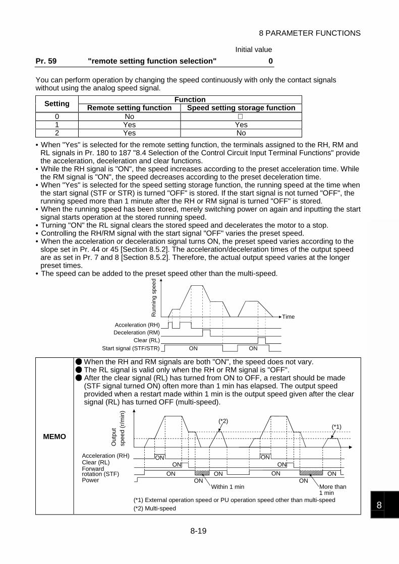
8 PARAMETER FUNCTIONS
8-19
8
Initial value
Pr. 59 "remote setting function selection" 0
You can perform operation by changing the speed continuously with only the contact signalswithout using the analog speed signal.
FunctionSetting Remote setting function Speed setting storage function0 No 1 Yes Yes2 Yes No
• When "Yes" is selected for the remote setting function, the terminals assigned to the RH, RM andRL signals in Pr. 180 to 187 "8.4 Selection of the Control Circuit Input Terminal Functions" providethe acceleration, deceleration and clear functions.
• While the RH signal is "ON", the speed increases according to the preset acceleration time. Whilethe RM signal is "ON", the speed decreases according to the preset deceleration time.
• When "Yes" is selected for the speed setting storage function, the running speed at the time whenthe start signal (STF or STR) is turned "OFF" is stored. If the start signal is not turned "OFF", therunning speed more than 1 minute after the RH or RM signal is turned "OFF" is stored.
• When the running speed has been stored, merely switching power on again and inputting the startsignal starts operation at the stored running speed.
• Turning "ON" the RL signal clears the stored speed and decelerates the motor to a stop.• Controlling the RH/RM signal with the start signal "OFF" varies the preset speed.• When the acceleration or deceleration signal turns ON, the preset speed varies according to the
slope set in Pr. 44 or 45 [Section 8.5.2]. The acceleration/deceleration times of the output speedare as set in Pr. 7 and 8 [Section 8.5.2]. Therefore, the actual output speed varies at the longerpreset times.
• The speed can be added to the preset speed other than the multi-speed.
TimeRu
nnin
g s
pee
d
Acceleration (RH)Deceleration (RM)
Clear (RL)
Start signal (STF/STR) ONON
MEMO
When the RH and RM signals are both "ON", the speed does not vary. The RL signal is valid only when the RH or RM signal is "OFF". After the clear signal (RL) has turned from ON to OFF, a restart should be made(STF signal turned ON) often more than 1 min has elapsed. The output speedprovided when a restart made within 1 min is the output speed given after the clearsignal (RL) has turned OFF (multi-speed).
(*1)
ON
ONON
ON
ON
ON
ONON
ON
ON
(*2)
(*1) External operation speed or PU operation speed other than multi-speed
(*2) Multi-speed
Out
pu
t
spee
d (
r/m
in)
Acceleration (RH)Clear (RL)Forward
PowerWithin 1 min More than
rotation (STF)
1 min
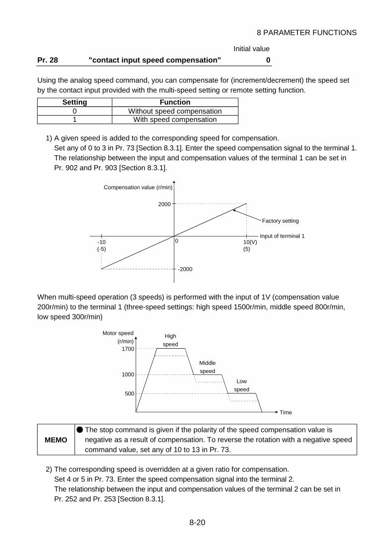
8 PARAMETER FUNCTIONS
8-20
Initial value
Pr. 28 "contact input speed compensation" 0
Using the analog speed command, you can compensate for (increment/decrement) the speed setby the contact input provided with the multi-speed setting or remote setting function.
Setting Function0 Without speed compensation1 With speed compensation
1) A given speed is added to the corresponding speed for compensation.Set any of 0 to 3 in Pr. 73 [Section 8.3.1]. Enter the speed compensation signal to the terminal 1.The relationship between the input and compensation values of the terminal 1 can be set inPr. 902 and Pr. 903 [Section 8.3.1].
-10(-5)
10(V)(5)
2000
-2000
0Input of terminal 1
Compensation value (r/min)
Factory setting
When multi-speed operation (3 speeds) is performed with the input of 1V (compensation value200r/min) to the terminal 1 (three-speed settings: high speed 1500r/min, middle speed 800r/min,low speed 300r/min)
1700
1000
500
Time
Motor speed
(r/min)High
speed
Middle
speed
Low
speed
MEMO
The stop command is given if the polarity of the speed compensation value isnegative as a result of compensation. To reverse the rotation with a negative speedcommand value, set any of 10 to 13 in Pr. 73.
2) The corresponding speed is overridden at a given ratio for compensation.Set 4 or 5 in Pr. 73. Enter the speed compensation signal into the terminal 2.The relationship between the input and compensation values of the terminal 2 can be set inPr. 252 and Pr. 253 [Section 8.3.1].

8 PARAMETER FUNCTIONS
8-21
8
8.4 Selection of the Control Circuit Contact Input Terminal Functions
Initial value
Pr. 17 "MRS input selection" 0
Select the operation logic of the MRS signal assigned to the control circuit terminal.
Wiring ExamplesSetting Function
Sink logic Source logic
0Output shut offwhen terminals areclosed.
MRS
SD
Drive unit
PC
MRS
Drive unit
2Output shut offwhen terminals areopened.
MRS
SD
Drive unit
PC
MRS
Drive unit

8 PARAMETER FUNCTIONS
8-22
Initial value
Pr. 180 "RL terminal function selection" 0
Pr. 181 "RM terminal function selection" 1
Pr. 182 "RH terminal function selection" 2
Pr. 183 "RT terminal function selection" 3
Pr. 184 "AU terminal function selection" 4
Pr. 185 "JOG terminal function selection" 5
Pr. 186 "CS terminal function selection" 8
Pr. 187 "MRS terminal function selection" 24
By setting the corresponding parameter values, you can select/change the functions of the controlcircuit contact input terminals.The following table lists the values and functions that may be set to the parameters.
Setting Signal Name Function0 RL1 RM2 RH
Operation using multi-speed (speeds 1 to 7) setting or remote settingfunction
Refer to: 8.3.2 Variable-speed operation using contact input signals
3 RTSecond function
Refer to: 8.5.2 Acceleration time and deceleration time
4 AUSelection of current input speed command
Refer to: 8.3.1 Selection of the analog speed command specifications
5 JOGJOG operation mode selection
Refer to: 8.6.1 JOG operation
7 OHThe "external fault" protective function is activated when the externalcontact connected across terminals OH-SD "opens".
Refer to: Chapter 6, 6.1.1 Protective function activated
8 REXOperation using multi-speed (speeds 8 to 15) setting
Refer to: 8.3.2 Variable-speed operation using contact input signals
9 X9Third function
Refer to: 8.5.2 Acceleration time and deceleration time10 X10 For connection of high power factor converter
12 X12PU operation external interlock
Refer to: Pr. 79 [Section 8.2]
14 X14PID control operation cancel
Refer to: 8.6.3 PID control operation
16 X16PU operation-external operation switching
Refer to :Pr. 79 [Section 8.2]
24 MRSSame function as that of the contact input terminal MRS.
Refer to: Chapter 3, 3.3.1 Terminals9999 No function
MEMO
When the remote setting function (Pr. 59 = 1, 2 [Section 8.3.2]) has been set, theRL, RM and RH terminals provide the remote setting function.
You can assign one function to two or more terminals. In this case, the function isperformed by the logical add of the terminal inputs.
The priority of the speed commands is in order of JOG, multi-speed operation,current input (AU) operation, and voltage input operation.

8 PARAMETER FUNCTIONS
8-23
8
Initial value
Pr. 188 "RES terminal operation selection" 0
Select the reset operation of the RES terminal. Reset operation is performed when RES-SD (sinklogic) are shorted more than 0.1s.
Setting Name Function
0 CPU reset
The cumulative thermal value of the electronic overcurrent protectionand the retry count [Section 6.1.1] stored during operation areinitialized. The alarm status is canceled. Performing reset operationduring operation coasts the motor, and canceling the reset restarts themotor.
1Alarm/CPU reset
The alarm status is canceled. At this time, the cumulative thermal valueof the electronic overcurrent protection and the retry count are alsoinitialized.A reset input is not accepted during normal operation.
MEMO
The reset operation performed using the STOP/RESET key of the operation panelor FR-PU04 parameter unit will result in an alarm reset regardless of the Pr. 188setting. The Pr. 188 setting does not return to the initial value if parameter clear or all clear[Section 4.3] is performed.
Initial value
Pr. 189 "STF, STR terminal operation selection" 0
You can turn the terminal STF into a start/stop function and the terminal STR into a direction ofrotation direction switching function.
Forward RotationOperation
Reverse RotationOperation
StopSetting
STF STR STF STR STF STR
OFF OFF0 ON OFF OFF ON
ON ON
OFF OFF1 ON OFF ON ON
OFF ON

8 PARAMETER FUNCTIONS
8-24
8.5 Setting of the Operation Pattern
8.5.1 Running speed region
Initial value
Pr. 1 "maximum speed" 3000
Pr. 2 "minimum speed" 0
Pr. Setting Range Unit
1 0 to 3000 r/min
2 0 to 3000 r/min
You can set the upper and lower limits of the motor speed.If the speed command entered is more than the maximum speed set in Pr. 1, the running speed isclamped at the maximum speed.If the speed command entered is less than the minimum speed set in Pr. 2, the running speed willnot fall below the minimum speed.If the speed command is not input, turning "ON" the start signal will start operation at the minimumspeed.
Pr. 1
Pr. 2
0
Motor speed
Speed command value
or like5, 10V, 20mA
Initial value
Pr. 13 "minimum motor speed" 100
Setting Range Unit
40 to 100 r/min
The motor stops in response to any speed command less than the value set in Pr. 13. When thespeed command rises to or above the preset value, the motor speed increases in accordance withthe acceleration time set in Pr. 7 [Section 8.5.2].
NOTICE Use the Pr. 13 setting at 100r/min. If that value is set to less than 100r/min, a largecurrent may flow depending on the load, resulting in an alarm stop.

8 PARAMETER FUNCTIONS
8-25
8
Initial value
Pr. 31 to 36 "speed command jumps 1A to 3B" 9999
Pr.A point
sideB point
sideSetting Range Unit
31 32 0 to 3000, 9999 r/min33 34 0 to 3000, 9999 r/min35 36 0 to 3000, 9999 r/min
You can set up to three speed areas where continuous operation will be disabled. You can avoidcontinuous operation at the speed at which resonance will occur due to the natural frequency of amechanical system. When the speed command within the setting range is input, continuousoperation is performed at the preset speed of value A.Setting "9999" in the parameter makes this function invalid.
Pr. 31(1A)Pr. 32(1B)
Pr. 33(2A)
Pr. 34(2B)
Pr. 35(3A)
Pr. 36(3B)Speed jump
Run
nin
g sp
eed
<Setting example 1>When you set 500 (r/min) in Pr. 31 and 700 (r/min) in Pr. 32, the running speed is 500 (r/min) ifthe speed command is between the range of 500 to 700 (r/min).
<Setting example 2>When you set 700 (r/min) in Pr. 31 and 500 (r/min) in Pr. 32, the running speed is 700 (r/min) ifthe speed command is between the range of 500 to 700 (r/min).
MEMO
The "speed command jump" function is designed to disable continuous operationbetween the preset A and B points. When the running speed command is outside A-B, the speed varies between A and B in accordance with the presetacceleration/deceleration time.
A setting less than the Pr. 13 value will be a stop (0r/min) setting.
Initial value
Pr. 78 "reverse rotation prevention selection" 0
You can fix the direction of rotation.
Setting Function
0Forward or reverse rotation operation is performed in accordance with the forwardor reverse rotation command.
1Forward rotation operation is performed in accordance with the forward rotationcommand. Operation is stopped in response to the reverse rotation command.
2Reverse rotation operation is performed in accordance with the reverse rotationcommand. Operation is stopped in response to the forward rotation command.

8 PARAMETER FUNCTIONS
8-26
8.5.2 Acceleration time and deceleration time
Initial valuePr. 7 "acceleration time" 5
Pr. 8 "deceleration time" 5
Pr. 20 "acceleration/deceleration reference speed" 2000
Pr. 21 "acceleration/deceleration time unit" 0
Pr. Pr. 21 Setting Range Unit0 0.0 to 3600
7, 81 0.00 to 360.0
s
20 1 to 3000 r/min
In Pr. 7, set the time required to increase the speed from a start to the speed set in Pr. 20.In Pr. 8, set the time required to decrease the speed from the speed set in Pr. 20 to a stop.In Pr. 21, you can change the setting unit.
Pr. 7 Pr. 8
Pr. 20
Time
Spe
ed
Running speed
Braking voltage or coasting to stopRefer to: 8.5.4 Stopping operation
When the FR-DU04 operation panel is used, the minimum setting increments of the accelerationand deceleration times vary with the acceleration and deceleration time settings.
Minimum Setting IncrementsPr. Setting of less than
100Setting between 100and less than 1000
Setting of 1000 ormore
Unit
0 0.1 11 0.01
0.1 s
MEMO
The minimum value of acceleration/deceleration time is 0.08s. Anyacceleration/deceleration time setting of less than 0.08 is handled as 0.08s. The upper limit of acceleration time at up to 100r/min is 5s (converted at referencespeed 2000r/min). When the acceleration time setting is greater than 5s, therefore,the acceleration time required to reach the acceleration/deceleration referencespeed is represented by the following expression and is shorter than the presetacceleration time:
Required acceleration time = 0.25 + T1T1 = (preset speed command - 100) × Pr. 7 setting/Pr. 20 setting
The value less than the Pr. 10 setting will voltage-brake or coast the motor to a stop.Therefore, the deceleration time required to decrease the speed from the speed setin Pr. 20 to the speed set in Pr. 10 is as follows:
Required deceleration time = Pr. 8 setting × (Pr. 20 setting - Pr. 10 setting)/Pr. 20 setting
A too short acceleration/deceleration time setting can cause an abnormal stop dueto overload, overcurrent or overvoltage. Make a setting which will not displayoverload on the operation panel. Rapid acceleration of less than 0.2s may make the starting torque insufficient.
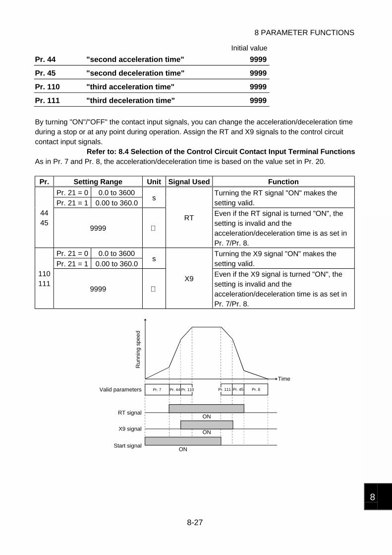
8 PARAMETER FUNCTIONS
8-27
8
Initial value
Pr. 44 "second acceleration time" 9999
Pr. 45 "second deceleration time" 9999
Pr. 110 "third acceleration time" 9999
Pr. 111 "third deceleration time" 9999
By turning "ON"/"OFF" the contact input signals, you can change the acceleration/deceleration timeduring a stop or at any point during operation. Assign the RT and X9 signals to the control circuitcontact input signals.
Refer to: 8.4 Selection of the Control Circuit Contact Input Terminal FunctionsAs in Pr. 7 and Pr. 8, the acceleration/deceleration time is based on the value set in Pr. 20.
Pr. Setting Range Unit Signal Used Function
Pr. 21 = 0 0.0 to 3600
Pr. 21 = 1 0.00 to 360.0s
Turning the RT signal "ON" makes thesetting valid.
4445
9999 RT
Even if the RT signal is turned "ON", thesetting is invalid and theacceleration/deceleration time is as set inPr. 7/Pr. 8.
Pr. 21 = 0 0.0 to 3600
Pr. 21 = 1 0.00 to 360.0s
Turning the X9 signal "ON" makes thesetting valid.
110111
9999 X9
Even if the X9 signal is turned "ON", thesetting is invalid and theacceleration/deceleration time is as set inPr. 7/Pr. 8.
Pr. 7 Pr. 44 Pr. 110 Pr. 111 Pr. 45 Pr. 8
ON
ON
ON
Time
Run
nin
g s
pee
d
Valid parameters
RT signal
X9 signal
Start signal

8 PARAMETER FUNCTIONS
8-28
8.5.3 Acceleration/deceleration patterns
Initial value
Pr. 29 "acceleration/deceleration pattern" 0
You can change the acceleration/deceleration pattern.
Setting Name Function Time vs. Speed
0Linearacceleration/deceleration
In this pattern, the speed varies withthe time constantly.
tTime
Ru
nnin
g
spe
ed (
r/m
in)
[Linear acceleration/deceleration]
1S-shapedacceleration/deceleration A
In this pattern, the speed varies froma start to the maximum speed withthe rated speed given at aninflection point (fb).In this setting, motor torquereduction in a constant-output regionis taken into consideration, e.g.application to machine tool spindles.
tTimeR
unn
ing
spee
d (r
/min
)
fb2000
[S-shaped acceleration/deceleration A]
2S-shapedacceleration/deceleration B
This pattern always ranges from thepresent running speed and a newlyset speed.Since an acceleration/decelerationshock is eased, this pattern has aneffect on the prevention of cargocollapse as in a conveyor. t
f1
f2
Time
Ru
nnin
g
spee
d (
r/m
in)
[S-shaped acceleration/deceleration B]
MEMO When Pr. 29 = 1, the acceleration/deceleration time setting reference speed is notas set in Pr. 20 [Section 8.5.2] "acceleration/deceleration reference speed" but isthe rated speed of the motor.
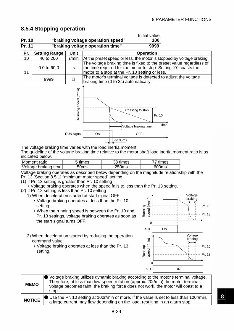
8 PARAMETER FUNCTIONS
8-29
8
8.5.4 Stopping operationInitial value
Pr. 10 "braking voltage operation speed" 100Pr. 11 "braking voltage operation time" 9999
Pr. Setting Range Unit Operation10 40 to 200 r/min At the preset speed or less, the motor is stopped by voltage braking.
0.0 to 60.0 sThe voltage braking time is fixed to the preset value regardless ofthe time required for the motor to stop. Setting "0" coasts themotor to a stop at the Pr. 10 setting or less.11
9999 The motor's terminal voltage is detected to adjust the voltagebraking time (0 to 3s) automatically.
Pr. 10
ON OFF
5 to 35ms
RUN signal
Run
ning
spe
ed (
r/m
in)
Coasting to stop
Voltage braking time Time
The voltage braking time varies with the load inertia moment.The guideline of the voltage braking time relative to the motor shaft-load inertia moment ratio is asindicated below.Moment ratio 5 times 38 times 77 timesVoltage braking time 50ms 250ms 600msVoltage braking operates as described below depending on the magnitude relationship with thePr. 13 [Section 8.5.1] "minimum motor speed" setting.(1) If Pr. 13 setting is greater than Pr. 10 setting
• Voltage braking operates when the speed falls to less than the Pr. 13 setting.(2) If Pr. 13 setting is less than Pr. 10 setting
1) When deceleration started at start signal OFF• Voltage braking operates at less than the Pr. 10
setting.• When the running speed is between the Pr. 10 and
Pr. 13 settings, voltage braking operates as soon asthe start signal turns OFF.
ONSTF
0
Pr. 10
Pr. 13Run
ning
spe
ed (
r/m
in) braking
Voltage
2) When deceleration started by reducing the operationcommand value• Voltage braking operates at less than the Pr. 13
setting.
ONSTF
0
Pr. 10
Pr. 13
Voltage
Ru
nnin
g
spe
ed (
r/m
in) braking
MEMO
Voltage braking utilizes dynamic braking according to the motor's terminal voltage.Therefore, at less than low-speed rotation (approx. 20r/min) the motor terminalvoltage becomes faint, the braking force does not work, the motor will coast to astop.
NOTICE Use the Pr. 10 setting at 100r/min or more. If the value is set to less than 100r/min,a large current may flow depending on the load, resulting in an alarm stop.
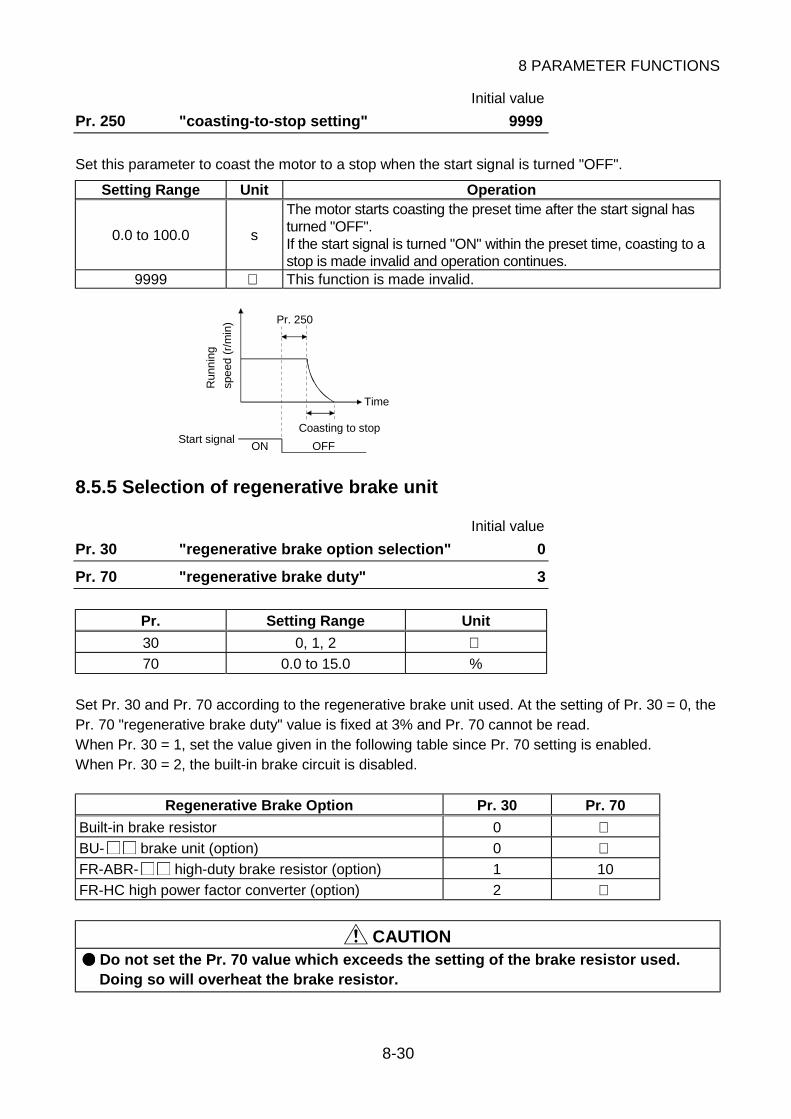
8 PARAMETER FUNCTIONS
8-30
Initial value
Pr. 250 "coasting-to-stop setting" 9999
Set this parameter to coast the motor to a stop when the start signal is turned "OFF".
Setting Range Unit Operation
0.0 to 100.0 s
The motor starts coasting the preset time after the start signal hasturned "OFF".If the start signal is turned "ON" within the preset time, coasting to astop is made invalid and operation continues.
9999 This function is made invalid.
ON OFF
Pr. 250
Start signal
Run
nin
g
spe
ed (
r/m
in)
Coasting to stop
Time
8.5.5 Selection of regenerative brake unit
Initial value
Pr. 30 "regenerative brake option selection" 0
Pr. 70 "regenerative brake duty" 3
Pr. Setting Range Unit
30 0, 1, 2 70 0.0 to 15.0 %
Set Pr. 30 and Pr. 70 according to the regenerative brake unit used. At the setting of Pr. 30 = 0, thePr. 70 "regenerative brake duty" value is fixed at 3% and Pr. 70 cannot be read.When Pr. 30 = 1, set the value given in the following table since Pr. 70 setting is enabled.When Pr. 30 = 2, the built-in brake circuit is disabled.
Regenerative Brake Option Pr. 30 Pr. 70
Built-in brake resistor 0 BU- brake unit (option) 0 FR-ABR- high-duty brake resistor (option) 1 10
FR-HC high power factor converter (option) 2
CAUTION Do not set the Pr. 70 value which exceeds the setting of the brake resistor used.Doing so will overheat the brake resistor.

8 PARAMETER FUNCTIONS
8-31
8
8.5.6 Stall prevention operation level
Initial value
Pr. 22 "stall prevention operation level" 150
Setting Range Unit Remarks0, 150 % When 0 is set, the stall prevention function is not activated.
When the output current reaches the Pr. 22 setting, the speed is varied with the running status tosuppress the torque. The setting is based on the rated motor current.When the stall prevention function is activated, OL appears on the screen of the operation panel orFR-PU04 parameter unit. That the stall prevention function has been activated can be exported asOL signal from the terminal.
Refer to: 8.7.2 Selection of the control circuit output terminal functions
Initial value
Pr. 156 "stall prevention operation selection" 1
You can select whether or not to perform stall prevention operation according to the operationstatus.
Operation Status Setting
AccelerationConstant
speedDeceleration Region
When OL signal isoutput to continue
operation
When E. OLT isdisplayed to stop
operation Yes Yes Yes 1 17 No Yes Yes 3 19 Yes No Yes 5 21 No No Yes 7 23 Yes Yes No 9 25 No Yes No 11 27 Yes No No 13 29 No No No
Driving andregenerative
15 31 Yes Yes Yes Driving
No No NoSetting
disabled101 Regenerative
Refer to: Chapter 6, 6.1.1 Protective function activated8.7.2 Selection of the control circuit outputterminal functions
MEMO
If the stall prevention function is activated during acceleration or deceleration, theacceleration or deceleration time [Section 8.5.2] will be longer than the setting.When the travel of a machine or the like is determined by the acceleration ordeceleration time, the travel will increase due to the operation of the stall preventionfunction. If the stall prevention function is activated during constant speed operation, therunning speed may vary abruptly.
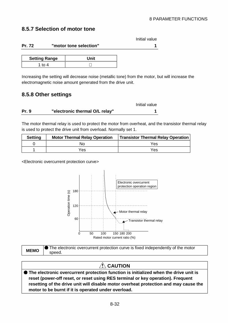
8 PARAMETER FUNCTIONS
8-32
8.5.7 Selection of motor tone
Initial value
Pr. 72 "motor tone selection" 1
Setting Range Unit
1 to 4
Increasing the setting will decrease noise (metallic tone) from the motor, but will increase theelectromagnetic noise amount generated from the drive unit.
8.5.8 Other settings
Initial value
Pr. 9 "electronic thermal O/L relay" 1
The motor thermal relay is used to protect the motor from overheat, and the transistor thermal relayis used to protect the drive unit from overload. Normally set 1.
Setting Motor Thermal Relay Operation Transistor Thermal Relay Operation
0 No Yes
1 Yes Yes
<Electronic overcurrent protection curve>
180
120
60
0 50 100 150 180 200Rated motor current ratio (%)
Ope
ratio
n tim
e (s
)
Motor thermal relay
Transistor thermal relay
protection operation regionElectronic overcurrent
MEMO The electronic overcurrent protection curve is fixed independently of the motorspeed.
CAUTION The electronic overcurrent protection function is initialized when the drive unit isreset (power-off reset, or reset using RES terminal or key operation). Frequentresetting of the drive unit will disable motor overheat protection and may cause themotor to be burnt if it is operated under overload.

8 PARAMETER FUNCTIONS
8-33
8
Pr. 84 "rated motor speed" Read-only
The rated speed of the motor used with the drive unit is displayed. This parameter is for read-onlyand its value cannot be changed.
Initial value
Pr. 244 "cooling fan operation selection" 0
When the drive unit has a built-in cooling fan, you can select the operation of the cooling fan.
Setting Operation
0 While the drive unit power is on, the cooling fan keeps running.
1While the motor is operating, the cooling fan keeps running. While the motor is at astop, the cooling fan is stopped according to the temperature of the drive unit.
MEMO
If the cooling fan stops due to a failure, the "FN" alarm indication appears on theoperation panel.
Refer to: Chapter 6, 6.1.2 Alarm function activated That the cooling fan has stopped due to a failure can be exported as an alarmsignal.
Refer to: 8.7.2 Selection of the control circuit output terminal functions When Pr. 244 = 1, the alarm function is activated if the fan starts running during thefan "OFF" command.
Initial value
Pr. 990 "buzzer control" 1
You can make the buzzer "beep" when you press any key of the operation panel or FR-PU04parameter unit.
Setting Function
0 Without beep
1 With beep
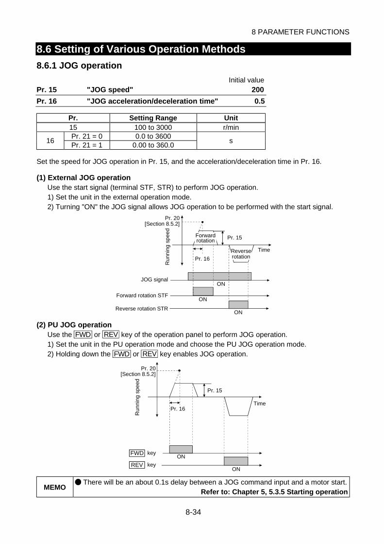
8 PARAMETER FUNCTIONS
8-34
8.6 Setting of Various Operation Methods
8.6.1 JOG operation
Initial valuePr. 15 "JOG speed" 200
Pr. 16 "JOG acceleration/deceleration time" 0.5
Pr. Setting Range Unit15 100 to 3000 r/minPr. 21 = 0 0.0 to 3600
16Pr. 21 = 1 0.00 to 360.0
s
Set the speed for JOG operation in Pr. 15, and the acceleration/deceleration time in Pr. 16.
(1) External JOG operationUse the start signal (terminal STF, STR) to perform JOG operation.1) Set the unit in the external operation mode.2) Turning "ON" the JOG signal allows JOG operation to be performed with the start signal.
Pr. 20
Pr. 15
ON
ON
ON
Time
Ru
nnin
g s
pee
d
Pr. 16
[Section 8.5.2]
JOG signal
Forward rotation STF
Reverse rotation STR
rotationReverse
Forwardrotation
(2) PU JOG operationUse the FWD or REV key of the operation panel to perform JOG operation.1) Set the unit in the PU operation mode and choose the PU JOG operation mode.2) Holding down the FWD or REV key enables JOG operation.
Pr. 16
Pr. 15
ON
ON
FWD
REV
Ru
nnin
g s
pee
d
key
key
Time
Pr. 20[Section 8.5.2]
MEMO There will be an about 0.1s delay between a JOG command input and a motor start.
Refer to: Chapter 5, 5.3.5 Starting operation

8 PARAMETER FUNCTIONS
8-35
8
8.6.2 Communication operation from the PU connector
Initial valuePr. 117 "station number" 0
Pr. 118 "communication speed" 192
Pr. 119 "stop bit length/data length" 1
Pr. 120 "parity check presence/absence" 2
Pr. 121 "number of communication retries" 1
Pr. 122 "communication check time interval" 0
Pr. 123 "waiting time setting" 9999
Pr. 124 "CR-LF presence/absence selection" 1
Make settings necessary for performing RS-485 communication operation from the PU connectorusing a personal computer or similar equipment.After you have made parameter settings, reset the CPU or switch power "OFF" once. Switchingpower on again makes the parameter values valid.
Pr. Setting Range Unit Description
117 0 to 31 Station Set the station number of the drive unit.48 4800bps96 9600bps118
192 19200bps0 Stop bit length 1 bit/data length 8 bits1 Stop bit length 2 bits/data length 8 bits10 Stop bit length 1 bit/data length 7 bits
119
11 Stop bit length 2 bits/data length 7 bits0 None1 Odd parity present1202 Even parity present
0 to 10 TimesSet the number of retries to be made at occurrence of a datareceive error. If errors in excess of the setting occur consecutively,E. PUE appears, resulting in an alarm stop.
121
9999 Assigning the LF signal to the control circuit output terminal allowsa communication error occurrence signal to be output. Occurrenceof a communication error will not cause an alarm stop.
0 No communication. (Communication operation not performed)
0.01 to 999.8 sWhen a no-communication status time reaches the setting,E. PUE appears and an alarm stop occurs.
122
9999 No-communication status time check is not made.
0 to 150 Set the waiting time from when the drive unit has received data untilit gives a reply. The actual waiting time is (setting × 10 + 12)ms.123
9999 Set the waiting time using communication data.0 Without CR (carriage return), LF (line feed)1 With CR (carriage return)1242 With CR (carriage return)/LF (line feed)

8 PARAMETER FUNCTIONS
8-36
(1) Communication specifications
Conforming standard RS-485 Standard conformanceNumber of units connected 1 : N (max. 32 units)
Communication speed Selected between 19200, 9600 and 4800bpsControl protocol Asynchronous
Communication method Half-duplexCharacter system ASCII (7 bits/8 bits) selectableStop bit length Selectable between 1 bit and 2 bits.Terminator CR/LF presence/absence selectableParity check Selectable between presence (even/odd) and absenceSumcheck Presence
Com
munic
atio
ndata
Waiting time setting Selectable between presence and absence
(2) Communication operation functions
Setting a value other than 0 in Pr. 122 enables RS-485 communication with the computerconnected to the PU connector, allowing you to make operation and parameter settings.
Setting Item Description
Start Give a forward rotation operation, reverse rotation operation or stop command.Speed setting Set the running speed.
MonitorYou can read the motor speed, motor current, output voltage, drive unit fault,or control circuit output terminal assignment function activated.
Opera
tion
ResetUsed to reset the drive unit. A reset from the terminal RES is also valid.Reset operation is performed as set in Pr. 188 [Section 8.4].
Parameter write andread
You can change or read each parameter value.Parameter write is performed as set in Pr. 77 [Section 8.1].
You can select the operation mode through communication.
Operation Mode Description
Communicationoperation mode
Operation and parameter write/read are performed through communication.
External operationmode
Start and speed setting are made using the input signals from the controlcircuit terminals. Setting external/PU combined operation 1 in the operationmode selection (Pr. 79 [Section 8.2]) enables speed setting throughcommunication. Though monitor and parameter read can be performedthrough communication, parameter write cannot be performed.
The following operation is performed when a communication operation fault occurs.
OperationLocation of FaultOccurrence Communication operation mode External operation mode
Motor operation stopped Motor operation stoppedDrive unit
Communication continued Communication continuedWhether motor operation is stoppedor continued depends on the Pr. 75
[Section 8.2] setting.Motor operation continued
Communication(Computer or
communicationcable) Communication stopped Communication stopped

8 PARAMETER FUNCTIONS
8-37
8
NOTICE
Communication operation is performed in response to the communication requestfrom the personal computer. Therefore, if communication is suspended due to acommunication cable break or computer failure during operation, the drive unitcannot detect a fault and stop operation. However, operation is brought to an alarmstop (E. PUE) if the time set as the communication check time interval has elapsed.To stop operation before the time set as the communication check time interval isreached, reset the CPU using the RES terminal or switch power off. The motor willthen coast to a stop.
(3) Communication data and communication protocol
The following table provides the communication data and communication protocol between thecomputer and drive unit.
CommunicationData Description
Computer sendingdata
The computer gives a communication request to the drive unit in accordancewith the user program
Drive unit returningdata
In response to the communication request from the computer, the drive unitreturns data to the computer.
Computer replyingdata
The computer replies to the drive unit whether it could receive the drive unitreturning data properly or not.
Communication protocol in write mode (when drive unit writes data)
12ms
Drive unit
Drive unit
Computer
Computer12ms or more
Time
Computersending data
returning dataDrive unit
Computersending data
Waiting time
MEMO
On detection of an error at the receipt of the data sent by the computer, the driveunit returns an error code, making the sent data invalid. Data is retransmitted(resending of data by the computer) when an error occurs. Setting of Pr. 121 allowsthe drive unit to come to an alarm stop if consecutive errors occur in the computersending data.
Communication protocol in read mode (when data is read from drive unit)
12ms
Drive unit
Drive unitTime
Computer Waiting time
12ms or more 12ms or moreComputer
sending dataComputer
returning dataDrive unit
Computerreplying data sending data
Computer
MEMO
On detection of an error at the receipt of the drive unit returning data, an erroroccurrence is sent using the computer replying data. In this case, the drive unitmakes retry transmission (resending of drive unit returning data). Setting of Pr. 121allows the drive unit to come to an alarm stop if consecutive errors occur in thecomputer replying data.
Approximately 12ms plus waiting time after the drive unit has completed receiving the data sent bythe computer, the drive unit sends the drive unit returning data to the computer.Set the waiting time in Pr. 123 to match the answerable time of the computer.
MEMO The waiting time may also be set using the computer sending data. In this case, set9999 in Pr. 123.
NOTICE Always allow for more than 12ms to pass after sending or receiving a messagebefore initiating another send message from the computer.
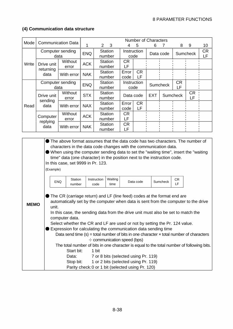
8 PARAMETER FUNCTIONS
8-38
(4) Communication data structure
Number of CharactersMode Communication Data
1 2 3 4 5 6 7 8 9 10Computer sending
dataENQ
Stationnumber
Instructioncode
Data code SumcheckCRLF
Withouterror
ACKStationnumber
CRLF
Write Drive unitreturning
data With error NAKStationnumber
Errorcode
CRLF
Computer sendingdata
ENQStationnumber
Instructioncode
SumcheckCRLF
Withouterror
STXStationnumber
Data code EXT SumcheckCRLF
Drive unitsending
data With error NAXStationnumber
Errorcode
CRLF
Withouterror
ACKStationnumber
CRLF
Read
Computerreplying
data With error NAKStationnumber
CRLF
MEMO
The above format assumes that the data code has two characters. The number ofcharacters in the data code changes with the communication data. When using the computer sending data to set the "waiting time", insert the "waitingtime" data (one character) in the position next to the instruction code.
In this case, set 9999 in Pr. 123.
ENQ Sumcheck
(Example)
Station
number
Instruction
code
Waiting
timeData code
CRLF
The CR (carriage return) and LF (line feed) codes at the format end areautomatically set by the computer when data is sent from the computer to the driveunit.In this case, the sending data from the drive unit must also be set to match thecomputer data.Select whether the CR and LF are used or not by setting the Pr. 124 value. Expression for calculating the communication data sending time
Data send time (s) = total number of bits in one character × total number of characters communication speed (bps)
The total number of bits in one character is equal to the total number of following bits.Start bit: 1 bitData: 7 or 8 bits (selected using Pr. 119)Stop bit: 1 or 2 bits (selected using Pr. 119)Parity check:0 or 1 bit (selected using Pr. 120)

8 PARAMETER FUNCTIONS
8-39
8
(5) Explanation of communication data structure
1) Control codesThe following table lists the ASCII codes and their definitions of the control code names whichare set at the beginning, end and like of the format.
Signal Name ASCII Code Description
STX H02 Start of Text (Start of data)ETX H03 End of Text (End of data)ENQ H05 Enquiry (Communication request)ACK H06 Acknowledge (No data error detected)LF H0A Line FeedCR H0D Carriage Return
NAK H15 Negative Acknowledge (Data error detected)
2) Station numberSpecify the station number of the drive unit used for communication with the computer.Specify the drive unit station number within the range H00 to H1F (stations 0 to 31) inhexadecimal.The communication data is converted into ASCII automatically.
Example: H00 (binary) H3030 (ASCII)
3) Instruction codes and data codesSet the instruction code and data code which correspond to the operation mode, operation orparameter write or read. The communication data is converted into ASCII automatically.
i) Setting the operation mode
Setting ItemMode
InstructionCode
Data Codes and Definitions Charactercount
Write HFBH0000: SpareH0001: Eternal operation modeH0002: Communication operation mode
4
Operation mode
Read H7BH0000: SpareH0001: Eternal operation modeH0002: Communication operation mode
4
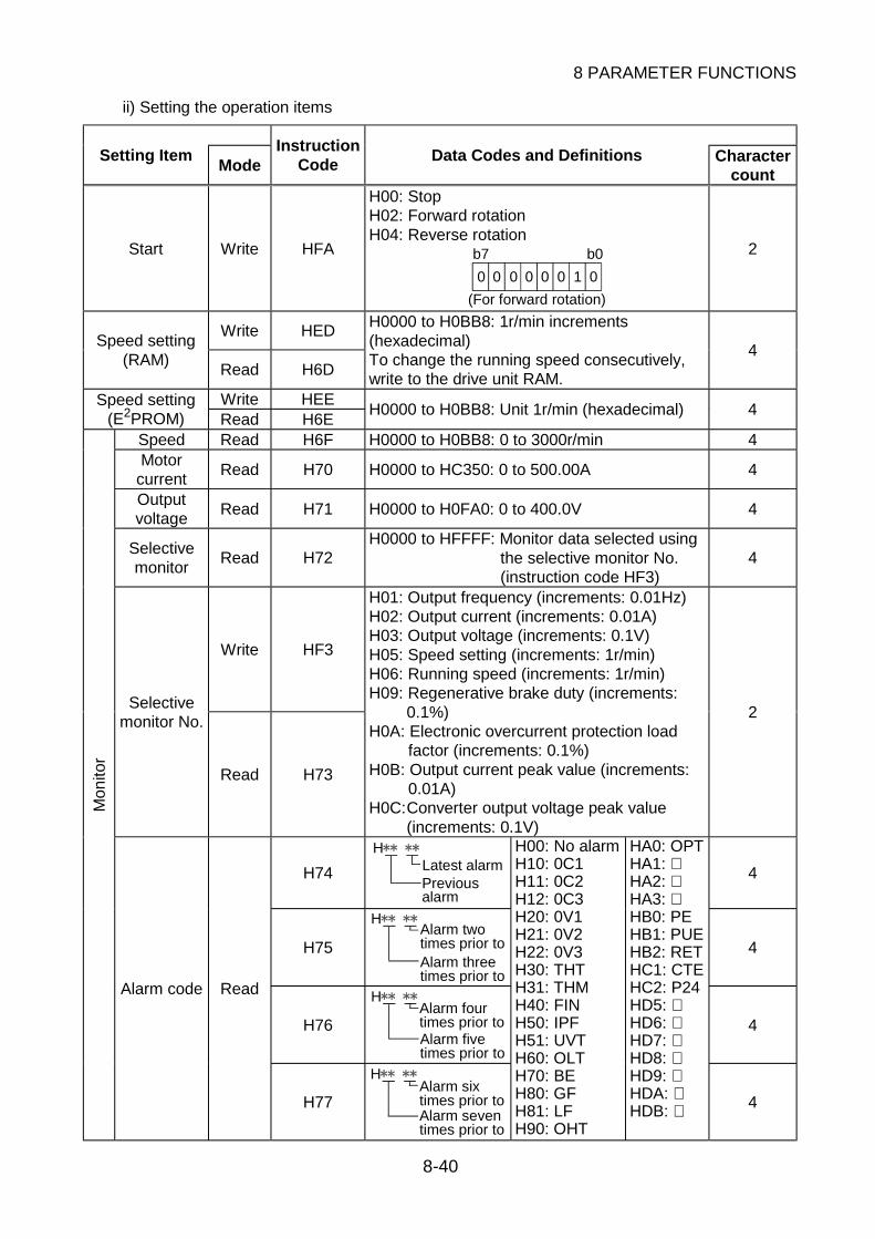
8 PARAMETER FUNCTIONS
8-40
ii) Setting the operation items
Setting ItemMode
InstructionCode
Data Codes and Definitions Charactercount
Start Write HFA
H00: StopH02: Forward rotationH04: Reverse rotation
0 0 01000 0
b7 b0
(For forward rotation)
2
Write HEDSpeed setting
(RAM)Read H6D
H0000 to H0BB8: 1r/min increments(hexadecimal)To change the running speed consecutively,write to the drive unit RAM.
4
Write HEESpeed setting(E2PROM) Read H6E
H0000 to H0BB8: Unit 1r/min (hexadecimal) 4
Speed Read H6F H0000 to H0BB8: 0 to 3000r/min 4Motor
currentRead H70 H0000 to HC350: 0 to 500.00A 4
Outputvoltage
Read H71 H0000 to H0FA0: 0 to 400.0V 4
Selectivemonitor
Read H72H0000 to HFFFF: Monitor data selected using
the selective monitor No.(instruction code HF3)
4
Write HF3
Selectivemonitor No.
Read H73
H01: Output frequency (increments: 0.01Hz)H02: Output current (increments: 0.01A)H03: Output voltage (increments: 0.1V)H05: Speed setting (increments: 1r/min)H06: Running speed (increments: 1r/min)H09: Regenerative brake duty (increments:
0.1%)H0A: Electronic overcurrent protection load
factor (increments: 0.1%)H0B: Output current peak value (increments:
0.01A)H0C:Converter output voltage peak value
(increments: 0.1V)
2
H74
HLatest alarmPreviousalarm
4
H75
H
times prior toAlarm two
times prior toAlarm three
4
H76
H
times prior toAlarm four
times prior toAlarm five
4
Mon
itor
Alarm code Read
H77
H
times prior toAlarm six
times prior toAlarm seven
H00: No alarmH10: 0C1H11: 0C2H12: 0C3H20: 0V1H21: 0V2H22: 0V3H30: THTH31: THMH40: FINH50: IPFH51: UVTH60: OLTH70: BEH80: GFH81: LFH90: OHT
HA0: OPTHA1: HA2: HA3: HB0: PEHB1: PUEHB2: RETHC1: CTEHC2: P24HD5: HD6: HD7: HD8: HD9: HDA: HDB: 4

8 PARAMETER FUNCTIONS
8-41
8
Setting ItemMode
InstructionCode
Data Codes and Definitions Charactercount
Mon
itor
Drive unitstatus
Read H7A
H01: Function assigned to RUN terminal isactivated
H02: During forward rotation (STF terminalsignal ON)
H04: During reverse rotation (STR terminalsignal ON)
H08: Function assigned to SU terminal isactivated
H10: Function assigned to OL terminal isactivated
H20: Function assigned to IPF terminal isactivated
H40: Function assigned to FU terminal isactivated
H80: Function assigned to ABC terminal isactivated
2
Reset Write HFD
H9696: The drive unit is reset.In this case, the drive unit returningdata is not returned. After a reset, waitfor more than 100ms and send thecomputer sending data.
4
Alarm codebatch-clear
Write HF4H9696: Eight alarms stored as a history are all
cleared.4
MEMO Once written, the setting of the HF3 instruction code is held, but is cleared to "0"when the drive unit is reset or all clear is performed.
iii) Parameter write and readParameter write and read require the setting of the extension codes given in Appendix 1Parameter List (Numerical Order). After setting the extension code, set the instruction codegiven in Appendix 1 Parameter List (Numerical Order) and perform write or read.This function is performed as set in Pr. 77.
Setting ItemMode
InstructionCode
Data Codes and Definitions Charactercount
Write HFF
Extension codesetting
Read H7F
H00: Parameter of extension code 0 can beaccessed for read/write.
H01: Parameter of extension code 1 can beaccessed for read/write.
H02: Parameter of extension code 2 can beaccessed for read/write.
H03: Spare.H09: Parameter of extension code 9 can be
accessed for read/write.
2
WriteParameter
Read
Refer toAppendix 1Parameter
List.
H0000 to HFFFF: Parameter settings(hexadecimal)
4
MEMO Once written, the setting of the HFF instruction code is held, but is cleared to "0"when the drive unit is reset or all clear is performed.
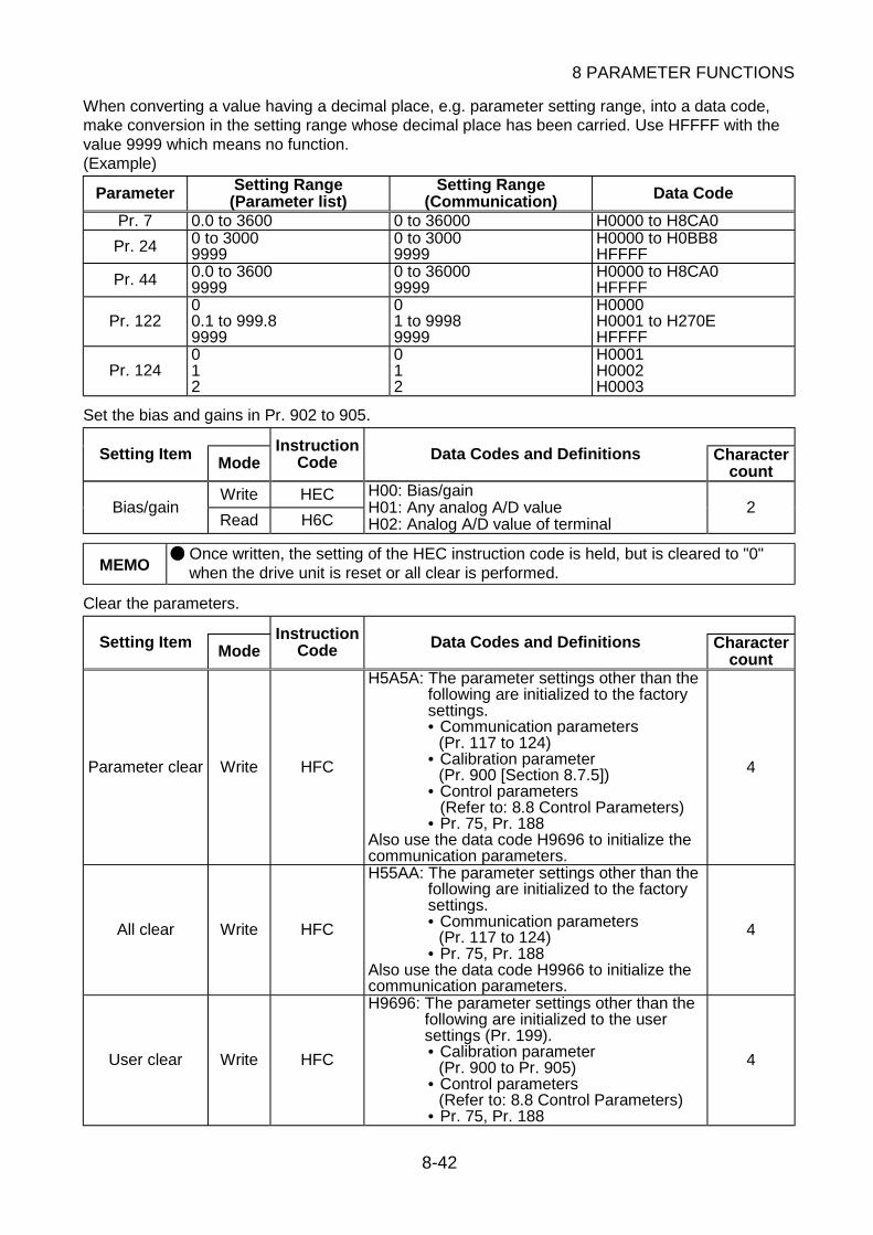
8 PARAMETER FUNCTIONS
8-42
When converting a value having a decimal place, e.g. parameter setting range, into a data code,make conversion in the setting range whose decimal place has been carried. Use HFFFF with thevalue 9999 which means no function.(Example)
Parameter Setting Range(Parameter list)
Setting Range(Communication) Data Code
Pr. 7 0.0 to 3600 0 to 36000 H0000 to H8CA0
Pr. 24 0 to 30009999
0 to 30009999
H0000 to H0BB8HFFFF
Pr. 44 0.0 to 36009999
0 to 360009999
H0000 to H8CA0HFFFF
Pr. 12200.1 to 999.89999
01 to 99989999
H0000H0001 to H270EHFFFF
Pr. 124012
012
H0001H0002H0003
Set the bias and gains in Pr. 902 to 905.
Setting Item ModeInstruction
Code Data Codes and Definitions Charactercount
Write HECBias/gain
Read H6C
H00: Bias/gainH01: Any analog A/D valueH02: Analog A/D value of terminal
2
MEMO Once written, the setting of the HEC instruction code is held, but is cleared to "0"when the drive unit is reset or all clear is performed.
Clear the parameters.
Setting Item ModeInstruction
Code Data Codes and Definitions Charactercount
Parameter clear Write HFC
H5A5A: The parameter settings other than thefollowing are initialized to the factorysettings.• Communication parameters
(Pr. 117 to 124)• Calibration parameter
(Pr. 900 [Section 8.7.5])• Control parameters
(Refer to: 8.8 Control Parameters)• Pr. 75, Pr. 188
Also use the data code H9696 to initialize thecommunication parameters.
4
All clear Write HFC
H55AA: The parameter settings other than thefollowing are initialized to the factorysettings.• Communication parameters
(Pr. 117 to 124)• Pr. 75, Pr. 188
Also use the data code H9966 to initialize thecommunication parameters.
4
User clear Write HFC
H9696: The parameter settings other than thefollowing are initialized to the usersettings (Pr. 199).• Calibration parameter
(Pr. 900 to Pr. 905)• Control parameters
(Refer to: 8.8 Control Parameters)• Pr. 75, Pr. 188
4
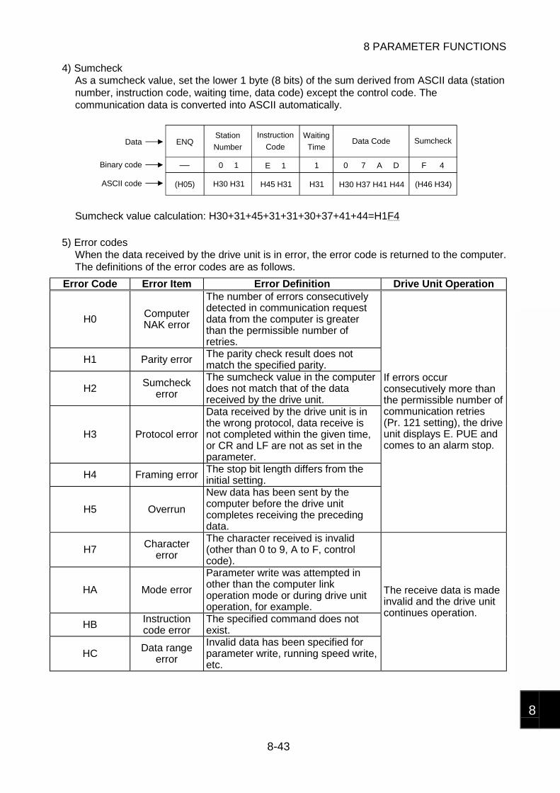
8 PARAMETER FUNCTIONS
8-43
8
4) SumcheckAs a sumcheck value, set the lower 1 byte (8 bits) of the sum derived from ASCII data (stationnumber, instruction code, waiting time, data code) except the control code. Thecommunication data is converted into ASCII automatically.
ENQ
0 1 E 1 1 0 7 A D F 4
(H05) H30 H31 H45 H31 H31 H30 H37 H41 H44 (H46 H34)
SumcheckData
Binary code
ASCII code
Station
Number
Instruction
Code
Waiting
TimeData Code
Sumcheck value calculation: H30+31+45+31+31+30+37+41+44=H1F4
5) Error codesWhen the data received by the drive unit is in error, the error code is returned to the computer.The definitions of the error codes are as follows.
Error Code Error Item Error Definition Drive Unit Operation
H0 ComputerNAK error
The number of errors consecutivelydetected in communication requestdata from the computer is greaterthan the permissible number ofretries.
H1 Parity error The parity check result does notmatch the specified parity.
H2 Sumcheckerror
The sumcheck value in the computerdoes not match that of the datareceived by the drive unit.
H3 Protocol error
Data received by the drive unit is inthe wrong protocol, data receive isnot completed within the given time,or CR and LF are not as set in theparameter.
H4 Framing error The stop bit length differs from theinitial setting.
H5 Overrun
New data has been sent by thecomputer before the drive unitcompletes receiving the precedingdata.
If errors occurconsecutively more thanthe permissible number ofcommunication retries(Pr. 121 setting), the driveunit displays E. PUE andcomes to an alarm stop.
H7 Charactererror
The character received is invalid(other than 0 to 9, A to F, controlcode).
HA Mode error
Parameter write was attempted inother than the computer linkoperation mode or during drive unitoperation, for example.
HB Instructioncode error
The specified command does notexist.
HC Data rangeerror
Invalid data has been specified forparameter write, running speed write,etc.
The receive data is madeinvalid and the drive unitcontinues operation.

8 PARAMETER FUNCTIONS
8-44
(6) Program example (Switching the operation mode to communication operation)
10 OPEN "COM1 : 9600,E,8,2,HD" AS #1
80 A$=MID$(D$,I,1) 90 A=ASC(A$) 100 S=S+A 110 NEXTI 120 D$=CHR$(&H5)+D$+RIGHT$(HEX$(S),2) 130 PRINT#1,D$ 140 GOTO 501000 REC1010 IF LOC(1)=0 THEN RETURN1020 PRINT "RECEIVE DATA"
1040 RETURN
60 S=0
40 COM(1)ON
50 D$= "01FB10002"
20 COMST1,1,1:COMST1,2,1
30 ON COM(1)GOSUB REC
70 FOR I=1 TO LEN(D$)
1030 PRINT INPUT$(LOC(1),#1)
Initial setting of input file
: Communication file opening
: Interrupt definition at data receive
: Circuit control signal (RS (ON in data-receivable status), ER (unit ready signal)) ON/OFF setting
Transmission data setting
: Interrupt enable
Sum code calculation
: Addition of control and sum codesData transmission
Interrupt data receive : Interrupt occurrence at data receive
General flowchart
Line numberInput file
initial setting
Interrupt
10to40
50
to
140
Transmissiondata processing
Data settingSum codecalculationDatatransmission
1000
to
1040
processingReceive data
Data importScreen display
NOTICE
The drive unit does not accept data from the computer if it is in error. Hence, alwaysinsert a data error retry program in the user program. Since the communication of any data, e.g. run command, monitor, is started fromthe computer, the drive unit will not return data without the computer's command.For monitoring, therefore, design the program to cause the computer to provide adata read request as required.
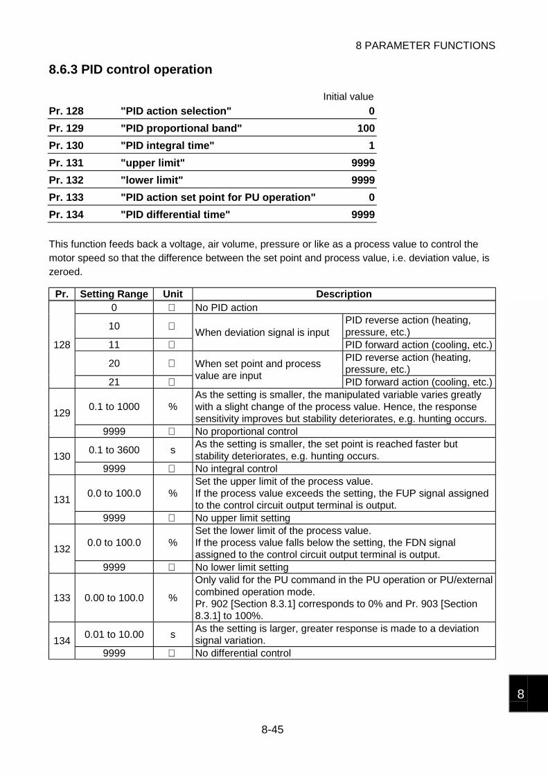
8 PARAMETER FUNCTIONS
8-45
8
8.6.3 PID control operation
Initial value
Pr. 128 "PID action selection" 0
Pr. 129 "PID proportional band" 100
Pr. 130 "PID integral time" 1
Pr. 131 "upper limit" 9999
Pr. 132 "lower limit" 9999
Pr. 133 "PID action set point for PU operation" 0
Pr. 134 "PID differential time" 9999
This function feeds back a voltage, air volume, pressure or like as a process value to control themotor speed so that the difference between the set point and process value, i.e. deviation value, iszeroed.
Pr. Setting Range Unit Description0 No PID action
10 PID reverse action (heating,pressure, etc.)
11 When deviation signal is input
PID forward action (cooling, etc.)
20 PID reverse action (heating,pressure, etc.)
128
21
When set point and processvalue are input
PID forward action (cooling, etc.)
0.1 to 1000 %As the setting is smaller, the manipulated variable varies greatlywith a slight change of the process value. Hence, the responsesensitivity improves but stability deteriorates, e.g. hunting occurs.
129
9999 No proportional control
0.1 to 3600 sAs the setting is smaller, the set point is reached faster butstability deteriorates, e.g. hunting occurs.130
9999 No integral control
0.0 to 100.0 %Set the upper limit of the process value.If the process value exceeds the setting, the FUP signal assignedto the control circuit output terminal is output.131
9999 No upper limit setting
0.0 to 100.0 %Set the lower limit of the process value.If the process value falls below the setting, the FDN signalassigned to the control circuit output terminal is output.132
9999 No lower limit setting
133 0.00 to 100.0 %
Only valid for the PU command in the PU operation or PU/externalcombined operation mode.Pr. 902 [Section 8.3.1] corresponds to 0% and Pr. 903 [Section8.3.1] to 100%.
0.01 to 10.00 sAs the setting is larger, greater response is made to a deviationsignal variation.134
9999 No differential control

8 PARAMETER FUNCTIONS
8-46
(1) PID operation setting
Using Pr. 128, select the PID action and speed command input method.
Reverse action and forward action1) Reverse action
Increases the manipulated variable if deviation X (set point - process value) is positive, anddecreases the manipulated variable if deviation is negative.
Process value
Set point
[Heating]
Process value
Deviation Set point
X>0
X<0Cold fi upHot fi down
+
-
2) Forward actionIncreases the manipulated variable if deviation X (set point - process value) is negative, anddecreases the manipulated variable if deviation is positive.
Set pointSet point
[Cooling]
Process value
Process value
Deviation
Too cold fi downHot fi up
+ X>0
X<0-
Relationships between deviation and manipulated variable
DeviationPositive Negative
Reverse actionForward action
MEMO
Basic PID control configuration
x
y
fi My
Motor
Drive Unit
Process value
Set point
Kp: Proportional constant Ti: Integral time S: Operator Td: Differential time
Deviation
PID operation Kp 1+ +Td SDrivecircuit
Manipulatedvariable
Ti S1
+
-

8 PARAMETER FUNCTIONS
8-47
8
Speed command input method
1) When the set point and process value are input to the drive unit
Pr. 128 Setting Terminal Used Function
Terminal 2 Enter the set point.
Terminal 4 Enter the process value.20 or 21
Terminal 1 Not used.
MEMO The signal input to the terminal 1 is added to the set point of the terminal 2.
2) When the deviation signal (difference between set point and process value) is input to thedrive unit
Pr. 128 Setting Terminal Used Function
Terminal 2 Not used.
Terminal 4 Not used.10 or 11
Terminal 1 Enter the deviation signal.
(2) Calibrate the set point and process value as required.
Calibrating the set point1) Apply the set point setting 0% input (e.g. 0V) to the terminal 2.2) Make calibration using Pr. 902 [Section 8.3.1]. At this time, enter the speed which the drive
unit should output at the deviation of 0% (e.g. 0Hz).3) Apply the set point setting 100% input (e.g. 5V) to the terminal 2.4) Make calibration using Pr. 903 [Section 8.3.1]. At this time, enter the speed which the drive
unit should output at the deviation of 100% (e.g. 60Hz).
Calibrating the detector output1) Apply the detector setting 0% output (e.g. 4mA) to the terminal 4.2) Make calibration using Pr. 904 [Section 8.3.1].3) Apply the detector setting 100% output (e.g. 20mA) to the terminal 4.4) Make calibration using Pr. 905 [Section 8.3.1].
MEMO In Pr. 904 and Pr. 905, set the same speeds which were respectively set in Pr. 902and Pr. 903.
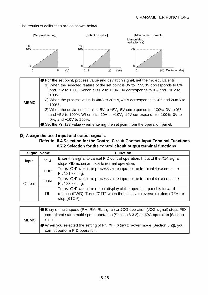
8 PARAMETER FUNCTIONS
8-48
The results of calibration are as shown below.
100
0
0 5 (V)
(%)100
0
0 20 (mA)
(%)
4
60
0
0 100 Deviation (%)
[Set point setting] [Detection value] [Manipulated variable]
variable (Hz)Manipulated
MEMO
For the set point, process value and deviation signal, set their % equivalents.1) When the selected feature of the set point is 0V to +5V, 0V corresponds to 0%
and +5V to 100%. When it is 0V to +10V, 0V corresponds to 0% and +10V to100%.
2) When the process value is 4mA to 20mA, 4mA corresponds to 0% and 20mA to100%.
3) When the deviation signal is -5V to +5V, -5V corresponds to -100%, 0V to 0%,and +5V to 100%. When it is -10V to +10V, -10V corresponds to -100%, 0V to0%, and +10V to 100%.
Set the Pr. 133 value when entering the set point from the operation panel.
(3) Assign the used input and output signals.Refer to: 8.4 Selection for the Control Circuit Contact Input Terminal Functions
8.7.2 Selection for the control circuit output terminal functions
Signal Name Function
Input X14Enter this signal to cancel PID control operation. Input of the X14 signalstops PID action and starts normal operation.
FUPTurns "ON" when the process value input to the terminal 4 exceeds thePr. 131 setting.
FDNTurns "ON" when the process value input to the terminal 4 exceeds thePr. 132 setting.Output
RLTurns "ON" when the output display of the operation panel is forwardrotation (FWD). Turns "OFF" when the display is reverse rotation (REV) orstop (STOP).
MEMO
Entry of multi-speed (RH, RM, RL signal) or JOG operation (JOG signal) stops PIDcontrol and starts multi-speed operation [Section 8.3.2] or JOG operation [Section8.6.1].
When you selected the setting of Pr. 79 = 6 (switch-over mode [Section 8.2]), youcannot perform PID operation.

8 PARAMETER FUNCTIONS
8-49
8
(4) Wiring example (when set point and process value are entered to perform PID operation)
NFBRST
STF
STR
RT(X14)
SD
10
2
5
4
UVW
FU(FUP)OL(FDN)
SE
M P
(OUT) (24V)
IPF(RL)
(COM)1
Drive UnitMotor
Power
supply
Power supply
(Process value) 4 to 20mA
Forward rotation
Reverse rotation
PID control operationcancel
Set point setting
Pump
Upper limit
Lower limitForward rotation
Reverse rotation
Output signal common
Detector type
output
output
typeFor 2-wire For 3-wire
- + + +-
MEMO
Makesure the detector power supply matches the specifications of the detectorused.
When the Pr. 128 value is set to choose PID action, the terminal 4 is made validautomatically. You need not turn "ON" the contact input terminal where the AUsignal has been assigned.
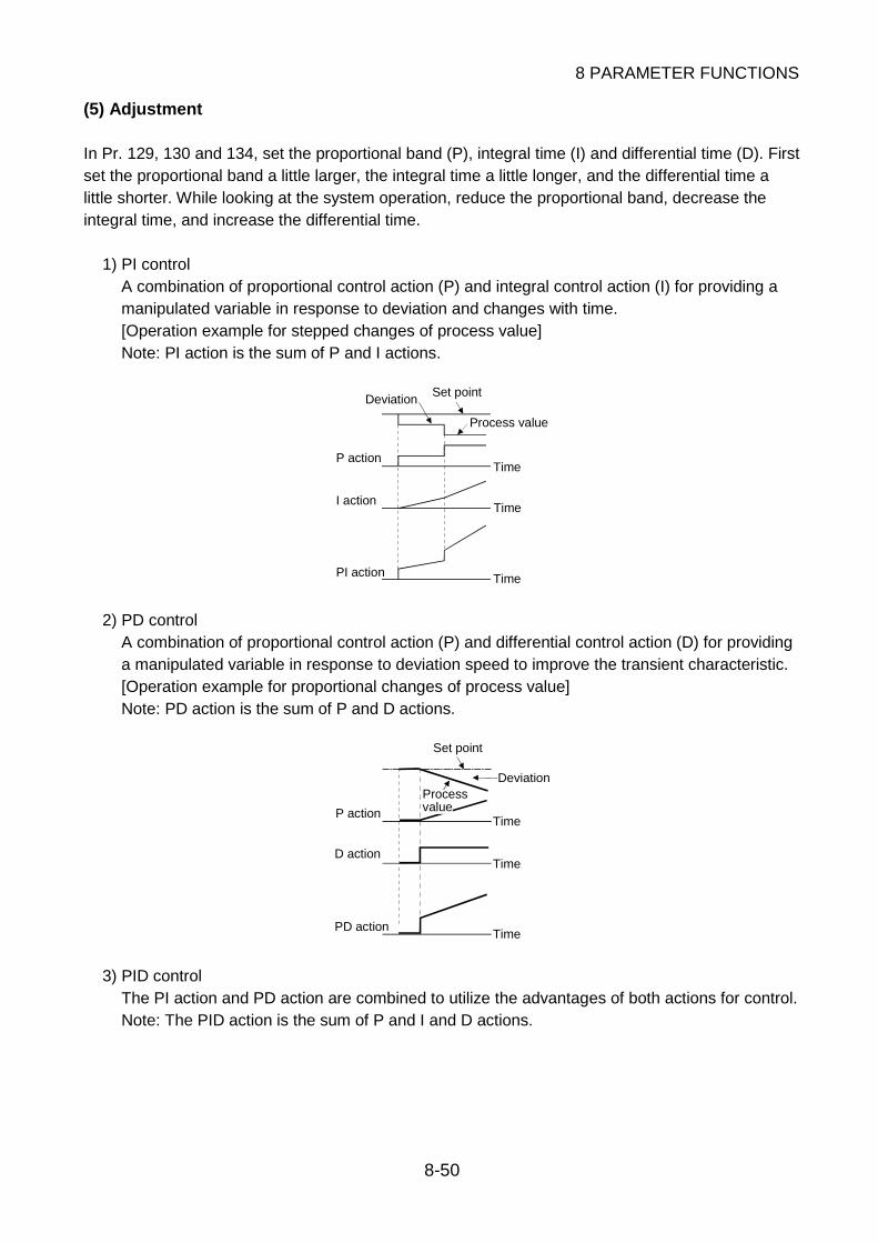
8 PARAMETER FUNCTIONS
8-50
(5) Adjustment
In Pr. 129, 130 and 134, set the proportional band (P), integral time (I) and differential time (D). Firstset the proportional band a little larger, the integral time a little longer, and the differential time alittle shorter. While looking at the system operation, reduce the proportional band, decrease theintegral time, and increase the differential time.
1) PI controlA combination of proportional control action (P) and integral control action (I) for providing amanipulated variable in response to deviation and changes with time.[Operation example for stepped changes of process value]Note: PI action is the sum of P and I actions.
Time
Time
Time
Process value
P action
I action
PI action
DeviationSet point
2) PD controlA combination of proportional control action (P) and differential control action (D) for providinga manipulated variable in response to deviation speed to improve the transient characteristic.[Operation example for proportional changes of process value]Note: PD action is the sum of P and D actions.
Time
Time
Time
Deviation
PD action
P action
D action
Set point
Processvalue
3) PID controlThe PI action and PD action are combined to utilize the advantages of both actions for control.Note: The PID action is the sum of P and I and D actions.

8 PARAMETER FUNCTIONS
8-51
8
(6) Setting example
A detector which outputs the process values of 4mA at 0°C and 20mA at 50°C is used to adjust thetemperature to 25°C under PID control.
Procedure Description
Determinethe set point.
Determine the set point ofthe item to be adjusted.
Set Pr. 128.
Convert theset point into
%.
Calculate the ratio of theset point to the detectoroutput.
When the detector used has the specifications that 0°Cis equivalent to 4mA and 50°C to 20mA, the set point25°C is 50% because 4mA is equivalent to 0% and20mA to 100%.
Calibrate thesignals.
Calibrate the set pointinput and detector outputas required.
Make calibration using Pr. 902 to 905 [Section 8.3.1].
Set the setpoint.
Enter a voltage intoterminal 2 according tothe set point (%).
When the selected feature of the terminal 2 is 0 to 5V, 0Vcorresponds to 0% and 5V to 100%. Therefore, enter2.5V which corresponds to 50%. When entering the setpoint from the operation panel, set "50" in Pr. 133.
OperationTurn "ON" the start signaland check that theprocess value is stable.
Set the proportional band, Pr. 129, slightly larger, theintegral time, Pr. 130, slightly longer, and the differentialtime, Pr. 134, slightly shorter, and start operation.
AdjustmentStabilize the operatingstatus (detector output).
When stableReduce the proportional band, decrease the integraltime, and increase the differential time to increasethe response performance. When instableIncrease the proportional band, increase the integraltime, and decrease the differential time.

8 PARAMETER FUNCTIONS
8-52
8.6.4 Alarm retry operation
Initial value
Pr. 65 "retry item selection" 3
A retry is a function to automatically reset an alarm and restart operation if an alarm is detected andoperation stopped. The following table gives the alarms which enable a retry. By changing the setvalue, you can select the alarm group which is reset for a retry. indicates the alarms to be resetfor a retry.
SettingAlarm Displayed on Operation Panel(Actual Characters) 0 1 2 3 4 5
(E. 0C1)
(E. 0C2)
(E. 0C3)
(E. 0V1 to E. 0V3)
(E. THM)
(E. THT)
(E. IPF)
(E. UVT)
(E. GF)
(E. OHT)
(E. OLT)
Refer to: Chapter 6, 6.1.1 Protective function activated
Initial value
Pr. 67 "retry count selection" 0
Select the number of retries to be executed.
Setting Range Retry Count Alarm Signal Output during Retry Period
0 No retry function 1 to 10 1 to 10 times Not output
101 to 110 1 to 10 times Output
If operation cannot be resumed within the preset number of retries, "E. RET" appears on theoperation panel, the alarm signal is output, and operation is stopped.
Refer to: Chapter 6, 6.1.1 Protective function activated

8 PARAMETER FUNCTIONS
8-53
8
Initial value
Pr. 68 "retry time selection" 1
Setting Range Unit Function
0.0 to 10.0 s Select the waiting time from an alarm occurrence stop to a retry start.
When the motor is restarted by a retry during coasting, the overcurrent alarm may be activated. SetPr. 68 so that a retry is made after the motor has stopped.
Initial value
Pr. 69 "retry count display" 0
When a period five times longer than the value set in Pr. 68 has elapsed after operation is restartedby a retry, Pr. 69 shows the cumulative number of successful retries. Write "0" to clear thecumulative count.
Pr. 68 Pr. 68 4 Pr. 68 Pr. 68 Pr. 68t1 t2 t3 Time
t1, t2, t3, <Pr. 68 4
Ru
nnin
g s
pee
d Alarm
occurrence
Coasting to stop
Alarm
occurrence
Alarm
occurrence
Alarm
occurrence
Alarm
occurrence
Pr. 69 is incremented and
Pr. 67 is reset.
Retry operation successful
(E. RET) appears, alarm signal is
output, and operation is stopped.
Retry count excess (when Pr. 67=3)
Refer to: Chapter 6, 6.1.1 Protective function activated
MEMO
If alarms occur consecutively within a period five times longer than the time set inPr. 68, the operation panel may display an alarm which is different from the latestalarm code. When a retry is made, only the alarm code which occurred the first timeis stored.
When an alarm is reset at a retry made by the retry function, the accumulated dataof the electronic overcurrent protection and others are not cleared.
CAUTION When you have set the retry function, stay away from the motor and machine. Themotor will start suddenly while it is at an alarm occurrence stop.

8 PARAMETER FUNCTIONS
8-54
8.6.5 Power failure deceleration-to-stop operationInitial value
Pr. 261 "power failure stop selection" 0Pr. 262 "subtracted speed at deceleration start" 0Pr. 263 "subtraction starting speed" 2000Pr. 264 "power-failure deceleration time 1" 5Pr. 265 "power-failure deceleration time 2" 9999Pr. 266 "power-failure deceleration time switch-over speed" 2000
If input power is switched "OFF" due to a power failure, regenerative energy from the motor can beutilized to decelerate the motor to a stop.Remove the jumpers across the main circuit terminals R-R1 and S-S1, and connect R1-P/+ and S1-N/-.
Power supply
Spe
ed
Pr. 266Switch-over
speed
SubtractedPr. 262
speed
Power-failure deceleration time 1Pr. 264 Power-failure
deceleration time 2
Pr. 265
Pr. Setting Range Unit Operation0 Switching "OFF" input power coasts the motor to a stop.
2611 Switching "OFF" input power decelerates the motor to a
stop
262 0 to 600 r/minNormally, operation can be performed with the factorysetting unchanged. Adjust the speed to meet the loadspecifications (inertia moment, torque magnitude).
0 to 3000 r/min
When the motor speed at power "OFF" is greater than thevalue set in Pr. 263, deceleration starts at the value foundby subtracting the Pr. 262 setting from the motor speed.When the motor speed is less than the Pr. 263 setting,the motor is decelerated to a stop, starting at the motorspeed. When the Pr. 263 setting and motor speed areclose, the Pr. 262 function may not be activated.
263
9999 Deceleration starts at the value found by subtracting thePr. 262 setting from the motor speed at power "OFF".
Pr. 21 = 0 0.0 to 3600264
Pr. 21 = 1 0.00 to 360s
Set a deceleration slope down to the Pr. 266 setting. Setthe slope in terms of the deceleration time, Pr. 264, fromthe speed set in Pr. 20 [Section 8.5.2] to a stop. Thesetting range can be changed using Pr. 21 [Section 8.5.2].
Pr. 21 = 0 0.0 to 3600
Pr. 21 = 1 0.00 to 360s
Set a deceleration slope down to the Pr. 266 setting. Setthe slope in terms of the deceleration time, Pr. 264, fromthe speed set in Pr. 20 [Section 8.5.2] to a stop. Thesetting range can be changed using Pr. 21 [Section 8.5.2].265
9999 The deceleration slope from the Pr. 266 setting to astop is the value set in Pr. 264.
266 0 to 3000 r/min Set the speed at which the deceleration slope ischanged.
MEMO
Depending on the load, the power-failure detection function may not be activatedproperly, causing the motor to coast to a stop. If the motor speed at power "OFF" is less than the Pr. 262 setting, the motor stopsimmediately. If power is switched on during power-failure deceleration operation, deceleration-to-stop operation is continued. To restart, turn "OFF" the start signal once, then turn it"ON" again. When the FR-HC high power factor converter is used, this function is made invalid.

8 PARAMETER FUNCTIONS
8-55
8
8.7 Monitoring of Operation Status
8.7.1 Selection of operation panel display data
Initial value
Pr. 37 "speed unit switch-over 1" 0
Change the display unit of the operation panel or FR-PU04 parameter unit (option).
Setting Range Function
0 The motor speed is displayed. The unit is r/min.
1 to 9998
By setting a value corresponding to the rated speed, a machine operationamount equivalent can be displayed. At the setting of "10", 10 appearswhen the motor reaches the rated speed and "3" appears when the motorreaches 1/3 of the rated speed.
MEMO
Since the operation panel display has 4 digits, "- - - -" appears when the monitorvalue is "10000" or greater. To display a value of "10000" or greater, use theoptional FR-PU04 parameter unit.
Changing the speed unit switch-over setting also changes the units of the otherspeed-related parameter settings.
Initial value
Pr. 144 "speed unit switch-over 2" 0
Set this parameter to show the display unit of the operation panel or FR-PU04 parameter unit(option) as an output frequency.
Setting Range Function
0 The Pr. 37 setting is enabled.
1The Pr. 37 setting is disabled and the output frequency is displayed. Theunit is Hz.
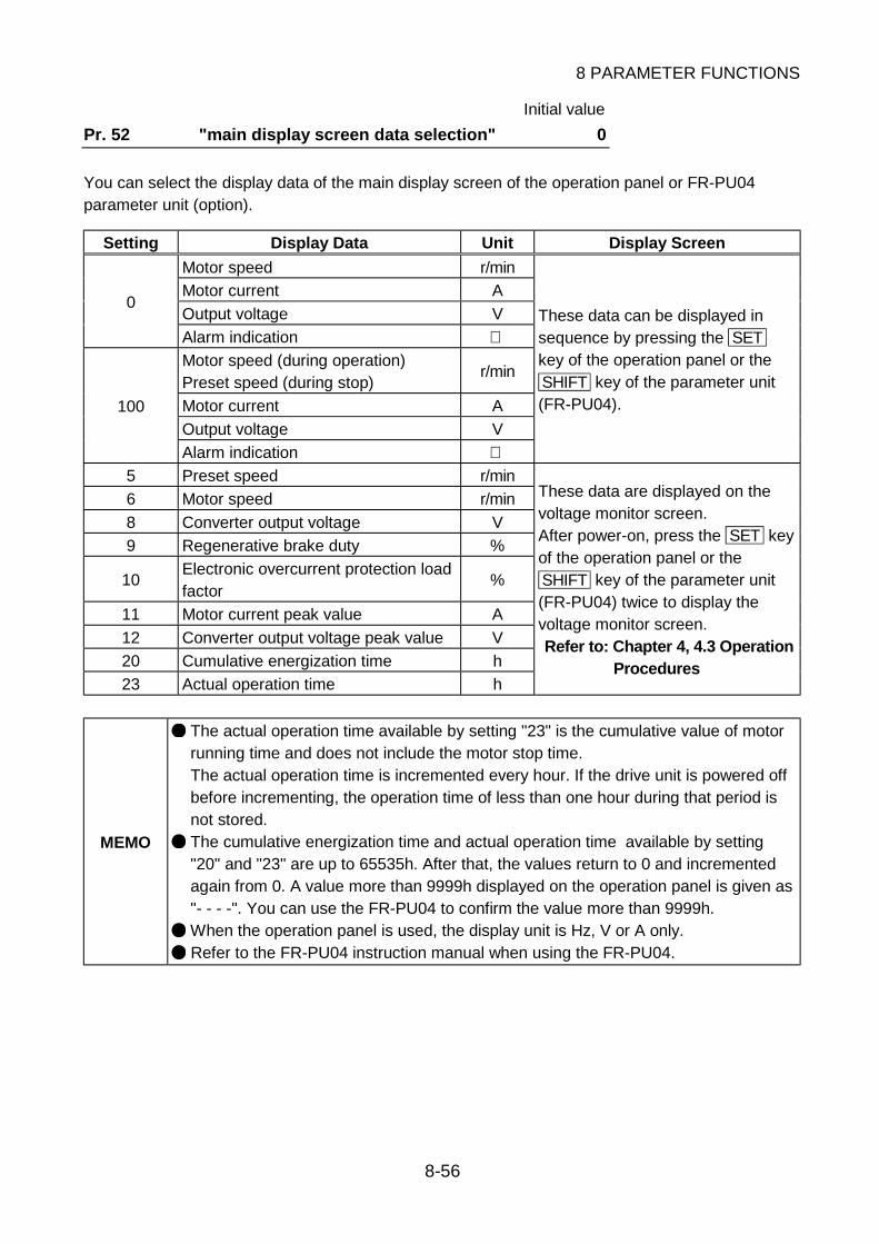
8 PARAMETER FUNCTIONS
8-56
Initial value
Pr. 52 "main display screen data selection" 0
You can select the display data of the main display screen of the operation panel or FR-PU04parameter unit (option).
Setting Display Data Unit Display Screen
Motor speed r/min
Motor current A
Output voltage V0
Alarm indication Motor speed (during operation)Preset speed (during stop)
r/min
Motor current A
Output voltage V
100
Alarm indication
These data can be displayed insequence by pressing the SETkey of the operation panel or theSHIFT key of the parameter unit(FR-PU04).
5 Preset speed r/min
6 Motor speed r/min
8 Converter output voltage V
9 Regenerative brake duty %
10Electronic overcurrent protection loadfactor
%
11 Motor current peak value A
12 Converter output voltage peak value V
20 Cumulative energization time h
23 Actual operation time h
These data are displayed on thevoltage monitor screen.After power-on, press the SET keyof the operation panel or theSHIFT key of the parameter unit(FR-PU04) twice to display thevoltage monitor screen.Refer to: Chapter 4, 4.3 Operation
Procedures
MEMO
The actual operation time available by setting "23" is the cumulative value of motorrunning time and does not include the motor stop time.The actual operation time is incremented every hour. If the drive unit is powered offbefore incrementing, the operation time of less than one hour during that period isnot stored.
The cumulative energization time and actual operation time available by setting"20" and "23" are up to 65535h. After that, the values return to 0 and incrementedagain from 0. A value more than 9999h displayed on the operation panel is given as"- - - -". You can use the FR-PU04 to confirm the value more than 9999h.
When the operation panel is used, the display unit is Hz, V or A only.
Refer to the FR-PU04 instruction manual when using the FR-PU04.

8 PARAMETER FUNCTIONS
8-57
8
Initial value
Pr. 171 "actual operation hour meter clear" 0
You can clear the actual operation time read by setting "23" in Pr. 52.Write "0" in Pr. 171. (The parameter is factory set to "0")
MEMO You cannot clear the cumulative energization time read by setting 20 in Pr. 52.
Initial value
Pr. 53 "level display data selection" 1
This parameter is designed for use with the FR-PU04 parameter unit (option) only. Select the datato be displayed on the level meter of the FR-PU04.
Setting Display Data Unit Full-Scale
0 No indication 1 Motor speed r/min Value set in Pr. 55 [Section 8.7.5]
2 Motor current A Value set in Pr. 56 [Section 8.7.5]
3 Output voltage V 400V
5 Preset speed r/min Value set in Pr. 55 [Section 8.7.5]
8 Converter output voltage V 400V
9 Regenerative brake duty % Value set in Pr. 70 [Section 8.7.5]
10Electronic overcurrent protection loadfactor
% Thermal relay operation level
11 Motor current peak value A Value set in Pr. 56 [Section 8.7.5]
12 Converter output voltage peak value V 400V
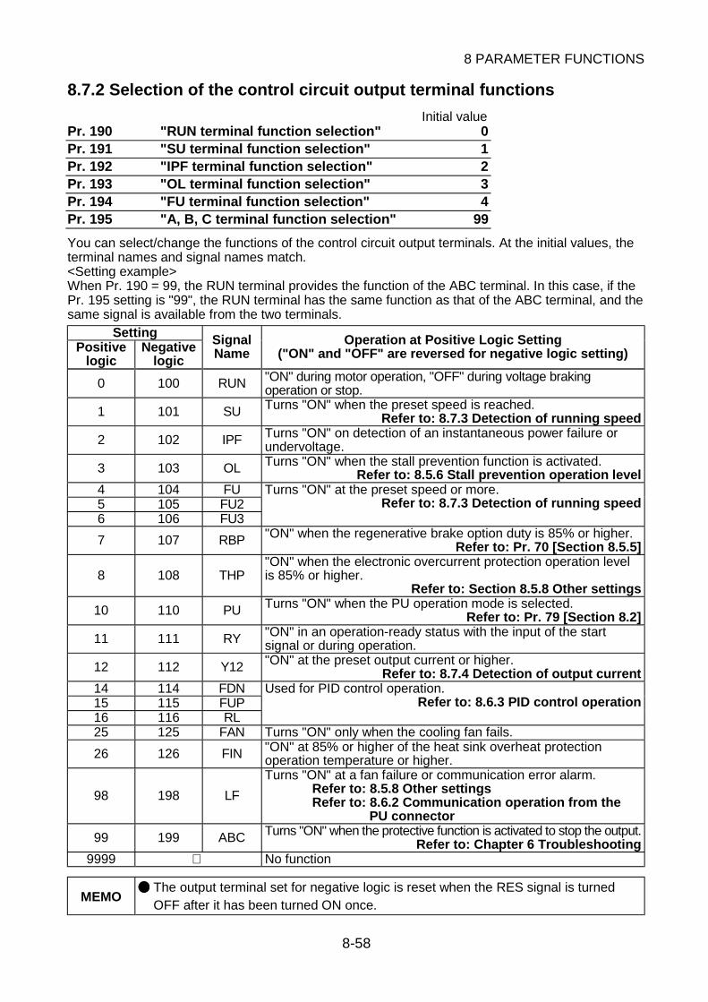
8 PARAMETER FUNCTIONS
8-58
8.7.2 Selection of the control circuit output terminal functions
Initial valuePr. 190 "RUN terminal function selection" 0Pr. 191 "SU terminal function selection" 1Pr. 192 "IPF terminal function selection" 2Pr. 193 "OL terminal function selection" 3Pr. 194 "FU terminal function selection" 4Pr. 195 "A, B, C terminal function selection" 99
You can select/change the functions of the control circuit output terminals. At the initial values, theterminal names and signal names match.<Setting example>When Pr. 190 = 99, the RUN terminal provides the function of the ABC terminal. In this case, if thePr. 195 setting is "99", the RUN terminal has the same function as that of the ABC terminal, and thesame signal is available from the two terminals.
SettingPositive
logicNegative
logic
SignalName
Operation at Positive Logic Setting("ON" and "OFF" are reversed for negative logic setting)
0 100 RUN "ON" during motor operation, "OFF" during voltage brakingoperation or stop.
1 101 SU Turns "ON" when the preset speed is reached.Refer to: 8.7.3 Detection of running speed
2 102 IPF Turns "ON" on detection of an instantaneous power failure orundervoltage.
3 103 OL Turns "ON" when the stall prevention function is activated.Refer to: 8.5.6 Stall prevention operation level
4 104 FU5 105 FU26 106 FU3
Turns "ON" at the preset speed or more.Refer to: 8.7.3 Detection of running speed
7 107 RBP "ON" when the regenerative brake option duty is 85% or higher.Refer to: Pr. 70 [Section 8.5.5]
8 108 THP"ON" when the electronic overcurrent protection operation levelis 85% or higher.
Refer to: Section 8.5.8 Other settings
10 110 PU Turns "ON" when the PU operation mode is selected.Refer to: Pr. 79 [Section 8.2]
11 111 RY "ON" in an operation-ready status with the input of the startsignal or during operation.
12 112 Y12 "ON" at the preset output current or higher.Refer to: 8.7.4 Detection of output current
14 114 FDN15 115 FUP16 116 RL
Used for PID control operation.Refer to: 8.6.3 PID control operation
25 125 FAN Turns "ON" only when the cooling fan fails.
26 126 FIN "ON" at 85% or higher of the heat sink overheat protectionoperation temperature or higher.
98 198 LF
Turns "ON" at a fan failure or communication error alarm.Refer to: 8.5.8 Other settingsRefer to: 8.6.2 Communication operation from the
PU connector
99 199 ABC Turns "ON" when the protective function is activated to stop the output.Refer to: Chapter 6 Troubleshooting
9999 No function
MEMO The output terminal set for negative logic is reset when the RES signal is turnedOFF after it has been turned ON once.

8 PARAMETER FUNCTIONS
8-59
8
Initial value
Pr. 157 "OL signal output timer" 0
You can set the output timing of the OL signal.
Setting Range Unit Function0 s Output as soon as the stall prevention operation level is reached.
0.1 to 25.0 sOutput the preset period of time after the stall preventionoperation level has been reached.
Refer to: 8.5.6 Stall prevention operation level
Pr. 157
OL signal
Overload status (OL operation)
Initial value
Pr. 76 "alarm code output selection" 0
You can output the detected alarm code as a 4-bit digital signal from the control circuit transistoroutput terminals. The alarm code can be read using an external controller to display its remedy onthe display.
Setting Function0 Alarm code is not output.1 Alarm code output-only terminal.
2The alarm code is output only at detection of the alarm. During normal operation,the function is the same as in "0" setting.
Alarm code output timing
200ms
Alarm code
ABC signal
Alarm code signal

8 PARAMETER FUNCTIONS
8-60
The operations of the control circuit transistor output terminals relative to the alarm codes are listedin the following table.
Logic of OutputTerminals
Alarm Code Displayed on Operation Panel(Actual Characters)
SU IPF OL FU
Definition ofLogic
(E. 0C1) 0 0 0 1
(E. 0C2) 0 0 1 0
(E. 0C3) 0 0 1 1
(E. 0V1 to E. 0V3) 0 1 0 0
(E. THM) 0 1 0 1
(E. THT) 0 1 1 0
(E. IPF) 0 1 1 1
(E. UVT) 1 0 0 0
(E. FIN) 1 0 0 1
(E. BE) 1 0 1 0
(E. GF) 1 0 1 1
(E. OHT) 1 1 0 0
(E. OLT) 1 1 0 1
(E. OPT) 1 1 1 0
(E. PE)
(E. PUE)
(E. RET)
(E. LF)
(E. CPU)
(E. 6, E. 7)
1 1 1 1
Logic "0" indicatesthat the transistoroutput terminal is"OFF", and logic"1" indicates thatthe transistoroutput terminal is"ON".
MEMO
Refer to "Chapter 6 Troubleshooting" for details of the alarm codes.
When this function is activated, Pr. 191 to 194 are disabled.
This function is activated for the terminals SU, IPF, OL and FU only. It cannot beactivated for the other terminals where the SU, IPF, OL and FU signals have beenselected.
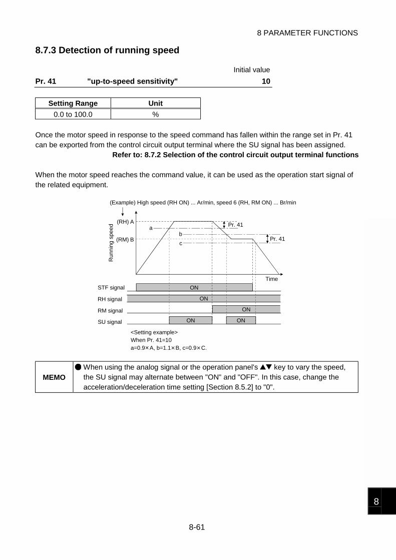
8 PARAMETER FUNCTIONS
8-61
8
8.7.3 Detection of running speed
Initial value
Pr. 41 "up-to-speed sensitivity" 10
Setting Range Unit
0.0 to 100.0 %
Once the motor speed in response to the speed command has fallen within the range set in Pr. 41can be exported from the control circuit output terminal where the SU signal has been assigned.
Refer to: 8.7.2 Selection of the control circuit output terminal functions
When the motor speed reaches the command value, it can be used as the operation start signal ofthe related equipment.
A
B
ab
c
Pr. 41
Pr. 41
ON ON
(RM)
(RH)
ON
ON
ON
<Setting example>When Pr. 41=10a=0.9 A, b=1.1 B, c=0.9 C.
(Example) High speed (RH ON) ... Ar/min, speed 6 (RH, RM ON) ... Br/min
Run
nin
g s
pee
d
STF signal
RH signal
RM signal
SU signal
Time
MEMO
When using the analog signal or the operation panel's key to vary the speed,the SU signal may alternate between "ON" and "OFF". In this case, change theacceleration/deceleration time setting [Section 8.5.2] to "0".
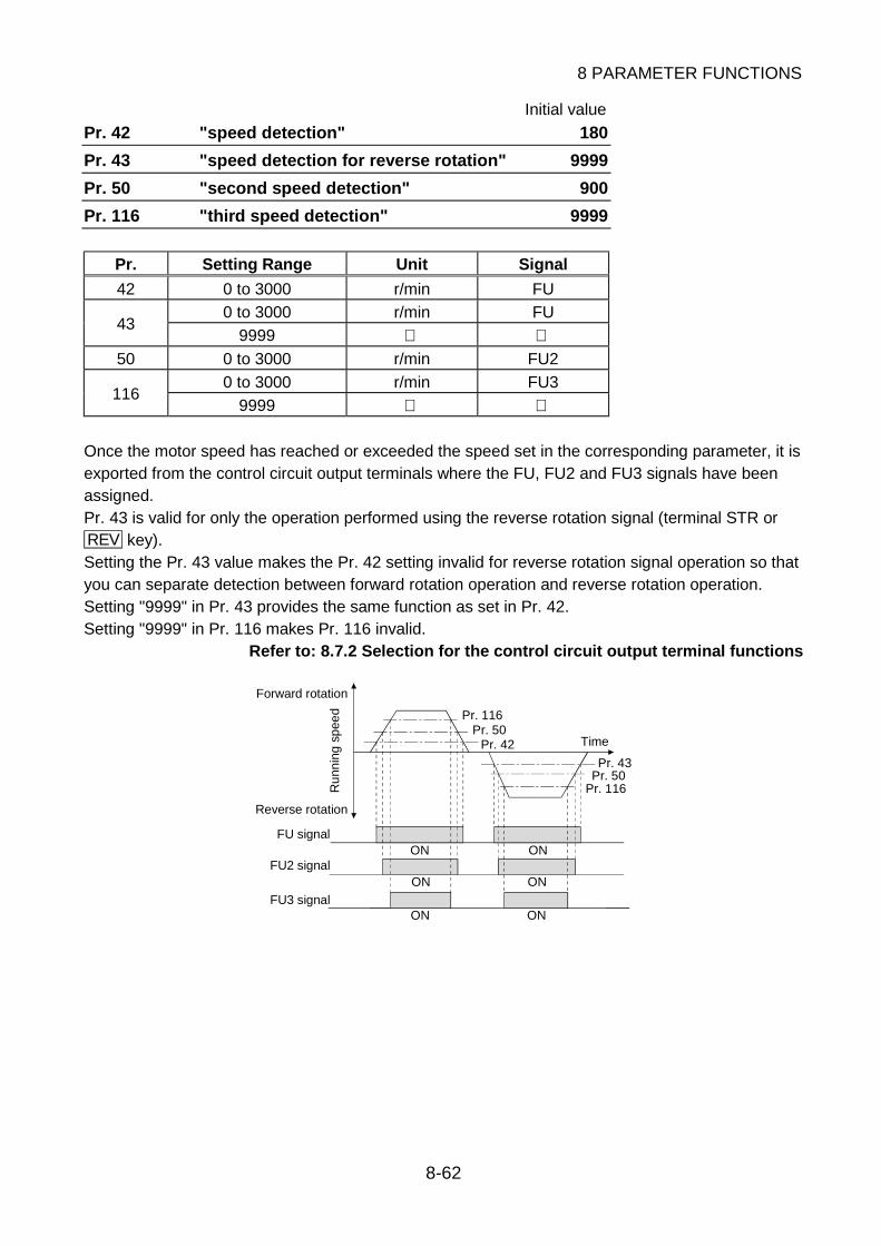
8 PARAMETER FUNCTIONS
8-62
Initial value
Pr. 42 "speed detection" 180
Pr. 43 "speed detection for reverse rotation" 9999
Pr. 50 "second speed detection" 900
Pr. 116 "third speed detection" 9999
Pr. Setting Range Unit Signal
42 0 to 3000 r/min FU
0 to 3000 r/min FU43
9999 50 0 to 3000 r/min FU2
0 to 3000 r/min FU3116
9999
Once the motor speed has reached or exceeded the speed set in the corresponding parameter, it isexported from the control circuit output terminals where the FU, FU2 and FU3 signals have beenassigned.Pr. 43 is valid for only the operation performed using the reverse rotation signal (terminal STR orREV key).Setting the Pr. 43 value makes the Pr. 42 setting invalid for reverse rotation signal operation so thatyou can separate detection between forward rotation operation and reverse rotation operation.Setting "9999" in Pr. 43 provides the same function as set in Pr. 42.Setting "9999" in Pr. 116 makes Pr. 116 invalid.
Refer to: 8.7.2 Selection for the control circuit output terminal functions
Pr. 116Pr. 50
Pr. 42
Pr. 43Pr. 50
Pr. 116
ON
ON
ON
ON
ON
ON
Time
Forward rotation
Ru
nnin
g s
pee
d
Reverse rotation
FU signal
FU2 signal
FU3 signal

8 PARAMETER FUNCTIONS
8-63
8
8.7.4 Detection of output current
Initial value
Pr. 150 "output current detection level" 150
Pr. 151 "output current detection time" 0
Pr. Setting Range Unit
150 0.0 to 200.0 %
151 0.0 to 10.0 s
If the motor current remains higher than the Pr. 150 setting for longer than the time set in Pr. 151,the terminal where the assigned Y12 signal turns "ON". The Pr. 150 value is based on the ratedmotor current.Use any of Pr. 190 to Pr. 195 [Section 8.7.2] to assign the terminal used for Y12 signal output.Once turned on, the Y12 signal remains on for at least 100ms.
Pr. 151
Pr. 150
ON OFF
Time
At least 100ms
Y12 signal
Output current
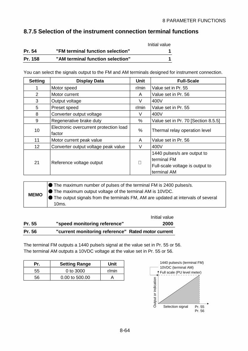
8 PARAMETER FUNCTIONS
8-64
8.7.5 Selection of the instrument connection terminal functions
Initial value
Pr. 54 "FM terminal function selection" 1
Pr. 158 "AM terminal function selection" 1
You can select the signals output to the FM and AM terminals designed for instrument connection.
Setting Display Data Unit Full-Scale
1 Motor speed r/min Value set in Pr. 55
2 Motor current A Value set in Pr. 56
3 Output voltage V 400V
5 Preset speed r/min Value set in Pr. 55
8 Converter output voltage V 400V
9 Regenerative brake duty % Value set in Pr. 70 [Section 8.5.5]
10Electronic overcurrent protection loadfactor
% Thermal relay operation level
11 Motor current peak value A Value set in Pr. 56
12 Converter output voltage peak value V 400V
21 Reference voltage output
1440 pulses/s are output toterminal FMFull-scale voltage is output toterminal AM
MEMO
The maximum number of pulses of the terminal FM is 2400 pulses/s.
The maximum output voltage of the terminal AM is 10VDC.
The output signals from the terminals FM, AM are updated at intervals of several10ms.
Initial value
Pr. 55 "speed monitoring reference" 2000
Pr. 56 "current monitoring reference" Rated motor current
The terminal FM outputs a 1440 pulse/s signal at the value set in Pr. 55 or 56.The terminal AM outputs a 10VDC voltage at the value set in Pr. 55 or 56.
Pr. Setting Range Unit
55 0 to 3000 r/min
56 0.00 to 500.00 A
Pr. 55Pr. 56
Selection signal
1440 pulses/s (terminal FM)10VDC (terminal AM)Full scale (PU level meter)
Out
put o
r in
dica
tion

8 PARAMETER FUNCTIONS
8-65
8
Pr. 900 "FM terminal calibration"
Using the operation panel or parameter unit, you can calibrate the full scale of a meter connected tothe FM instrument connection terminal.The terminal FM outputs a 1mADC current at the value set in Pr. 55 or 56. When the full scale ofthe meter used must be calibrated, it can be adjusted using Pr. 900.
<Calibration example>Connect a 1mADC ammeter having a full-scale graduation"25" and adjust it to deflect to the graduation "20" at therunning speed 2000r/min.
1mADC ammeter
020
25
<Calibration procedure using operation panel>1) Make sure that "2000" has been set in Pr. 55.2) Confirm that the (+) terminal of the meter is connected to terminal FM and the (-) terminal to
terminal SD.3) When a calibration resistor is connected on the meter side, adjust it until the resistance value
is "0" or remove it.4) Set the operation mode to the PU operation mode.5) Set the running speed to 2000r/min.6) Press the SET key.7) Read Pr. 900.8) Press the FWD or REV key to start operation. You need not connect the motor.9) Using the key, make adjustment until the meter deflects to the graduation "20". Holding
down the key decreases the current flowing in the ammeter. The key increases thecurrent.
10) Press the SET key until Pr. 900 flickers. (About 2s)11) Press the STOP/RESET key to stop operation.
MEMO
Holding down the key increases the current to about 2mA. Check the maximumrating of the ammeter and make adjustment.
You can also calibrate the meter for external operation. Set the frequency in theexternal operation mode and make calibration in accordance with steps 7) to 11).
You can also make calibration during operation.
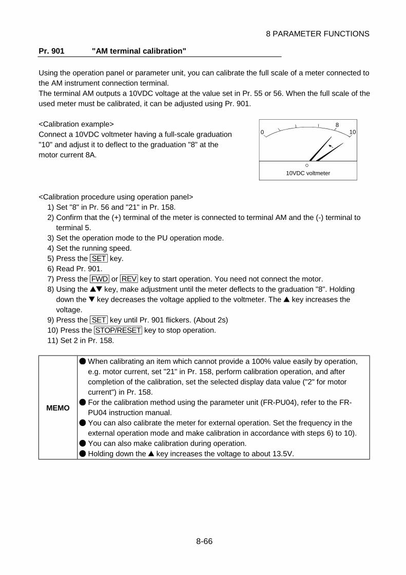
8 PARAMETER FUNCTIONS
8-66
Pr. 901 "AM terminal calibration"
Using the operation panel or parameter unit, you can calibrate the full scale of a meter connected tothe AM instrument connection terminal.The terminal AM outputs a 10VDC voltage at the value set in Pr. 55 or 56. When the full scale of theused meter must be calibrated, it can be adjusted using Pr. 901.
<Calibration example>Connect a 10VDC voltmeter having a full-scale graduation"10" and adjust it to deflect to the graduation "8" at themotor current 8A.
10VDC voltmeter
08
10
<Calibration procedure using operation panel>1) Set "8" in Pr. 56 and "21" in Pr. 158.2) Confirm that the (+) terminal of the meter is connected to terminal AM and the (-) terminal to
terminal 5.3) Set the operation mode to the PU operation mode.4) Set the running speed.5) Press the SET key.6) Read Pr. 901.7) Press the FWD or REV key to start operation. You need not connect the motor.8) Using the key, make adjustment until the meter deflects to the graduation "8". Holding
down the key decreases the voltage applied to the voltmeter. The key increases thevoltage.
9) Press the SET key until Pr. 901 flickers. (About 2s)10) Press the STOP/RESET key to stop operation.11) Set 2 in Pr. 158.
MEMO
When calibrating an item which cannot provide a 100% value easily by operation,e.g. motor current, set "21" in Pr. 158, perform calibration operation, and aftercompletion of the calibration, set the selected display data value ("2" for motorcurrent") in Pr. 158.
For the calibration method using the parameter unit (FR-PU04), refer to the FR-PU04 instruction manual.
You can also calibrate the meter for external operation. Set the frequency in theexternal operation mode and make calibration in accordance with steps 6) to 10).
You can also make calibration during operation.
Holding down the key increases the voltage to about 13.5V.

8 PARAMETER FUNCTIONS
8-67
8
8.8 Control Parameters
Do not change the settings of these parameters since they have been factory-set to the optimumvalues.When changing their settings, you need to set 801 in Pr. 77.
<Control parameters>
Initial value
Pr. 733 "motor protection electronic overcurrent protection value" 100
Pr. Setting Range Unit Operation
733 0.0 to 200.0 %You can change the operation reference torque of motor overheatprotection.
CAUTIONDo not use Pr. 733 at more than the initial value 100.If you use it by force-cooling the motor, consult the factory before using it.
Initial value
Pr. 728 "low speed region acceleration time" 5
Pr. Setting Range Unit Operation
728 0.00 to 15.00 sThe maximum value of acceleration time in less than the speedcontrol range (less than 100r/min) is specified. The referencespeed for acceleration time is the rated speed 2000r/min.
CAUTIONDo not use Pr. 728 at more than the initial value 5.Doing so may not provide the starting torque 150%.
Initial value
Pr. 713 "speed response time" 10
Pr. 714 "speed response adjustment" 100
Pr. Setting Range Unit Operation
713 2 to 30 714 20.0 to 300.0 %
Both parameters can make speed response faster as the settingis increased.
CAUTIONIncreasing the Pr. 713 and Pr. 714 values can make speed response faster, but use them attheir initial values since vibration may occur depending on the load conditions.If vibration has occurred, decrease the Pr. 714 value.

8 PARAMETER FUNCTIONS
8-68
Initial value
Pr. 71 "applied motor" 1
Pr. Setting Range Unit Operation
71 1 Set the motor to be used.
Initial value
Pr. 80 "motor capacity"
Pr. Setting Range Unit Operation
800.5, 1.0, 1.5,
2.0, 3.5kW
Set the motor capacity.Set the same capacity as that of the drive unit.
Note: Changing the Pr. 71 or Pr. 80 changes the motor-specific control constants used in the driveunit. Note that after changing the value, you need to make a reset.
Initial value
Pr. 736 "overspeed adjustment factor" 100
Pr. Setting Range Unit Operation
736 0 to 100 Adjust overspeed (overshoot, undershoot).
The overspeed value depends on the load inertia, acceleration/deceleration time and load torque(friction torque).Using the acceleration torque (proportional to load inertia/acceleration/deceleration time) and loadtorque (friction torque) to adjust the overspeed adjustment factor as outlined below allowsoverspeed to be suppressed effectively.
Overspeed AdjustmentFactor
0 to 100
Load torqueSmaller
Larger
Acceleration torqueSmaller
Larger
Initial value
Pr. 737 "maximum voltage braking ending time (s)" 3
Pr. Setting Range Unit Operation
737 0.0 to 60.0 s
Set the maximum voltage braking ending time when 9999 is set inPr. 11 [Section 8.5.4] "voltage braking operation time".Normally, the motor stops running within about 3s. When it isrotated by external force, however, use this parameter to endvoltage braking forcibly.
Initial value
Pr. 738 "stop time for operation reversion (s)" 0
Pr. Setting Range Unit Operation
738 0.0 to 60.0 sSet the stop time for switch-over from forward rotation to reverserotation or from reverse rotation to forward rotation. If you set 0,there will be a stop time of at least about 100ms.

8 PARAMETER FUNCTIONS
8-69
8
APPENDIX 1 PARAMETER LIST (NUMERICAL ORDER)
InstructionCode
DataNo. Name Setting Range
InitialValue
CustomerSetting
read Write Extension
Referto
1 Maximum speed 0 to 3000r/min 3000 01 81 02 Minimum speed 0 to 3000r/min 0 02 82 0
8-24
4Three-speed setting(high speed)
0 to 3000r/min 2000 04 84 0
5Three-speed setting(middle speed)
0 to 3000r/min 1000 05 85 0
6Three-speed setting(low speed)
0 to 3000r/min 500 06 86 0
8-18
7 Acceleration time0.0 to 3600s/0.00 to 360.0s
5 07 87 0
8 Deceleration time0.0 to 3600s/0.00 to 360.0s
5 08 88 08-26
9Electronic thermalO/L relay
0, 1 1 09 89 0 8-32
10Braking voltageoperation speed
40 to 200r/min 100 0A 8A 0
11Braking voltageoperation time
0.0 to 60.0s,9999
9999 0B 8B 08-29
13Minimum motorspeed
40 to 100r/min 100 0D 8D 0 8-24
15 JOG speed 100 to 3000r/min 200 0F 8F 0
16JOG acceleration/deceleration time
0.0 to 3600s/0.00 to 360.0s
0.5 10 90 08-34
17MRS inputselection
0, 2 0 11 91 0 8-21
20Acceleration/decelerationreference speed
1 to 3000r/min 2000 14 94 0
21Acceleration/deceleration timeunit
0, 1 0 15 95 0
8-26
22Stall preventionoperation level
0, 150% 150 16 96 0 8-31
24Multi-speed setting(speed 4)
0 to 3000r/min,9999
9999 18 98 0
25Multi-speed setting(speed 5)
0 to 3000r/min,9999
9999 19 99 0
26Multi-speed setting(speed 6)
0 to 3000r/min,9999
9999 1A 9A 0
27Multi-speed setting(speed 7)
0 to 3000r/min,9999
9999 1B 9B 0
8-18
PA
RA
ME
TE
R L
IST

8 PARAMETER FUNCTIONS
8-70
APPENDIX 1 PARAMETER LIST (NUMERICAL ORDER)
InstructionCode
DataNo. Name Setting Range
InitialValue
CustomerSetting
read Write Extension
Referto
28Contact inputspeedcompensation
0, 1 0 1C 9C 0 8-20
29Acceleration/decelerationpattern
0, 1, 2 0 1D 9D 0 8-28
30Regenerativebrake optionselection
0, 1, 2 0 1E 9E 0 8-30
31Speed commandjump 1A
0 to 3000r/min,9999
9999 1F 9F 0
32Speed commandjump 1B
0 to 3000r/min,9999
9999 20 A0 0
33Speed commandjump 2A
0 to 3000r/min,9999
9999 21 A1 0
34Speed commandjump 2B
0 to 3000r/min,9999
9999 22 A2 0
35Speed commandjump 3A
0 to 3000r/min,9999
9999 23 A3 0
36Speed commandjump 3B
0 to 3000r/min,9999
9999 24 A4 0
8-25
37Speed unit switch-over 1
0 to 9998 0 25 A5 0 8-55
41Up-to-speedsensitivity
0.0 to 100.0% 10 29 A9 0 8-61
42 Speed detection 0 to 3000r/min 180 2A AA 0
43Speed detectionfor reverse rotation
0 to 3000r/min,9999
9999 2B AB 08-62
44Secondacceleration time
0.0 to 3600s/0.00 to 360.0s, 9999
9999 2C AC 0
45Seconddeceleration time
0.0 to 3600s/0.00 to 360.0s, 9999
9999 2D AD 08-27
50Second speeddetection
0 to 3000r/min 900 32 B2 0 8-62
52Main display screendata selection
Refer to manualdescription.
0 34 B4 0 8-56
53Level display dataselection
Refer to manualdescription.
1 35 B5 0 8-57
54FM terminalfunction selection
Refer to manualdescription.
1 36 B6 0
55Speed monitoringreference
0 to 3000r/min 2000 37 B7 0
56Current monitoringreference
0.00 to 500.00ARatedmotorcurrent
38 B8 0
8-64
PA
RA
ME
TE
R L
IST
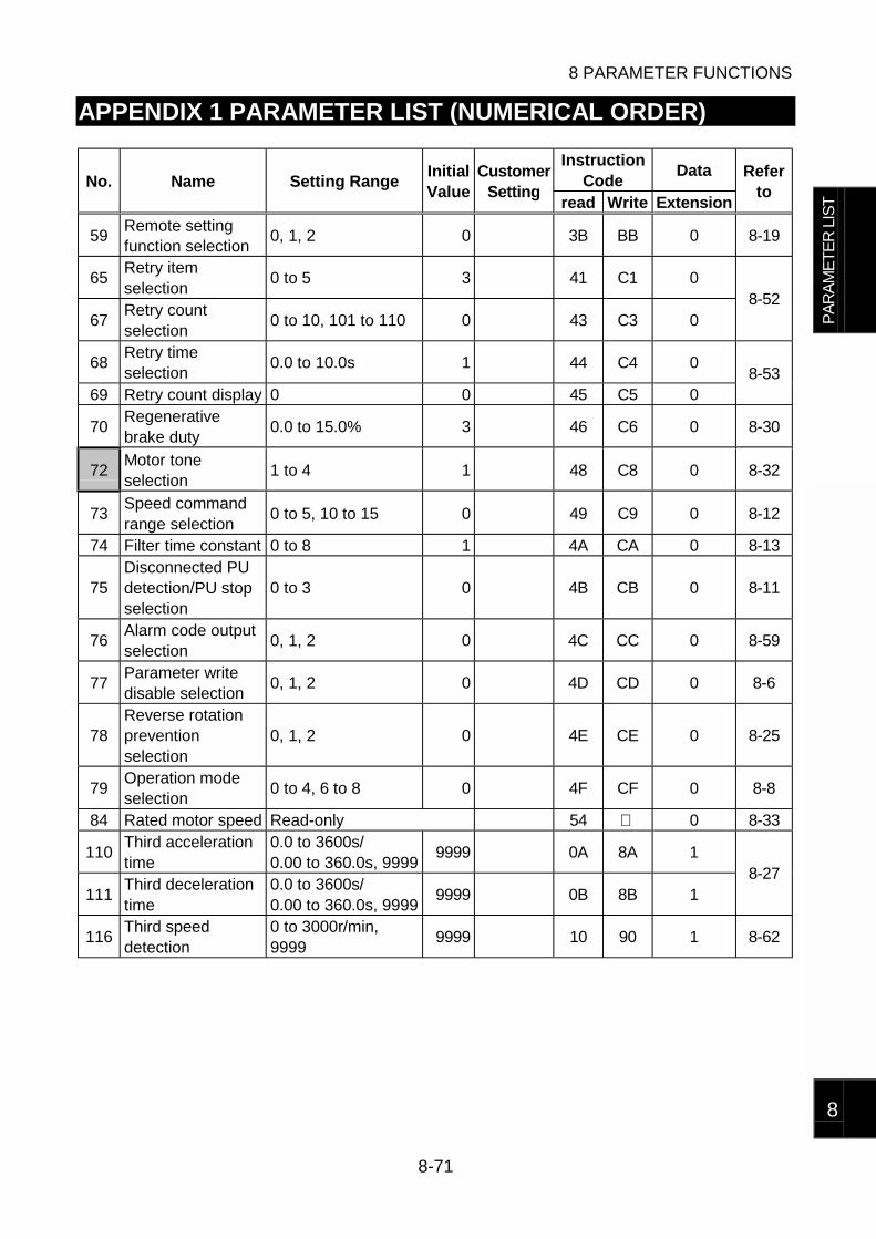
8 PARAMETER FUNCTIONS
8-71
8
APPENDIX 1 PARAMETER LIST (NUMERICAL ORDER)
InstructionCode
DataNo. Name Setting Range
InitialValue
CustomerSetting
read Write Extension
Referto
59Remote settingfunction selection
0, 1, 2 0 3B BB 0 8-19
65Retry itemselection
0 to 5 3 41 C1 0
67Retry countselection
0 to 10, 101 to 110 0 43 C3 08-52
68Retry timeselection
0.0 to 10.0s 1 44 C4 0
69 Retry count display 0 0 45 C5 08-53
70Regenerativebrake duty
0.0 to 15.0% 3 46 C6 0 8-30
72Motor toneselection
1 to 4 1 48 C8 0 8-32
73Speed commandrange selection
0 to 5, 10 to 15 0 49 C9 0 8-12
74 Filter time constant 0 to 8 1 4A CA 0 8-13
75Disconnected PUdetection/PU stopselection
0 to 3 0 4B CB 0 8-11
76Alarm code outputselection
0, 1, 2 0 4C CC 0 8-59
77Parameter writedisable selection
0, 1, 2 0 4D CD 0 8-6
78Reverse rotationpreventionselection
0, 1, 2 0 4E CE 0 8-25
79Operation modeselection
0 to 4, 6 to 8 0 4F CF 0 8-8
84 Rated motor speed Read-only 54 0 8-33
110Third accelerationtime
0.0 to 3600s/0.00 to 360.0s, 9999
9999 0A 8A 1
111Third decelerationtime
0.0 to 3600s/0.00 to 360.0s, 9999
9999 0B 8B 18-27
116Third speeddetection
0 to 3000r/min,9999
9999 10 90 1 8-62
PA
RA
ME
TE
R L
IST

8 PARAMETER FUNCTIONS
8-72
APPENDIX 1 PARAMETER LIST (NUMERICAL ORDER)
InstructionCode
DataNo. Name Setting Range
InitialValue
CustomerSetting
read Write Extension
Referto
117 Station number 0 to 31 0 11 91 1
118Communicationspeed
48, 96, 192 92 12 92 1
119Stop bitlength/data length
0, 1, 10, 11 1 13 93 1
120Parity checkpresence/absence
0, 1, 2 2 14 94 1
121Number ofcommunicationretries
0 to 10, 9999 1 15 95 1
122Communicationcheck time interval
0, 0.1 to 999.8,9999
0 16 96 1
123Waiting timesetting
0 to 150,9999
9999 17 97 1
124CR-LFpresence/absenceselection
0, 1, 2 1 18 98 1
8-35
128PID actionselection
0, 10, 11, 20, 21 0 1C 9C 1
129PID proportionalband
0.1 to 1000%,9999
100 1D 9D 1
130 PID integral time0.1 to 3600s,9999
1 1E 9E 1
131 Upper limit0.0 to 100.0%,9999
9999 1F 9F 1
132 Lower limit0.0 to 100.0%,9999
9999 20 A0 1
133PID action setpoint for PUoperation
0.00 to 100.0% 0 21 A1 1
134PID differentialtime
0.01 to 10.00s,9999
9999 22 A2 1
8-45
144Speed unit switch-over 2
0, 1 0 2C AC 1 8-55
150Output currentdetection level
0.0 to 200.0% 150 32 B2 1
151Output currentdetection time
0.0 to 10.0s 0 33 B3 18-63
156Stall preventionoperation selection
1 to 31 (odd number),101
1 38 B8 1 8-31
PA
RA
ME
TE
R L
IST

8 PARAMETER FUNCTIONS
8-73
8
APPENDIX 1 PARAMETER LIST (NUMERICAL ORDER)
InstructionCode
DataNo. Name Setting Range
InitialValue
CustomerSetting
read Write Extension
Referto
157OL signal outputtimer
0.0 to 25.0s 0 39 B9 1 8-59
158AM terminalfunction selection
Refer to manualdescription.
1 3A BA 1 8-64
160User group readselection
0, 1, 10, 11 0 00 80 2 8-6
171Actual operationhour meter clear
0 0 0B 8B 2 8-57
173User group 1registration
0 to 999 0 0D 8D 2
174User group 1deletion
0 to 999,9999
0 0E 8E 2
175User group 2registration
0 to 999 0 0F 8F 2
176User group 2deletion
0 to 999,9999
0 10 90 2
8-6
180RL terminalfunction selection
Refer to manualdescription.
0 14 94 2
181RM terminalfunction selection
Refer to manualdescription.
1 15 95 2
182RH terminalfunction selection
Refer to manualdescription.
2 16 96 2
183RT terminalfunction selection
Refer to manualdescription.
3 17 97 2
184AU terminalfunction selection
Refer to manualdescription.
4 18 98 2
185JOG terminalfunction selection
Refer to manualdescription.
5 19 99 2
186CS terminalfunction selection
Refer to manualdescription.
8 1A 9A 2
187MRS terminalfunction selection
Refer to manualdescription.
24 1B 9B 2
8-22
188RES terminaloperation selection
0, 1 0 1C 9C 2
189STF, STR terminaloperation selection
0, 1 0 1D 9D 28-23
PA
RA
ME
TE
R L
IST

8 PARAMETER FUNCTIONS
8-74
APPENDIX 1 PARAMETER LIST (NUMERICAL ORDER)
InstructionCode
DataNo. Name Setting Range
InitialValue
CustomerSetting
read Write Extension
Referto
190RUN terminalfunction selection
Refer to manualdescription.
0 1E 9E 2
191SU terminalfunction selection
Refer to manualdescription.
1 1F 9F 2
192IPF terminalfunction selection
Refer to manualdescription.
2 20 A0 2
193OL terminalfunction selection
Refer to manualdescription.
3 21 A1 2
194FU terminalfunction selection
Refer to manualdescription.
4 22 A2 2
195A, B, C terminalfunction selection
Refer to manualdescription.
99 23 A3 2
8-58
199User's initial valuesetting
0 to 999,9999
0 27 A7 2 8-7
232Multi-speed setting(speed 8)
0 to 3000r/min,9999
9999 28 A8 2
233Multi-speed setting(speed 9)
0 to 3000r/min,9999
9999 29 A9 2
234Multi-speed setting(speed 10)
0 to 3000r/min,9999
9999 2A AA 2
235Multi-speed setting(speed 11)
0 to 3000r/min,9999
9999 2B AB 2
236Multi-speed setting(speed 12)
0 to 3000r/min,9999
9999 2C AC 2
237Multi-speed setting(speed 13)
0 to 3000r/min,9999
9999 2D AD 2
238Multi-speed setting(speed 14)
0 to 3000r/min,9999
9999 2E AE 2
239Multi-speed setting(speed 15)
0 to 3000r/min,9999
9999 2F AF 2
8-18
244Cooling fanoperation selection
0, 1 0 34 B4 2 8-33
250Coasting-to-stopsetting
0.0 to 100.0s,9999
9999 3A BA 2 8-30
252 Override bias 0.0 to 200.0% 50 3C BC 2253 Override gain 0.0 to 200.0% 150 3D BD 2
8-13
PA
RA
ME
TE
R L
IST
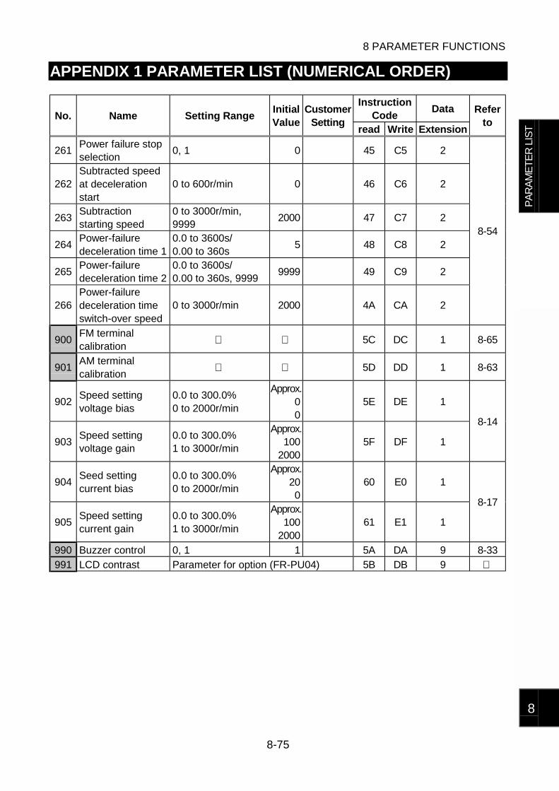
8 PARAMETER FUNCTIONS
8-75
8
APPENDIX 1 PARAMETER LIST (NUMERICAL ORDER)
InstructionCode
DataNo. Name Setting Range
InitialValue
CustomerSetting
read Write Extension
Referto
261Power failure stopselection
0, 1 0 45 C5 2
262Subtracted speedat decelerationstart
0 to 600r/min 0 46 C6 2
263Subtractionstarting speed
0 to 3000r/min,9999
2000 47 C7 2
264Power-failuredeceleration time 1
0.0 to 3600s/0.00 to 360s
5 48 C8 2
265Power-failuredeceleration time 2
0.0 to 3600s/0.00 to 360s, 9999
9999 49 C9 2
266Power-failuredeceleration timeswitch-over speed
0 to 3000r/min 2000 4A CA 2
8-54
900FM terminalcalibration
5C DC 1 8-65
901AM terminalcalibration
5D DD 1 8-63
902Speed settingvoltage bias
0.0 to 300.0%0 to 2000r/min
Approx.00
5E DE 1
903Speed settingvoltage gain
0.0 to 300.0%1 to 3000r/min
Approx.100
20005F DF 1
8-14
904Seed settingcurrent bias
0.0 to 300.0%0 to 2000r/min
Approx.200
60 E0 1
905Speed settingcurrent gain
0.0 to 300.0%1 to 3000r/min
Approx.100
200061 E1 1
8-17
990 Buzzer control 0, 1 1 5A DA 9 8-33
991 LCD contrast Parameter for option (FR-PU04) 5B DB 9
PA
RA
ME
TE
R L
IST

REVISIONS*The manual number is given on the bottom left of the back cover.
Print Date *Manual Number RevisionFeb., 2001 IB(NA)-0600056-A First edition


![Theory Questions Marks : 30 · equilibrium position to the fully stretched position [1.0]. Force, F = k(L s-L) Work, W = 0.5k(L s-L)2 U = 0.5k(L s-L)2 Vibrational energy per mole](https://img.dokumen.tips/doc/110x75/5f9a02ff87ac4d722e53613a/theory-questions-marks-30-equilibrium-position-to-the-fully-stretched-position.jpg)