Embed Size (px)
Citation preview

M a t e r i a l s
Swiss Federal
Institute of Technology
Zürich
Nonmetallic Materials
Brandon E. Bürgler
Nonmetallic Inorganic Materials
ETH Zürich
Single Chamber Solid Oxide Fuel Cells (SC-SOFC)
Thursday, March 19th, 2004

M a t e r i a l s
Swiss Federal
Institute of Technology
Zürich
Nonmetallic Materials
Outline
• Single Chamber SOFCs
• Experiments
• Modelling Issues
• Outlook

SC-SOFC
M a t e r i a l s
Swiss Federal
Institute of Technology
Zürich
Nonmetallic Materials
• Cathode and anode exposed to same gas mixture of fuel and oxidant
• Selectivity of electrodes for either oxidation or reduction reaction
Single Chamber SOFC
OCV
O2 + N2
H2
+ N2
H2O
O2
ocvCH4 + O2 + N2
CO + CO2 + N2 + H2
CH4 + N2 + O2
Conventional SOFC Single Chamber SOFC

SC-SOFC
M a t e r i a l s
Swiss Federal
Institute of Technology
Zürich
Nonmetallic Materials
SC-SOFC ↔ conventional SOFC
Advantages
• Simplified cell sealing• Elimination of complex flow field structures• Fast start-up possible• Costs
Challenges
• Non-equilibrium gas mixture (explosive from 5 to 15% CH4 in air)
• Fuel utilisation?• Parasitic chemical reactions
SC-SOFC
M a t e r i a l s
Swiss Federal
Institute of Technology
Zürich
Nonmetallic Materials
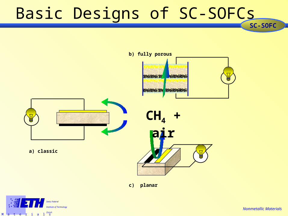
Basic Designs of SC-SOFCs
CH4 + air
a) classic
b) fully porous
c) planar

SC-SOFC
M a t e r i a l s
Swiss Federal
Institute of Technology
Zürich
Nonmetallic Materials
Open Questions & Aims
• Which parameters influence the OCV and the
maximum power output?
• Fundamental model of SC-SOFC including non-
ideal electrodes and CH4 as the fuel
• High performance SC-SOFC

Experiments
M a t e r i a l s
Swiss Federal
Institute of Technology
Zürich
Nonmetallic Materials
Measurement Setup
CH4Air
CH4AirExhaust
Thermocouple
U
I
Electrical characterisation:
Galvanostatic 4-point
measurements
Temperature:• 400 - 700°C• dT/dt < 2.5°C/min
CH4-air mixture:
• Air: 100-400ml/min
• CH4: 100ml/min,
moistened (~3% H2O)
Experiments
M a t e r i a l s
Swiss Federal
Institute of Technology
Zürich
Nonmetallic Materials
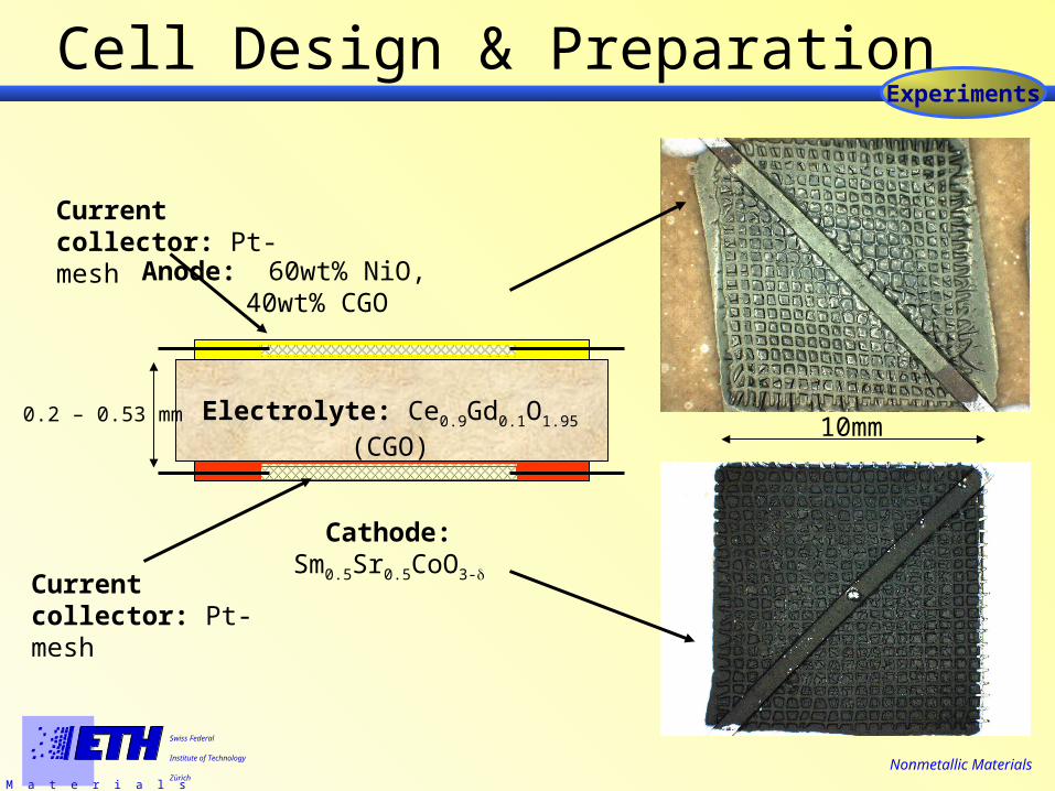
Cell Design & Preparation
Current collector: Pt-mesh
Electrolyte: Ce0.9Gd0.1O1.95 (CGO)
Anode: 60wt% NiO,40wt% CGO
Cathode: Sm0.5Sr0.5CoO3-
10mm 0.2 – 0.53 mm
Current collector: Pt-mesh

Experiments
M a t e r i a l s
Swiss Federal
Institute of Technology
Zürich
Nonmetallic Materials
Fuel Cell Cross Section
Cathode (~140 m)
Anode (~160 m)
Electrolyte (~330m)
Pt-mesh, longitudinal section (~80 m)
Pt-mesh, cross section (~80 m )

Experiments
M a t e r i a l s
Swiss Federal
Institute of Technology
Zürich
Nonmetallic Materials
Open Circuit Voltage
MS14 (0.19mm electrolyte):
Reduction of NiO
strong heat generation
300 350 400 450 500 550 600 650 700 7500.0
0.2
0.4
0.6
0.8
1.0
OC
V [V
olt]
Temperature [°C]
100ml/min air (heating) 100ml/min air (cooling)

Experiments
M a t e r i a l s
Swiss Federal
Institute of Technology
Zürich
Nonmetallic Materials
U-I Characteristics at different flow
0 500 1000 1500 20000.0
0.2
0.4
0.6
0.8
Current Density [mA/cm2]
Vol
tage
[V]
0
100
200
300
400
500P
ower D
ensity [m
W/cm
2]T = 600°C

Experiments
M a t e r i a l s
Swiss Federal
Institute of Technology
Zürich
Nonmetallic Materials
U-I Characteristics at different flow
0 500 1000 1500 20000.0
0.2
0.4
0.6
0.8
100ml/min air
Current Density [mA/cm2]
Vol
tage
[V]
0
100
200
300
400
500P
ower D
ensity [m
W/cm
2]T = 600°C

Experiments
M a t e r i a l s
Swiss Federal
Institute of Technology
Zürich
Nonmetallic Materials
U-I Characteristics at different flow
0 500 1000 1500 20000.0
0.2
0.4
0.6
0.8
100ml/min air 200ml/min air
Current Density [mA/cm2]
Vol
tage
[V]
0
100
200
300
400
500P
ower D
ensity [m
W/cm
2]T = 600°C

Experiments
M a t e r i a l s
Swiss Federal
Institute of Technology
Zürich
Nonmetallic Materials
U-I Characteristics at different flow
0 500 1000 1500 20000.0
0.2
0.4
0.6
0.8
100ml/min air 200ml/min air 300ml/min air
Current Density [mA/cm2]
Vol
tage
[V]
0
100
200
300
400
500P
ower D
ensity [m
W/cm
2]T = 600°C

Experiments
M a t e r i a l s
Swiss Federal
Institute of Technology
Zürich
Nonmetallic Materials
Pmax = 440 mW/cm2 @ 100 ml/min CH4 and
200 ml/min Air at 600°C
U-I Characteristics at different flow
0 500 1000 1500 20000.0
0.2
0.4
0.6
0.8
100ml/min air 200ml/min air 300ml/min air 400ml/min air
Current Density [mA/cm2]
Vol
tage
[V]
0
100
200
300
400
500P
ower D
ensity [m
W/cm
2]T = 600°C

Experiments
M a t e r i a l s
Swiss Federal
Institute of Technology
Zürich
Nonmetallic Materials
U-I characteristic at different Temperatures
0 500 1000 15000.0
0.2
0.4
0.6
0.8
500°C
Current Density [mA/cm2]
Vo
ltag
e [V
olt]
0
100
200
300
400P
ow
er D
en
sity [mW
/cm2]
fAir = 200 ml/min

Experiments
M a t e r i a l s
Swiss Federal
Institute of Technology
Zürich
Nonmetallic Materials
U-I characteristic at different Temperatures
0 500 1000 15000.0
0.2
0.4
0.6
0.8
500°C 600°C
Current Density [mA/cm2]
Vo
ltag
e [V
olt]
0
100
200
300
400P
ow
er D
en
sity [mW
/cm2]
fAir = 200 ml/min

Experiments
M a t e r i a l s
Swiss Federal
Institute of Technology
Zürich
Nonmetallic Materials
U-I characteristic at different Temperatures
0 500 1000 15000.0
0.2
0.4
0.6
0.8
500°C 600°C 700°C
Current Density [mA/cm2]
Vo
ltag
e [V
olt]
0
100
200
300
400P
ow
er D
en
sity [mW
/cm2]
fAir = 200 ml/min

Experiments
M a t e r i a l s
Swiss Federal
Institute of Technology
Zürich
Nonmetallic Materials
Open Circuit Voltage
400 500 600 7000.0
0.1
0.2
0.3
0.4
0.5
0.6
0.7
0.8
0.9
OC
V [
V]
Temperature [°C]
100ml/min air 200ml/min air 300ml/min air 400ml/min air
400 500 600 7000
50
100
150
200
250
300
max
. P
ower
Den
sity
[m
W/c
m2 ]
Temperature [°C]
100ml/min air 200ml/min air 300ml/min air 400ml/min air

Experiments
M a t e r i a l s
Swiss Federal
Institute of Technology
Zürich
Nonmetallic Materials
Electrode Temperatures at OCV
100 200 300 400500
600
700
800
Tnorm
=600°C
Tnorm
=500°C
Tnorm
=700°C
Cathode Temperature Anode Tempearature
Air Flow [ml/min]
Te
mp
era
ture
[°C
]
Pronounced heat generation on the anode
Electrolyte thickness: 390m

Experiments
M a t e r i a l s
Swiss Federal
Institute of Technology
Zürich
Nonmetallic Materials
Conclusions from Experiments
• Cells operate at T > 500°C
• Optimum conditions for maximum Power
output at T= 600°C and fair = 300 ml/min
• Pronounced heat generation at the anode

Modelling
M a t e r i a l s
Swiss Federal
Institute of Technology
Zürich
Nonmetallic Materials
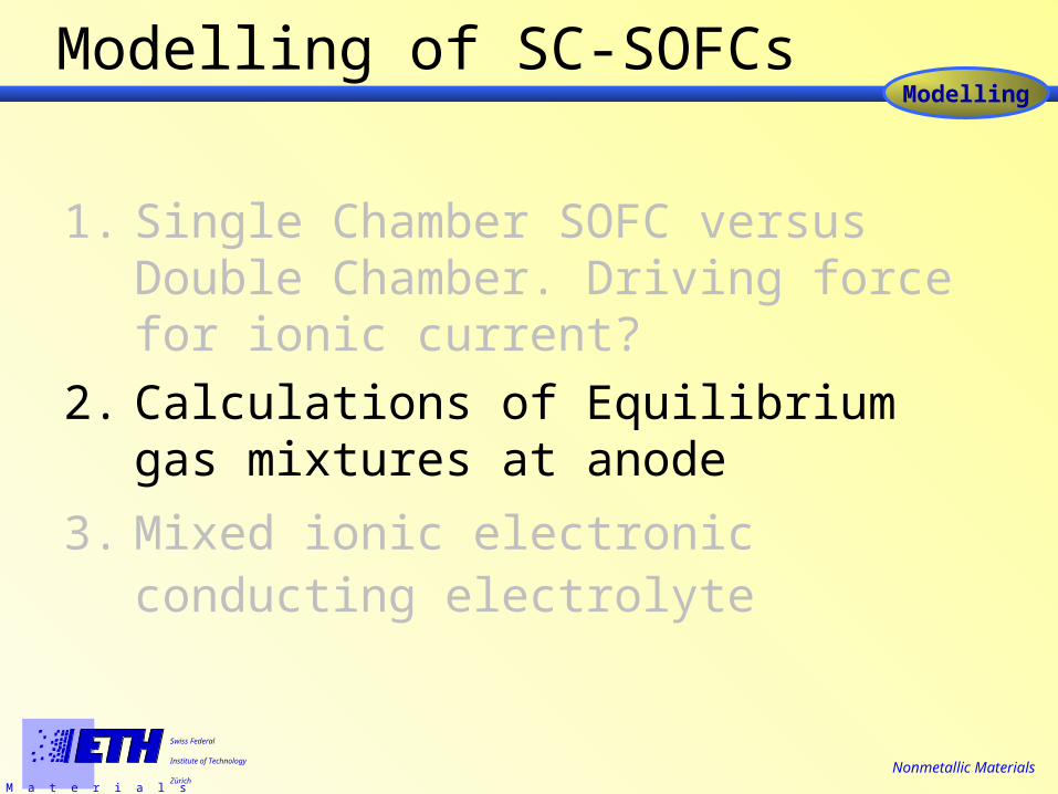
Modelling of SC-SOFCs
1. Single Chamber SOFC versus Double Chamber: Driving force for ionic current?
2. Calculations of Equilibrium gas mixtures at anode
3. Mixed ionic electronic conducting electrolyte

Modelling
M a t e r i a l s
Swiss Federal
Institute of Technology
Zürich
Nonmetallic Materials
What is the driving force for the ionic current?
Assumptions:
-Hydrogen as fuel, air as oxidant
-Reversible and perfectly selective electrodes for H2 or O2
-Electrolyte only O2--conductor
Riess, I., van der Put, P. J. (1995). "Solid oxide fuel cells operating on uniform mixtures of fuel and air." Solid State Ionics 82: 1-4.
Cathode
½ O2 (gas) + 2e- → O2- (C)
Anode
½ H2 (gas) → H+ (A) + 2e-
O2- (SE/A) + 2 H+ (A)→ H2O (gas)(C)
(A) (SE/A)

Modelling
M a t e r i a l s
Swiss Federal
Institute of Technology
Zürich
Nonmetallic Materials
Calculation of O2-
Combination of (7), (8) and (9) yields
½ O2 (gas) + 2e- ↔ O2- (C)
½ H2 (gas) ↔ H+ (A) + e-
O2- (SE/A) + 2 H+ (A)↔ H2O (gas)
GOCV =
2q
The Nernst Voltage is the same for
SC- and conventional SOFCs

Modelling
M a t e r i a l s
Swiss Federal
Institute of Technology
Zürich
Nonmetallic Materials
Comment
• Electrodes are not ideally selective nor reversible.
• Direct oxidation of the fuel (=parasitical) lowers OCV.
• Improving selectivity of the electrodes will improve efficiency and reduce fuel waste.

Modelling
M a t e r i a l s
Swiss Federal
Institute of Technology
Zürich
Nonmetallic Materials
Operation Principles of a SC-SOFC
O2 + 4e- 2O2-
p(O2 )
p(O2 )
OCV
CH4 + air
CH4 + air
H2 + O2- 2H2O + 2e-
CO + O2- CO2 + 2e-
CH4 + 1/2O2 2H2 + CO
cathode2anode2
p(O )kTOCV = ln
4q p(O )
partial oxidation of methane
Modelling
M a t e r i a l s
Swiss Federal
Institute of Technology
Zürich
Nonmetallic Materials
Modelling of SC-SOFCs
1. Single Chamber SOFC versus Double Chamber. Driving force for ionic current?
2. Calculations of Equilibrium gas mixtures at anode
3. Mixed ionic electronic conducting electrolyte

Modelling
M a t e r i a l s
Swiss Federal
Institute of Technology
Zürich
Nonmetallic Materials
Calculation of equilibrium gas mixtures
Input:
T, Composition
X(C), X(O), X(H)
Minimisation of Gibbs
Free Energy
Output:
Concentrations of species: CH4, O2, H2, CO,
CO2
Thermocalc™
Basic idea:
Anode: Equilibrium reached very fast. pO2 ≈ 10-26 atm
Cathode: non-equilibrium gas mixtures remains unreacted
pO2 ≈ 0.05 – 0.17 atm
CH4 + Air

Modelling
M a t e r i a l s
Swiss Federal
Institute of Technology
Zürich
Nonmetallic Materials
Equilibria for Different CH4:O2 Ratios
0.0 0.2 0.4 0.6 0.8 1.0
0.0
0.2
0.4
0.6
0.8
1.0
frac
tion
in g
as p
hase
x(O)
CH4
CO
CO2
H2
H2O
O2
Suitable mixtures for SC-SOFCs
X (O)
T = 600°C

Modelling
M a t e r i a l s
Swiss Federal
Institute of Technology
Zürich
Nonmetallic Materials
Carbon deposition at low x(O)
0.0 0.2 0.4 0.6 0.8 1.00.0
0.2
0.4
0.6
0.8
1.0
mo
lar
fra
cti
on
x(O)
solid
fCH4 = 100 ml/min
fAir= 100 ml/min
Carbon deposition at low x(O)!!
gas

Modelling
M a t e r i a l s
Swiss Federal
Institute of Technology
Zürich
Nonmetallic Materials
Modelling of SC-SOFCs
1. Single Chamber SOFC versus Double Chamber. Driving force for ionic current?
2. Calculations of Equilibrium gas mixtures at anode
3. Mixed ionic electronic conducting electrolyte

Modelling
M a t e r i a l s
Swiss Federal
Institute of Technology
Zürich
Nonmetallic Materials
high pO2 conductance predominantly ionic.
low pO2 partial reduction n-type semiconduction Electronic conductivity ~ [Ce3+] ~ pO2
-1/4.
D. Schneider, M. Gödickemeier and L.J. GaucklerJ. of Electroceramics, 1, [2], (1997), 165-172
Conductivity of Ce0.8Sm0.2O1.9-x vs. pO2
Electrolyte is a mixed ionic electronic conductor
28 24 20 16 12 8 4 01
10
873 K
973 K
1073 K
tot [
S/m
]
-log (pO
2
/atm)
-1/4

Modelling
M a t e r i a l s
Swiss Federal
Institute of Technology
Zürich
Nonmetallic Materials
Transport Model for MIEC- SOFC electrolyte
Gödickemeier, M., Sasaki, K. and Gauckler, L. J. (1997)."Electrochemical Characteristics of Cathodes in Solid Oxide Fuel Cells based on Ceria Electrolytes."J. Electrochem. Soc. 144(5): 1635-1646.
j kT q N
j kT q n
i iNx i x
e enx i x
2
2
Nx
0
nn
qkT th
L V MC0
exp( ( ))
for n p O ( )2
14
V MC V V Vth Nernst th C th A( ) , , jV MC V
L
V
V MC Ve e
L th CellqkT Cell
qkT th Cell
( ) exp( )
exp( ( ( ) ))
1
1j V MC V
Li ith Cell ( )
MIEC
p(O2)low
p(O2)0
p(O2)L
p(O2)high
e
0 L
x
O 2 -
< < <
VCell
air side
fuel side
load
A Cext A ext C
1. transport equations
2. defect distribution
3. electrode overpotentials
jx
jx
i e 0 0

Modelling
M a t e r i a l s
Swiss Federal
Institute of Technology
Zürich
Nonmetallic Materials
Partial currents in MIEC – SOFC electrolytes
ionic & electronic current It
cell current It
Vcell
Vcell = VOC
-Ie = Ii
open circuit voltage
Vth
electronic current Ie
Vcell
electronic current Ie Ie(Vocv)
Vcell = 0Ie = 0
IeRe
Vcell
ionic current Ii
ionic current Ii
Ii(Vocv)
Vcell = Vth, app
Ii = 0
IiRi +Vth,C+ Vth,A

Modelling
M a t e r i a l s
Swiss Federal
Institute of Technology
Zürich
Nonmetallic Materials
Conclusions
1. Single Chamber SOFC versus Double Chamber. Driving force for ionic current?
2. Calculations of Equilibrium gas mixtures at anode
3. Mixed ionic electronic conducting electrolyte
4. Thermal Reactor
----

M a t e r i a l s
Swiss Federal
Institute of Technology
Zürich
Nonmetallic Materials
Acknowledgements
• Prof. Dr. L. J. Gauckler• A. Nicholas Grundy• Michel Prestat• SOFC group• The entire Nonmets Group
Diploma students• Marco Siegrist• Srdan Vasic

M a t e r i a l s
Swiss Federal
Institute of Technology
Zürich
Nonmetallic Materials
Thank you for your kind attention