Embed Size (px)
Citation preview

LX Wireless System
27D8654 (BK) 2002, Shure Incorporated
Printed in U.S.A.
LX Wireless SystemUser Guide

English
1
READ ME FIRST!To get your system up and running in just a few minutes, follow the simple in-
structions on this page. For more detailed information, refer to the sections ofthis guide that apply to your system.
Receiver Connections1. Attach the antennas to the receiver antenna connectors.
2. Connect the AC power adapter to the receiver power connector; then plug it into anac electrical outlet.
3. Connect the receiver audio output to the sound system, using either a low- or high-impedance audio cable.
Transmitter Connections1. Open the transmitter battery compartment and insert a fresh 9-volt alkaline
battery. Observe proper battery polarity ( “+/–”).
2. If you are using a body-pack transmitter, connect the microphone or WA302 instru-ment cable to the 4-pin connector on the transmitter.
Operating the System1. Press the receiver POWER switch. The green POWER light on the receiver
illuminates.
2. Set the transmitter PWR/OFF switch to PWR and the ON/MUTE switch to ON. Oneof the three lights on the transmitter illuminates, indicating both that the transmitteris on and the amount of battery life remaining. Two sets of five RF level lights on thereceiver will also glow to indicate the strength of the received signal. The more lightsglowing, the stronger the signal.
3. Have someone talk or sing into the microphone, or play the musical instrument con-nected to the transmitter. The audio level will be indicated as follows:
- Green lights (3) glowing indicates normal operation.
- Amber light glowing indicates approaching audio overload (should only occurduring loud signals).
- Red light glowing steadily indicates audio overload. If this happens, reduce thetransmitter gain until it flickers only during the loudest signals. Refer to the Trans-mitter Audio Gain Adjustment section of this guide.
4. Adjust the receiver LEVEL control until the output level is compatible with the mixeror amplifier input. In most cases, this control should be set fully clockwise.
YOU ARE NOW READY TO PERFORM!
IMPORTANT: Every wireless microphone installation is a unique situation, and canpresent a variety of problems. Never attempt a live performance without first conduct-ing a “walkthrough” test of the system in the performing area. If major changes (addi-tional wireless systems or intercoms, relocation of scenery, etc.) have been madesince the last walk–through test, check the wireless system again—as close to perfor-mance time as possible.
Wireless
2
TABLE OF CONTENTS
SYSTEM COMPONENTS 5. . . . . . . . . . . . . . . . . . . . . . . . . . . . . . . . . . . . . . . . . . . . . . . SYSTEM FEATURES 6. . . . . . . . . . . . . . . . . . . . . . . . . . . . . . . . . . . . . . . . . . . . . . . . . . . LX1 BODY-PACK TRANSMITTER FEATURES, CONTROLS & INDICATORS 7. . . LX2 HAND-HELD TRANSMITTER FEATURES, CONTROLS & INDICATORS 8. . LX3 RECEIVER FEATURES, CONTROLS & INDICATORS 9. . . . . . . . . . . . . . . . . . LX4 DIVERSITY RECEIVER FEATURES, CONTROLS & INDICATORS 10. . . . . . . RECEIVER MOUNTING 11. . . . . . . . . . . . . . . . . . . . . . . . . . . . . . . . . . . . . . . . . . . . . . . .
Single Rack Mounted Receiver 11. . . . . . . . . . . . . . . . . . . . . . . . . . . . . . . . . . . . . . Double Rack Mounted Receivers 11. . . . . . . . . . . . . . . . . . . . . . . . . . . . . . . . . . . .
RECEIVER CONNECTIONS 12. . . . . . . . . . . . . . . . . . . . . . . . . . . . . . . . . . . . . . . . . . . . TRANSMITTER SETUP 13. . . . . . . . . . . . . . . . . . . . . . . . . . . . . . . . . . . . . . . . . . . . . . . .
LX1 Body-Pack Transmitter Battery Installation 13. . . . . . . . . . . . . . . . . . . . . . . . LX2 Hand-Held Microphone-Transmitter Battery Installation 13. . . . . . . . . . . . . Checking the Transmitter Battery 14. . . . . . . . . . . . . . . . . . . . . . . . . . . . . . . . . . . . Connecting a Lavalier Microphone or Instrument Cable to the LX1 14. . . . . . . Attaching the LX1 to a Belt or Guitar Strap 15. . . . . . . . . . . . . . . . . . . . . . . . . . . . Installing the WA555 Grip/Switch Cover Accessory on the LX2 15. . . . . . . . . .
OPERATING LX1 BODY-PACK SYSTEMS 16. . . . . . . . . . . . . . . . . . . . . . . . . . . . . . . . OPERATING THE LX2 HAND-HELD SYSTEM 17. . . . . . . . . . . . . . . . . . . . . . . . . . . . GAIN AND SQUELCH ADJUSTMENT 18. . . . . . . . . . . . . . . . . . . . . . . . . . . . . . . . . . . .
Adjusting the Transmitter Audio Gain Level 18. . . . . . . . . . . . . . . . . . . . . . . . . . . Adjusting the Receiver Squelch Control 19. . . . . . . . . . . . . . . . . . . . . . . . . . . . . .
TIPS FOR ACHIEVING OPTIMUM PERFORMANCE 19. . . . . . . . . . . . . . . . . . . . . . . TROUBLESHOOTING 20. . . . . . . . . . . . . . . . . . . . . . . . . . . . . . . . . . . . . . . . . . . . . . . . . SPECIFICATIONS 21. . . . . . . . . . . . . . . . . . . . . . . . . . . . . . . . . . . . . . . . . . . . . . . . . . . . . FURNISHED ACCESSORIES 22. . . . . . . . . . . . . . . . . . . . . . . . . . . . . . . . . . . . . . . . . . . OPTIONAL ACCESSORIES 22. . . . . . . . . . . . . . . . . . . . . . . . . . . . . . . . . . . . . . . . . . . . REPLACEMENT PARTS 23. . . . . . . . . . . . . . . . . . . . . . . . . . . . . . . . . . . . . . . . . . . . . . . LICENSING INFORMATION 23. . . . . . . . . . . . . . . . . . . . . . . . . . . . . . . . . . . . . . . . . . . .

English
3
SYSTEM COMPONENTS (FIGURE 1)
LX1
ÑÑÑÑÑÑÑÑÑÑÑÑÑÑÑÑÑÑÑÑÑÑÑÑÑÑÑÑÑÑÑÑÑÑÑ
ÑÑÑ
ÑÑÑÑÑÑ
ÑÑÑÑÑÑÑÑ
ÑÑÑÑÑÑÑÑÑÑÑÑÑÑÑÑ
ÑÑÑÑÑÑÑÑÑÑÑÑÑÑÑÑÑÑÑÑÑ
ÑÑÑ
ÑÑÑÑÑÑÑÑÑÑÑÑÑÑ
ÑÑÑÑÑÑÑÑÑÑÑÑÑ
ÑÑÑÑÑÑÑÑÑÑ
ÑÑÑÑÑÑÑÑÑÑÑÑÑÑÑÑÑÑÑÑÑÑÑÑÑÑÑÑÑÑÑÑÑÑÑÑ
ÑÑÑÑÑÑ
ÑÑÑÑÑÑ
ÑÑÑÑÑÑÑÑÑÑÑÑÑÑÑÑÑÑÑÑÑÑÑÑÑÑÑ
LEVEL POWER
LX4
ÑÑÑÑÑÑÑÑÑÑÑÑÑÑÑÑÑÑÑÑÑÑÑÑÑÑÑÑÑÑÑÑÑÑÑÑÑÑÑÑÑÑÑÑÑÑÑÑÑÑÑÑÑÑÑÑÑÑÑÑÑÑÑÑÑÑÑ
ÑÑÑÑÑÑÑÑÑÑ
ÑÑÑÑÑÑÑÑÑÑÑÑÑÑÑÑÑÑÑÑÑÑÑÑÑÑÑÑÑÑÑÑÑÑÑÑÑÑÑÑÑÑÑÑÑÑÑÑÑÑÑÑÑÑÑÑÑÑÑÑÑÑÑÑÑÑÑÑÑÑÑÑÑÑÑÑÑÑÑÑÑÑ
RF A RF B AUDIOSQUELCH
DIVERSITYMARCADÑÑ
ÑÑÑÑÑÑÑÑÑ
ÑÑÑÑÑÑÑÑÑÑ
ÑÑÑÑÑÑÑÑÑÑÑ
ÑÑÑÑÑÑÑÑÑÑÑÑÑÑÑÑÑÑÑ
ÑÑÑÑÑÑ
ÑÑÑÑÑÑÑÑ
ÑÑÑÑÑÑÑÑÑ
LX2
ÑÑÑÑÑÑÑÑÑÑÑÑÑÑÑÑÑÑÑÑÑÑÑÑÑÑÑÑÑÑÑÑÑÑÑRECEIVERÑ ÑÑÑÑÑÑÑÑÑÑÑÑÑÑÑÑÑÑÑÑÑÑÑÑÑÑÑÑÑÑÑÑÑÑÑÑÑÑÑÑÑÑÑÑÑÑÑÑÑÑÑÑÑÑ
ÑÑÑÑÑÑÑÑÑÑÑÑÑÑÑÑÑ
ÑÑÑÑÑÑÑÑÑÑÑÑÑÑÑÑÑÑÑÑÑÑÑÑÑÑÑÑÑÑÑÑÑÑÑÑÑÑÑÑÑÑÑÑÑÑÑÑÑÑÑÑÑÑÑÑÑÑÑÑÑÑÑÑÑÑÑÑÑÑÑÑÑÑÑÑÑÑÑÑÑÑÑ
RF AUDIOSQUELCH LEVEL POWER
LX3
WIRELESS
LX WIRELESS MICROPHONE SYSTEM COMPONENTSFIGURE 1
Your LX Wireless Microphone System features a MARCAD fixed frequency diver-sity receiver operating in the VHF band between 169 and 240 MHz. Up to 12 LX wire-less systems can be operated simultaneously in a single installation. Each LX systemcontains a combination of the following items:
• One of the following transmitters:
LX1 Body-Pack Transmitter, with your choice of instrument cable or microphone,
or
LX2 Hand-Held Microphone-Transmitter with your choice of interchangeable micro-phone heads:
- SM58 cardioid dynamic microphone
- BETA 58 supercardioid premium dynamic microphone
- SM87 supercardioid condenser microphone
- BETA 87supercardioid premium condenser microphone
• One of the following half-rack size receivers:
LX3 Receiver
or
LX4 Diversity Receiver
• Both single and dual rack-mounting hardware
• One antenna (LX3 systems) or two antennas (LX4 systems)
• One of the following ac power adapters: PS40, PS40E, or PS40UK.

Wireless
4
SYSTEM FEATURES
Shure LX Wireless Systems offer a number of exceptional features, including:
• Exclusive Shure MARCAD Circuitry (LX4). MARCAD (MAximum Ratio Combin-ing Audio Diversity) circuitry constantly monitors signals from both receiver sectionsand combines them to create a single output signal. The result is improved receptionand exceptional freedom from dropouts.
• Half-Rack Receiver Size. The LX3 and LX4 receivers interface with the HR (half-rack) format, and are supplied with both single and dual rack-mount hardware. Anoptional WA503 accessory kit lets you front-mount antennas.
• Power/Battery Fuel Gauge. The LX1 and LX2 transmitters include a three-lightgauge that indicates both “power on” and the amount of battery life remaining. (Referto the Checking the Transmitter Battery section.)
• Dual RF Level Meters (LX4). Instead of a conventional single RF meter, the LX4receiver has two meters, one for each antenna. The dual meters indicate receivedsignal strength at each antenna, and make it easier to identify and troubleshoot RF“dead spots.”
• Audio Metering. A five-light audio meter helps to optimize transmitter gain settingand lets you monitor audio level during operation.
• True Guitar Sound. Guitar players demanding the highest degree of sound qualityand reliability will appreciate the low noise and uncolored sound of the LX WirelessSystem.
• Noise Squelch. This circuit analyzes signal quality instead of signal strength. Thisvirtually eliminates the possibility of annoying noise bursts coming through your re-ceiver.
• Body-Pack Transmitter Belt Clip. The belt clip has a wider contact surface for abetter grip, and firmly holds thinner, more slippery materials. It can be removed orinverted for special positioning.
• Grip/Switch Cover Accessory. The unbreakable WA555 grip/switch cover acces-sory, supplied with all LX2 hand-held microphone-transmitters, prevents accidentalmovement of the power and mute switches and provides a “grip” feel.
• Compact Power Adapter. The supplied ac power adapter incorporates small, in-line transformers that save space on ac power strips. It also has mounting tabs soit can be secured to any surface, as well as locking dc power connectors to preventaccidental disconnection from the receiver.

English
5
LX1 BODY-PACK TRANSMITTER FEATURES, CONTROLS, & INDICATORS (FIGURE 2)
Ñ
ÑÑÑÑÑÑÑÑÑÑÑÑÑÑÑÑ
ÑÑÑÑÑÑÑÑÑÑÑÑÑÑÑÑÑ
ÑÑÑÑÑÑÑÑÑÑÑÑ
ÑÑÑÑÑÑÑÑÑÑÑÑ
ÑÑÑÑÑÑÑÑÑÑÑÑÑÑÑÑ
ÑÑÑÑÑÑÑÑÑÑÑÑ
ÑÑÑÑÑÑÑÑÑÑÑÑÑÑÑÑ
ÑÑÑÑÑÑÑÑÑÑÑÑ
ÑÑÑÑÑ
Ñ
ÑÑÑ
Ñ
ÑÑÑÑÑÑÑÑÑÑ
ÑÑÑÑÑÑÑÑÑÑÑÑ
ÑÑÑÑÑÑÑÑ
ÑÑÑÑÑÑÑÑ
ÑÑÑÑÑÑÑÑÑÑ
Ñ
ÑÑÑÑÑÑÑÑÑÑÑÑÑÑ
ÑÑÑÑÑÑÑÑÑÑÑÑÑÑÑÑ
ÑÑÑÑÑÑÑÑÑÑÑÑÑÑÑÑÑÑÑÑÑÑÑÑÑÑÑÑÑÑ
ÑÑÑÑÑÑÑ
ÑÑÑÑÑÑÑÑÑÑÑÑ
ÑÑÑÑ
ÑÑÑÑÑÑ
ÑÑÑ
ÑÑÑ
ÑÑÑÑÑÑÑÑÑÑÑÑÑÑÑÑÑÑÑÑÑÑÑÑÑÑÑÑÑÑÑÑÑÑÑ
ÑÑÑÑÑÑÑÑÑÑÑÑÑÑÑÑÑÑÑÑÑÑÑÑÑÑÑÑÑÑÑÑÑÑÑÑ
ÑÑÑÑÑÑÑÑÑ
ÑÑÑÑÑÑÑÑÑÑÑÑÑÑ ÑÑÑÑÑÑÑÑÑÑÑÑÑÑÑÑÑÑÑÑÑÑÑÑÑÑÑÑÑÑÑÑÑÑÑ
ÑÑÑÑÑÑÑÑÑÑÑÑÑÑ
ÑÑÑÑÑÑÑÑÑÑÑ
1 2
3
4 5
6 7
8
LX1 BODY-PACK TRANSMITTER FEATURES, CONTROLS & INDICATORSFIGURE 2
1. Antenna. A flexible wire antenna is permanently attached to the bottom of the LX1body-pack transmitter. For best operation, the antenna must hang in the verticalposition, and should not be coiled or bundled.
2. Battery Compartment. Hinged cover on bottom surface exposes the battery. Referto the Body-Pack Transmitter Battery Installation section.
3. Audio Gain Control. Allows audio level adjustment to accommodate varioussound sources (e.g., singing, speaking, or playing an instrument). A small screw-driver is supplied to make adjustments (see the Setting Audio Level section).
4. Input Jack. This is a Mini- connector (TA4F) that provides connection with a varietyof lavalier and headset microphone cables, and the Shure WA302 instrumentadapter cable.
5. Power/Battery Fuel Gauge. When the Power switch is turned to the PWR position,one or two of the three lights on the transmitter illuminates, indicating power to theunit. The color of the glowing light(s) indicates the amount of battery life remaining.Refer to the Checking the Transmitter Battery section.
6. Belt Clip. Allows the transmitter to be easily worn on a belt, waistband or guitarstrap.
7. Mic On/Mute Switch. “Mutes” the transmitter to prevent unwanted sounds from be-ing picked up by the receiver without turning the transmitter off.
8. Power Switch. Turns transmitter power on and off.

Wireless
6
LX2 HANDHELD MICROPHONE-TRANSMITTERFEATURES, CONTROLS, & INDICATORS (FIGURE 3)
ÑÑÑÑÑ
ÑÑÑÑÑÑÑÑÑÑÑÑÑÑÑÑÑÑÑÑÑÑÑÑÑÑ
ÑÑÑÑÑÑ
ÑÑÑÑÑÑÑÑÑÑ
ÑÑÑÑÑÑÑÑÑÑÑÑÑÑÑÑ
Ñ
ÑÑÑÑÑÑ
ÑÑ
ÑÑÑÑÑÑÑÑ
ÑÑÑÑ
ÑÑ
ÑÑ
ÑÑÑÑÑÑÑÑÑÑÑÑÑÑÑÑÑÑÑÑÑÑÑÑ
ÑÑÑÑÑÑÑÑÑÑÑÑÑÑÑÑÑÑÑÑÑÑÑÑÑ
ÑÑÑÑÑ
ÑÑÑÑÑ
Ñ
ÑÑÑÑ
ÑÑ
ÑÑÑ
ÑÑÑ
ÑÑÑ
ÑÑÑ
ÑÑÑ
ÑÑÑ
ÑÑÑ
ÑÑÑ
ÑÑÑ
ÑÑÑ
ÑÑÑ
ÑÑÑÑÑÑÑÑÑÑ
ÑÑÑÑÑÑÑÑÑÑÑÑÑÑÑÑÑ
ÑÑÑ
ÑÑÑ
ÑÑÑ
ÑÑÑÑÑ
ÑÑÑÑ
ÑÑÑÑÑÑÑÑÑÑ
ÑÑÑÑÑÑÑÑÑÑÑÑÑÑÑÑÑÑ
ÑÑÑÑÑÑÑÑ
ÑÑÑÑ
ÑÑÑÑ
ÑÑÑÑ
ÑÑÑÑÑÑ
Ñ
ÑÑÑÑÑÑÑÑÑÑ
ÑÑÑÑ
ÑÑÑÑÑ
ÑÑÑÑÑÑÑÑÑÑÑÑÑÑÑÑÑÑÑÑÑÑÑÑÑÑÑ
ÑÑÑÑÑÑÑÑ
ÑÑÑÑ
ÑÑÑÑ
ÑÑÑÑ
ÑÑÑÑ
Ñ
ÑÑÑÑÑÑÑÑÑ
ÑÑÑÑÑ
1
2
3
4
5
6
LX2/BETA 58
LX2 MICROPHONE–TRANSMITTER FEATURES, CONTROLS, & INDICATORSFIGURE 3
1. Grille. Protects the microphone cartridge and helps reduce breath sounds and windnoise. The grilles for the various microphone heads differ in appearance.
2. Power Switch. Turns transmitter power on and off.
3. Power/Battery Fuel Gauge. When the Power switch is turned to the PWR position,one or two of the three lights on the transmitter illuminates. The color of the glowinglight(s) indicates the amount of battery life remaining. Refer to the Checking theTransmitter Battery section.
4. Mic On/Mute Switch. “Mutes” the transmitter to prevent unwanted sounds from be-ing picked up by the receiver without turning the transmitter off.
5. Audio Gain Control. Provides audio level adjustment to accommodate differentsound sources. Refer to the Setting Transmitter Audio Level section.
6. Battery Cover. Removable cup hides battery and audio gain control.
English
7
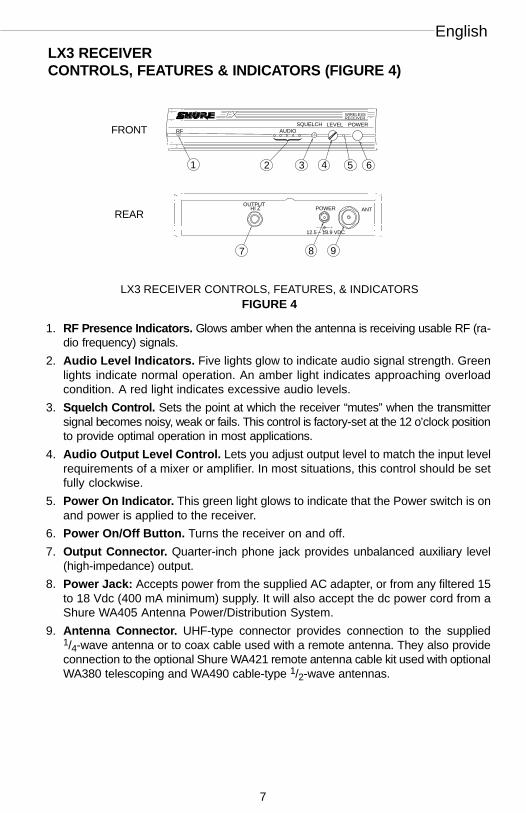
LX3 RECEIVER CONTROLS, FEATURES & INDICATORS (FIGURE 4)
ÑÑWIRELESSÑÑÑÑÑÑÑÑÑÑÑÑÑÑÑÑÑÑÑÑÑÑÑÑÑÑÑÑÑÑÑÑÑÑÑÑÑÑÑÑRECEIVERÑ ÑÑÑÑÑÑÑÑÑÑÑÑÑÑÑÑÑÑÑÑÑÑÑÑÑÑÑÑÑÑÑÑÑÑÑÑÑÑÑÑÑÑÑÑÑÑÑÑÑÑÑÑÑÑÑÑÑÑÑÑÑÑ
ÑÑÑÑÑÑÑÑÑÑÑÑÑÑÑÑÑ
ÑÑÑÑÑÑÑÑÑÑÑÑÑÑÑÑÑÑÑÑÑÑÑÑÑÑÑÑÑÑÑÑÑÑÑÑÑÑÑÑÑÑÑÑÑÑÑÑÑÑÑÑÑÑÑÑÑÑÑÑÑÑÑÑÑÑÑÑÑÑÑÑÑÑÑÑÑÑÑÑÑÑÑÑÑÑÑÑÑÑÑÑÑÑÑÑÑÑÑÑÑ
RF AUDIOSQUELCH LEVEL POWER
Ñ
ÑÑÑÑÑÑ
ÑÑÑÑÑÑÑÑÑÑÑÑÑÑ ÑÑÑÑÑÑÑÑÑÑÑ
ÑÑÑÑÑÑÑÑÑÑÑÑÑÑÑÑÑÑÑÑÑÑ
ÑÑÑÑÑÑÑÑÑ
ÑÑÑÑ
ÑÑÑANT
OUTPUTHI Z POWER
12.5 – 18.9 VDCÑÑÑÑÑÑ
ÑÑÑ
ÑÑÑÑ
ÑÑÑ
ÑÑÑÑÑÑ
1 2 3 4 5 6
7 8 9
REAR
FRONT
LX3 RECEIVER CONTROLS, FEATURES, & INDICATORSFIGURE 4
1. RF Presence Indicators. Glows amber when the antenna is receiving usable RF (ra-dio frequency) signals.
2. Audio Level Indicators. Five lights glow to indicate audio signal strength. Greenlights indicate normal operation. An amber light indicates approaching overloadcondition. A red light indicates excessive audio levels.
3. Squelch Control. Sets the point at which the receiver “mutes” when the transmittersignal becomes noisy, weak or fails. This control is factory-set at the 12 o’clock positionto provide optimal operation in most applications.
4. Audio Output Level Control. Lets you adjust output level to match the input levelrequirements of a mixer or amplifier. In most situations, this control should be setfully clockwise.
5. Power On Indicator. This green light glows to indicate that the Power switch is onand power is applied to the receiver.
6. Power On/Off Button. Turns the receiver on and off.
7. Output Connector. Quarter-inch phone jack provides unbalanced auxiliary level(high-impedance) output.
8. Power Jack: Accepts power from the supplied AC adapter, or from any filtered 15to 18 Vdc (400 mA minimum) supply. It will also accept the dc power cord from aShure WA405 Antenna Power/Distribution System.
9. Antenna Connector. UHF-type connector provides connection to the supplied1/4-wave antenna or to coax cable used with a remote antenna. They also provideconnection to the optional Shure WA421 remote antenna cable kit used with optionalWA380 telescoping and WA490 cable-type 1/2-wave antennas.
Wireless
8
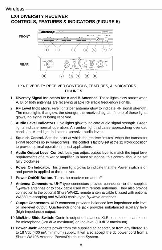
LX4 DIVERSITY RECEIVERCONTROLS, FEATURES & INDICATORS (FIGURE 5)
ÑÑÑÑÑÑÑÑÑÑÑÑÑ
12.5 – 18.9 VDC
ÑÑÑÑÑÑÑÑÑÑÑÑPOWERÑÑÑÑÑÑÑÑÑÑÑÑMARCAD
DIVERSITY
ÑÑÑÑÑÑÑÑÑÑÑÑÑÑÑÑÑÑÑÑÑÑÑÑÑÑÑÑÑÑÑÑÑÑÑÑÑÑÑÑÑÑÑÑÑÑÑÑÑÑÑÑÑÑÑÑÑÑÑÑÑ
ÑÑÑÑÑÑÑÑÑÑÑÑÑÑÑÑÑÑÑÑÑÑÑÑÑ
ÑÑÑÑÑÑÑÑÑÑÑÑÑÑÑÑÑÑÑ
ÑÑÑÑÑÑÑÑÑÑÑÑÑÑÑÑÑÑÑÑÑÑÑÑÑÑÑÑÑÑÑÑÑÑÑÑÑÑÑÑÑÑÑÑÑÑÑÑÑÑÑÑÑÑÑÑÑÑÑÑÑÑÑÑÑÑÑÑÑÑÑÑÑÑÑÑÑÑÑÑÑÑÑÑÑÑÑÑÑÑÑÑÑÑÑÑÑÑÑÑÑÑÑÑÑÑÑÑÑÑÑ
RF A RF B AUDIOSQUELCH LEVEL
ÑÑÑÑ
ÑÑÑ
ÑÑÑÑ
ÑÑÑÑÑÑÑÑ
ÑÑÑÑÑÑÑÑÑ ÑÑÑÑ
ÑÑÑÑÑÑÑ ÑÑÑÑÑÑÑÑÑÑÑÑ Ñ
ÑÑÑÑÑÑÑÑ
ÑÑÑÑÑÑÑ
ÑÑÑ
ÑÑÑÑ
ÑÑÑÑÑÑÑÑÑÑÑÑÑÑÑÑÑÑÑÑÑÑÑÑÑÑÑÑÑÑÑÑÑÑÑÑÑÑÑÑÑÑÑÑÑÑÑÑÑ
ÑÑÑÑÑÑÑÑÑÑÑÑ
ÑÑÑÑÑÑÑÑÑÑ
ÑÑÑÑ
ÑÑÑÑÑÑÑÑÑÑÑÑÑÑÑÑ
ANTANTOUTPUTS
HI Z BAL
MIC LINE
POWER
AB
LX4 DIVERSITY RECEIVER CONTROLS, FEATURES, & INDICATORSFIGURE 5
FRONT
REAR
1 2 3 4 5 6 7
8 9 10 9 11 8
1. Diversity Signal Indicators for A and B Antennas. These lights glow amber whenA, B, or both antennas are receiving usable RF (radio frequency) signals.
2. RF Level Indicators. Five lights per antenna glow to indicate RF signal strength.The more lights that glow, the stronger the received signal. If none of these lightsglows, no signal is being received.
3. Audio Level Indicators. Five lights glow to indicate audio signal strength. Greenlights indicate normal operation. An amber light indicates approaching overloadcondition. A red light indicates excessive audio levels.
4. Squelch Control. Sets the point at which the receiver “mutes” when the transmittersignal becomes noisy, weak or fails. This control is factory-set at the 12 o’clock positionto provide optimal operation in most applications.
5. Audio Output Level Control. Lets you adjust output level to match the input levelrequirements of a mixer or amplifier. In most situations, this control should be setfully clockwise.
6. Power On Indicator. This green light glows to indicate that the Power switch is onand power is applied to the receiver.
7. Power On/Off Button. Turns the receiver on and off.
8. Antenna Connectors. UHF-type connectors provide connection to the supplied1/4-wave antennas or to coax cable used with remote antennas. They also provideconnection to the optional Shure WA421 remote antenna cable kit used with optionalWA380 telescoping and WA490 cable–type 1/2-wave antennas.
9. Output Connectors. XLR connector provides balanced low-impedance mic levelor line-level output. Quarter-inch phone jack provides unbalanced auxiliary level(high-impedance) output.
10.Mic/Line Slide Switch: Controls output of balanced XLR connector. It can be setfor microphone (-20 dBV maximum) or line-level (+0 dBV maximum).
11.Power Jack: Accepts power from the supplied ac adapter, or from any filtered 15to 18 Vdc (400 mA minimum) supply. It will also accept the dc power cord from aShure WA405 Antenna Power/Distribution System.

English
9
RECEIVER MOUNTING
Single Rack–Mounted Receiver (Figure 6)If the receiver is to be located on a table or other horizontal surface, attach the four
adhesive bumpers to the bottom corners of the receiver. If the receiver is to be mountedin an audio equipment rack, identify the rack-mount kits supplied with your system andfollow the appropriate assembly directions below.
1. Remove two screws from each side of the receiver.
2. Position the large mounting brackets over the holes on the sides of the receiver andsecure them to the receiver with the screws removed in Step 1.
3. If you are not going to front mount the antennas with a Shure WA503 Front MountConversion Kit, insert the plastic plugs into the holes in the brackets.
4. Secure the assembly to a standard audio equipment rack with four screws.
SINGLE RACK–MOUNTED RECEIVERFIGURE 6
ÑÑ
ÑÑÑÑÑÑÑÑÑÑÑÑÑÑÑÑ
ÑÑÑÑÑÑÑÑÑÑÑÑÑÑ
ÑÑÑÑÑÑÑÑÑÑÑÑÑÑÑÑÑÑÑÑÑÑÑÑÑ
ÑÑÑÑÑÑÑÑÑÑÑÑÑÑÑÑÑÑ
ÑÑ
ÑÑÑÑÑÑÑÑÑÑ
ÑÑÑÑÑÑÑÑ
ÑÑÑÑÑ
ÑÑÑÑÑ
ÑÑÑÑÑÑÑÑÑÑÑÑÑ
ÑÑÑÑÑÑÑÑÑÑÑÑ
ÑÑÑÑÑÑÑÑÑ
ÑÑÑÑÑ
ÑÑÑÑÑÑÑÑÑÑÑÑÑÑÑ ÑÑÑÑ
ÑÑÑÑÑÑÑÑÑÑ
ÑÑÑÑÑÑÑÑÑÑÑÑÑÑÑÑÑÑÑÑÑÑÑÑÑÑÑÑÑÑÑÑÑÑÑÑÑÑÑÑÑÑÑÑÑÑÑÑÑÑÑÑÑÑÑÑÑÑÑÑÑÑÑÑÑÑÑÑÑ
ÑÑÑÑÑÑÑÑÑÑÑÑÑÑÑÑÑÑÑÑÑÑÑÑÑÑÑÑÑÑÑÑÑÑÑÑÑÑÑÑÑ ÑÑÑÑÑÑÑÑÑÑÑÑÑÑÑÑÑ
ÑÑÑÑÑÑÑÑÑÑÑÑÑÑÑÑÑÑÑÑÑÑÑÑÑÑÑÑÑ Ñ
Double Rack–Mounted Receivers (Figure 7)1. Remove the two screws on the outer side of each receiver.
2. Position the small mounting brackets over the holes on the outer side of each receiv-er, and secure them with the screws removed in Step 1.
3. Remove the screws on the inner side of each receiver.
4. Position two link bars over the holes and secure them with the screws removed inStep 3. For the receiver on the left, the link bar should be positioned so that itsthreaded hole is toward the front of the receiver. For the receiver on the right, thelink bar should be positioned so that its threaded hole is toward the rear of thereceiver.
5. Place the two receivers next to each other so that the threaded holes in the link barsline up, one on top of the other.
6. Fasten the receivers together by inserting a small screw from the top into the threadedhole at the front of the link bar. Then insert the other screw from the bottom into thethreaded hole at the rear of the link bar.
7. Secure the assembly to a standard audio equipment rack, using four screws.
ÑÑÑÑÑÑÑ
ÑÑÑÑÑÑÑÑÑ
ÑÑÑÑÑÑÑÑÑ
ÑÑÑÑÑÑÑ
ÑÑÑÑÑ
ÑÑÑÑÑÑ
ÑÑÑÑÑÑÑÑÑ
ÑÑÑÑÑÑÑÑÑ
ÑÑÑ
ÑÑÑÑÑÑÑÑÑÑÑÑÑÑÑÑ
ÑÑÑÑÑÑÑÑÑÑÑÑÑÑÑÑÑÑÑÑÑ
DOUBLE RACK–MOUNTED RECEIVERSFIGURE 7
ÑÑ
ÑÑÑÑÑÑÑÑÑÑÑÑÑÑÑ
ÑÑÑÑÑÑÑÑÑÑÑ
ÑÑÑÑÑÑÑÑÑÑÑÑÑÑÑÑÑÑÑÑÑÑÑÑÑÑÑÑÑÑÑÑÑÑÑÑÑÑÑÑÑÑÑÑÑÑÑÑÑÑÑÑÑÑÑÑ
ÑÑÑÑÑÑÑÑÑÑÑ
ÑÑÑÑÑÑÑÑÑÑÑÑÑÑÑÑÑÑÑÑÑ
ÑÑ
ÑÑÑÑÑÑÑÑÑÑÑ Ñ
ÑÑÑÑÑÑÑÑÑÑ
ÑÑÑÑÑÑÑÑ
ÑÑÑÑÑÑÑÑÑÑÑÑÑÑÑÑÑÑÑ
ÑÑÑÑÑÑÑÑÑÑÑÑÑÑÑÑ
ÑÑÑÑÑÑÑÑÑÑÑÑÑ
ÑLINK BARS
ÑÑÑÑÑÑÑÑÑÑÑÑÑÑÑÑÑÑÑÑÑÑÑÑÑÑÑÑÑÑÑÑÑÑÑÑÑÑÑÑÑÑÑÑÑÑÑÑÑÑÑÑÑÑÑÑÑ
ÑÑÑÑ
ÑÑÑÑÑÑÑ
ÑÑÑÑÑÑÑÑÑÑÑÑÑÑÑÑÑÑÑÑÑÑÑÑÑÑÑÑÑÑÑÑÑÑ
ÑÑÑÑ ÑÑÑÑÑÑÑÑÑÑÑÑÑÑÑÑÑÑÑÑÑÑÑÑÑÑÑÑÑÑÑÑÑÑÑÑÑÑÑÑÑÑÑÑÑ Ñ ÑÑÑÑÑÑÑÑÑÑÑÑÑÑ
ÑÑÑÑÑÑÑÑÑÑÑÑÑÑÑÑÑÑÑÑÑ
ÑÑÑÑ
ÑÑÑÑÑÑÑ
ÑÑÑÑÑÑÑÑÑÑÑÑÑÑÑÑÑÑÑÑÑÑÑÑÑÑÑ
ÑÑÑÑÑÑÑÑÑ ÑÑÑÑÑÑÑÑÑÑÑÑÑÑÑÑÑÑÑÑÑÑÑÑÑÑÑÑÑÑÑÑÑÑÑÑÑÑÑÑÑÑÑÑÑ Ñ

Wireless
10
RECEIVER CONNECTIONS (FIGURE 8)
1. Attach the supplied quarter-wave antenna(s) to the antenna connector(s) on the receiv-er back panel. For best performance, the LX4 receiver antennas should be orientedwith the tips pointing away from each other at a 45° angle from vertical. The LX3 receiv-er antenna should be vertical.
2. Connect the receiver output to the mixer or amplifier input, using a standard audiocable with a female 3-pin XLR connector or 1/4-inch phone plug.
3. Connect the ac adapter to the POWER jack on the rear panel of the receiver.
4. Plug the ac adapter into an appropriate ac power source.
ÑÑÑÑ
ÑÑÑÑÑÑÑÑÑÑÑÑÑÑÑ
ÑÑ ÑÑÑÑÑÑÑÑ
ÑÑÑÑÑÑÑÑÑ
ÑÑÑÑÑÑÑÑÑÑÑÑÑÑÑÑÑÑÑÑÑÑÑÑÑÑÑÑÑÑÑÑÑÑÑÑÑÑÑÑÑÑÑÑÑÑÑÑÑÑÑÑÑÑÑÑ
ÑÑÑÑÑÑÑÑÑÑÑÑÑÑÑÑÑÑÑÑÑ
ÑÑÑÑÑÑÑÑÑÑÑÑ
ÑÑÑÑÑÑÑÑÑ ÑÑÑÑÑÑÑÑÑÑÑÑÑÑÑÑÑÑÑÑÑÑÑÑÑÑÑÑÑÑÑÑÑÑÑÑÑÑÑÑÑÑÑÑÑÑ
ÑÑÑÑÑÑÑÑÑÑÑÑÑÑÑÑÑÑÑÑÑÑÑÑÑÑ
ÑÑÑÑÑÑÑÑÑÑÑÑÑÑÑÑÑÑÑÑÑÑÑÑÑÑÑÑÑÑÑÑÑ
ÑÑÑÑÑÑÑÑÑÑÑ
ÑÑÑÑÑÑÑÑ
ÑÑÑÑÑÑÑÑÑÑÑÑÑÑÑÑÑÑÑÑÑÑÑÑÑÑ ÑÑÑÑÑÑÑÑÑÑÑÑÑÑÑÑÑÑÑÑÑÑÑÑÑÑÑÑÑÑÑÑÑÑÑÑÑÑÑÑÑÑÑÑÑÑÑÑ
ÑÑ
ÑÑÑ
ÑÑÑÑÑÑÑÑÑÑ
Ñ
ÑÑÑÑÑÑLX4ÑÑ
Ñ
45° 45°
LX4 ÑWIRELESS
ÑÑÑÑÑÑÑÑÑÑÑÑÑÑÑÑÑÑÑÑÑÑÑÑÑRECEIVER
Ñ ÑÑÑÑÑÑÑÑÑÑÑÑÑÑÑÑÑÑÑÑÑÑÑÑÑÑÑÑÑÑÑÑÑÑÑÑ
ÑÑÑÑÑÑÑÑÑ
ÑÑÑÑÑÑÑÑÑÑÑÑÑÑÑÑÑÑÑÑÑÑÑÑÑÑÑÑÑÑÑÑÑÑÑÑ
ÑÑÑÑÑÑÑÑÑÑÑÑÑÑÑÑÑÑÑÑÑÑÑÑÑÑÑÑÑÑÑÑÑÑÑÑÑÑÑÑÑÑÑÑ
1
RF AUDIOSQUELCH LEVEL POWER
3 42 5 6
ÑÑÑÑÑÑÑÑÑÑÑÑÑÑÑÑÑÑ ÑÑÑÑÑÑÑÑÑÑÑÑÑÑÑÑÑÑÑÑÑÑÑÑÑÑÑÑ
Ñ
ÑÑÑ
ÑÑÑÑ
ANTOUTPUT
HI Z POWER
12.5 – 18.9 VDCÑÑÑÑÑÑÑ Ñ
ÑÑÑÑÑÑÑÑÑ
ÑÑÑÑÑÑÑÑÑÑÑÑÑÑÑÑÑÑÑÑÑÑÑÑÑÑÑÑÑÑÑÑÑÑÑ
ÑÑ
LX3
LX3
AUDIO MIXER
AUDIO MIXER
RECEIVER CONNECTIONSFIGURE 8
NOTE: If the receiver is rack-mounted, the antenna(s) must extend above the rack cabinetor be remotely located.
Improved LX4 diversity performance may be obtained by installing one or both anten-na(s) at a remote location and separating them by 1.5 meters (60 inches) or more.Shure WA380 telescoping or WA490 cable-type 1/2-wave antennas are recommendedfor remote location, and they should be connected to the receiver via WA421 ExtensionCable Kit(s) or other suitable low-loss cable.
English
11
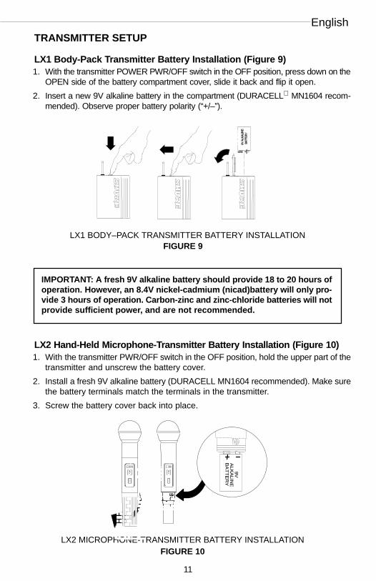
TRANSMITTER SETUP
LX1 Body-Pack Transmitter Battery Installation (Figure 9)1. With the transmitter POWER PWR/OFF switch in the OFF position, press down on the
OPEN side of the battery compartment cover, slide it back and flip it open.
2. Insert a new 9V alkaline battery in the compartment (DURACELL MN1604 recom-mended). Observe proper battery polarity (“+/–”).
ÑÑÑ
ÑÑÑ
ÑÑÑ
ÑÑÑ
ÑÑÑ
ÑÑÑÑÑÑ
Ñ
ÑÑFIGURE 9LX1 BODY–PACK TRANSMITTER BATTERY INSTALLATION
ÑÑÑ
ÑÑÑ
ÑÑÑ
ÑÑÑÑ
ÑÑÑÑ
ÑÑÑÑ
ÑÑÑÑ
ÑÑÑÑ
ÑÑÑÑÑÑÑÑÑÑ
ÑÑÑÑ
ÑÑÑÑ
ÑÑÑÑ
ÑÑÑÑ
ÑÑÑÑ
ÑÑÑÑ
ÑÑÑÑ
ÑÑÑÑÑÑÑÑÑÑÑ
ÑÑÑÑ
ÑÑÑÑ
IMPORTANT: A fresh 9V alkaline battery should provide 18 to 20 hours ofoperation. However, an 8.4V nickel-cadmium (nicad)battery will only pro-vide 3 hours of operation. Carbon-zinc and zinc-chloride batteries will notprovide sufficient power, and are not recommended.
LX2 Hand-Held Microphone-Transmitter Battery Installation (Figure 10)1. With the transmitter PWR/OFF switch in the OFF position, hold the upper part of the
transmitter and unscrew the battery cover.
2. Install a fresh 9V alkaline battery (DURACELL MN1604 recommended). Make surethe battery terminals match the terminals in the transmitter.
3. Screw the battery cover back into place.
ÑÑ
ÑÑÑÑÑÑÑ
ÑÑÑÑ
LX2 MICROPHONE-TRANSMITTER BATTERY INSTALLATIONFIGURE 10
ÑÑÑÑÑÑÑÑÑÑÑÑÑÑÑÑÑÑÑÑ
ÑÑÑÑÑ
ÑÑÑÑÑ
ÑÑÑ
ÑÑÑ
ÑÑÑ
ÑÑÑ
ÑÑÑ
ÑÑÑ
ÑÑÑ
ÑÑÑ
ÑÑÑ
ÑÑÑ
ÑÑÑ
ÑÑÑÑÑÑÑÑÑÑÑÑÑÑÑÑÑÑÑÑÑÑÑÑÑÑÑÑÑ
ÑÑÑ
ÑÑÑ
ÑÑÑ
Ñ ÑÑÑÑÑÑÑ
ÑÑ
ÑÑÑÑÑÑÑ
Ñ
ÑÑÑÑÑÑÑÑÑÑÑÑÑÑÑÑÑÑÑÑÑÑÑ
ÑÑÑÑÑÑÑÑÑÑÑÑÑÑÑ
ÑÑÑ
ÑÑÑÑÑÑÑÑÑÑÑÑÑÑÑÑÑÑÑÑÑÑÑÑÑ
ÑÑÑ
ÑÑÑÑÑÑÑÑÑÑÑÑÑÑÑÑÑÑÑÑÑ
ÑÑÑÑ
ÑÑÑÑÑÑÑÑÑÑÑÑÑÑÑÑÑÑÑÑÑÑÑÑÑÑÑÑÑÑÑÑÑÑÑ
ÑÑÑ
ÑÑÑÑÑÑÑÑÑÑÑÑÑÑÑÑÑÑÑÑÑÑÑ
ÑÑÑ
ÑÑÑÑÑÑÑÑÑÑÑÑÑÑÑÑÑÑ
ÑÑÑÑ
ÑÑÑÑÑÑÑ
ÑÑÑÑÑÑÑÑÑÑÑÑÑÑÑÑ

Wireless
12
Checking the Transmitter BatteryTurn the transmitter PWR/OFF switch to the PWR position and observe that one or
two of the three lights on the transmitter glows. The amount of battery life remaining willbe indicated by the color of the light(s), as shown in the following table.
Battery Life Indicators Remaining TransmitterOperating Time*
Green 6 to 20 hours
Green and Amber 4 to 6 hours
Amber 2 to 4 hours
Red 1 hour or less
* Estimated operating time assumes the use of a fresh 9 V alkaline battery (Duracell MN1604).
NOTE: A rechargeable 8.4V nicad battery causes the indicators to change more quick-ly than if using a 9V alkaline battery. Actual times depend on the type and brand of bat-tery used.
Connecting a Microphone or Instrument Cable to the LX1(Figure 11)1. Connect the microphone cable or instrument cable to the transmitter input jack.
2. Install the microphone by attaching it to the user’s tie, shirt, or collar (lavalier mic),placing it over the user’s head (headset mic), or affixing it to an acoustic musicalinstrument (instrument mic).
3. If using an instrument adapter cable, attach the other end of the instrument cableto the instrument output connector.
MICROPHONE CABLE OR WA302 INSTRUMENT ADAPTER
CABLE
LX1 BODY-PACK TRANSMITTER CABLE CONNECTION
FIGURE 11
Ñ
ÑÑÑÑÑÑÑÑÑÑÑÑÑÑÑÑÑÑÑÑÑÑÑÑÑ
ÑÑÑÑÑÑÑÑÑÑÑÑ
ÑÑÑÑÑÑÑÑÑÑÑÑ
ÑÑÑÑÑÑÑÑÑÑÑÑ
ÑÑÑÑÑÑÑÑÑÑÑÑ
ÑÑÑÑÑÑÑÑÑÑÑÑ
ÑÑÑÑÑÑÑÑÑÑÑÑ
ÑÑÑÑÑ
ÑÑÑ
Ñ
ÑÑÑÑÑÑÑÑÑÑÑÑÑÑ
ÑÑÑÑÑÑÑÑÑÑÑÑ
ÑÑÑÑÑÑÑÑÑÑÑÑÑÑÑÑÑÑ
ÑÑÑÑÑÑÑÑÑÑÑÑÑÑ
ÑÑÑÑÑÑÑÑÑÑÑÑÑÑ
ÑÑÑÑÑÑÑÑÑÑÑÑÑÑÑÑÑÑÑÑÑÑÑÑÑÑÑÑÑÑÑ
ÑÑÑÑÑÑÑÑÑÑÑÑÑÑÑÑÑÑÑÑÑÑÑÑÑÑÑÑÑ
ÑÑÑÑÑÑ
ÑÑÑÑÑÑÑÑÑÑÑÑÑÑÑ
ÑÑÑÑÑÑÑÑÑÑÑÑÑÑÑÑÑÑÑÑÑÑÑÑÑÑÑÑÑÑÑÑÑÑÑÑÑÑÑÑÑÑ
ÑÑÑÑÑÑÑÑÑÑÑÑÑÑÑÑÑÑÑÑÑÑÑÑÑÑÑÑÑÑÑÑÑÑÑÑÑÑÑÑÑÑÑÑÑ
ÑÑÑÑÑÑÑÑÑ
Ñ
ÑÑÑÑÑÑÑÑÑÑÑ
English
13
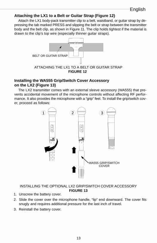
Attaching the LX1 to a Belt or Guitar Strap (Figure 12)Attach the LX1 body-pack transmitter clip to a belt, waistband, or guitar strap by de-
pressing the tab marked PRESS and slipping the belt or strap between the transmitterbody and the belt clip, as shown in Figure 11. The clip holds tightest if the material isdrawn to the clip’s top wire (especially thinner guitar straps).
ÑÑ
Ñ
ÑÑ ÑÑ
ÑÑÑ
ÑÑBELT OR GUITAR STRAP
ATTACHING THE LX1 TO A BELT OR GUITAR STRAPFIGURE 12
ÑÑÑÑ
Installing the WA555 Grip/Switch Cover Accessoryon the LX2 (Figure 13)
The LX2 transmitter comes with an external sleeve accessory (WA555) that pre-vents accidental movement of the microphone controls without affecting RF perfor-mance. It also provides the microphone with a “grip” feel. To install the grip/switch cov-er, proceed as follows:
WA555 GRIP/SWITCHCOVER
ÑÑÑÑ
ÑÑÑÑÑÑÑÑÑÑÑÑÑÑÑÑÑÑÑÑÑÑÑÑÑÑ
ÑÑ
ÑÑÑÑÑÑÑÑ
ÑÑ
ÑÑÑÑÑÑÑÑÑÑÑÑÑÑÑÑÑÑÑÑ
Ñ
ÑÑÑÑÑÑÑ Ñ
ÑÑÑ
ÑÑÑ
ÑÑÑÑÑÑÑÑÑÑÑÑÑÑÑÑÑÑÑÑÑÑÑÑÑÑÑÑÑÑÑÑÑÑÑÑÑÑÑÑ
ÑÑ
ÑÑÑ
ÑÑÑ
ÑÑÑ
ÑÑÑ
ÑÑÑ
ÑÑÑ
ÑÑÑ
ÑÑÑ
ÑÑÑ
ÑÑÑ
ÑÑÑ
ÑÑÑÑÑÑÑÑÑÑÑÑÑÑÑÑÑÑÑÑÑÑÑÑÑÑ
ÑÑÑ
ÑÑÑ
ÑÑ
ÑÑ
ÑÑÑÑ
ÑÑ
ÑÑÑÑÑÑÑÑ
ÑÑÑÑÑÑ
ÑÑÑÑÑÑÑÑÑÑÑÑÑÑÑÑÑ
ÑÑÑÑÑ
ÑÑ
ÑÑÑÑÑÑÑÑ
ÑÑÑ
ÑÑÑ
ÑÑÑ
ÑÑÑ
ÑÑÑ
ÑÑÑ
ÑÑÑ
ÑÑÑ
ÑÑÑ
ÑÑÑ
ÑÑÑ
ÑÑÑÑÑÑÑÑÑÑ
ÑÑÑÑÑÑÑÑÑÑÑÑÑÑÑÑÑ
ÑÑÑ
ÑÑÑ
ÑÑ
ÑÑÑ
ÑÑÑÑÑÑÑÑÑÑÑÑÑÑÑÑÑÑÑÑÑÑÑÑÑÑ
ÑÑÑÑÑÑÑÑÑÑÑÑÑÑÑÑÑÑÑÑÑÑÑÑÑÑÑÑÑÑÑÑ
Ñ
ÑÑÑÑÑÑÑ
ÑÑÑÑÑÑÑÑÑÑÑÑÑÑÑÑÑÑÑÑÑÑÑÑÑÑÑÑÑÑÑÑÑÑÑÑÑÑÑÑ
ÑÑÑ
ÑÑÑ
ÑÑÑ
ÑÑÑ
ÑÑÑ
ÑÑÑ
ÑÑÑ
ÑÑÑ
ÑÑÑ
ÑÑÑ
ÑÑÑ
ÑÑÑ
ÑÑÑÑÑÑÑÑÑÑÑÑÑÑÑÑÑÑÑÑÑÑÑÑÑÑÑ
ÑÑÑ
ÑÑÑ
ÑÑ
ÑÑÑÑ
INSTALLING THE OPTIONAL LX2 GRIP/SWITCH COVER ACCESSORYFIGURE 13
ÑÑÑÑÑÑÑÑÑÑÑÑÑÑÑÑÑÑÑÑÑÑÑ ÑÑÑ
ÑÑÑÑÑÑÑÑÑÑÑÑÑÑÑÑÑÑÑÑÑÑÑÑÑ
1 2 3
1. Unscrew the battery cover.
2. Slide the cover over the microphone handle, “lip” end downward. The cover fitssnugly and requires additional pressure for the last inch of travel.
3. Reinstall the battery cover.

Wireless
14
LX1 BODY–PACK SYSTEM SETUP AND OPERATIONFIGURE 14
RECEIVER
ÑÑÑÑÑÑÑÑÑÑÑÑÑÑÑÑÑÑÑÑÑÑÑÑÑÑÑÑÑÑÑÑÑÑÑÑÑÑÑÑÑÑÑÑÑÑÑÑÑÑÑÑ
WM98 MIC& A98KCS
HORN MOUNT
WH20HEADSET
WA302 INSTRUMENTADAPTER CABLE
LAVALIERMIC
Á
OPERATING LX1 BODY–PACK SYSTEMS (FIGURE 14)
1. Clip the LX1 body pack transmitter to your belt, waistband, or guitar strap.
2. Connect the lavalier microphone, headset or instrument adapter cable to the body–pack transmitter.
3. If you are using a lavalier microphone, clip the mic to your tie, lapel, or other gar-ment. If you are using a headset, put the headset on. If you are using a Shure WM98microphone, insert it into an A98KCS horn mount and clamp it to your horn. If youare using an instrument adapter cable, plug the cable into the instrument.
4. Slide the transmitter PWR/OFF switch to the PWR position. One of the three lightson the transmitter illuminates.
5. Press the POWER button on the receiver. The green “power on” light on the receiverand the RF light(s) illuminates.
6. Slide the transmitter ON/MUTE switch to the ON position and begin speaking orplaying your instrument.
NOTE: If the red PEAK light on the receiver does not flicker during the loudest sounds,the transmitter gain may need to be increased. Refer to the Adjusting the TransmitterAudio Gain Level section. Then, if the system is still not operating properly, consult theTroubleshooting table.
7. During the performance or presentation, slide the ON/MUTE switch to the MUTEposition when the system is not in use.
8. When the performance or presentation is over, slide the transmitter PWR/OFFswitch to the OFF position to conserve battery power.
English
15
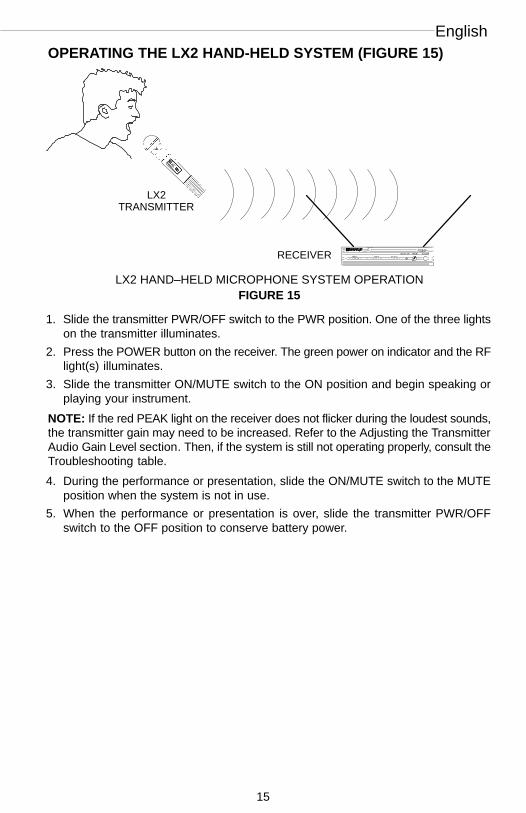
OPERATING THE LX2 HAND-HELD SYSTEM (FIGURE 15)
LX2TRANSMITTER
ÑÑÑÑÑÑÑÑÑÑÑÑÑÑÑÑÑÑÑÑ
ÑÑÑÑÑÑ
ÑÑÑÑÑÑÑÑÑÑÑÑÑÑÑÑÑÑÑÑÑÑÑÑÑÑÑÑÑÑÑÑÑÑÑÑÑÑÑÑÑÑÑÑÑÑÑÑ
ÑÑÑÑÑÑÑÑÑÑÑÑÑÑÑÑÑÑÑÑÑÑÑÑÑÑÑÑÑÑÑÑÑÑÑ
ÑÑÑÑÑÑÑÑÑÑÑÑÑÑÑÑÑÑÑÑÑÑÑÑÑÑÑÑÑÑÑÑÑÑÑÑÑÑÑÑÑÑÑÑÑÑÑÑÑÑÑÑÑÑÑÑÑÑÑÑÑÑÑÑÑÑÑÑÑÑÑÑÑÑÑÑÑÑÑÑÑÑÑÑÑÑÑÑÑÑÑÑÑÑÑÑÑ ÑÑÑÑÑÑÑÑÑÑÑÑÑÑÑÑÑÑÑÑÑÑÑÑÑÑÑÑÑÑÑÑÑÑÑÑÑÑÑÑ ÑÑRECEIVER
ÑÑÑÑÑÑÑÑÑÑÑÑÑÑÑÑÑÑÑÑÑÑÑÑÑÑÑÑÑÑÑÑÑÑÑÑÑÑÑÑÑÑÑÑÑÑÑÑÑÑÑÑÑÑÑÑÑÑÑÑÑÑÑÑÑÑÑÑÑÑ
LX2 HAND–HELD MICROPHONE SYSTEM OPERATIONFIGURE 15
1. Slide the transmitter PWR/OFF switch to the PWR position. One of the three lightson the transmitter illuminates.
2. Press the POWER button on the receiver. The green power on indicator and the RFlight(s) illuminates.
3. Slide the transmitter ON/MUTE switch to the ON position and begin speaking orplaying your instrument.
NOTE: If the red PEAK light on the receiver does not flicker during the loudest sounds,the transmitter gain may need to be increased. Refer to the Adjusting the TransmitterAudio Gain Level section. Then, if the system is still not operating properly, consult theTroubleshooting table.
4. During the performance or presentation, slide the ON/MUTE switch to the MUTEposition when the system is not in use.
5. When the performance or presentation is over, slide the transmitter PWR/OFFswitch to the OFF position to conserve battery power.

Wireless
16
GAIN AND SQUELCH ADJUSTMENT
Adjusting the Transmitter Audio Gain Level (Figure 16)The transmitter audio gain level has been factory pre-set to provide satisfactory out-
put in most applications. However, for loud singers or high-output musical instruments,the preset level may be too high, as indicated by the constant glow of the red light onthe receiver audio level meter. Soft-spoken talkers or singers may find that the factorysetting is too low, as indicated by the failure of the amber audio level light to light at all.
To adjust the audio gain, locate the transmitter audio gain control and use the sup-plied screwdriver to adjust the control.
• For high sound pressure level applications, such as loud singing, decrease the au-dio gain level by rotating the gain control counterclockwise (while the vocalist is sing-ing or the musical instrument is being played) until the red audio level light on the re-ceiver flickers occasionally.
• For low sound pressure level applications, such as soft–spoken talkers, increasethe audio gain level by rotating the gain control clockwise (while the vocalist is sing-ing or the musical instrument is being played) until the red audio level light on thereceiver flickers occasionally.
NOTE: If using the WH20TQG headset, you must increase the gain level to the fullclockwise position. Then, if necessary, rotate the control back slightly.
FIGURE 16
LX1
INCREASE GAIN
DECREASEGAIN
ÑÑÑÑ
ÑÑÑÑ
ÑÑÑÑ
ÑÑÑÑ
ÑÑÑÑ
LX2 ÑÑÑÑÑ
ÑÑÑÑÑÑÑÑÑÑÑÑÑÑÑÑÑÑÑÑ
ÑÑÑÑÑ
ÑÑÑÑÑÑÑÑÑ
ÑÑÑÑÑÑÑÑÑÑÑÑÑÑÑÑÑÑÑÑÑÑÑÑÑÑÑÑÑÑÑÑÑÑÑÑÑÑÑÑÑÑÑÑÑÑÑÑÑÑÑÑÑÑ
ÑÑÑÑÑÑÑ
ÑÑÑÑÑÑÑ
ÑÑÑÑÑÑÑÑÑÑÑÑÑÑ
ÑÑÑÑ
ÑÑÑÑ
ÑÑÑÑ
ÑÑÑÑ
ÑÑÑÑ
ÑÑÑÑ
ÑÑÑÑ
ÑÑÑÑ
ÑÑÑÑ
ÑÑÑÑ
INCREASEGAIN
DECREASE GAIN
TRANSMITTER AUDIO GAIN LEVEL ADJUSTMENT

English
17
Adjusting the Receiver Squelch Control (Figure 17)The receiver squelch control is factory preset at the 12 o’clock position for op-
timum performance. No further adjustment is normally required. However, it ispossible to adjust the squelch control to emphasize either signal quality or systemrange.
• To raise the squelch threshold, rotate the control clockwise. This causes the receiverto demand a higher quality signal (less noise before muting), but it reduces the operatingrange.
• To lower the squelch threshold, rotate the control counterclockwise. This allows alower quality signal through (more noise before muting), but it extends the operatingrange.
DECREASESQUELCH
INCREASESQUELCH
ÑÑÑÑÑÑÑÑÑÑÑÑÑÑÑÑÑÑÑÑÑÑÑÑÑÑÑÑÑÑÑÑÑÑÑÑÑÑÑÑÑÑÑÑ
ÑÑÑÑÑÑÑÑÑÑÑÑÑÑÑÑÑÑÑÑÑÑÑÑÑÑÑÑÑÑÑÑÑÑÑÑÑÑÑÑÑÑÑÑÑÑÑÑÑÑÑÑÑÑÑ
ÑÑÑÑÑÑÑÑÑÑÑÑÑÑÑÑÑÑ
ÑÑÑÑÑÑÑÑÑÑÑÑÑÑÑÑÑÑÑÑÑÑÑÑÑÑÑÑÑÑÑÑÑÑÑÑÑÑÑÑÑÑÑÑÑÑÑ
ÑÑÑÑÑÑÑÑÑÑÑÑ
ÑÑÑÑÑÑÑÑÑÑÑÑÑÑÑÑÑÑÑÑÑÑÑÑÑÑÑÑÑÑÑÑÑÑÑÑÑÑÑÑÑÑÑÑÑÑ
ÑÑWIRELESSÑÑÑÑÑÑÑÑÑÑÑÑÑÑÑÑÑÑÑÑÑÑÑÑÑÑÑÑÑÑÑÑÑÑÑÑÑÑRECEIVERÑ ÑÑÑÑÑÑÑÑÑÑÑÑÑÑÑÑÑÑÑÑÑÑÑÑÑÑÑÑÑÑÑÑÑÑÑÑÑÑÑÑÑÑÑÑÑÑÑÑÑÑÑÑÑÑÑÑÑÑÑÑÑÑ
ÑÑÑÑÑÑÑÑÑÑÑÑÑÑÑÑÑ
ÑÑÑÑÑÑÑÑÑÑÑÑÑÑÑÑÑÑÑÑÑÑÑÑÑÑÑÑÑÑÑÑÑÑÑÑÑÑÑÑÑÑÑÑÑÑÑÑÑÑÑÑÑÑÑÑÑÑÑÑÑÑÑÑÑÑÑÑÑÑÑÑÑÑÑÑÑÑÑÑÑÑÑÑÑÑÑÑÑÑÑ
ÑÑÑÑÑÑÑÑÑÑÑ
RF AUDIO
SQUELCH LEVEL POWER
LX4 LX3DECREASESQUELCH
INCREASESQUELCH
RECEIVER SQUELCH CONTROL ADJUSTMENTFIGURE 17
TIPS FOR ACHIEVING OPTIMUM PERFORMANCE
• Maintain a line-of-sight between the transmitter and receiver antennas, if possible.Avoid placing transmitter and receiver where metal or other dense materials maybe present.
• Avoid placing the receiver near computers or other RF generating equipment.
• Avoid placing the receiver in the bottom of an equipment rack unless the antennasare remotely located.
• Use the proper receiver antenna(s). A 1/4-wave antenna can be used if it is mounteddirectly on the receiver; use a 1/2-wave or other ground-plane-dependent antennaif antennas are remotely located. Use the Shure WA503 Front-Mount Antenna Con-version Kit to mount antennas on the front of the receiver.
• Mount 1/4-wave antennas with the antenna tips pointed away from each other at a45° angle, and away from large metal objects.
• Use the proper antenna cable when remotely locating receiver antennas. For best per-formance, use the Shure WA421 50 Ω RG-58 coaxial antenna cable, and the minimumlength necessary. For cable runs greater than 12.2 meters (40 feet), use RG–8 coaxialcable.
• Mount diversity antennas at least 1/4-wave apart [42 cm (17 inches) for VHF systems,although a 1.5 m (60 inches) spacing is preferred]. For multiple system installations,use the Shure WA405 Antenna/Power Distribution Kit or the WA470 Passive AntennaSplitter to minimize the number of antennas and reduce interference.
• Use the Shure WA302 Instrument Cable when using the LX1 transmitter with a musi-cal instrument.
• If using multiple wireless systems, maintain a distance of at least 3 meters (10 ft.)between the transmitter and the closest receiving antenna.

Wireless
18
TROUBLESHOOTING
The table below identifies some common problems and their solutions. If unable tosolve a problem, contact your dealer or the Shure Service Department at 847-866-5733(7:30 am to 4:00 pm CST). In Europe, call 49-7131-72140; other international users callShure in the U.S.A. at 847-866-2200.
Problem Solution
No sound; receiver RF light(s) andAUDIO lights not glowing.
Make sure POWER switches on transmitterand receiver are on.Check transmitter Power/Battery FuelGauge to ensure that battery is providingpower. Replace battery if necessary.Check receiver squelch setting.Check receiver antenna connection(s).Make sure at least one antenna is in the lineof sight of the transmitter. If necessary, re-duce the distance between transmitter andreceiver.
No receiver sound; RF and Audio Level me-ter lights glowing.
Turn up the receiver audio output LEVEL con-trol.Check for proper connection between re-ceiver and microphone mixer.Talk into the microphone and observe thereceiver audio level lights. If they glow, theproblem is elsewhere in the sound system.
Received signal is noisy or containsextraneous sounds with transmitter on.
Check Power/Battery Fuel Gauge and re-place battery if power is low.Remove local sources of RF interference,such as lighting equipment.If using a guitar or other instrument, makesure it is connected to the LX1 with a ShureWA302 adapter cable.Two transmitters may be operating on thesame frequency. Locate and turn one off.Signal may be too weak. Reposition anten-nas. If possible, move them closer to thetransmitter.Adjust receiver squelch control.
Noise from receiver with transmitter off. Adjust receiver squelch control.Remove local sources of RF interference,such as lighting equipment.Reposition the receiver or antennas.
Momentary loss of sound as transmitter ismoved around performing area.
Reposition receiver and perform another“walkthrough” test and observe the RF levelor Diversity signal indicators. If audio drop-outs persist, mark these “dead spots” in theperforming area and avoid them during theperformance.

English
19
SPECIFICATIONSRF Carrier Frequency Range
169.445 to 240.000 MHz (available frequencies depend on the applicable regulations in thecountry where the system is used)
Working Range91 m (300 ft) under typical conditions. NOTE: Actual working range depends on RF signal
absorption, reflection and interference.Audio Frequency Response
50 to 15,000 Hz, ±2 dB. NOTE: Overall system frequency response depends on the micro-phone element.
Audio Output Level (±15 kHz deviation, 1 kHz tone)XLR connector (into 600 Ω load): 0 dBV (line), –20 dBV (mic)1/4 inch connector (into 3 kΩ load): –8.8 dBV
Gain Adjustment RangeLX1: 40 dBLX2: 25 dB
ImpedancesLX1 (input): 1 MΩLX3 (output): 3 kΩ (1/4-inch phone jack)LX4 (output): 150 Ω (XLR); 3 kΩ (1/4-inch phone jack)
Modulation±15 kHz deviation compressor-expander system with pre- and de-emphasis
RF Power OutputLX1, LX2: 50 mW maximum (complies with FCC and IC regulations)
Dynamic Range>102 dB, A-weighted
RF Sensitivity0.45 µV for 12 dB SINAD (typical)
Image Rejection80 dB typical
Spurious Rejection75 dB typical
Ultimate Quieting (ref. 15 kHz deviation)>100 dB, A-weighted
Audio PolarityPositive pressure on microphone diaphragm (or positive voltage applied to tip of WA302phone plug) produces positive voltage on pin 2 with respect to pin 3 of low impedance outputand the tip of the high impedance 1/4-inch output.
System Distortion (ref. ±15 kHz deviation, 1 kHz modulation)0.3% THD typical
Power RequirementsLX1, LX2: 9V alkaline battery (Duracell MN1604 recommended); 8.4V Nicad optionalLX3, LX4: 12.5 - 18 Vdc (negative ground), 400 mA
Battery Life18 to 20 hours (with Duracell MN1604 9V alkaline battery)
Operating Temperature Range-20° to 50° C (–4° to 122° F). NOTE: Battery characteristics may limit this range.
Overall DimensionsLX1: 83 mm H x 64 mm W x 26 mm D (31/4 x 21/2 x 11/32 in.)LX2/58, LX2/BETA 58: 241 mm L x 51 mm Dia. (91/2 x 2 in.)LX2/87, LX2/BETA 87: 216 mm L x 51 mm Dia. (81/2 x 2 in.)LX3, LX4: 43 mm H x 214 mm W x 183 mm D (111/16 x 87/16 x 73/16 in.)

Wireless
20
Net WeightLX1: 79 g (2.8 oz.) without batteryLX2/58, LX2/BETA 58: 295 g (10.4 oz.) without batteryLX2/87, LX2/BETA 87: 193 g (6.8 oz.) without batteryLX3: 1,049 g (2 lbs, 5 oz.)LX4: 1,105 g (2 lbs, 7 oz.)
CERTIFICATIONLX1,LX2 Transmitters: Type Accepted under FCC Parts 74 and 90. Certified by IC in Can-
ada under TRC-78.LX3, LX4 Receivers: Approved under the Notification provision of FCC Part 15. Certified
by IC in Canada under TRC-78.LX1, LX2, LX3, LX4: RA Type Approved to MPT 1345, MPT 1350, ETS 300 422. BZT Type
Approved to FTZ 17TR 2019, BAPT 122 R1.Meets Requirements of EMC Standard EN 301 489 Parts 1 and 9. Meets Low VoltageDirective. LX Systems are eligible to carry the CE marking.
Shure Models LX1 and LX2 Transmitters meet the essential requirements of theEuropean R&TTE Directive 99/5/EC and are eligible to carry the CE marking.
O682Shure Models LX3 and LX4 Receivers meet the essential requirements of the European
R&TTE Directive 99/5/EC and are eligible to carry the CE marking.Power supply meets the following safety standard:
PS40 Power Supply: UL 1310, CAN/CSA 22.2 No. 223.PS40E Power Supply: EN 60950PS40UK Power Supply: EN 60950
FURNISHED ACCESSORIESMicrophone Stand Adapter (LX2) WA370A. . . . . . . . . . . . . . . . . . . . . . . . . . . . . . . . . . . . . . Single Receiver HR Rack Panel Kit WA500. . . . . . . . . . . . . . . . . . . . . . . . . . . . . . . . . . . . . Dual Receiver (Side–by–Side) HR Rack Panel Kit (LX4) WA502. . . . . . . . . . . . . . . . . . . Grip/Switch Cover (LX2) WA555. . . . . . . . . . . . . . . . . . . . . . . . . . . . . . . . . . . . . . . . . . . . . . Zipper Bag (LX1) 26A13. . . . . . . . . . . . . . . . . . . . . . . . . . . . . . . . . . . . . . . . . . . . . . . . . . . . . Zipper Bag (LX2) 26A13. . . . . . . . . . . . . . . . . . . . . . . . . . . . . . . . . . . . . . . . . . . . . . . . . . . . . Screwdriver 80A498. . . . . . . . . . . . . . . . . . . . . . . . . . . . . . . . . . . . . . . . . . . . . . . . . . . . . . . . .
OPTIONAL ACCESSORIESInstrument Adapter Cable, 1/4” Plug (LX1) WA302. . . . . . . . . . . . . . . . . . . . . . . . . . . . . . . Instrument Adapter Cable, Right-Angle 1/4” Plug (LX1) WA304. . . . . . . . . . . . . . . . . . . . Microphone Adapter Cable (LX1) WA310. . . . . . . . . . . . . . . . . . . . . . . . . . . . . . . . . . . . . . . 4-Pin Female Mini-ConnectorTA4F (LX1) WA330. . . . . . . . . . . . . . . . . . . . . . . . . . . . . . . . In-Line Audio Switch (LX1) WA360. . . . . . . . . . . . . . . . . . . . . . . . . . . . . . . . . . . . . . . . . . . . 1/2-Wave Telescoping Antenna (169 - 185 MHz) WA380A*. . . . . . . . . . . . . . . . . . . . . . . . 1/2-Wave Telescoping Antenna (185 - 200 MHz) WA380B*. . . . . . . . . . . . . . . . . . . . . . . . 1/2-Wave Telescoping Antenna (200 - 230 MHz) WA380C*. . . . . . . . . . . . . . . . . . . . . . . . Antenna/Power Distribution System, 120 Vac WA405. . . . . . . . . . . . . . . . . . . . . . . . . . . . Antenna/Power Distribution System, 230 Vac WA405E. . . . . . . . . . . . . . . . . . . . . . . . . . . 1.8 Meter (6 ft.) Receiver-Mixer Cable (1/4” phone to XLR) WA410. . . . . . . . . . . . . . . . . 6.1 Meter (20 ft.) Antenna Extension Cable WA421. . . . . . . . . . . . . . . . . . . . . . . . . . . . . . Antenna Rack Mount Kit WA440. . . . . . . . . . . . . . . . . . . . . . . . . . . . . . . . . . . . . . . . . . . . . . Passive Antenna Splitter WA470. . . . . . . . . . . . . . . . . . . . . . . . . . . . . . . . . . . . . . . . . . . . . . 1/2-Wave Cable Antenna (169 - 185 MHz) WA490A. . . . . . . . . . . . . . . . . . . . . . . . . . . . . . 1/2-Wave Cable Antenna (185 - 200 MHz) WA490B. . . . . . . . . . . . . . . . . . . . . . . . . . . . . . 1/2-Wave Cable Antenna (200 - 216 MHz) WA490C. . . . . . . . . . . . . . . . . . . . . . . . . . . . . . Single Receiver Front-Mount Antenna Conversion Kit WA503. . . . . . . . . . . . . . . . . . . . . Pelican Protector Carrying Case for Single LX or SC Wireless System WA525. . . . . Nylon Carrying Case WA590. . . . . . . . . . . . . . . . . . . . . . . . . . . . . . . . . . . . . . . . . . . . . . . . .
∗ Includes wall-mount bracket.
English
21
REPLACEMENT PARTSUniversal Horn Clamp (for WM98) A98KCS. . . . . . . . . . . . . . . . . . . . . . . . . . . . . . . . . . . . . AC Adapter (120 Vac, 60 Hz) PS40. . . . . . . . . . . . . . . . . . . . . . . . . . . . . . . . . . . . . . . . . . . . AC Adapter (230 Vac, 50/60 Hz, Europlug) PS40E. . . . . . . . . . . . . . . . . . . . . . . . . . . . . . AC Adapter (230 Vac, 50/60 Hz, UK) PS40UK. . . . . . . . . . . . . . . . . . . . . . . . . . . . . . . . . . SM58 Cartridge with Grille (LX2/58) R158. . . . . . . . . . . . . . . . . . . . . . . . . . . . . . . . . . . . . BETA 58 Cartridge with Grille (LX2/BETA 58) R178. . . . . . . . . . . . . . . . . . . . . . . . . . . . . SM87 Cartridge with Grille (LX2/87) R165. . . . . . . . . . . . . . . . . . . . . . . . . . . . . . . . . . . . . . BETA 87A Cartridge with Grille (LX2/BETA 87) R166. . . . . . . . . . . . . . . . . . . . . . . . . . . . . BETA 87C Cartridge with Grille (LX2/BETA 87) RPW100. . . . . . . . . . . . . . . . . . . . . . . . . . Matte Silver Grille (LX2/58) RK143G. . . . . . . . . . . . . . . . . . . . . . . . . . . . . . . . . . . . . . . . . . . Matte Silver Grille (LX2/BETA 58) RK265G. . . . . . . . . . . . . . . . . . . . . . . . . . . . . . . . . . . . . Matte Silver Grille (LX2/BETA 87) RK313. . . . . . . . . . . . . . . . . . . . . . . . . . . . . . . . . . . . . . . Black Grille (LX2/87) RK214G. . . . . . . . . . . . . . . . . . . . . . . . . . . . . . . . . . . . . . . . . . . . . . . . Black Grille (LX2/BETA 58) RK323G. . . . . . . . . . . . . . . . . . . . . . . . . . . . . . . . . . . . . . . . . . . Black Grille (LX2/BETA 87) RK324G. . . . . . . . . . . . . . . . . . . . . . . . . . . . . . . . . . . . . . . . . . . Belt Clip (LX1) 53A8247A. . . . . . . . . . . . . . . . . . . . . . . . . . . . . . . . . . . . . . . . . . . . . . . . . . . . 1/4-Wave Antenna (169 - 186 MHz) 90A8380. . . . . . . . . . . . . . . . . . . . . . . . . . . . . . . . . . . . 1/4-Wave Antenna (186 - 204 MHz) 90B8380. . . . . . . . . . . . . . . . . . . . . . . . . . . . . . . . . . . . 1/4-Wave Antenna (204 - 216 MHz) 90C8380. . . . . . . . . . . . . . . . . . . . . . . . . . . . . . . . . . . . 1/4-Wave Antenna (216 - 240 MHz) 90D8380. . . . . . . . . . . . . . . . . . . . . . . . . . . . . . . . . . . .
THIS RADIO EQUIPMENT IS INTENDED FOR USE IN MUSICAL PROFESSIONALENTERTAINMENT AND SIMILAR APPLICATIONS.
NOTE: THIS RADIO APPARATUS MAY BE CAPABLE OF OPERATING ON SOMEFREQUENCIES NOT AUTHORIZED IN YOUR REGION. PLEASE CONTACTYOUR NATIONAL AUTHORITY TO OBTAIN INFORMATION ON AUTHORIZEDFREQUENCIES FOR WIRELESS MICROPHONE PRODUCTS IN YOUR REGION.
Licensing: A ministerial license to operate this equipment may be required in certainareas. Consult your national authority for possible requirements.
Shure Transmitters Models LX1 and LX2 may be used in the countries and frequencyranges listed in Table 1.
LICENSING INFORMATION
Changes or modifications not expressly approved by Shure Incorporated could voidyour authority to operate the equipment. Licensing of Shure wireless microphoneequipment is the user’s responsibility, and licensability depends on the user’s classifi-cation and application, and on the selected frequency. Shure strongly urges the userto contact the appropriate telecommunications authority concerning proper licensing,and before choosing and ordering frequencies other than standard frequencies.

Wireless
22
TABLE 1
Country Code LX1, LX2
(169 – 250 MHZ)
A 230 – 250 MHZ *
B 174 – 223 MHZ *
CH 174 – 223 MHZ *
D 174 – 223 MHZ *
E 174 – 223 MHZ *
F 174 – 223 MHZ *
GB 174 – 223 MHZ *
GR *
I 174 – 223 MHZ *
IRL *
L *
NL 174 – 223 MHZ *
P 174 – 223 MHZ *
DK *
FIN 174 – 223 MHZ *
N 174 – 223 MHZ *
All Other Countries *
*Please contact your national authority for information on available legal frequencies for your areaand legal use of the equipment.

WARRANTY INFORMATIONShure Incorporated (“Shure”) hereby warrants that these products are free from defects in material and workmanship for a
period of one year from date of purchase. At its option, Shure will repair or replace the defective product and promptly return it toyou. You should retain proof of purchase to validate the purchase date and return it with any warranty claim.
If you believe this product is defective within the warranty period, carefully repack the unit, insure it, and return it postpaid.Customers outside the U.S.A. should ship the product to the authorized Shure Distribution Center in their region.This warranty does not apply in cases of abuse or misuse of the product, use contrary to Shure’s instruction, or unauthorized
repair. All implied WARRANTIES of MERCHANTABILITY or FITNESS FOR A PARTICULAR PURPOSE are hereby disclaimedand Shure hereby disclaims liability for incidental, special or consequential damages resulting from use or unavailability of this product.
Some states do not allow limitations on how long an implied warranty lasts, or the exclusion or limitation of incidental or conse-quential damages, so the above limitation may not apply to you. This warranty gives you specific legal rights, and you may haveother rights which vary from state to state.
THIS WARRANTY SUPERSEDES ALL WARRANTIES THAT ARE INCLUDED WITH THIS PRODUCT.
GARANTIE LIMITÉE D’UN ANLa société Shure (ci-après dénominée “Shure”) garantit ce produit pendant une période de un an à partir de la date d’achat. À
son option, Shure décidera de réparer ou remplacer le produit défectueux et de vous le renvoyer dans les meilleurs délais, ou devous le rembourser à votre prix d’achat. Conservez la facture mentionnant la date d’achat et joignez-la à votre réclamation.
Si vous pensez que le produit est défectueux alors qu’il est encore sous garantie, emballez-le soigneusement et envoyez-le enport payé et assuré.
Hors des États-Unis, retournez l’article à votre revendeur ou à un réparateur agréé.Cette garantie n’est pas applicable en cas d’usage abusif, inapproprié ou contraire aux instructions énoncées par Shure, ou en
cas de réparation par un personnel non agréé. Toutes garanties implicites de commercialisation ou d’adaptation à un usage parti-culier sont par la présente rejetées. En outre, Shure rejette toute responsabilité en ce qui concerne les dommages accidentels,spéciaux ou indirects résultant de l’usage ou de la non disponibilité de cet article.
Certains états n’autorisent pas la limitation de la durée d’une garantie implicite ni l’exclusion ou la limitation concernant lesdommages accidentels ou indirects. Dan ce cas, il se peut que la restriction ci-dessus ne soit ne soit pas applicable. Cette garantievous donne des droits légaux spécifiques et il est possible que vous ayiez d’autres droits qui varient d’un état à un autre.
LA PRÉSENTE GARANTIE TIENT LIEU DE TOUTE AUTRE GARANTIE INCLUSE AVEC CE PRODUIT.
EINGESCHRÄNKTE EINJÄRIGE GARANTIEDie Firma Shure Incorporated (“Shure”) garantiert hiermit, daß dieses Produkt für den Zeitraum von einem Jahr ab Kaufdatum
frei von Material- und Herstellungsfehlern sein wird. Shure wird ein fehlerhaftes Produkt nach eigenem Ermessen entweder repa-rieren oder ersetzen und umgehend an Sie zurückschicken. Bewahren Sie den Kaufbeleg zur Bestätigung des Kaufdatums auf,und senden Sie diesen zusammen mit Ihrer Garantieforderung an uns zurück.
Ist dieses Produkt Ihrer Meinung nach innerhalb des Garantiezeitraums fehlerhaft, verpacken Sie es sorgfältig, versichern Siees, und senden Sie es.
Außerhalb der U.S.A. senden Sie das Produkt an Ihren Händler oder die autorisierte Kundendienst-Zentrale zurück.Diese Garantie ist ungültig bei Mißbrauch oder mißbräuchlicher Verwendung des Produkts, bei einem von der Shure Bedie-
nungsanleitung abweichenden Gebrauch oder bei nicht autorisierter Reparatur. Alle stillschweigenden Garantien des Handelsoder Einigungen über einen bestimmten Zweck werden nicht übernommen und SHURE übernimmt auch keine Haftung für ent-standene Schäden sowie indirekte Folgeschäden die sich aus dem Gebrauch oder der Nichtverfügbarkeit dieses Produktes ergeben.
In einigen Staaten ist eine Beschränkung der Gültigkeitsdauer einer stillschweigend mit eingeschlossenen Garantie oder derAusschluß oder die Einschränkung von beiläufig entstandenem Schaden oder indirektem Folgeschaden nicht statthaft, so daßobige Einschränkungen möglicherweise nicht auf Sie zutreffen. Diese Garantie gibt Ihnen bestimmte gesetzliche Rechte, und Siehaben je nach Staatsgesetz möglicherweise andere Rechte.
DIESE GARANTIE ERSETZT ALLE GARANTIEN, DIE MIT DIESEM PRODUKT MITGELIEFERT WERDEN.
GARANTIA LIMITADA POR UN AÑOShure Incorporated (“Shure”) por este medio garantiza durante un año, a partir de la fecha de compra de esta producto, que
estará libre de todo defecto en sus materiales y mano de obra. Shure podrá escoger entre reparar o reponer el producto defectuo-so devolviéndolo con prontitud, o reembolsar el precio de compra. Usted deberá retener el comprobante de compra para validar lafecha de la misma y adjuntarlo a cualquier reclamación bajo la garantía.
Si dentro del período de garantía usted considera que este producto está defectuoso, reempaque la unidad con cuidado, ase-gúrela, y devuélvala con el porte pagado.
En países fuera de los Estados Unidos, devuelva el producto al Distribuidor o Centro autorizado de Servicio de su zona.Esta garantía no será aplicable en el caso de abuso o uso indebido del producto, su uso contrario a las instrucciones de Shure,
o si se ha hecho una reparación no autorizada. Shure no reconoce otras garantías implícitas de comerciabilidad o de idoneidadpara un fin determinado, así como cualquier responsabilidad por daños y perjuicios, que pudieran resultar del uso o indisponibili-dad de este producto.
Algunos estados no permiten limitaciones en la duración de las garantías implícitas, o la exclusión o limitación de los daños yperjuicios incidentales o consecuentes, por lo que la limitación anterior pudiera no ser aplicable. Esta garantía le da derechoslegales y específicos además de los otros derechos que pudieran variar de un estado a otro.
ESTA GARANTIA SUSTITUYE A TODAS LAS DEMAS GARANTIAS INCLUIDAS CON ESTE PRODUCTO
INFORMAZIONI SULLA GARANZIALa Shure Incorporated (“Shure”) garantisce che questi prodotti saranno esenti da difetti di materiale e manodopera per un
anno dalla data di acquisto. A sua discrezione, la Shure riparerà o sostituirà il prodotto difettoso e ve lo restituirà in tempi brevi.Dovete conservare lo scontrino per provare la data di acquisto e allegarlo a qualsiasi richiesta di intervento in garanzia.
Se ritenete che questo prodotto sia difettoso, durante il periodo di garanzia, reimballatelo con cautela, speditelo assicurato efranco destinatario.
I clienti fuori degli USA devono recapitare il prodotto al Centro di distribuzione autorizzato Shure locale.Questa garanzia non si applica in caso di abuso o uso improprio del prodotto, uso contrario alle istruzioni della Shure o ripara-
zioni non autorizzate. La Shure non offre nessuna GARANZIA IMPLICITA di COMMERCIABILITÀ o IDONEITÀ PER UNO SCO-PO SPECIFICO e si ritiene esente da responsabilità di danni accidentali, speciali o indiretti risultanti dall’uso di questo prodotto odall’impossibilità di usarlo.
Poiché la legge potrebbe non permettere limitazioni sul periodo di validità di una garanzia implicita, o l’esclusione o la limita-zione di danni accidentali o indiretti, la suddetta limitazione potrebbe non applicarsi a voi. Questa garanzia vi fornisce specificidiritti legali; è possibile che la legge vi dia altri diritti.
QUESTA GARANZIA ANNULLA QUALSIASI ALTRA GARANZIA ACCLUSA A QUESTO PRODOTTO.Shure Incorporated
Attention: Service Department222 Hartrey Avenue
Evanston, IL 60202-5730 U.S.A.


Trademark Notices: The stylized Shure logo, and the word “Shure” areregistered trademarks of Shure Incorporated in the United States. “Pelican” is aregistered trademark of Pelican Products, Inc.
SHURE Incorporated Web Address: http://www.shure.com5800 W. Touhy Avenue, Niles, IL 60714–4608, U.S.A.
Phone: 847-866–2200 Fax: 847-866-2279In Europe, Phone: 49-7131-72140 Fax: 49-7131-721414
In Asia, Phone: 852-2893-4290 Fax: 852-2893-4055Elsewhere, Phone: 847-866–2200 Fax: 847-866-2585


![Fiber Optic Ocean: Merging Media for Data Representation · lights. In Behind the Veil [13], Lyn Godley uses end glowing fiber optic threads similar to brush strokes in pointillism,](https://img.dokumen.tips/doc/110x75/5b56bd437f8b9a8f128cd3b1/fiber-optic-ocean-merging-media-for-data-representation-lights-in-behind-the.jpg)