Embed Size (px)
Citation preview

www.ddtop.com
Dandong TOP Electronics Instrument (Group) Co., Ltd
ADD/ No.10 Huanghai Street, Zhenxing District, Dandong, Liaoning, China P.C. / 118008
E-MAIL / [email protected] SERVICE / +86-415-6227346
LWGY LIQUID TURBINE FLOW METER
Summary
LWGY series turbine flowmeter is a new generation flowmeter which
has absorbed advanced international technology of flow
instrumentation. After optimized design, it has the features of simple
structure, light weight, high precision, good reproducibility,
responsiveness, easy installation and maintenance, etc. Turbine
flowmeter is a precision flow measurement instrument to measure the
flow and total volume of liquid without impurities and corrosion. It is
widely used in petroleum, chemical, metallurgical, scientific research
and other fields.
Features
1. High accuracy: generally up to ±1%R, ±0.5%R, high precision type up to ±0.2%R.
2. Good repeatability, with short-term repeatability of 0.05% R to 0.2%R, which makes it the preferred flow
meter in trade settlements, precisely because of its good repeatability, such as frequent or on-line
calibration for high accuracy.
3. Output pulse frequency signal, suitable for total volume measurement and computer connection, no
zero drift, strong anti-interference ability.
4. Very high frequency signals (3-4 KHz) can be obtained, with strong signal separation rates.
5. Wide range, up to 1:20 for medium and large sizes and 1:10 for small sizes.
6. Compact and lightweight, easy to install and maintain, with high circulation capacity.
7. Suitable for high-pressure measurement, no holes are required on the meter body, and it is easy to
make a high-pressure meter
8. There are many types of special sensors, which can be designed according to the special needs of users,
such as low temperature type, two-way type, down hole type, special type for sand mixing;

www.ddtop.com
Dandong TOP Electronics Instrument (Group) Co., Ltd
ADD/ No.10 Huanghai Street, Zhenxing District, Dandong, Liaoning, China P.C. / 118008
E-MAIL / [email protected] SERVICE / +86-415-6227346
9. It can be made into a plug-in type, suitable for large size measurement, with low pressure loss, low price,
continuous flow out, easy installation and maintenance.
Operating Principle
When the measured liquid flows through the sensor type, under the action of the fluid, the blade rotates
under force, and its speed is proportional to the average flow velocity of the pipeline. The rotation of the
blade periodically changes the magnetic resistance value of the magnetic circuit, and the periodic change of
the magnetic flux resistance in the detection coil generates an induced electromotive force with the same
frequency as the blade rotation frequency, which is amplified, converted and processed.
Technical Parameters
1. Basic Parameters
Measured
medium No impurities, low viscosity, no strong corrosive liquid
Executive
standard Turbine flow sensor(JB/T9246-1999 )
Inspection
procedures Turbine flow meter(JJG1037-2008 )
Instrument size
(mm)
and connection
type
Flange connection
type DN15-DN200
Thread connection
type DN4-DN50
Flange clamping
type DN4-DN200
Accuracy ±1%R、±0.5%R、±0.2%R (Need to be customized)
Range ability 1:10 ; 1:15 ; 1:20
Sensor material SS304, SS316(L)etc
Conditions of use Medium temperature :-20°C ~ Ambient temperature:-20°C~+60°C
www.ddtop.com
Dandong TOP Electronics Instrument (Group) Co., Ltd
ADD/ No.10 Huanghai Street, Zhenxing District, Dandong, Liaoning, China P.C. / 118008
E-MAIL / [email protected] SERVICE / +86-415-6227346
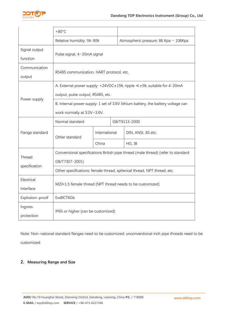
+80°C
Relative humidity: 5%-90% Atmospheric pressure: 86 Kpa ~ 106Kpa
Signal output
function Pulse signal, 4~20mA signal
Communication
output RS485 communication, HART protocol, etc.
Power supply
A. External power supply: +24VDC±15%, ripple ≤±5%, suitable for 4-20mA
output, pulse output, RS485, etc.
B. Internal power supply: 1 set of 3.6V lithium battery, the battery voltage can
work normally at 3.0V~3.6V.
Flange standard
Normal standard GB/T9113-2000
Other standard International DIN, ANSI, JIS etc.
China HG, JB
Thread
specification
Conventional specifications British pipe thread (male thread) (refer to standard
GB/T7307-2001)
Other specifications: female thread, spherical thread, NPT thread, etc.
Electrical
Interface M20*1.5 female thread (NPT thread needs to be customized)
Explosion-proof ExdllCT6Gb
Ingress
protection IP65 or higher (can be customized)
Note: Non-national standard flanges need to be customized; unconventional inch pipe threads need to be
customized.
2. Measuring Range and Size

www.ddtop.com
Dandong TOP Electronics Instrument (Group) Co., Ltd
ADD/ No.10 Huanghai Street, Zhenxing District, Dandong, Liaoning, China P.C. / 118008
E-MAIL / [email protected] SERVICE / +86-415-6227346
Liquid turbine flowmeter measuring range table
Instrument
size (mm )
Normal flow range extended
flow range
Conventional
connection type and
pressure rating
Special pressure
rating (MPa)
Starting
flow
(m3/h)
Maximum
pressure
loss *1
(m3/h) (m3/h) (KPa)
4 0.04~0.25 0.04-0.4 Threaded installation,
6.3 MPa
Clamping
connection<42MPa
0.02 120
6 0.1-0.6 0.06-0.6 Threaded
installation,6.3 MPa 0.05 80
10 0.2~1.2 0.15-1.5 Threaded
installation,6.3 MPa 0.07 50
15 0.6-6 0.5-5 Threaded
installation,6.3 MPa 0.35 35
20 0.8-8 0.45 ~ 9 Threaded
installation,6.3 MPa 0.3 35
25 1-10 0.5 ~ 10 Threaded
installation,6.3MPa 0.4 35
32 1.5-15 0.8-15 Threaded
installation,6.3 MPa 0.6 35
40 2-20 1~20 Threaded
installation,6.3 MPa 0.6 35
50 4~40 2~40 Flange installation,
4.0 MPa
Clamping
connection
<26MPa
1 35
65 7~70 5~70 Flange installation,
1.6MPa 4 25
80 10-100 7-100 Flange installation,
1.6MPa 5 25
100 20 ~ 200 10-200 Flange installation,
1.6 MPa Clamping
connection
<15MPa
8 25
125 25-250 13-250 Flange installation,
1.6 MPa 10 25
150 30-300 15-300 Flange installation,
1.6 MPa 12 25
200 80 ~ 800 40 ~ 800 Flange installation,
1.6 Mpa
Clamping
connection
<11MPa
20 25
Accuracy
level*2 ±0.5% ±1.0% - - - -

www.ddtop.com
Dandong TOP Electronics Instrument (Group) Co., Ltd
ADD/ No.10 Huanghai Street, Zhenxing District, Dandong, Liaoning, China P.C. / 118008
E-MAIL / [email protected] SERVICE / +86-415-6227346
Notes:
1. The maximum pressure loss is the pressure loss when the flowmeter works at the maximum flow point.
The medium is water, and the temperature is normal.
2. Products with an accuracy level of ±0.2% need to be customized, and the flow range is smaller than the
conventional range.
Instrument Classification
1. According to the function of the instrument, the LWGY turbine flowmeter can be divided into 2
categories:
①Turbine flow sensor/transmitter
②Intelligent turbine flowmeter
2. Function description
① N/A Type Turbine Flow Sensor/Transmitter
The N/A turbine flow sensor/transmitter does not have the local display function, and only transmits the
flow signal. The flow signal can be divided into pulse signal or current signal (4-20mA);
The instrument is low in price, high in integration, and small in size. It is especially suitable for the use of
secondary display instrument, PLC, DCS and other computer control systems.
According to different output signals, such products can be divided into pulse output type and 4-20mA
output type
Pulse output type: 12~24VDC power supply, three-wire pulse output, high voltage ≥8V, low voltage
≤0.8V; signal transmission distance ≤1000 meters; pulse=1/2f*1000(ms);
4-20mA output type: 24VDC power supply, two-wire 4-20mA output, signal transmission distance
≤1000 meters.
This kind of turbine flowmeter products are divided into two types: basic type and explosion-proof type
(ExdIICT6 Gb).

www.ddtop.com
Dandong TOP Electronics Instrument (Group) Co., Ltd
ADD/ No.10 Huanghai Street, Zhenxing District, Dandong, Liaoning, China P.C. / 118008
E-MAIL / [email protected] SERVICE / +86-415-6227346
② Intelligent G/E Liquid Turbine Flowmeter
Intelligent liquid turbine flowmeter is a new type of multifunctional and integrated intelligent instrument,
with local indicator, and can also output the flow signal. The series of products using segment code LCD
display, high contrast, low power consumption, two display units can be selected. A variety of electrical signal
output mode can be selected, working conditions equivalent pulse can be set in a variety of output modes,
especially suitable for quantitative control to use. This series of products can not only display the common
volume flow rate unit, but also through the setting of the measured medium density, display the mass flow
rate unit. On the basis of the above functions, in order to meet the different needs, the user can choose to
use the MODBUS protocol based on the RS485 interface communication function.
Power supply DC220V DC24V 3.6V lithium battery
Pulse output Load capacity >1100Ω, High level amplitude >22V, Low level amplitude <0.8V, Pulse
width 1/2fin*1000(ms)
Current output Load capacity 900, two-wire or three-wire 4-20mA, 0-20mA output are optional
Communication
interface
RS485 interface using MODBUS-RTU protocol, HART

www.ddtop.com
Dandong TOP Electronics Instrument (Group) Co., Ltd
ADD/ No.10 Huanghai Street, Zhenxing District, Dandong, Liaoning, China P.C. / 118008
E-MAIL / [email protected] SERVICE / +86-415-6227346
Model Selection Table
Model Contents
LWGY- 口 /口 /口 /口 /口 /口 /口 /口 /口
Instrument
type
N 24V power supply, no local display, pulse output type
A 24V power supply, local display, 4~20 mA output type
G1 Battery power supply, local display, no output
GX External power supply, local display, RS485/current/pulse output
E1 Battery power supply, local display, no output
EX External power supply, local display, RS485/current/pulse output
Connection type
FL Flange connection
LW Thread connection
JZ Clamping connection
Size
4 DN4
6 DN6
10 DN10
15 DN15
20 DN20
52 DN25
32 DN32
40 DN40
50 DN50
65 DN65
80 DN80
100 DN100
125 DN125
150 DN150
200 DN200
Accuracy 05 ±0.5%

www.ddtop.com
Dandong TOP Electronics Instrument (Group) Co., Ltd
ADD/ No.10 Huanghai Street, Zhenxing District, Dandong, Liaoning, China P.C. / 118008
E-MAIL / [email protected] SERVICE / +86-415-6227346
10 ±1.0%
02 ±0.2 (negotiate before, long production cycle)
Measuring range
S Standard range
W Extended range
Z Special range
Body material
S SS304
L SS316(L)
Blade material
S 2Cr13 blade
L Duplex steel blade
Explosion-proof
N No
E ExdIICT6 Gb
Pressure & temperature rating
N Conventional
H(X) High pressure reference table 4-2
Installation Size
1. Threaded Connection Type Size
Threaded Connection Diagram

www.ddtop.com
Dandong TOP Electronics Instrument (Group) Co., Ltd
ADD/ No.10 Huanghai Street, Zhenxing District, Dandong, Liaoning, China P.C. / 118008
E-MAIL / [email protected] SERVICE / +86-415-6227346
Threaded Connection Size Comparison Chart
L* ( mm )
H (mm)
G (male
thread) Pulse
Type
Explosion-proof
pulse type
4-20mA output
type
Intelligent
display
type
4 225 140 145 145 210 G1/2
6 225 140 145 145 210 G1/2
10 345 145 150 145 210 G1/2
15 75 145 150 150 215 G1
20 80 150 155 155 220 G1
25 100 155 160 160 225 G1 1/4
32 140 175 180 180 245 G2
40 140 180 185 180 250 G2
50 150 185 190 190 255 G2 1/2
Note: The above DN4-DN10 flow sensor contains the factory standard straight pipe section size;
DN15-DN50 flow sensor does not contain straight pipe section size.
2. Flange Connection Type Size
Flange Connection Diagram

www.ddtop.com
Dandong TOP Electronics Instrument (Group) Co., Ltd
ADD/ No.10 Huanghai Street, Zhenxing District, Dandong, Liaoning, China P.C. / 118008
E-MAIL / [email protected] SERVICE / +86-415-6227346
Flange Connection Size Comparison Chart
Instrument
size(mm)
L*
(mm)
D
(mm)
K
(mm )
H ( mm)
d
(mm )
n
Standard
Pressure
Rating
Pulse
output
type
Explosion-proof
pulse output
type
4-20mA
output
type
Intelligent
display
type
(number
of
holes)
15 75 95 65 175 180 180 245 14 4
2.5MPa
20 80 105 75 185 190 190 255 14 4
25 100 115 85 200 195 195 260 14 4
32 140 140 100 210 215 215 275 18 4
40 140 150 110 195 220 220 285 18 4
50 150 165 125 230 235 235 295 18 4
65 170 185 145 255 260 260 325 18 8
1.6MPa
80 200 200 160 260 265 265 330 18 8
100 220 220 180 285 285 285 350 18 8
125 250 250 210 310 315 315 380 18 8
150 300 285 240 345 345 345 410 22 8
200 350 340 295 395 400 400 465 22 12
Note: The above DN4-DN10 flow sensor contains the factory standard straight pipe section size;
DN15-DN50 flow sensor does not contain straight pipe section size.
3. Clamping Connection Type Size
Clamping Connection Diagram
www.ddtop.com
Dandong TOP Electronics Instrument (Group) Co., Ltd
ADD/ No.10 Huanghai Street, Zhenxing District, Dandong, Liaoning, China P.C. / 118008
E-MAIL / [email protected] SERVICE / +86-415-6227346
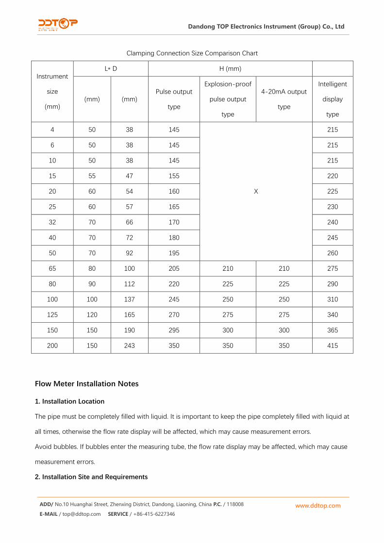
Clamping Connection Size Comparison Chart
Instrument
size
(mm)
L* D H (mm)
(mm) (mm) Pulse output
type
Explosion-proof
pulse output
type
4-20mA output
type
Intelligent
display
type
4 50 38 145
X
215
6 50 38 145 215
10 50 38 145 215
15 55 47 155 220
20 60 54 160 225
25 60 57 165 230
32 70 66 170 240
40 70 72 180 245
50 70 92 195 260
65 80 100 205 210 210 275
80 90 112 220 225 225 290
100 100 137 245 250 250 310
125 120 165 270 275 275 340
150 150 190 295 300 300 365
200 150 243 350 350 350 415
Flow Meter Installation Notes
1. Installation Location
The pipe must be completely filled with liquid. It is important to keep the pipe completely filled with liquid at
all times, otherwise the flow rate display will be affected, which may cause measurement errors.
Avoid bubbles. If bubbles enter the measuring tube, the flow rate display may be affected, which may cause
measurement errors.
2. Installation Site and Requirements
www.ddtop.com
Dandong TOP Electronics Instrument (Group) Co., Ltd
ADD/ No.10 Huanghai Street, Zhenxing District, Dandong, Liaoning, China P.C. / 118008
E-MAIL / [email protected] SERVICE / +86-415-6227346
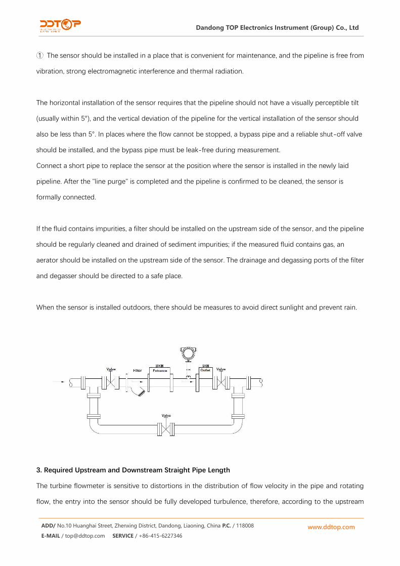
① The sensor should be installed in a place that is convenient for maintenance, and the pipeline is free from
vibration, strong electromagnetic interference and thermal radiation.
The horizontal installation of the sensor requires that the pipeline should not have a visually perceptible tilt
(usually within 5°), and the vertical deviation of the pipeline for the vertical installation of the sensor should
also be less than 5°. In places where the flow cannot be stopped, a bypass pipe and a reliable shut-off valve
should be installed, and the bypass pipe must be leak-free during measurement.
Connect a short pipe to replace the sensor at the position where the sensor is installed in the newly laid
pipeline. After the "line purge" is completed and the pipeline is confirmed to be cleaned, the sensor is
formally connected.
If the fluid contains impurities, a filter should be installed on the upstream side of the sensor, and the pipeline
should be regularly cleaned and drained of sediment impurities; if the measured fluid contains gas, an
aerator should be installed on the upstream side of the sensor. The drainage and degassing ports of the filter
and degasser should be directed to a safe place.
When the sensor is installed outdoors, there should be measures to avoid direct sunlight and prevent rain.
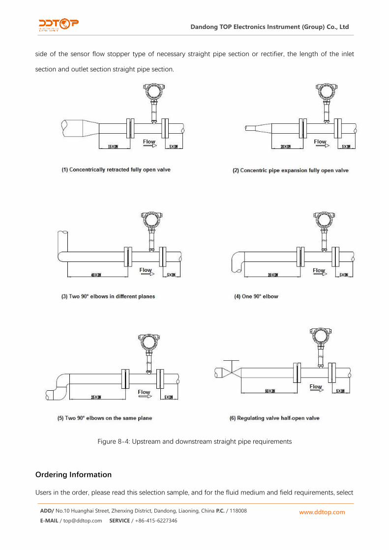
3. Required Upstream and Downstream Straight Pipe Length
The turbine flowmeter is sensitive to distortions in the distribution of flow velocity in the pipe and rotating
flow, the entry into the sensor should be fully developed turbulence, therefore, according to the upstream
www.ddtop.com
Dandong TOP Electronics Instrument (Group) Co., Ltd
ADD/ No.10 Huanghai Street, Zhenxing District, Dandong, Liaoning, China P.C. / 118008
E-MAIL / [email protected] SERVICE / +86-415-6227346
side of the sensor flow stopper type of necessary straight pipe section or rectifier, the length of the inlet
section and outlet section straight pipe section.
Figure 8-4: Upstream and downstream straight pipe requirements
Ordering Information
Users in the order, please read this selection sample, and for the fluid medium and field requirements, select

www.ddtop.com
Dandong TOP Electronics Instrument (Group) Co., Ltd
ADD/ No.10 Huanghai Street, Zhenxing District, Dandong, Liaoning, China P.C. / 118008
E-MAIL / [email protected] SERVICE / +86-415-6227346
a suitable flow meter, and then provide the following information to the manufacturer.
Liquid turbine flow meter models.
The name of the fluid medium and its physical parameters.
Maximum working pressure, maximum working temperature, and minimum working temperature at
which the fluid will operate.
The common flow rate, maximum flow rate, and minimum flow rate of the fluid.