Embed Size (px)
Citation preview

Rafael Flores Luminant PowerSenior Vice President & P 0 Box 1002Chief Nuclear Officer 6322 North FM [email protected] Glen Rose, TX 76043
LuminantT 254.897.5590F 254.897.6652C 817.559.0403
CP-200901560 Ref. # 10 CFR 52Log # TXNB-09064
November 11, 2009
U. S. Nuclear Regulatory CommissionDocument Control DeskWashington, DC 20555ATTN: David B. Matthews, Director
Division of New Reactor Licensing
SUBJECT: COMANCHE PEAK NUCLEAR POWER PLANT, UNITS 3 AND 4DOCKET NUMBERS 52-034 AND 52-035RESPONSES TO REQUESTS FOR ADDITIONAL INFORMATIONNO. 3113, 3315, 3319, 3511, 3674, 3675, 3677, 3705, 3729, 3790, AND 3834
Dear Sir:
Luminant Generation Company LLC (Luminant) herein submits responses to Requests for AdditionalInformation No. 3113, 3315, 3319, 3511, 3674, 3675, 3677, 3705, 3729, 3790, and 3834 for the CombinedLicense Application for Comanche Peak Nuclear Power Plant Units 3 and 4. The affected Final SafetyAnalysis Report pages are included at the end of each attachment.
Should you have any questions regarding these responses, please contact Don Woodlan (254-897-6887,[email protected]) or me.
The commitments made in this letter are specified on page 3.
I state under penalty of perjury that the foregoing is true and correct.
Executed on November 11, 2009.
Sincerely,
Luminant Generation Company LLC
Rafael Flores
-o
U. S. Nuclear Regulatory CommissionCP-200901 560TXNB-0906411/11/2009Page 2 of 3
Attachments 1. Response to Request for Additional Information No. 3113 (CP RAI #90)
2. Response to Request for Additional Information No. 3315 (CP RAI #91)
3. Response to Request for Additional Information No. 3319 (CP RAI #100)
4. Response to Request for Additional Information No. 3511 (CP RAI #99)
5. Response to Request for Additional Information No. 3674 (CP RAI #96)
6. Response to Request for Additional Information No. 3675 (CP RAI #95)
7. Response to Request for Additional Information No. 3677 (CP RAI #94)
8. Response to Request for Additional Information No. 3705 (CP RAI #97)
9. Response to Request for Additional Information No. 3729 (CP RAI #93)
10. Response to Request for Additional Information No. 3790 (CP RAI #98)
11. Response to Request for Additional Information No. 3834 (CP RAI #120)
Electronic Distribution w/all Attachments
[email protected]@[email protected]@[email protected]@[email protected]@[email protected]@[email protected]@[email protected]@[email protected]@[email protected]@[email protected]@[email protected]@[email protected]
Luminant Records Management -Portfolio of .pdf files
[email protected]@[email protected]@mnes-us.comrussell [email protected]@[email protected]@[email protected]@[email protected]@[email protected]@[email protected]@[email protected]@[email protected]@[email protected]@[email protected]@[email protected]@[email protected]@[email protected]
U. S. Nuclear Regulatory CommissionCP-200901560TXNB-090641111/2009Page 3 of 3
Regulatory Commitments in this Letter
This communication contains the following commitments which will be completed or incorporated intothe CPNPP licensing basis as noted. The Commitment Number is used by Luminant for internaltracking.
Number
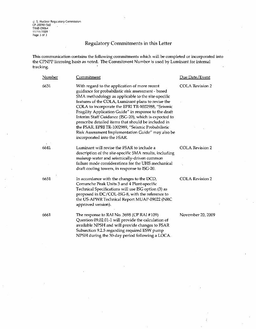
6631
6641
6651
6661
Commitment
With regard to the application of more recentguidance for probabilistic risk assessment - basedSMA methodology as applicable to the site-specificfeatures of the COLA, Luminant plans to revise theCOLA to incorporate the EPRI TR-1002988, "SeismicFragility Application Guide" in response to the draftInterim Staff Guidance (ISG-20), which is expected toprescribe detailed items that should be included inthe FSAR. EPRI TR-1002989, "Seismic ProbabilisticRisk Assessment Implementation Guide" may also beincorporated into the FSAR.
Luminant will revise the FSAR to include adescription of the site-specific SMA results, includingmakeup water and seismically-driven commonfailure mode considerations for the UHS mechanicaldraft cooling towers, in response to ISG-20.
In accordance with the changes to the DCD,Comanche Peak Units 3 and 4 Plant-specificTechnical Specifications will use ISG option (3) asproposed in DC/COL-ISG-8, with the reference tothe US-APWR Technical Report MUAP-09022 (NRCapproved version).
The response to RAI No. 3698 (CP RAI #109)Question 09.02.01-1 will provide the calculation ofavailable NPSH and will provide changes to FSARSubsection 9.2.5 regarding required ESW pumpNPSH during the 30-day period following a LOCA.
Due Date/Event
COLA Revision 2
COLA Revision 2
COLA Revision 2
November 20, 2009
U. S. Nuclear Regulatory CommissionCP-200901 560TXNB-0906411/11/2009
Attachment 1
Response to Request for Additional Information No. 3113 (CP RAI #90)
The following Technical Specification pages are assembled at the end of this attachment:
3.7.9-13.7.9-23.7.9-34.0-1B 3.7.9-1B 3.7.9-2B 3.7.9-3B 3.7.9-4B 3.7.9-5B 3.7.9-6
U. S. Nuclear Regulatory CommissionCP-200901560TXNB-0906411/11/2009Attachment 1Page 1 of 30
RESPONSE TO REQUEST FOR ADDITIONAL INFORMATION
Comanche Peak, Units 3 and 4
Luminant Generation Company LLC
Docket Nos. 52-034 and 52-035
RAI NO.: 3113 (CP RAI #90)
SRP SECTION: 16 - Technical Specifications
QUESTIONS for Technical Specification Branch (CTSB)
DATE OF RAI ISSUE: 9/29/2009
QUESTION NO.: 16-1
NUREG-0800, Standard Review Plan, Chapter 16, "Technical Specifications," establishes criteria thatthe NRC staff intends to use to evaluate whether an applicant meets the NRC's regulations.
TS 3.7.9, Ultimate Heat Sink (UHS).
Provide clarification on the discussion of Surveillance Requirement (SR) 3.7.9.5 in the TS bases B 3.7.9which states, in part, "[T]his SR verifies that each UHS transfer pump starts and operates on an actualor simulated actuation signal." Revise the TS bases B 3.7.9, as appropriate.
Comanche Peak Nuclear Power Plant (CPNPP), Units 3 and 4 combined license application (COLA)FSAR Section 9.2.5.5, states, in part, "[D]uring accident condition, level indications from the operatingbasins~are used to alert the MCR operator to start the UHS transfer pump to transfer water from the idlebasin to the operating basins." This description appears to indicate that operation of an UHS transferpump will be initiated manually by the MCR operator's action, not automatically by an actuation signal.
This clarification is needed to ensure accuracy of supporting information provided in the TS bases.
ANSWER:
Water transfer from one UHS basin to another is conducted by manually operating the UHS transferpumps as described in FSAR Section 9.2.5.5.
Surveillance Requirement 3.7.9.5 is changed to verify start on manual actuation and the discussionunder Surveillance Requirement (SR) 3.7.9.5 in the TS Bases 3.7.9 is revised to indicate that the UHStransfer pumps are manually activated. See also related Question No. 16-7.)
Impact on R-COLA
See attached marked-up TS Draft Revision 1 pages 3.7.9-2 and B 3.7.9-5 at the end of this attachment.

U. S. Nuclear Regulatory CommissionCP-200901560TXNB-0906411711/2009Attachment 1Page 2 of 30
Impact on S-COLA
None.
Impact on DCD
None.

U. S. Nuclear Regulatory CommissionCP-200901560TXNB-0906411/11/2009Attachment IPage 3 of 30
RESPONSE TO REQUEST FOR ADDITIONAL INFORMATION
Comanche Peak, Units 3 and 4
Luminant Generation Company LLC
Docket Nos. 52-034 and 52-035
RAI NO.: 3113 (CP RAI #90)
SRP SECTION: 16- Technical Specifications
QUESTIONS for Technical Specification Branch (CTSB)
DATE OF RAI ISSUE: 9/29/2009
QUESTION NO.: 16-2
NUREG-0800, Standard Review Plan, Chapter 16, "Technical Specifications," establishes criteria thatthe NRC staff intends to use to evaluate whether an applicant meets the NRC's regulations.
TS 3.7.9, Ultimate Heat Sink.
Explain how the Essential Service Water System (ESWS) Pump required net positive suction head(NPSH) is satisfied during the 30 day period following the design basis loss-of-coolant accident (LOCA)without makeup water to the UHS basin. Revise TS 3.7.9 and its associated TS.bases, as appropriate.
SR 3.7.9.1 requires verification of a minimum volume of 2,850,000 gallons in each UHS basin."
The discussion of SR 3.7.9.1 in the TS bases B 3.9.7 states, in part, "[T]his SR verifies that adequatelong term (30 day) cooling can be maintained. The specified level also ensures that sufficient NPSH isavailable to operate the ESWS pumps."
CPNPP FSAR Subsection 9.2.5.3 states, in part, "[T]he total required 30 days cooling water capacity isapproximately 8.54 millions gallons, or approximately 2.85 millions gallons per basin. Each basin .dimension, not including any column or wall sections, is approximately 120 feet x 120 feet with a waterdepth of 29 feet from the minimum maintained water level, the usable water volume available for eachbasin is approximately 3.12 millions gallons." It appears that the ESWS pump NPSH requirement is notconsidered in the specified minimum value of 2.85 millions gallons per basin.
This information is needed to ensure adequacy and completeness of TS 3.7.9 requirements.
ANSWER:
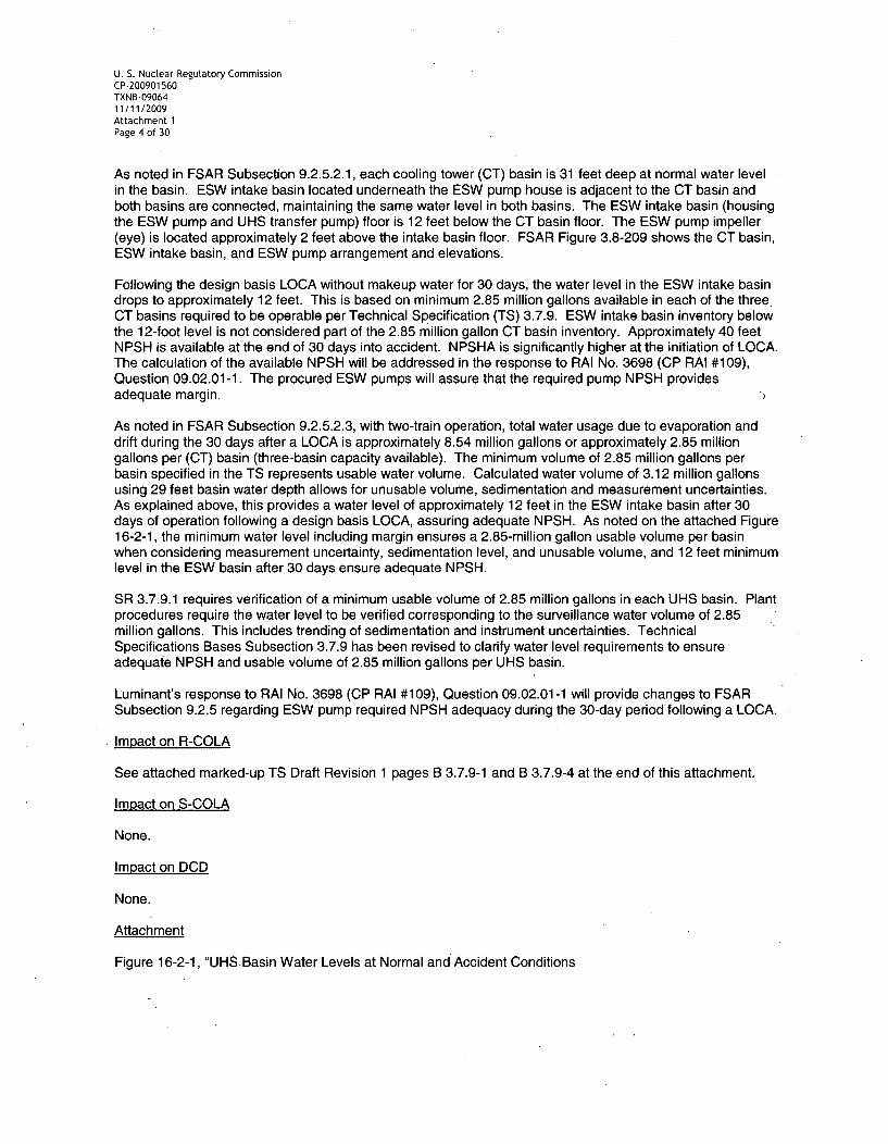
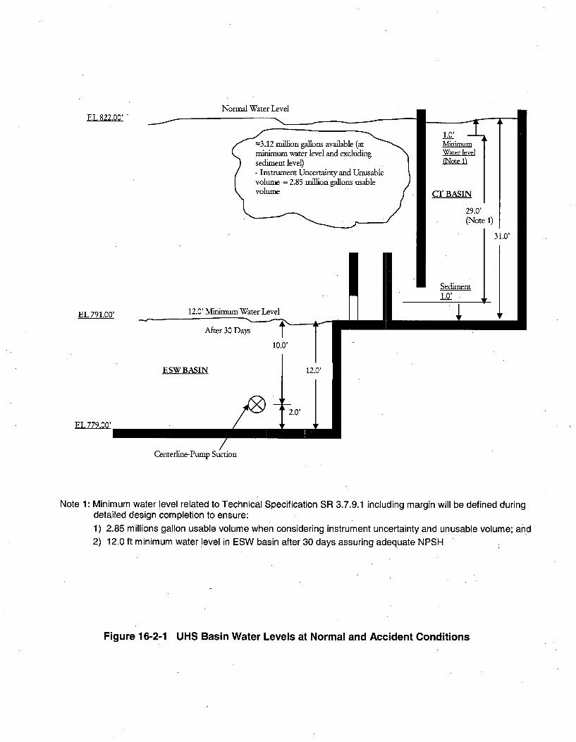
Figure 16-2-1 is attached that depicts basin water levels that are used'for the calculation of available NPSHand the water volume available to support 30 days of operation following a design basis accident withoutmakeup.
U. S. Nuclear Regulatory CommissionCP-200901560TXNB-0906411/11/2009Attachment 1Page 4 of 30
As noted in FSAR Subsection 9.2.5.2.1, each cooling tower (CT) basin is 31 feet deep at normal water levelin the basin. ESW intake basin located underneath the ESW pump house is adjacent to the CT basin andboth basins are connected, maintaining the same water level in both basins. The ESW intake basin (housingthe ESW pump and UHS transfer pump) floor is 12 feet below the CT basin floor. The ESW pump impeller(eye) is located approximately 2 feet above the intake basin floor. FSAR Figure 3.8-209 shows the CT basin,ESW intake basin, and ESW pump arrangement and elevations.
Following the design basis LOCA without makeup water for 30 days, the water level in the ESW intake basindrops to approximately 12 feet. This is based on minimum 2.85 million gallons available in each of the three.CT basins required to be operable per Technical Specification (TS) 3.7.9. ESW intake basin inventory belowthe 12-foot level is not considered part of the 2.85 million gallon CT basin inventory. Approximately 40 feetNPSH is available at the end of 30 days into accident. NPSHA is significantly higher at the initiation of LOCA.The calculation of the available NPSH will be addressed in the response to RAI No. 3698 (CP RAI #109),Question 09.02.01-1. The procured ESW pumps will assure that the required pump NPSH providesadequate margin.
As noted in FSAR Subsection 9.2.5.2.3, with two-train operation, total water usage due to evaporation anddrift during the 30 days after a LOCA is approximately 8.54 million gallons or approximately 2.85 milliongallons per (CT) basin (three-basin capacity available). The minimum volume of 2.85 million gallons perbasin specified in the TS represents usable water volume. Calculated water volume of 3.12 million gallonsusing 29 feet basin water depth allows for unusable volume, sedimentation and measurement uncertainties.As explained above, this provides a water level of approximately 12 feet in the ESW intake basin after 30days of operation following a design basis LOCA, assuring adequate NPSH. As noted on the attached Figure16-2-1, the minimum water level including margin ensures a 2.85-million gallon usable volume per basinwhen considering measurement uncertainty, sedimentation level, and unusable volume, and 12 feet minimumlevel in the ESW basin after 30 days ensure adequate NPSH.
SR 3.7.9.1 requires verification of a minimum usable volume of 2.85 million gallons in each UHS basin. Plantprocedures require the water level to be verified corresponding to the surveillance water volume of 2.85million gallons. This includes trending of sedimentation and instrument uncertainties. TechnicalSpecifications Bases Subsection 3.7.9 has been revised to clarify water level requirements to ensureadequate NPSH and usable volume of 2.85 million gallons per UHS basin.
Luminant's response to RAI No. 3698 (CP RAI #109), Question 09.02.01-1 will provide changes to FSARSubsection 9.2.5 regarding ESW pump required NPSH adequacy during the 30-day period following a LOCA.
Impact on R-COLA
See attached marked-up TS Draft Revision 1 pages B 3.7.9-1 and B 3.7.9-4 at the end of this attachment.
Impact on S-COLA
None.
Impact on DCD
None.
Attachment
Figure 16-2-1, "UHS Basin Water Levels at Normal and Accident Conditions
Normal Water LevelEL 822.00'
,, minimum -water level and excluding) sediment level)/ - Instrument Uncertainty and Unusable
29.0'(Note 1)
EL 791.00' 12.0' Minimum Water Level
After 30 Days
ESW BASIN
Centerline-Pump Suction
Note 1: Minimum water level related to Technical Specification SR 3.7.9.1 including margin will be defined duringdetailed design completion to ensure:
1) 2.85 millions gallon usable volume when considering instrument uncertainty and unusable volume; and2) 12.0 ft minimum water level in ESW basin after 30 days assuring adequate NPSH
Figure 16-2-1 UHS Basin Water Levels at Normal and Accident Conditions
U. S. Nuclear ReguLatory CommissionCP-200901560TXNB-0906411/11/2009Attachment 1Page 6 of 30
RESPONSE TO REQUEST FOR ADDITIONAL INFORMATION
Comanche Peak, Units 3 and 4
Luminant Generation Company LLC
Docket Nos. 52-034 and 52-035
RAI NO.: 3113 (CP RAI #90)
SRP SECTION: 16 - Technical Specifications
QUESTIONS for Technical Specification Branch (CTSB)
DATE OF RAI ISSUE: 9/29/2009
QUESTION NO.: 16-3
NUREG-0800, Standard Review Plan, Chapter 16, "Technical Specifications," establishes criteria that
the NRC staff intends to use to evaluate whether an applicant meets the NRC's regulations.
TS 3.7.9, Ultimate Heat Sink.
Provide justification for the selected completion time (CT) of 7 days for Required Actions C.1 and C.2.1when in Condition C with one or more required UHS transfer pumps inoperable. Revise TS 3.7.9 andits associated TS bases, as appropriate.
Condition C implies all three required UHS transfer pumps may be inoperable indicating a potential lossof the UHS safety.function in a design basis accident event. In accordance with the Westinghousestandard technical specifications (STS), a CT of 1 hour is normally applied in this case.
This information is needed to ensure adequacy of TS 3.7.9 requirements.
ANSWER:
During the worst design basis accident conditions, at least two UHS cooling towers and their associatedfans must be available for heat removal. Assuming that all of the required transfer pumps areinoperable, only two cooling tower basin inventories can be used for cooling. This gives the UHS anapproximate 20-day design heat removal capacity without makeup. The Completion Time of 7 days forrestoring the transfer pumps to operable status is bounded and justified by this 20-day emergencycooling period.
Impact on R-COLA
See attached marked-up TS Draft Revision 1 page B 3.7.9-4 at the end of this attachment.
U. S. Nuclear Regulatory CommissionCP-200901560TXNB-0906411/11/2009Attachment 1Page 7 of 30
Impact on S-COLA
None.
Impact on DCD
None.
U. S. Nuctear Regulatory CommissionCP-200901560TXNB-0906411/11/2009Attachment 1Page 8 of 30
RESPONSE TO REQUEST FOR ADDITIONAL INFORMATION
Comanche Peak, Units 3 and 4
Luminant Generation Company LLC
Docket Nos. 52-034 and 52-035
RAI NO.: 3113 (CP RAI #90)
SRP SECTION: 16 - Technical Specifications
QUESTIONS for Technical Specification Branch (CTSB)
DATE OF RAI ISSUE: 9/29/2009
QUESTION NO.: 16-4
NUREG-0800, Standard Review Plan, Chapter 16, "Technical Specifications," establishes criteria thatthe NRC staff intends to use to evaluate whether an applicant meets the NRC's regulations.
TS 3.7.9, Ultimate Heat Sink.
Provide justification for the selected completion time (CT) of 72 hours for Required Action B.1 when inCondition B with one or more UHS basins with water temperature and/or water level not within limits.Revise TS 3.7.9 and its associated TS bases, as appropriate.
Condition B implies all three required UHS cooling towers may be affected indicating a potential loss ofthe UHS safety function in a design basis accident event. For a similar condition, the WestinghouseSTS suggests using an alternate indication to ensure that loss of the UHS safety function will not occur(e.g. verification that the average temperature for the previous 24 hours is within limits) with a CT of 1hour which is normally applied to an unanalyzed plant condition.
This information is needed to ensure adequacy of TS 3.7.9 requirements.
ANSWER:
Action B is being divided into two separate Actions B and C to address basin temperature and waterlevel, respectively. Required Action B.1 and its corresponding Completion Time have been changed tothe verification of the average temperature for the previous 24 hours and once per hour, respectively.The new Condition C and its corresponding Completion Time are added to allow an independentverification of the water level - a crucial parameter in maintaining the UHS safety function. The 72-hourCompletion Time for the new Required Action C.1 is consistent with that of A.1. See also relatedQuestion 16-8. The water level dropping below normal during a 72-hour period does not cause asignificant loss in the UHS cooling capacity because there would be ample cooling basin inventory forheat removal during the worst accident conditions. The UHS has approximately 20 days to remove thedesign heat load with two cooling tower basins and 30 days with three cooling tower basins available.

U. S. Nuclear Regulatory CommissionCP-200901560TXNB-0906411/11/2009Attachment 1Page 9 of 30
In addition, the explanation of Condition B and new Condition C has been changed from "One or more
UHS basins with ... " to "One or more required UHS basins with ... " to precisely explain the condition.
The Bases for the Actions of these two separate Conditions have been revised accordingly.
Impact on R-COLA
See attached marked-up TS Draft Revision 1 pages 3.7.9-1, 3.7.9-2, B 3.7.9-3, and B 3.7.9-4 at the endof this attachment.
Impact on S-COLA
None.
Impact on DCD
None.

U. S. Nuclear Regulatory CommissionCP-200901560TXNB-0906411/11/2009Attachment 1Page 10 of 30
RESPONSE TO REQUEST FOR ADDITIONAL INFORMATION
Comanche Peak, Units 3 and 4
Luminant Generation Company LLC
Docket Nos. 52-034 and 52-035
RAI NO.: 3113 (CP RAI #90)
SRP SECTION: 16 - Technical Specifications
QUESTIONS for Technical Specification Branch (CTSB)
DATE OF RAI ISSUE: 9/29/2009
QUESTION NO.: 16-5
NUREG-0800, Standard Review Plan, Chapter 16, "Technical Specifications," establishes criteria that
the NRC staff intends to use to evaluate whether an applicant meets the NRC's regulations.
TS 3.7.9, Ultimate Heat Sink.
Provide justification for not including testing of various newly added UHS motor operated valves (MOVs)and control valves to verify their operability in TS 3.7.9. Revise TS 3.7.9 and its associated TS bases,as appropriate.
CPNPP FSAR Table 9.2.5-202 shows the site-specific UHS equipments which include cooling towerfans, transfer pumps, pump discharge MOVs, transfer line basin inlet MOVs and basin blowdowncontrol valves. Cooling tower fan operability is verified in SRs 3.7.9.3 and 3.7.9.4. Transfer pumpoperability is verified in SR 3.7.9.5. No SR was provided for the valves.
This is needed to ensure adequacy and completeness of TS 3.7.9 requirements.
ANSWER:
All UHS valves related to safety, including the newly added UHS MOVs and control valves, are tested toverify their operability in TS 3.7.9. The TS bases are revised accordingly.
Impact on R-COLA
See attached marked-up TS Draft Revision 1 pages 3.7.9-3 and B 3.7.9-6 at the end of this attachment.
Impact on S-COLA
None.

U. S. Nuclear Regulatory CommissionCP-200901560TXNB-0906411/11/2009Attachment 1Page 11 of 30
Impact on DCD
None.
U. S. Nuclear Regulatory CommissionCP-200901560TXNB-0906411/11/2009Attachment IPage 12 of 30
RESPONSE TO REQUEST FOR ADDITIONAL INFORMATION
Comanche Peak, Units 3 and 4
Luminant Generation Company LLC
Docket Nos. 52-034 and 52-035
RAI NO.: 3113 (CP RAI #90)
SRP SECTION: 16 - Technical Specifications
QUESTIONS for Technical Specification Branch (CTSB)
DATE OF RAI ISSUE: 9/29/2009
QUESTION NO.: 16-6
NUREG-0800, Standard Review Plan, Chapter 16, "Technical Specifications," establishes criteria thatthe NRC staff intends to use to evaluate whether an applicant meets the NRC's regulations.
TS 3.7.9, Ultimate HeatSink.
Provide clarification on SR 3.7.9.4 which states "[V]erify each cooling tower fan starts automatically onan actual or simulated actuation signal."
CPNPP FSAR Subsection 9.2.5,. Ultimate Heat Sink, does not provide a clear description of how UHScooling tower fan operation can be initiated in a design basis accident event.
This clarification is needed to ensure accuracy and completeness of TS 3.7.9 requirements and relevantinformation in the FSAR.
ANSWER:
The cooling tower fans have protection and safety monitoring system (PSMS) control functions toensure uninterrupted operation of the UHS. The operation of the fans during abnormal and accidentconditions is triggered by the emergency core cooling system (ECCS) actuation, LOOP sequence andremote manual actuation signals.
A similar explanation is added to FSAR Subsection 9.2.5.2.2, "System Operation."
Impact on R-COLA
See attached marked-up FSAR Draft Revision 1 page 9.2-9.

U. S. Nuclear Regulatory CommissionCP-200901560TXNB-0906411/11/2009Attachment 1Page 13 of 30
Impact on S-COLA
None.
Impact on DCD
None.
Comanche Peak Nuclear Power Plant, Units 3 & 4COL Application
Part 2, FSAR
water level annunciation in the main control room (MCR) indicates a malfunctionof the makeup control valve or the blowdown control valve.
Adequate NPSH is maintained under all operating modes, includingloss-of-coolant accident (LOCA) and LOOP, with one train out of service formaintenance, when the source of makeup water is assumed lost for a period ofthirty days after the accident. During such conditions, the combined inventory ofthree basins provides a thirty-day cooling water supply assuming the worstcombination of meteorological conditions and accident heat loads.
The UHS transfer pumps and the ESWPs located in each basin are powered bythe different Class 1 E buses, e.g., for basin A, the ESWP is powered from bus A,and the UHS transfer pump is powered from bus C or D, depending on manualbreaker alignment.
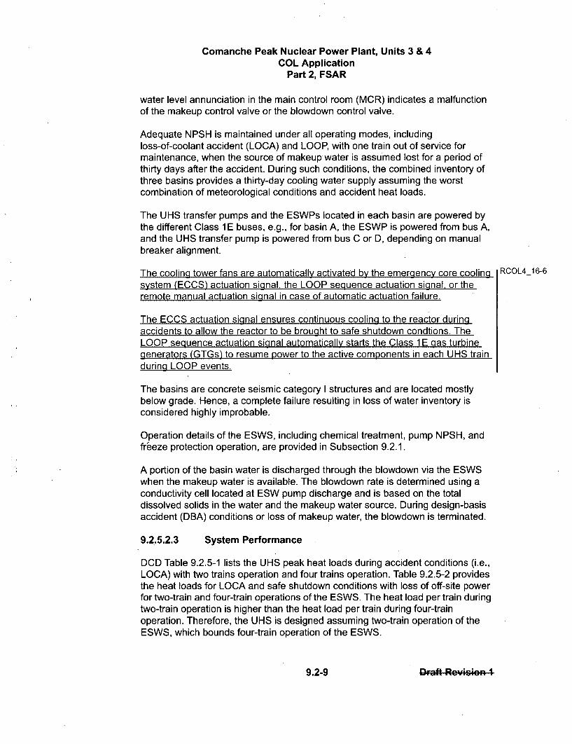
The cooling tower fans are automatically activated by the emergency core cooling RCOL4_16-6system (ECCS) actuation signal, the LOOP sequence actuation signal, or theremote manual actuation signal in case of automatic actuation failure.
The ECCS actuation signal ensures continuous cooling to the reactor duringaccidents to allow the reactor to be brought to safe shutdown condtions. TheLOOP sequence actuation signal automatically starts the Class 1 E gas turbinegenerators (GTGs) to resume power to the active components in each UHS trainduring LOOP events.
The basins are concrete seismic category I structures and are located mostlybelow grade. Hence, a complete failure resulting in loss of water inventory isconsidered highly improbable.
Operation details of the ESWS, including chemical treatment, pump NPSH, andfreeze protection operation, are provided in Subsection 9.2.1.
A portion of the basin water is discharged through the blowdown via the ESWSwhen the makeup water is available. The blowdown rate is determined using aconductivity cell located at ESW pump discharge and is based on the totaldissolved solids in the water and the makeup water source. During design-basisaccident (DBA) conditions or loss of makeup water, the blowdown is terminated.
9.2.5.2.3 System Performance
DCD Table 9.2.5-1 lists the UHS peak heat loads during accident conditions (i.e.,LOCA) with two trains operation and four trains operation. Table 9.2.5-2 providesthe heat loads for LOCA and safe shutdown conditions with loss of off-site powerfor two-train and four-train operations of the ESWS. The heat load per train duringtwo-train operation is higher than the heat load per train during four-trainoperation. Therefore, the UHS is designed assuming two-train operation of theESWS, which bounds four-train operation of the ESWS.
9.2-9 92Daft RoycIo. I
U. S. Nuclear Regulatory CommissionCP-200901560TXNB-0906411/11/2009Attachment 1Page 15 of 30
RESPONSE TO REQUEST FOR ADDITIONAL INFORMATION
Comanche Peak, Units 3 and 4
Luminant Generation Company LLC
Docket Nos. 52-034 and 52-035
RAI NO.: 3113 (CP RAI #90)
SRP SECTION: 16 - Technical Specifications
QUESTIONS for Technical Specification Branch (CTSB)
DATE OF RAI ISSUE: 9/29/2009
QUESTION NO.: 16-7
TS 3.7.9, Ultimate Heat Sink.
EDITORIAL
(1) Page B 3.7.9-5, SURVEILLANCE REQUIREMENTS, SR 3.7.9.5, last sentence: The phrase "inserviceinspections" should be "inservice testing."
(2) Page B 3.7.9-5, REFERENCES, first reference: "FSAR Chapter 9" should be "FSAR Subsection 9.2.5."
ANSWER:
The Surveillance Frequency requirement has been changed to follow the Surveillance FrequencyControl Program instead of the Inservice Testing Program, thus, the editorial correction in item 1 is notneeded.
The editorial correction in item 2 has been reflected in the FSAR subsection concerned.
Impact on R-COLA
See attached marked-up TS Draft Revision 1 pages 3.7.9-2, B 3.7.9-5, and B 3.7.9-6 at the end of thisattachment.
Impact on S-COLA
None.
Impact on DCD
None.
U. S. Nuclear Regulatory CommissionCP-200901560TXNB-0906411/11/2009Attachment IPage 16 of 30
RESPONSE TO REQUEST FOR ADDITIONAL INFORMATION
Comanche Peak, Units 3 and 4
Luminant Generation Company LLC
Docket Nos. 52-034 and 52-035
RAI NO.: 3113 (CP RAI #90)
SRP SECTION: 16 - Technical Specifications
QUESTIONS for Technical Specification Branch (CTSB)
DATE OF RAI ISSUE: 9/29/2009
QUESTION NO.: 16-8
NUREG-0800, Standard Review Plan, Chapter 16, "Technical Specifications," establishes criteria thatthe NRC staff intends to use to evaluate whether an applicant meets the NRC's regulations.
TS 3.7.9, Ultimate Heat Sink.
Provide justification for the selected completion time (CT) of 7 days for Required Action A.1 when inCondition A with one required cooling tower inoperable. Revise TS 3.7.9 and its associated TS bases,as appropriate.
Each independent cooling tower operation is in direct support of the respective ESWS train operation.The 7-day CT for Required Action A.1 in TS 3.7.9 is not consistent with the 72-hour CT for RequiredAction A.1 in TS 3.7.8 when in Condition A with one required ESWS train inoperable.
This information is needed to ensure consistency of requirements in related TS 3.7.8 and TS 3.7.9.
ANSWER:
Condition A of TS 3.7.9 is equivalent to Condition A of TS 3.7.8, which has a Completion Time of 72hours, and has been changed accordingly.
Impact on R-COLA
See attached marked-up TS Draft Revision 1 pages 3.7.9-1, B 3.7.9-2, and B 3.7.9-3 at the end of thisattachment.
Impact on S-COLA
None.

U. S. Nuclear ReguLatory CommissionCP-200901560TXNB-090641111/2009Attachment 1Page 17 of 30
Impact on DCD
None.
U. S. Nuclear Regulatory CommissionCP-200901560TXNB-0906411/11/2009Attachment 1Page 18 of 30
RESPONSE TO REQUEST FOR ADDITIONAL INFORMATION
Comanche Peak, Units 3 and 4
Luminant Generation Company LLC
Docket Nos. 52-034 and 52-035
RAI NO.: 3113 (CP RAI #90)
SRP SECTION: 16 - Technical Specifications
QUESTIONS for Technical Specification Branch (CTSB)
DATE OF RAI ISSUE: 9/29/2009
QUESTION NO.: 16-9/1
TS 4.1, Site Location.
Verify that the description of site location in TS 4.1 reflects relevant information provided in FSARsubsection 2.1.1.1. Revise TS 4.1, as appropriate.
The description for CPNPP site location provided in TS 4.1 is not consistent with details provided inFSAR subsection 2.1.1.1.
This is needed to ensure accuracy of information provided in TS 4.1.
ANSWER:
The description of the site location in TS 4.1 has been revised.
Impact on R-COLA
See attached marked-up TS Draft Revision 1 page 4.0-1 at the end of this attachment.
Impact on S-COLA
None.
Impact on DCD
None.

U. S. Nuclear Regulatory CommissionCP-200901560TXNB-0906411/11/2009Attachment 1Page 19 of 30
RESPONSE TO REQUEST FOR ADDITIONAL INFORMATION
Comanche Peak, Units 3 and 4
Luminant Generation Company LLC
Docket Nos. 52-034 and 52-035
RAI NO.: 3113 (CP RAI #90)
SRP SECTION: 16 - Technical Specifications
QUESTIONS for Technical Specification Branch (CTSB)
DATE OF RAI ISSUE: 9/29/2009
QUESTION NO.: 16-10
NUREG-0800, Standard Review Plan, Chapter 16, "Technical Specifications," establishes criteria thatthe NRC staff intends to use to evaluate whether an applicant meets the NRC's regulations.
TS 5.5.19, Surveillance Frequency Control Program (SFCP).
Provide the list of Frequencies of those Surveillance Requirements for which the Frequency iscontrolled by the program.
The plant-specific technical specifications (PTS) are stand alone entity with the issuance of a COL.This list of Frequencies is needed by the COL holder to fully develop and implement the SFCP prior tothe plant initial fuel loading. Further, Frequencies for SRs specified in TS 3.7.9 for the plant UltimateHeat Sink were not provided as part of the MHI APWR generic technical specifications (GTS) scope.
This information is needed to ensure completeness of TS 5.5.19 requirements.
ANSWER:
The surveillance frequencies of plant facilities for Comanche Peak Units 3 and 4 are to be controlled bythe Surveillance Frequency Control Program (SFCP) using the Risk-Informed Method. The SFCP willbe developed prior to initial fuel loading as part of implementing the Technical Specifications (TS) andspecifically implementing the SFCP. The list of frequencies for those Surveillance Requirements, forwhich the Frequency is controlled by the program, will be developed and contained in the SFCP.
The Surveillance Requirements have already been identified in COLA Part 4 'Technical Specifications"while the deterministic values of the frequencies for the US-APWR SSCs can be found in Chapter 16'Technical Specifications" of US-APWR DCD. The Ultimate Heat Sink is a site-specific system and isnot included in the US-APWR generic technical specifications. The Surveillance Requirements,

U. S. Nuclear Regulatory CommissionCP-200901560TXNB-0906411/111/2009Attachment 1Page 20 of 30
including the deterministic values of the surveillance frequencies for TS 3.7.9, Ultimate Heat Sink, areprovided below.
Deterministic Values of Surveillance Frequencies for Ultimate Heat Sink
SURVEILLANCE FREQUENCY
SR 3.7.9.1 Verify each required UHS basin water level is ? 2,850,000 24 hoursgallons.
SR 3.7.9.2 Verify water temperature of UHS is < 950f. 24 hours
SR 3.7.9.3 Operate each cooling tower fan for > 15 minutes. 31 days
SR 3.7.9.4 Verify each cooling tower fan starts automatically on an actual 24 monthsor simulated actuation signal.
SR 3.7.9.5 Verify UHS transfer pump starts on manual actuation. 24 months
SR 3.7.9.6 Verify each UHS manual, power operated, and automatic 31 daysvalve in the flow path servicing safety related equipment, that is notlocked, sealed, or otherwise secured in position, is in the correct position.
SR 3.7.9.7 Verify each UHS automatic valve and each control valve in the 24monthsflow path that is not locked, sealed, or otherwise secured in position,actuates to the correct position on an actual or simulated actuation signal.
Impact on R-COLA
None.
Impact on S-COLA
None.
Impact on DCD
None.
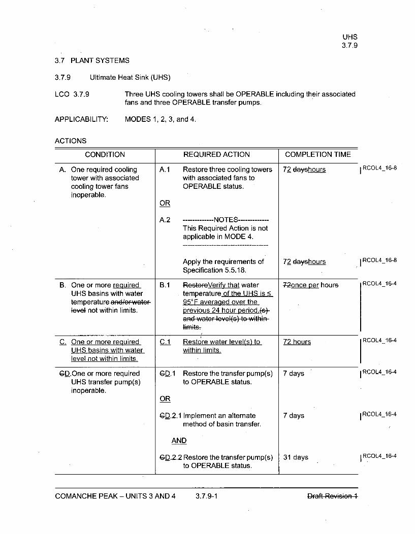
UHS3.7.9
3.7 PLANT SYSTEMS
3.7.9 Ultimate Heat Sink (UHS)
LCO 3.7.9
APPLICABILITY:
Three UHS cooling towers shall be OPERABLE including their associatedfans and three OPERABLE transfer pumps.
MODES 1, 2, 3, and 4.
ACTIONS
CONDITION REQUIRED ACTION COMPLETION TIME
A. One required cooling A.1 Restore three cooling towers 72 dayshours I RCOL4_16-8
tower with associated with associated fans tocooling tower fans OPERABLE status.inoperable.
OR
A.2 --------- NOTES------This Required Action is notapplicable in MODE 4.
Apply the requirements of 72 dayshours RCOL4-16-8
Specification 5.5.18.
B. One or more required B.1 ReVteFe~erify that water -72once per hours RCOL4_16-4
UHS basins with water temperature of the UHS is <temperature and/Fwa•teF 95°F averaged over the4e'el not within limits, previous 24 hour period.%-
and water lcvcl(s) to within
C. One or more required C.1 Restore water level(s) to 72 hours RCOL4_16-4
UHS basins with water within limits.level not within limits.
GD.One or more required GD.1 Restore the transfer pump(s) 7 days I RCOL4_16-4
UHS transfer pump(s) to OPERABLE status.inoperable.
OR
GD.2.1 Implement an alternate 7 days 1RCOL4-16-4
method of basin transfer.
AND
GD.2.2 Restore the transfer pump(s) 31 days I RCOL4-16-4
to OPERABLE status.
COMANCHE PEAK - UNITS 3 AND 4 3.7.9-1 DFaft Reymsm
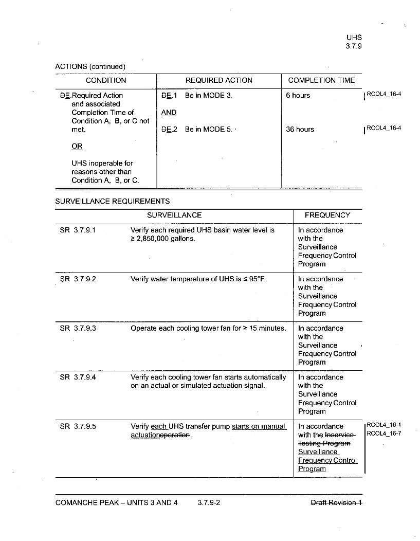
UHS3.7.9
ACTIONS (continued)
CONDITION REQUIRED ACTION COMPLETION TIME
DE.Required Action DE.1 Be in MODE 3. 6 hours I RCOL4_16-4
and associatedCompletion Time of ANDCondition A, B, or C notmet. lQE.2 Be in MODE 5. 36 hours I RCOL4_16-4
OR
UHS inoperable forreasons other thanCondition A, B, or C.
SURVEILLANCE REQUIREMENTS
SURVEILLANCE FREQUENCY
SR 3.7.9.1 Verify each required UHS basin water level is In accordance> 2,850,000 gallons. with the
SurveillanceFrequency ControlProgram
SR 3.7.9,2 Verify water temperature of UHS is < 950F. In accordancewith theSurveillanceFrequency ControlProgram
SR 3.7.9.3 Operate each cooling tower fan for > 15 minutes. In accordancewith theSurveillanceFrequency ControlProgram
SR 3.7.9.4 Verify each cooling tower fan starts automatically In accordanceon an actual or simulated actuation signal. with the
SurveillanceFrequency ControlProgram
SR 3.7.9.5 Verify each UHS transfer pump starts on manual In accordance RCOL4_16-1
actuationeperAthAR. with the 4nc;r'-!oP RCOL4_16-7
TetigPFGefRfafSurveillanceFrequency ControlProgram
COMANCHE PEAK - UNITS 3 AND 4 3.7.9-2 DFaft Revisi
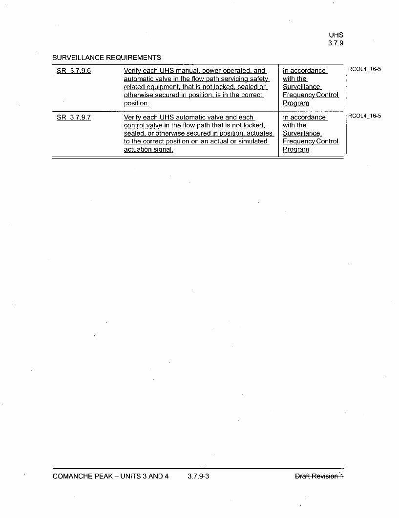
UHS3.7.9
SURVEILLANCE REQUIREMENTS
SR 3.7.9.6 Verify each UHS manual, power-operated, and In accordanceautomatic valve in the flow path servicing safety with therelated equipment, that is not locked, sealed or Surveillanceotherwise secured in position, is in the correct Frequency Controlposition. Program
SR 3.7.9.7 Verify each UHS automatic valve and each In accordancecontrol valve in the flow path that is not locked, with thesealed, or otherwise secured in position, actuates Surveillanceto the correct position on an actual or simulated Frequency Controlactuation signal. Proaram
RCOL4_16-5
RCOL4_16-5
COMANCHE PEAK - UNITS 3 AND 4 3.7.9-3 nmft R visieq.A. 1.
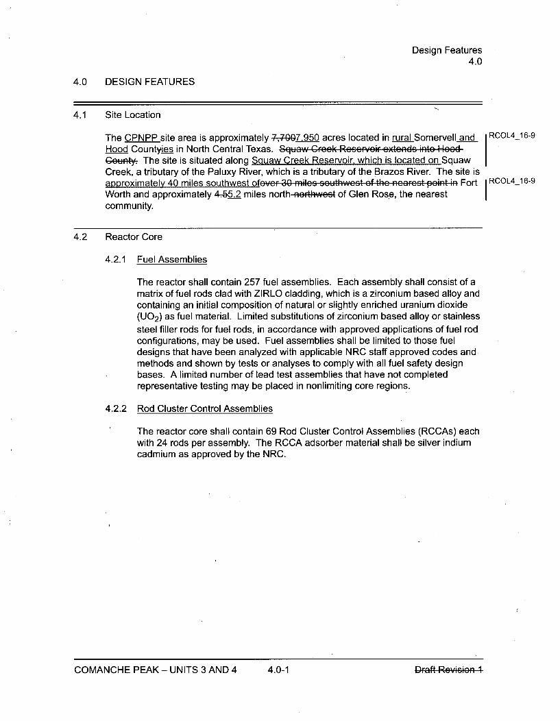
Design Features4.0
4.0 DESIGN FEATURES
4.1 Site Location
The CPNPP site area is approximately 7-0.50 acres located in rural Somervell andHood Countyies in North Central Texas. Squaw Crcck Rcsc,-cir cxtcnds into HocdGeuty. The site is situated along Squaw Creek Reservoir, which is located on SquawCreek, a tributary of the Paluxy River, which is a tributary of the Brazos River. The site isapproximately 40 miles southwest ofovcr 30 mules s,. thwczt of the ncaFrct p.int in FortWorth and approximately 4-.5.2 miles north nerthwest of Glen Rose, the nearestcommunity.
4.2 Reactor Core
4.2.1 Fuel Assemblies
The reactor shall contain 257 fuel assemblies. Each assembly shall consist of amatrix of fuel rods clad with ZIRLO cladding, which is a zirconium based alloy andcontaining an initial composition of natural or slightly enriched uranium dioxide(U0 2 ) as fuel material. Limited substitutions of zirconium based alloy or stainlesssteel filler rods for fuel rods, in accordance with approved applications of fuel rodconfigurations, may be used. Fuel assemblies shall be limited to those fueldesigns that have been analyzed with applicable NRC staff approved codes and.methods and shown by tests or analyses to comply with all fuel safety designbases. A limited number of lead test assemblies that have not completedrepresentative testing may be placed in nonlimiting core regions.
4.2.2 Rod Cluster Control Assemblies
RCOL4_16-9
RCOL4_ 6-9
The reactor core shall contain 69 Rod Cluster Control Assemblies (RCCAs) eachwith 24 rods per assembly. The RCCA adsorber material shall be silver indiumcadmium as approved by the NRC.
COMANCHE PEAK - UNITS 3 AND 4 4.0-1

UHSB 3.7.9
B 3.7 PLANT SYSTEMS
B 3.7.9 Ultimate Heat Sink (UHS)
BASES
BACKGROUND The UHS provides a heat sink for processing and operating heat fromsafety related components during a transient or accident, as well as duringnormal operation. This is done by utilizing the Essential Service WaterSystem (ESWS) and the Component Cooling Water (CCW) System.
The UHS consists of four 50 percent capacity mechanical draft coolingtowers, one for each ESWS train. Each cooling tower consists of two cellswith one fan per cell. The combined inventory of three of the four UHSbasins provides a 30-day storage capacity as discussed in FSAR Chapter 9(Ref. 1). Each unit is provided with its own independent UHS with no crossconnection between the two units. The two principal functions of the UHSare the dissipation of residual heat after reactor shutdown, and dissipationof residual heat after an accident.
The basic performance requirements are that an adequate inventory ofcooling water be available for 30 days without makeup, and that the designbasis temperatures of safety related equipment not be exceeded. EachUHS basin provides 33-1/3 percent of the combined inventory for the30-day storage capacity to satisfy the short-term recommendation ofRegulatory Guide 1.27 (Ref. 2). There is one safety-related UHS transferpump per UHS basin which is used to transfer water between the UHSbasins.
The stored water level provides adequate net positive suction head (NPSH)to the ESW pump during a 30-day period of operation following the designbasis LOCA without makeup.
Additional information on the design and operation of the system, alongwith a list of components served, can be found in Reference 1.
RCOL4_16-2
COMANCHE PEAK - UNITS 3 AND 4 B 3.7.9-1 Draft Rcvklon ICOMANCHE PEAK - UNITS 3 AND 4 B 3.7.9-1 Dlaft Rey•sme"vl
UHSB 3.7.9
BASES
APPLICABLESAFETYANALYSES
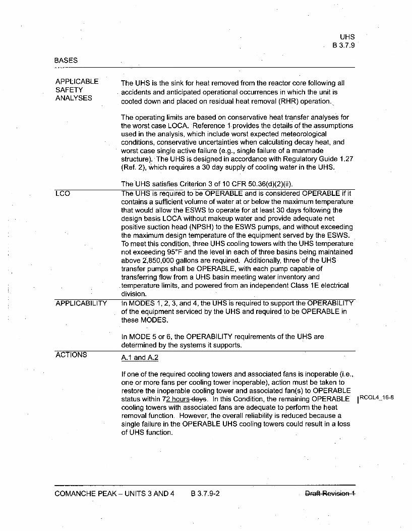
The UHS is the sink for heat removed from the reactor core following allaccidents and anticipated operational occurrences in which the unit iscooled down and placed on residual heat removal (RHR) operation.
The operating limits are based on conservative heat transfer analyses forthe worst case LOCA. Reference 1 provides the details of the assumptionsused in the analysis, which include worst expected meteorologicalconditions, conservative uncertainties when calculating decay heat, andworst case single active failure (e.g., single failure of a manmadestructure). The UHS is designed in accordance with Regulatory Guide 1.27(Ref. 2), which requires a 30 day supply of cooling water in the UHS.
The UHS satisfies Criterion 3 of 10 CFR 50.36(d)(2)(ii).
LCO The UHS is required to be OPERABLE and is considered OPERABLE if itcontains a sufficient volume of water at or below the maximum temperaturethat would allow the ESWS to operate for at least 30 days following thedesign basis LOCA without makeup water and provide adequate netpositive suction head (NPSH) to the ESWS pumps, and without exceedingthe maximum design temperature of the equipment served by the ESWS.To meet this condition, three UHS cooling towers with the UHS temperaturenot exceeding 950F and the level in each of three basins being maintainedabove 2,850,000 gallons are required. Additionally, three of the UHStransfer pumps shall be OPERABLE, with each pump capable oftransferring flow from a UHS basin meeting water inventory and
• temperature limits, and powered from an independent Class 1 E electricaldivision.
APPLICABILITY In MODES 1, 2, 3, and 4, the UHS is required to support the OPERABILITYof the equipment serviced by the UHS and required to be OPERABLE inthese MODES.
In MODE 5 or 6, the OPERABILITY requirements of the UHS aredetermined by the systems it supports.
ACTIONS A.1 and A.2
If one of the required cooling towers and associated fans is inoperable (i.e.,one or more fans per cooling tower inoperable), action must be taken torestore the inoperable cooling tower and associated fan(s) to OPERABLEstatus within 72 hours-days. In this Condition, the remaining OPERABLE IRCOL4916-8cooling towers with associated fans are adequate to perform the heatremoval function. However, the overall reliability is reduced because asingle failure in the OPERABLE UHS cooling towers could result in a lossof UHS function.
COMANCHE PEAK - UNITS 3 AND 4 B 3.7.9-2 Dr.F-.I. Re.-,,as*, "

UHSB 3.7.9
BASES
ACTIONS (continued)
Required Action A.2 allows the option to apply the requirements ofSpecification 5.5.18 to determine a Risk Informed Completion Time (RICT).This Required Action is not applicable in MODE 4. The 72-hour-dayCompletion Time is based on the capability of the OPERABLE coolingtowers to provide the UHS cooling capability and the low probability of anaccident occurring during the 72 hours-days that one required cooling towerand associated fans are inoperable.
B..1
With water temperature of the UHS > 95°F, the design basis assumptionassociated with initial UHS temperature is bounded provided thetemperature of the UHS averaged over the previous 24-hour period is <950F. With the water temperature of the UHS > 95WF. long-term coolingcapability of the ECCS loads may be affected. Therefore, to ensurelong-term cooling capability is provided to the ECCS loads when watertemperature of the UHS is > 950 F, Required Action B.1 is provided tomonitor the water temperature of the UHS more frequently and verify thetemperature is < 95 0F when averaged over the previous 24 hour period.The once per hour Completion Time takes into consideration UHStemperature variations and the increased monitoring frequency needed toensure design basis assumptions and equipment limitations are notexceeded in this condition. If the water temperature of the UHS exceeds95°F when averaged over the previous 24 hour period, Condition E mustbe entered immediately.
8C. 1
If one or more required UHS basins have a watcr tcmperaturc and/or waterlevel not within the limits, action must be taken to restore the watertempef,.e.....d level to within limits within 72 hours.
The 72 hour Completion Time is reasonable based on the low probability ofan accident occurring during the 72 hours, the considerable coolingcapacity still available in the basin(s), and the time required to reasonablycomplete the Required Action. Furthermore, there would be no significantloss in the UHS cooling capacity when the water level drops below thenormal level during a 72-hour period because of sufficient cooling towerbasin inventory. The UHS has a combined design heat removal capacity ofapproximately 20 days from two operable cooling tower basins and 30 daysfrom three operable cooling tower basins.
I RCOL4_16-8
I RCOL4_16-8
RCOL4_16-4
I RCOL4-16-4
RCOL4_16-4
GD.1, GD.2.1, and GD.2.2
If one or more required UHS transfer pump(s) are inoperable, action must
COMANCHE PEAK - UNITS 3 AND 4 B 3.7.9-3 Draft Rcvizion 1COMANCHE PEAK - UNITS 3 AND 4 B 3.7.9-3 DFaft Rey*s4

UHSB 3.7.9
BASES
ACTIONS (continued)be taken to restore the pump(s) to OPERABLE status or implement analternate method of transferring the affected basin within 7 days. If analternate method is utilized, action still must be taken to restore the transferpump(s) to OPERABLE status within 31 days.
The Completion Times are reasonable based on the low probability of anaccident occurring during the time allowed to restore the pump(s) orimplement an alternate method, the availability of alternate methods, andthe amount of time available to transfer the water from one basin to theother under the worst case accident assumptions. Furthermore, theinoperability of all required transfer pumps leaves only two cooling towerbasins with a combined design heat removal capacity of approximately 20days. This cooling period bounds and justifies the 7-day completion time torestore the transfer pumps to operable status.
RCOL4_16-3
9E.1 and .E.2 RCOL4 16-4
If the Required Actions and Completion Times of Condition A, B, or C arenot met, or the UHS is inoperable for reasons other than Condition A, B, orC, the unit must be placed in a MODE in which the LCO does not apply. Toachieve this status, the unit must be placed in at least MODE 3 within6 hours and in MODE 5 within 36 hours.
The allowed Completion Times are reasonable, based on operatingexperience, to reach the required unit conditions from full power conditionsin an orderly manner and without challenging unit systems.
SURVEILLANCEREQUIREMENTS
SR 3.7.9.1
This SR verifies that adequate long term (30 day) cooling can bemaintained. The specified level also ensures that sufficient NPSH isavailable to operate the ESWS pumps. The Surveillance Frequency isbased on operating experience, equipment reliability, and plant risk and iscontrolled under the Surveillance Frequency Control Program. This SRverifies that each required UHS basin water level is > 2,850,000gallons. Plant procedures provide the corresponding water level to beverified to assure a usable volume of 2,850,00 gallons, accounting forunusable volume and measurement uncertainty.
SR 3.7.9.2
This SR verifies that the ESWS is available to cool the CCW System andessential chiller unit to at least its maximum design temperature with themaximum accident or normal design heat loads for 30 days following a
RCOL4_16-2
/
COMANCHE PEAK - UNITS 3 AND 4 B 3.7.9-4 Draft Rcvkion 1COMANCHE PEAK - UNITS 3 AND 4 B 3.7.9-4 DFaft Reyffisffi

UHSB 3.7.9
BASES
SURVEILLANCE REQUIREMENTS (continued)
Design Basis Accident. The Surveillance Frequency is based on operatingexperience, equipment reliability, and plant risk and is controlled under theSurveillance Frequency Control Program. This SR verifies that the watertemperature of the UHS is < 950F.
SR 3.7.9.3
Operating each cooling tower fan for >15 minutes ensures that all fans areOPERABLE and that all associated controls are functioning properly. Italso ensures that fan or motor failure, or excessive vibration, can bedetected for corrective action. The Surveillance Frequency is based onoperating experience, equipment reliability, and plant risk and is controlledunder the Surveillance Frequency Control Program.
SR 3.7.9.4
This SR verifies that each UHS fan starts and operates on an actual orsimulated actuation signal. The Surveillance Frequency is based onoperating experience, equipment reliability, and plant risk and is controlledunder the Surveillance Frequency Control Program.
SR 3.7.9.5
This SR verifies that each UHS transfer pump starts and operates on--aea-actual Or simulatcda manual actuation signal. Verification of the UHStransfer pump operation includes testing to verify the pump's developedhead at the flow test point is greater than or equal to the requireddeveloped head. Testing also includes verification of required valvepositions.
The Frogueney of this SR is n accorFdanco with the Inccrwiee TestingProgramR of the ASME Gedc. The ASME Godc provides the activiticc andFrcqucncicc ncccccar; to satisfy' the rcquircmcnts. Such inscrviccW nspcctiens confiFrm cmponcnt OPERABILIT*, trond pecfGFmancc, andd•tett incipicnt fai.-... by indicating abnOFrmal pcf, rmancc. TheSurveillance Frequency is based on operating experience, equipmentreliability, and plant risk and is controlled under the Surveillance FrequencyControl Program.
I RCO L4 _16-1
RCOL4_16-7
COMANCHE PEAK - UNITS 3 AND 4 B 3.7.9-5 Draft Rovicion 1COMANCHE PEAK - UNITS 3 AND 4 B 3.7.9-5 n.-roD ,i-it
UHSB 3.7.9
BASES
ACTIONS (continued)SR 3.7.9.6 RCOL4_16-5
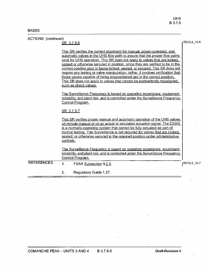
This SR verifies the correct alignment for manual, power-operated, andautomatic valves in the UHS flow path to assure that the proper flow pathsexist for UHS operation. This SR does not apply to valves that are locked,sealed or otherwise secured in position, since they are verified to be in thecorrect position prior to being locked, sealed, or secured. This SR does notrequire any testing or valve manipulation: rather. it involves verification thatthose valves capable of being mispositioned are in the correct position.This SR does not apply to valves that cannot be inadvertently misaligned,such as check valves.
The Surveillance Frequency is based on operating experience, equipmentreliability, and plant risk, and is controlled under the Surveillance FrequencyControl Program.
SR 3.7.9.7
This SR verifies'proper manual and automatic operation of the UHS valveson remote manual or on an actual or simulated actuation signal. The ESWSis a normally-operating system that cannot be fully actuated as part ofnormal testing. This Surveillance is not required for valves that are locked,sealed, or otherwise secured in the required position under administrativecontrols.
The Surveillance Frequency is based on operating experience, equipmentreliability, and plant risk, and is controlled under the Surveillance FrequencyControl Program.
REFERENCES 1. FSAR Subsection 9.2.5.
2. Regulatory Guide 1.27.
I RCOL4_16-7
COMANCHE PEAK - UNITS 3 AND 4 B 3.7.9-6

U. S. Nuclear Regulatory CommissionCP-200901560TXNB-0906411/11/2009
Attachment 2
Response to Request for Additional Information No. 3315 (CP RAI #91)
The following pages are assembled at the end of this attachment:
FSAR1.8-641.8-651.8-66
Tech Spec12356
14151.1-23.1.9-33.3.1-133.3.1-143.3.1-153.3.1-163.3.1-173.3.1-183.3.1-193.3.1-20
3.3.1-213.3.2-123.3.2-133.3.2-143.3.2-153.3.2-163.3.2-173.3.2-183.3.2-193.3.2-203.3.2-21
3.3.2-223.3.5-23.3.6-43.3.6-55.5-205.5-215.5-22B 3.3.1-2B 3.3.1-5B 3.3.1-6B 3.3.1-7B 3.3.1-8
B 3.3.1-41B 3.3.1-49B 3.3.2-2B 3.3.2-3B 3.3.2-4B 3.3.2-5B 3.3.2-6B 3.3.2-34B 3.3.2-54B 3.3.2-56B 3.3.2-57B 3.3.5-1
B 3.3.5-5B 3.3.5-6B 3.3.6-3B 3.3.6-5B 3.3.6-6B.3.3.6-10
U. S. Nuclear Regulatory CommissionCP-200901560TXNB-0906411/11/2009Attachment 2Page 1 of 83
RESPONSE TO REQUEST FOR ADDITIONAL INFORMATION
Comanche Peak, Units 3 and 4
Luminant Generation Company LLC
Docket Nos. 52-034 and 52-035
RAI NO.: 3315 (CP RAI #91)
SRP SECTION: 16 - Technical Specifications
QUESTIONS for Technical Specification Branch (CTSB)
,DATE OF RAI ISSUE: 9/29/2009
QUESTION NO.: 16-11
LCO 3.3, Instrumentation
Revise the Instrumentation Bases references to 10 CFR 50.36(d)(2)(ii) in the Comanche Peak Units 3and 4 Bases.
10 CFR 50.36, 'Technical Specifications," has been amended by changing the designation of paragraph(d) to paragraph (c), in order to resolve administrative issues. Correct the 10 CFR 50.36 reference inthe following Limiting Condition for Operation (LCO) Bases Sections of the Comanche Peak Units 3 and4 Instrumentation Bases.
" B 3.3.1, Reactor Trip System (RTS) Instrumentation, page B 3.3.1-28
* B 3.3.2, Engineered Safety Feature Actuation System (ESFAS) Instrumentation, page B 3.3.2-38
* B 3.3.4, Remote Shutdown Console (RSC), page B 3.3.4-1
* B 3.3.5, Loss of Power (LOP) Class 1 E GTG Start Instrumentation, page B 3.3.5-2
* B 3.3.6, Diverse Actuation System (DAS) Instrumentation, page B 3.3.6-5
The revisions are needed to ensure the accuracy and completeness of the Comanche Peak, Units 3and 4 Bases.
ANSWER:
These changes have been incorporated in COLA Part 4 Technical Specifications Update TrackingReport Revision 0 (TXNB-09043 dated September 16, 2009) (ML092660191) and are attached for thereviewer's convenience.
U. S. Nuclear Regulatory CommissionCP-200901 560TXNB-0906411/11/2009Attachment 2Page 2 of 83
Impact on R-COLA
None.
Impact on S-COLA
None
Impact on DCD
None.
Attachment
COLA Part 4 Technical Specifications Update Tracking Report Revision 0, pages B 3.3.1-28,B 3.3.2-40, B 3.3.4-1, B 3.3.5-2, and B 3.3.6-5.

U. S. Nuclear Regulatory CommissionCP-200901560TXNB-0906411/11/2009Attachment 2Page 3 of 83
COLA Part 4 UTR Rev. 0 page B 3.3.1-28

U. S. Nuclear Regulatory CommissionCP-200901560TXNB-0906411/11/2009Attachment 2Page 4 of 83
COLA Part 4 UTR Rev. 0 page B 3.3.1-40

U. S. Nuclear Regulatory CommissionCP-200901560TXNB-0906411/11/2009Attachment 2Page 5 of 83
COLA Part 4 UTR Rev. 0 page B 3.3.4-1

U. S. Nuclear Regulatory CommissionCP-200901560TXNB-0906411/11/2009Attachment 2Page 6 of 83
COLA Part 4 UTR Rev. 0 page B 3.3.5-2

U. S. Nuclear Regulatory CommissionCP-200901560TXNB-0906411/11/2009Attachment 2Page 7 of 83
COLA Part 4 UTR Rev. 0 page B 3.3.6-5

U. S. Nuclear Regulatory CommissionCP-200901560TXNB-0906411/11/2009Attachment 2Page 8 of 83
RESPONSE TO REQUEST FOR ADDITIONAL INFORMATION
Comanche Peak, Units 3 and 4
Luminant Generation Company LLC
Docket Nos. 52-034 and 52-035
RAI NO.: 3315 (CP RAI #91)
SRP SECTION: 16- Technical Specifications
QUESTIONS for Technical Specification Branch (CTSB)
DATE OF RAI ISSUE: 9/29/2009
QUESTION NO.: 16-12
LCO 3.3.1, RTS Instrumentation
Revise the Comanche Peak Units 3 and 4 PTS to correct editorial and reference errors identified inTable 3.3.1-1.
The Comanche Peak Units 3 and 4 PTS, Table 3.3.1-1, pages 3.3.1-18, 3.3.1-21, and 3.3.1-22 containthe following editorial and reference errors:
* Table 3.3.1-1, Functions 15.c and 15.d, page 3,3.1-18, need spaces between the Trip Setpointvalues of 10% and Units of rated thermal power (RTP).
* Table 3.3.1-1, Note 1: Overtemperature AT, page 3.3.1-21, incorrectly specifies T and T'instead of Tavg and Tavgo, respectively, in the term descriptions.
* Table 3.3.1-1, Note 2: Overpower AT, page 3.3.1-22, incorrectly specifies T and T" instead ofTavg and Tavgo, respectively, for the K9 term.
The revisions are needed to ensure the accuracy and consistency of the Comanche Peak, Units 3 and4 PTS.
ANSWER:
For the first bullet, these values and the abbreviation RTP are deleted to be consistent with the changesbased on Question No. 16-16. The editorial and reference errors in the second and third bullets havebeen corrected in the attached mark-up.
Impact on R-COLA
See attached marked-up Part 4 Technical Specifications Draft Revision 1 pages 3.3.1-20 and 3.3.1-21at the end of this attachment.

U. S. Nuclear Regulatory CommissionCP-200901560TXNB-0906411/11/2009Attachment 2Page 9 of 83
Impact on S-COLA
None.
Impact on DCD
None.
U. S. Nuclear Regulatory CommissionCP-200901560TXNB-0906411/11/2009Attachment 2Page 10 of 83
RESPONSE TO REQUEST FOR ADDITIONAL INFORMATION
Comanche Peak, Units 3 and 4
Luminant Generation Company LLC
Docket Nos. 52-034 and 52-035
RAI NO.: 3315 (CP RAI #91)
SRP SECTION: 16 - Technical Specifications
QUESTIONS for Technical Specification Branch (CTSB)
DATE OF RAI ISSUE: 9/29/2009
QUESTION NO.: 16-13
LCO 3.3.2, ESFAS Instrumentation
Provide the additional information and any changes necessary to explain and correct a potentialdiscrepancy regarding the omission of US APWR Bases information from the SURVEILLANCEREQUIREMENTS (SR) Section of the Comanche Peak Units 3 and 4 Bases.
The Comanche Peak Units 3 and 4 Bases, SURVEILLANCE REQUIREMENTS, SR 3.3.2.4 (page B3.3.2-53), omits the third sentence of the corresponding paragraph in the US APWR Bases,SURVEILLANCE REQUIREMENTS, which states that "[t]he Actuation Outputs are solid state devices."SR 3.3.2.4 is the performance of a Trip Actuating Device Operational Test (TADOT) for the ActuationOutputs of all Engineered Safety Feature Actuation System (ESFAS) functions. It is unclear why thisstatement, which appears to be relevant, would be excluded from the Bases of SR 3.3.2.4, yet retainedin the Bases discussions of both SR 3.3.5.5 (TADOT for the Actuation Outputs to start the Class 1 EGTGs) and SR 3.3.6.5 (TADOT for the Actuation Outputs of all Diverse Actuation System functions).Determine if the referenced statement should be included in the Bases for SR 3.3.2.4 and make anynecessary corrections.
The additional information is needed to ensure the accuracy and completeness of the Comanche PeakUnits 3 and 4 Bases.
ANSWER:
The statement 'The Actuation Outputs are solid state devices" is necessary in the description of SR3.3.2.4 and has been revised accordingly.
Impact on R-COLA
See attached marked-up Part 4 Technical Specifications Draft Revision 1 page B 3.3.2-56 at the end ofthis attachment.

U. S. Nuclear Regulatory CommissionCP-200901560TXNB-0906411/11/2009Attachment 2Page 11 of 83
Impact on S-COLA
None
Impact on DCD
None
U. S. Nuclear ReguLatory CommissionCP-200901560TXNB-0906411/11/2009Attachment 2Page 12 of 83
RESPONSE TO REQUEST FOR ADDITIONAL INFORMATION
Comanche Peak, Units 3 and 4
Luminant Generation Company LLC
Docket Nos. 52-034 and 52-035
RAI NO.: 3315 (CP RAI #91)
SRP SECTION: 16 - Technical Specifications
QUESTIONS for Technical Specification Branch (CTSB)
DATE OF RAI ISSUE: 9/29/2009
QUESTION NO.: 16-14
LCO 3.3.2, ESFAS Instrumentation
Revise the Comanche Peak Units 3 and 4 Bases to correct editorial errors identified in Bases Section B3.3.2, ESFAS Instrumentation.
The Comanche Peak Units 3 and 4 Bases, ESFAS Instrumentation (B 3.3.2), pages B 3.3.2-5 and B3.3.2-7 contain the following editorial errors:
* The Comanche Peak Units 3 and 4 Bases, BACKGROUND, page B 3.3.2-5 (secondparagraph), misspells the word "self-tested" in the first sentence.
* The Comanche Peak Units 3 and 4 Bases, APPLICABILITY SAFETY ANALYSES, LCO andAPPLICABILITY, page B 3.3.2-7 (sixth bullet), misspells the word "Pump" in the second line.
The revisions are needed to ensure the accuracy and consistency of the Comanche Peak Units 3 and 4Bases.
ANSWER:
The description on page B 3.3.2-5 has been revised to incorporate the comment in the first bullet. Thechange requested in the second bullet was incorporated in COLA Part 4 Technical SpecificationsUpdate Tracking Report Revision 0 (TXNB-09043 dated September 16, 2009) (ML092660191) pageB 3.3.2-7 and is attached for the reviewer's convenience.
Impact on R-COLA
See attached marked-up Part 4 Technical Specifications Draft Revision 1,. page B 3.3.2-5 at the end ofthis attachment.
Impact on S-COLA
None
U. S. Nuclear Regulatory CommissionCP-200901560TXNB-0906411/11/2009Attachment 2Page 13 of 83
Impact on DOD
None.
Attachment
COLA Part 4 Technical Specifications Update Tracking Report Revision 0, page B 3.3.2-7.

U. S. Nuclear Regulatory CommissionCP-200901560TXNB-0906411/11/2009Attachment 2Page 14 of 83
COLA Part 4 Technical Specifications Update Tracking Report Revision 0, page B 3.3.2-7.

U. S. Nuclear Regulatory CommissionCP-200901560TXNB-0906411/11/2009Attachment 2Page 15 of 83
RESPONSE TO REQUEST FOR-ADDITIONAL INFORMATION
Comanche Peak, Units 3 and 4
Luminant Generation Company LLC
Docket Nos. 52-034 and 52-035
RAI NO.: 3315 (CP RAI #91)
SRP SECTION: 16 - Technical Specifications
QUESTIONS for Technical Specification Branch (CTSB)
DATE OF RAI ISSUE: 9/29/2009
QUESTION NO.: 16-15
NUREG-0800, Standard Review Plan, Chapter 16, "Technical Specifications," establishes criteria thatthe NRC staff intends to use to evaluate whether an applicant meets the NRC's regulations.
LCO 3.3.5, LOP Class 1 E [gas turbine generator] GTG Start Instrumentation
Provide a technical justification for the Time Delay values specified in Table 3.3.2-1 and SurveillanceRequirement (SR) 3.3.5.3 of the Comanche Peak Units 3 and 4 PTS.
The Comanche Peak Units 3 and 4 PTS, Table 3.3.2-1, Function 6.e (LOOP Signal), specifies a 2-second time delay for the Emergency Feedwater Actuation - Loss of Offsite Power Function. Inaddition, the Comanche Peak, Units 3 and 4 TS, SR 3.3.5.3, page 3.3.5-2, specifies 2-second and 10-second time delays for loss of voltage and degraded voltage conditions, respectively. The selection ofthese time delays, which differ from the bracketed values specified in the US APWR Generic TS, isspecifically addressed in Section A of Part 4 (Technical Specifications) of the Comanche Peak, Units 3and 4 COL Application. The justification provided in both cases states "[e]stablishes consistency withCPNPP Units 1 and 2 Technical Requirements Manual." It is unclear how the selection of time delayvalues for a new design which incorporates the use of Gas Turbine Generators, can be adequatelyjustified on the basis of establishing consistency with the Technical Requirements Manual for the twooperating CPNPP Units. Provide a technical justification that addresses the basis for the time delayvalues specified.
The technical justification is needed to ensure the accuracy and completeness of the Comanche PeakUnits 3 and 4 PTS.
ANSWER:
The bracketed time delay values for Emergency Feedwater Actuation in Table 3.3.2-1 and loss ofvoltage and degraded voltage in SR 3.3.5.3 of the US-APWR DCD Chapter 16 are site-specific values.Loss of voltage protection is also used as Emergency Feed Water Actuation. The time delay of the lossof voltage protection and degraded voltage protection were determined based on the following:

U. S. Nuclear Regulatory CommissionCP-200901560TXNB-0906411/11/2009Attachment 2Page 16 of 83
Loss of voltage protection
The purpose of this protection is to protect voltage sensitive loads, such as motors, whenever the busvoltage drops below the acceptable value. For equipment protection, only a short time is allowed togive the grid a chance to recover. Since the transmission system for Units 3 and 4 is provided by thesame Transmission Service Provider and associated with the same power pool as Units 1 and 2, thesetting of Units 1 and 2 was duplicated.
The two-second delay is desirable since the normal supply is from a transmission line that hasautomatic re-closing. The preferred outcome for a trip-out of the normal supply line is for the line to re-close and the plant to be back on its normal supply. The two-second delay allows time for the normalsupply line to trip from both ends, "dead line" re-close from one end and synchro-check from the otherto return the line to service. This way transient faults, such as lightning, will not result in unnecessarytransfers.
Degraded voltaqe protection
The purpose of this protection is to assure that the plant equipment is not impacted by voltagedegradation in the local grid (no faults present). Therefore, a longer time is allowed to give the grid achance to recover. Since all Comanche Peak Units are equipped with similar plant equipment, thesetting of Units 1 and 2 was duplicated.
The degraded voltage could be caused by an electrical fault that is slow to clear, but once cleared thevoltage will return to normal. The degraded voltage could also be caused by a large motor havingtrouble starting. Ten seconds should be long enough to allow the motor to start or trip. Once the motorstarts or trips, the voltage will recover. Times shorter than ten seconds could result in unnecessarytransfers.
As stated above, time delay for loss of voltage and degraded voltage protection were determinedindependent of gas turbine generator considerations. Based on the above, the CPNPP Units 1 and 2time delays were determined to be appropriate for CPNPP Units 3 and 4 in COLA.
COLA Part 4 Section A has been revised to clarify these justifications.
Impact on R-COLA
See attached marked-up Part 4 Technical Specifications Draft Revision 1 page 6 at the end of thisattachment.
Impact on S-COLA
None.
Impact on DCD
None.
U. S. Nuclear Regulatory CommissionCP-200901560TXNB-0906411/11/2009Attachment 2Page 17 of 83
RESPONSE TO REQUEST FOR ADDITIONAL INFORMATION
Comanche Peak, Units 3 and 4
Luminant Generation Company LLC
Docket Nos. 52-034 and 52-035
RAI NO.: 3315 (CP RAI #91)
SRP SECTION: 16 - Technical Specifications
QUESTIONS for Technical Specification Branch (CTSB)
DATE OF RAI ISSUE: 9/29/2009
QUESTION NO.: 16-16
LCO 3.3, Instrumentation
Provide the additional information and make the necessary changes to propose Plant-SpecificTechnical Specifications (PTS) that are complete and contain sufficient information to support issuanceof a combined license (COL).
On December 9, 2008, the NRC issued Final Interim Staff Guidance Document DC/COL-ISG-8,"Necessary Content of Plant-Specific Technical Specifications When a Combined License Is Issued."The interim staff guidance (ISG) clarifies NRC position on what constitutes an acceptable set of Plant-Specific Technical Specifications required for a COL applicant to demonstrate compliance with Sections182a and 185b of the Atomic Energy Act and 10 CFR Part 52.
The ISG specifically states that "[t]o comply with the Act and the regulations applicable to PTS issuedwith a COL referencing a standard DC rule, present and future COL applicants shall propose PTScontaining all site-specific information that is necessary to ensure plant operation within its design basis.The COL applicant shall confirm all preliminary information and provide all missing information that isdenoted in the generic technical specifications by bracketed values, reviewer's notes, or any otherplaceholder. The PTS issued with the COL will be complete and will contain no COL action (orinformation) items for the COL holder to resolve (i.e., completing the PTS). The COL will contain nolicense condition on completing the PTS."
The ISG also states:
"Present and future COL applicants shall resolve all generic technicalspecification COL action (or information) items before COL issuance. The COLapplicant may propose to resolve each such item using one of the following threeoptions, listed in order of preference:
(1) Provide a plant-specific value.
(2) Provide a value that bounds the plant-specific value, but which the plant maybe safely operated (i.e., a usable bounding value).
U. S. Nuclear Regulatory CommissionCP-200901560TXNB-0906411/11/2009Attachment 2Page 18 of 83
(3) Establish a PTS Section 5.5 or 5.6 administrative controls program or report.
Such an administrative controls technical specification as described in option (3)shall require (a) use of an NRC-reviewed and -approved methodology fordetermining the plant-specific value, (b) establishment of an associateddocument, outside the PTS, in which the relocated plant-specific value shall berecorded and maintained, and (c) any other information or restrictions the NRCstaff deems necessary and appropriate to satisfy 10 CFR 50.36. For example,some COL applicants have proposed an administrative controls technicalspecification for a setpoint control program to satisfy 10 CFR 50.26(c)(1)(ii)(A) inlieu of specifying explicit values for the limiting safety system settings in the PTS.
Options (2) and (3) should allow an applicant to provide the necessaryinformation without relying on information that is impractical to obtain before thetime of COL issuance (i.e., information such as design detail, equipmentselection, as-built system configuration, and system test results)."
The following COL Holder Items were identified in the Comanche Peak Units 3 and 4 PTS, Section 3.3,and Bases, Section B.3.3, Instrumentation:
* In PTS Table 3.3.1-1, the brackets were removed and the following NOTE added: "[i]n all case,the values specified for Allowable Values and Setpoints will be confirmed following completionof the plant specific setpoint study. These values will be calculated in accordance with thesetpoint methodology after selection of plant specific instrumentations."
* In PTS Table 3.3.1-1, Note 1: Overtemperature AT, page 3.3.1-20, brackets were retained forthe % RTP (DNB Protection) and % RTP (Core Exit Boiling Limit) Allowable Value limits.
* In PTS Table 3.3.1-1, Note 2: Overpower AT, page 3.3.1-22, brackets were retained for the %RTP Allowable Value limit.
* Bases B 3.3.1, APPLICABLE SAFETY ANALYSES, LCO, and APPLICABILITY, page B 3.3.1-8(third paragraph), incorporates the following additional text: "[i]n Table 3.3.1-1, the valuesspecified for Allowable Values and Setpoints will be confirmed following completion of the plantspecific setpoint study. These values will be calculated in accordance with the setpointmethodology after selection of plant specific instrumentations."
* In PTS Table 3.3.2-1, the brackets were removed and the following NOTE added: "[iun all case,the values specified for Allowable Values and Setpoints will be confirmed following completionof the plant specific setpoint study. These values will be calculated in accordance with thesetpoint methodology after selection of plant specific instrumentations."
* Bases B 3.3.2, APPLICABLE SAFETY ANALYSES, LCO, and APPLICABILITY, page B 3.3.2-6(second paragraph), incorporates the following additional text: "[i]n Table 3.3.2-1, the valuesspecified for Allowable Values and Setpoints will be confirmed following completion of the plantspecific setpoint study. These values will be calculated in accordance with the setpointmethodology after selection of plant specific instrumentations."
* In Surveillance Requirement (SR) 3.3.5.3, the brackets were removed and the following NOTEadded: "[i]n all case, the values specified for Setpoints will be confirmed following completion ofthe plant specific setpoint study. These values will be calculated in accordance with thesetpoint methodology after selection of plant specific instrumentations."

U1. S. Nuclear Regulatory CommissionCP-200901560TXNB-0906411/11/2009Attachment 2Page 19 of 83
0 Bases B 3.3.5, SURVEILLANCE REQUIREMENTS, page B 3.3.5-6 (second paragraph),incorporates the following additional text: "[i]n SR 3.3.5.3, the values specified for Setpoints willbe confirmed following completion of the plant specific setpoint study. These values will becalculated in accordance with the setpoint methodology after selection of plant specificinstrumentations."
In PTS Table 3.3.6-1, the brackets were removed and the following NOTE added: "[i]n all case,the values specified for Allowable Values and Setpoints will be confirmed following completionof the plant specific setpoint study. These values will be calculated in accordance with thesetpoint methodology after selection of plant specific instrumentations."
Bases B 3.3.6, APPLICABLE SAFETY ANALYSES, LCO, and APPLICABILITY, page B 3.3.6-6(second paragraph), incorporates the following additional text: "[i]n Table 3.3.6-1, the valuesspecified for Allowable Values and Setpoints will be confirmed following completion of the plantspecific setpoint study. These values will be calculated in accordance with the setpointmethodology after selection of plant specific instrumentations."
Resolve the COL Holder Items in accordance with the referenced interim staff guidance. ProposePlant-Specific Technical Specifications for Instrumentation that are complete and contain no COL action(or information) items. For an applicant selecting Option (3) of DC/COL-ISG-8, the NRC staff requeststhe applicant model the Setpoint Control Program (SCP) Specification based on the SCP Specificationdeveloped in the ESBWR DC review, with suitable terminology changes to conform to the ComanchePeak, Units 3 and 4 setpoint methodology. In addition, each CHANNEL CALIBRATION SR shall state:"Perform CHANNEL CALIBRATION on each required channel consistent with Specification 5.5.XX,"Setpoint Control Program (SCP)." It is the NRC staff's position that conformance to the model will benecessary to conclude that the Setpoint Control Program satisfies 10 CFR 50.36(c)(1)(ii)(A).
ANSWER:
The following approach will be implemented to incorporate DC/COL-ISG-8.
(1) MHI plans to submit Technical Report MUAP-09022 "US-APWR Instrument Setpoint Methodology"currently scheduled for November 2009 in accordance with the response of Topical Report MUAP-07004* RAI (UAP-HF-09261). This report defines the calculation methodology for each setpoint and
allowable value.
* MUAP-07004, MHI Topical Report, "Safety I&C System Description and Design Process"
(2) Bracketed setpoints and allowable values including related COL Holder items [i.e., 16.13.3.1 (1),16.1_3.3.2(1), 16.1-3.3.5(1), and 16.1-3.3.6(1)] have been removed from the DCD GTS (GeneralTechnical Specifications).
(3) In accordance with the changes to the DCD, Comanche Peak Units 3 and 4 PTS (Plant-specificTechnical Specifications) will use ISG option (3) as proposed in DC/COL-ISG-8, with the reference tothe US-APWR Technical Report MUAP-09022 (NRC approved version).
The Setpoint Control Program is added in COLA Part 4 Section 5.5 "Programs and Controls," and allsetpoints and allowable values in Specifications are removed.
The US-APWR Technical Report MUAP-09022 has not yet been approved by the NRC. Therefore, anew COL item is added so that the COL applicant updates the reference information of the US-APWRTechnical Report MUAP-09022 in the PTS after NRC approval.
U. S. Nuclear Regulatory CommissionCP-200901560TXNB-0906411/11/2009Attachment 2Page 20 of 83
Descriptions of setpoints and allowable values in COLA Part 4, specified in the question, have beenrevised as follows;
* In PTS Table 3.3.1-1, the brackets were removed and the following NOTE added: "[i]n all case,the values specified for Allowable Values and Setpoints will be confirmed following completionof the plant specific setpoint study. These values will be calculated in accordance with thesetpoint methodology after selection of plant specific instrumentations."
In COLA Marked-up, pages 3.3.1-13 to 3.3.1-18All specific setpoints and allowable values including NTOE have been deleted from PTS Table3.3.-i.
* In PTS Table 3.3.1-1, Note 1: Overtemperature AT, page 3.3.1-20, brackets were retained forthe % RTP (DNB Protection) and % RTP (Core Exit Boiling Limit) Allowable Value limits.
In COLA Marked-up, page 3.3.1-19Description of specific allowable values for Overtemperature AT has been deleted from PTSTable 3.3.1-1, Note 1.
* In PTS Table 3.3.1-1, Note 2: Overpower AT, page 3.3.1-22, brackets were retained for the %RTP Allowable Value limit.
In COLA Marked-up, page 3.3.1-21Description of specific allowable value for Overpower AT has been deleted from PTS Table3.3.1-1, Note 2.
* Bases B 3.3.1, APPLICABLE SAFETY ANALYSES, LCO, and APPLICABILITY, page B 3.3.1-8(third paragraph), incorporates the following additional text: "[i]n Table 3.3.1-1, the valuesspecified for Allowable Values and Setpoints will be confirmed following completion of the plantspecific setpoint study. These values will be calculated in accordance with the setpointmethodology after selection of plant specific instrumentations."
In COLA Marked-up, page B 3.3.1-8This paragraph has been deleted from PTS Section 3.3.1 Bases.
* In PTS Table 3.3.2-1, the brackets were removed and the following NOTE added: "[i]n all case,the values- specified for Allowable Values and Setpoints will be confirmed following completionof the plant specific setpoint study. These values will be calculated in accordance with thesetpoint methodology after selection of plant specific instrumentations."
In COLA Marked-up, pages 3.3.2-12 to 3.3.2-22All specific setpoints and allowable values including NTOE have been deleted from PTS Table3.3.2-1.
* Bases B 3.3.2, APPLICABLE SAFETY ANALYSES, LCO, and APPLICABILITY, page B 3.3.2-6(second paragraph), incorporates the following additional text: "[i]n Table 3.3.2-1, the valuesspecified for Allowable Values and Setpoints will be confirmed following completion of the plantspecific setpoint study. These values will be calculated in accordance with the setpointmethodology after selection of plant specific instrumentations."
U. S. Nuclear Regulatory CommissionCP-200901560TXNB-0906411/11/2009Attachment 2Page 21 of 83
In COLA Marked-up, page B 3.3.2-6This paragraph has been deleted from PTS Section 3.3.2 Bases.
* In Surveillance Requirement (SR) 3.3.5.3, the brackets were removed and the following NOTEadded: "[i]n all case, the values specified for Setpoints will be confirmed following completion ofthe plant specific setpoint study. These values will be calculated in accordance with thesetpoint methodology after selection of plant specific instrumentations."
In COLA Marked-up, page 3.3.5-2All specific setpoints and allowable values including NTOE have been deleted from PTSSurveillance Requirement (SR) 3.3.5.3.
Bases B 3.3.5, SURVEILLANCE REQUIREMENTS, page B 3.3.5-6 (second paragraph),incorporates the following additional text: "[iun SR 3.3.5.3, the values specified for Setpoints willbe confirmed following completion of the plant specific setpoint study. These values will becalculated in accordance with the setpoint methodology after selection of plant specificinstrumentations."
In COLA Marked-up, page B 3.3.5-5This paragraph has been deleted from PTS Section 3.3.5 Bases.
" In PTS Table 3.3.6-1, the brackets were removed and the following NOTE added: "[i]n all case,the values specified for Allowable Values and Setpoints will be confirmed following completionof the plant specific setpoint study. These values will be calculated in accordance with thesetpoint methodology after selection of plant specific instrumentations."
In COLA Marked-up, pages 3.3.6-4 and 3.3.6-5All specific setpoints and allowable values including NTOE have been deleted from PTS Table3.3.6-1.
* Bases B 3.3.6, APPLICABLE SAFETY ANALYSES, LCO, and APPLICABILITY, page B 3.3.6-6(second paragraph), incorporates the following additional text: "[fun Table 3.3.6-1, the valuesspecified for Allowable Values and Setpoints will be confirmed following completion of the plantspecific setpoint study. These values will be calculated in accordance with the setpointmethodology after selection of plant specific instrumentations."
In COLA Marked-up, page B 3.3.6-6
This paragraph has been deleted from PTS Section 3.3.6 Bases.
Impact on R-COLA
See attached marked-up FSAR Draft Revision 1 pages 1.8-64 through 1.8-66 and COLA Part 4Technical Specifications Draft Revision 1 pages 1,2, 3, 5, 14, 15, 1.1-2, 3.1.9-3, 3.3.1-13 to 3.3.1-19,3.3.1-21, 3.3.2-12 to 3.3.2-22, 3.3.5-2, 3.3.6-4, 3.3.6-5, 5.5-20 to 5.5.22, B 3.3.1-2, B 3.3.1-5 to B 3.3.1-8, B 3.3.1-41, B 3.3.1-49, B 3.3.2-2 to B 3.3.2-6, B 3.3.2-34, B 3.3.2-54, B 3.3.2-57, B 3.3.5-1, B 3.3.5-5,B 3.3.5-6, B 3.3.6-3, B 3.3.6-5, B 3.3.6-6, and B 3.3.6-10 at the end of this attachment.
Impact on S-COLA
None.

U. S. Nuclear Regulatory CommissionCP-200901560TXNB-0906411/11/2009Attachment 2Page 22 of 83
Impact on DCD
Changes to the DCD were provided in Mitsubishi Heavy Industries, Ltd. letter to the NRC, "Update ofChapter 16 of US-APWR DCD," dated October 30, 2009 (MHI letter UAP-HF-09493).
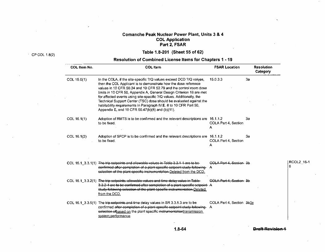
CP COL 1.8(2)
Comanche Peak Nuclear Power Plant, Units 3 & 4COL Application
Part 2, FSAR
Table 1.8-201 (Sheet 55 of 62)
Resolution of Combined License Items for Chapters 1 - 19
COL Item No. COL Item FSAR Location ResolutionCategory
COL 15.0(1) In the COLA, if the site-specific ?/Q values exceed DCD ?/Q values, 15.0.3.3then the COL Applicant is to demonstrate how the dose referencevalues in 10 CFR 50.34 and 10 CFR 52.79 and the control room doselimits in 10 CFR 50, Appendix A, General Design Criterion 19 are metfor affected events using site-specific ?/Q values. Additionally, theTechnical Support Center (TSC) dose should be evaluated against thehabitability requirements in Paragraph IV.E. 8 to 10 CFR Part 50,Appendix E, and 10 CFR 50.47(b)(8) and (b)(11).
3a
COL 16.1(1) Adoption of RMTS is to be confirmed and the relevant descriptions are 16.1.1.2 3ato be fixed. COLA Part 4, Section
A
COL 16.1(2) Adoption of SFCP is to be confirmed and the relevant descriptions are 16.1.1.2to be fixed. COLA Part 4, Section
A
3a
COL 16.1_3.3.1(1) The trip c .tpw•.. and allowal. ;Values 4n Table 3.3.1 1 arc to
COL 16.1_3.3.2(1)
confiPrmo~d aftorF %omplotion of a plant cpeeifie setpeint study followingcolcotien of thc plant spocific inotrumontatin.Deleted from the DCD.
The trip cctpointS, allowable Yaluoc and time delay :alue in Table-3.3.2 1 arc te be confirmoid aftcr eomplctien of a plant speeifie setpeintstudy fIellow'ng •o; .... tin •;of the plant specific inotrumontatin . Deletedfrom the DCD,
The trip cotpOintS and time delay values in SR 3.3.5.3 are to beconfirmed after ccmpletiRn of a plant . p..ific s.tpe.. t study followingseloee4et-efbased on the plant specific inotrumcnttiontransmissionsystem performance.
COLA Part 4, Scction 3bA
COLA Part 4, Scotin 36A
RCOL2_16-16
COL 16.1_3.3.5(1) COLA Part 4, Section 3b3aA
1.8-64 1.8-64 Draft Rc'.icion 4
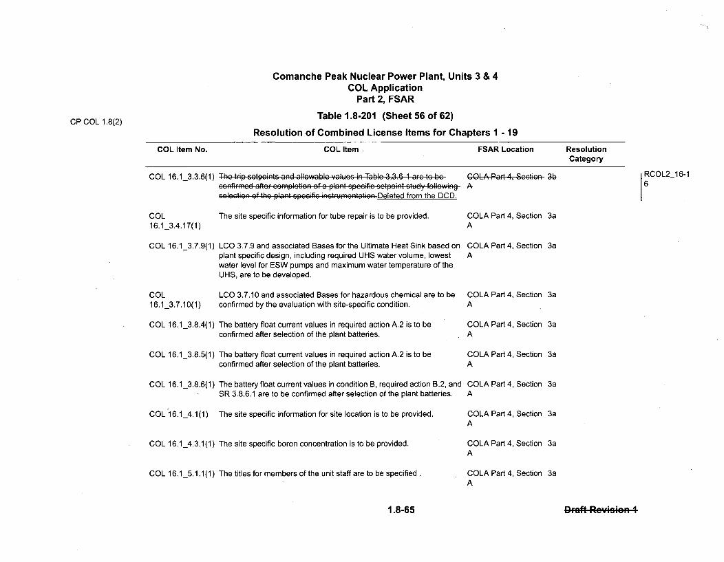
Comanche Peak Nuclear Power Plant, Units 3 & 4COL Application
Part 2, FSAR
CP COL 1.8(2) Table 1.8-201 (Sheet 56 of 62)
Resolution of Combined License Items for Chapters 1 - 19
COL Item No. COL Item FSAR Location ResolutionCategory
COL 16.1_3.3.6(1)
COL16.1_3.4.17(1)
COL 16.1_3.7.9(1)
COL16.1_3.7.10(1)
COL 16.1_3.8.4(1)
COL 16.1_3.8.5(1)
COL 16.1_3.8.6(1)
COL 16.1_4.1(1)
COL 16.1_4.3.1(1)
COL 16.1_5.1.1(1)
The trip , ,tp•irt. and allewable .lu.. . in Table 3.3.6 1 arc to becor44irmd aftor cWAmpltiGn of a plant Gp e"ifir c'tp' mt study fell owingslcti9R of the plant p,.cific inctrumon.tati-n. Deleted from the DCD.
The site specific information for tube repair is to be provided.
LCO 3.7.9 and associated Bases for the Ultimate Heat Sink based onplant specific design, including required UHS water volume, lowestwater level for ESW pumps and maximum water temperature of theUHS, are to be developed.
LCO 3.7.10 and associated Bases for hazardous chemical are to beconfirmed by the evaluation with site-specific condition.
The battery float current values in required action A.2 is to beconfirmed after selection of the plant batteries.
The battery float current values in required action A.2 is to beconfirmed after selection of the plant batteries.
The battery float current values in condition B, required action B.2, andSR 3.8.6.1 are to be confirmed after selection of the plant batteries.
The site specific information for site location is to be provided.
The site specific boron concentration is to be provided.
The titles for members of the unit staff are to be specified.
COLA Part 4, Seetien 3bA
RCOL2_16-16
COLA Part 4, SectionA
COLA Part 4, SectionA
COLA Part 4, SectionA
COLA Part 4, SectionA
COLA Part 4, SectionA
COLA Part 4, SectionA
COLA Part 4, SectionA
COLA Part 4, SectionA
COLA Part 4, SectionA
1.8-65 1.5Draft Rcveien 4

CP COL 1.8(2)
Comanche Peak Nuclear Power Plant, Units 3 & 4COL Application
Part 2, FSAR
Table 1.8-201 (Sheet 57 of 62)
Resolution of Combined License Items for Chapters 1 - 19
COL Item No. COL Item FSAR Location ResolutionCategory
COL 16.1_5.1.2(1) The titles for members of the unit staff are to be specified. COLA Part 4, Section 3aA
COL 16.1_5.2.1(1) The titles for members of the unit staff are to be specified. COLA Part 4, Section 3aA
COL 16.1_5.2.2(1) The titles and number for members of the unit staff are to be specified. COLA Part 4, Section 3aA
COL 16.1_5.3.1(1) Minimum qualification for unit staff is to be specified. COLA Part 4, Section 3aA
COL 16.1_5.5.1(1) The titles for members of the unit staff that approve the Offsite Dose COLA Part 4, Section 3aCalculation Manual are to be specified. A
COL 16.1_5.5.9(1) The site specific information for tube repair is to be provided. COLA Part 4, Section 3aA
COL Control Room Envelope Habitability Program for hazardous chemical COLA Part 4, Section 3a16.1_5.5.20(1) are to be confirmed by the evaluation with site-specific condition. A
COL NRC aporoved setooint methodology is to be referred in the Setpoint COLA Part 4. Section 3b16.1 5.5.21(1) Control Program. A
COL 16.1_5.6.1(1) In case of multiple unit site, the additional information for submittal of COLA Part 4, Section 3areport is to be added. A
COL 16.1_5.6.1(2) The format of the Annual Radiological Environmental Operating COLA Part 4, Section 3aReport is to be specified based on "the format of the table in the ARadiological Assessment Branch Technical Position, Revision 1,November 1979" or another format.
RCOL2_16-16
1.8-66 1.86Draft R oViRmio 4
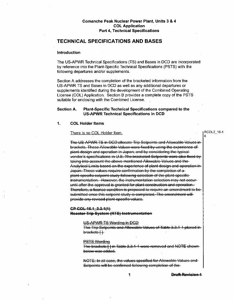
Comanche Peak Nuclear Power Plant, Units 3 & 4COL Application
Part 4, Technical Specifications
TECHNICAL SPECIFICATIONS AND BASES
Introduction
The US-APWR Technical Specifications (TS) and Bases in DCD are incorporatedby reference into the Plant-Specific Technical Specifications (PSTS) with thefollowing departures and/or supplements.
Section A addresses the completion of the bracketed information from theUS-APWR TS and Bases in DCD as well as any additional departures orsupplements identified during the development of the Combined OperatingLicense (COL) Application. Section B provides a complete copy of the PSTSsuitable for enclosing with the Combined License.
Section A. Plant-Specific Technical Specifications compared to theUS-APWR Technical Specifications in DCD
1. COL Holder Items
There is no COL Holder Item. RCOL2_16-16
The US APWR T-8 in DCGD allocate Trip Setpoints and Allowablc Valucs ibraekets. These Allowablc Values~ re~ fixed by usinth zxsinee cfplant design and epcratio n Japan, and by .. nsidcing the typioYender'S spccifications in U.S. The brackcted Setpoints wero also filxcd by
taking into account the above mentiencd Allowablc Values and theAnalytical Limits based on the experienee of plant design and operation iJapan. These Yalucs roguirc conAfirmnation by the completion of a-plant sp..ifie s÷tp•o•t study following s.lc.tioRnef the plant sp...-'sVinStrumcntation. Howcvcr-, the ntunctto scleotion may not occuruntil aftor the approval is gran ted forF plant conrucHtion and OperatiOn.Thcrcforc, a liconoc condition is prOposed to rogu1Fo an amondmont to besubmibtted oncs this setpoint study as complcted. The amend~mon~t lnr,,idc any r. i.s. d pl ant spc1ifiG c alus. .I
C" COLl 46.4_3.3.4()1ReaOtO. T.ip Systcm 'FITS) InItrIumIntatiI
I IL' ADi AID TO IAI,..4;-- ;- r1-%r'i
The Tr'Fip S1tpoi'ts _and- Allo.wab.l...i 1 Values of Table 3.3.1 1 p•Ja•d inb~aek~ets-f
The brackcets [inTable 3.3.1 1 wsrc romovod and NOTE shown
bolow was addcd.
NOTE& In all ease, the valucs speecificd for Allowable Values and
•,1÷ 4. x
eaý etpeints will be GeRtIF A fullewing
I W Draft Revision I

Comanche Peak Nuclear Power Plant, Units 3 & 4COL Application
Part 4, Technical Specifications
plant spc;ifi- sctpof÷int study. These values will be calculated inaccordanec with the setpoint methodology aftcr selcetien ofplant SPccifeicintrumcnetatiOnc.
406~tif4RTable 3.3.1 1 ruiccofirmation ef the trip sctpeint andallowabice vaalucs by the ccmplction of a plant specific setpoint-study following selectien of the plant spec t nHeo•ver, thein s.trumentation see.ti-n may not occur untoi aftcrthe approlval iS grantcd for plant construction and operation.Therefors, a license condition is proposcd to roguire anamclndmcnt to be submitted onee this setpcint study is completcdThe amcndmcent will prcVidc an" rovised plant specific values.
CG PG0Ol 16.1 _3.3.2 .(1)renainreeod Safei: FeaWuroP ActuiatiaR System (ESFAS!
RCOL2_16-16
InstUmcntaieon
US'P APWA T-S IWsrMinA in W=
The TrFip Setpkintc and Allowablc ValueG of Table 3.3.2 1 placed ibffleketG [H]
The brackets ]i Table 3.3.2 1 were rcmovced and NOTE shownbclew was added.
NOTE. In all ease, the values specified for Allowable Values andgetpe:n• wi;ll W"be cf:rmed following em pl:etin of the
plant spccifie setpoint study. These values will be ealulat-d in
asso rdan cc with the etp oint mnethodology after seleotion ofplant Gpceifie instrumF~entations,.
Table 3.3.2 1 rcquircs confirmfation of the trip setpefint andallowable valucs by the comnpletion of a plant speeifi etonstudy following seleetion of the plant specific ntucnainHowcvcr, the 4nstFHFmcntatien scleetion Ma" nat occur until afterthe approval is grnted for plant construction and epefration.-T-heefoa lcne endfition is PEpropsed to require anamendmfent to be submitted once this setpkint study is completedThe amcndment will provide any revised plant speeific values.
Cr Ct=l 446.43.3.5(4)Loss of PIw (1LOP2) Glass I-; Gas uRw-I-lnStrUmcntnationf
1 12 APIAR T-2 Wprplipt, in Q=~f
ucncato (U I~ • | Jil,
The NeFnifnal Trip Setpoints of SR 3.3.6.3 placcd in BIaelIe" ff
2 2 raft•, Re-ision I
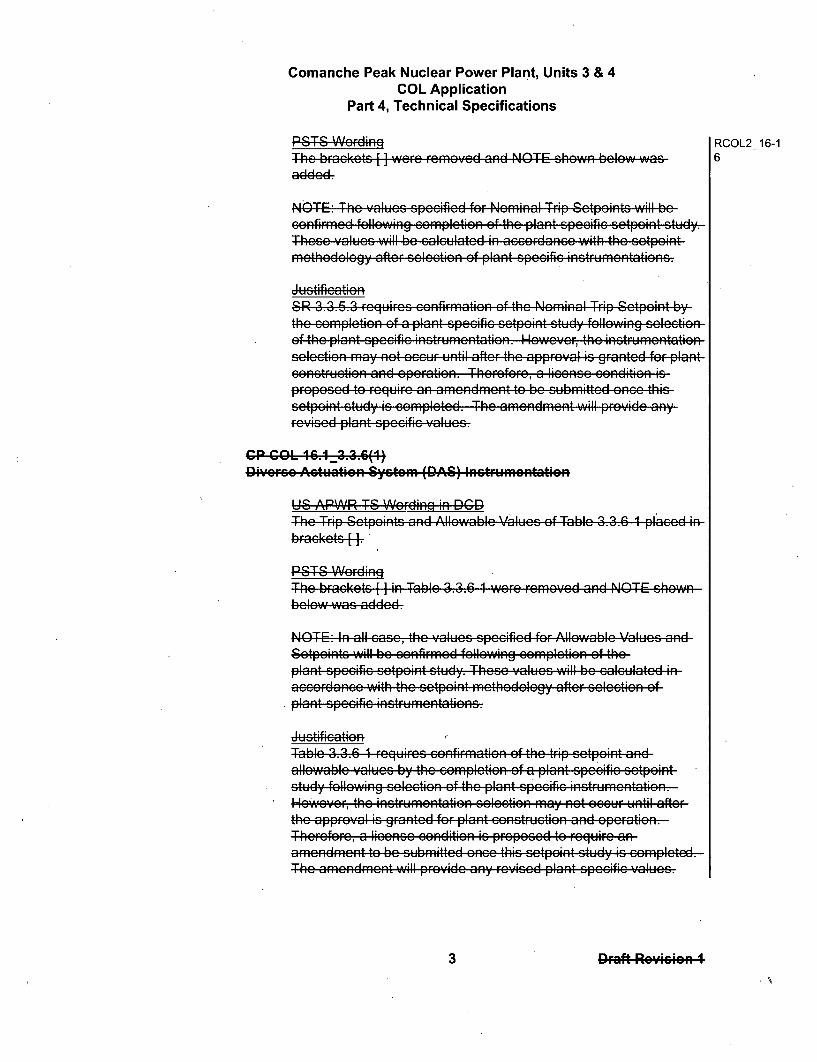
Comanche Peak Nuclear Power Plant, Units 3 & 4COL Application
Part 4, Technical Specifications
The bFaekets+~added.
RCOL2_16-16wero rcmovcd and NOTE shown bclow was
NO1 .TE-. The values spe;ifi"d for N ;minal Trip S -tpoints will beoRnfirm•d follwing completion of the plant spc-ifi; sctpeint stuy-,
Theso valucs MIl be calculated in accordlanco with the sctpointmcethodelogy after selcction of plant Spccifie inStrumentations.
SIR 3.3.5.3 rcguircs 68onfirmation of the Nominal TriOp Sctpoint by-the completion of a plant specific ..pon . tudy following selectionof the plant spccific inStRumcntation. Howevor-, the On~tru rnntationselection mfay not occur unti after the approVal is gra~nted for Plantcons1:1trucio and opcraition. Theroforo, a licenso conditicn isffproocd to roguiro an amendment to be cubhpmittd once thicsetpeint study is completed. The amendment will pro. de anyrovised plant specific values.
crc A ui is( D )lvruc t
I IU ADIAID T-8 1A/,..-.-4;E OFý . I-rr
The TrFip Setpeints -And Al .I11Ab.l-RIe Val-e-s of. Ta ble 3.3.6 1 lcdibFaekets±1
The b•rekets [- in Table 3.3.6 1 Were removed and NOTE shown
below was added.
NOTE& In all ase, the values spe"'ifid for Allwable- Values anv
Setpoints will be onfirm1ed following completion of theplant specific setpein~t stud". These values will be calcuilated iaccordance with the setp'int m,,thde-lgy aftir selection ofplant specific instruntdt-n..a
Table 3.3.6 1 requires confirmnation of the trip sctpoint anidallowable valucs by the complction of a plant specific setponstudy following colection of the plant speifi inetrumentation.However, the insGtrumentation selection May not occur until afterthe approvYal OS franted fr pln construction and epefration.Thercforc, a license eendktin_ is proposed to r.ur anamendment to be submitted once this sctpoint study is completedThe aAmenRdment will prcvidc Iny revised plant specific aus
3 3 -Draft- Rc-icion 4
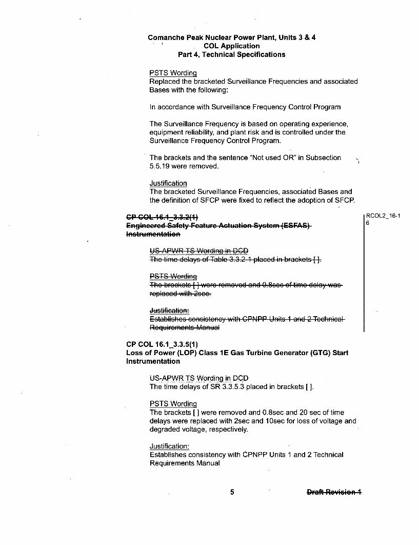
Comanche Peak Nuclear Power Plant, Units 3 & 4COL Application
Part 4, Technical Specifications
PSTS WordingReplaced the bracketed Surveillance Frequencies and associatedBases with the following:
In accordance with Surveillance Frequency Control Program
The Surveillance Frequency is based on operating experience,equipment reliability, and plant risk and is controlled under theSurveillance Frequency Control Program.
The brackets and the sentence "Not used OR" in Subsection5.5.19 were removed.
JustificationThe bracketed Surveillance Frequencies, associated Bases andthe definition of SFCP were fixed to reflect the adoption of SFCP.
Cr COLn ,3I"3.2(1) RCOL2_16-1Enginccrcd Safcty; FAurc; A;tuation Syst• m (ESFAS) 6
US1 ADRAID T-6 V1AI.-n-. in~ IDGD
The time delays of Table 3.3.2 1 plaeed in braekcts [I.
The bFrekets [ I wer rFeme.d and 0.8sI' of time delay wasrcplaeed with 2see.
Establishcs consistcncy with CPNPP Units 1 and 2 TechnicalRcquircmcnts Manual
CP COL 16.1_3.3.5(1)Loss of Power (LOP) Class 1 E Gas Turbine Generator (GTG) StartInstrumentation
US-APWR TS Wording in DCDThe time delays of SR 3.3.5.3 placed in brackets [].
PSTS WordingThe brackets [ ] were removed and 0.8sec and 20 sec of timedelays were replaced with 2sec and .Osec for loss of voltage anddegraded voltage, respectively.
Justification:Establishes consistency with CPNPP Units 1 and 2 TechnicalRequirements Manual
5 5 Draft Rc•mvmo I

Comanche Peak Nuclear Power Plant, Units 3 & 4COL Application
Part 4, Technical Specifications
The purpose of loss of voltage protection is to protect voltage RCOL2_16-1sensitive loads, such as motors, whenever the bus voltage drops 5below the acceptable value. For equipment protection, only a shorttime is allowed to give the grid a chance to recover. Since thetransmission system for Units 3 and 4 is provided by the sameTransmission Service Provider and associated with the samepower pool as Units 1 and 2, the setting of loss of voltageprotection of Units 1 and 2 was duplicated.
The purpose of degraded voltage protection is to assure that theplant equipment is not impacted by voltage degradation in the localarid (no faults present). Therefore a longer time is allowed to givethe grid a chance to recover. Since all Comanche Peak Units areequipped with similar plant equipment, the setting of degradedvoltage protection of Units 1 and 2 was duplicated.
CP COL 16.1_3.4.17(1)Steam Generator (SG) Tube Integrity
US-APWR TS Wording in DCDLCO 3.4.17 and associated Bases discuss steam generator tuberepairs in [ ].
PSTS WordingThe discussion of steam generator tube repairs specified in []wasdeleted from LCO 3.4.17 and associated Bases.
JustificationEstablishes consistency with changes to "5.5.9 Steam Generator(SG) Program".
CP COL 16.1_3.7.9(1)Ultimate Heat Sink
US-APWR TS Wording in DCDThe bracketed information in LCO 3.7.9 of the US-APWR TSreads:3.7.9 Ultimate Heat Sink (UHS)[Not applicable to US-APWR Design Certification. Site-specificinformation to be provided by COL Applicant.]
The bracketed information in B 3.7.9 of the US-APWR TS reads:B 3.7.9 Ultimate Heat Sink (UHS)[Not applicable to US-APWR Design Certification. Site-specificinformation to be provided by COL Applicant.]
6 6 Draft Reyesion 1

Comanche Peak Nuclear Power Plant, Units 3 & 4COL Application
Part 4, Technical Specifications
CP COL 16.1_5.5.20(1)Control Room Envelope Habitability Program
US-APWR TS Wording in DCDThe bracketed information in Section 5.5.20.c of the US-APWR TSreads:[The following are exceptions to Sections C.1 and C.2 ofRegulatory Guide 1.197, Revision 0:1. ;and]PSTS WordingReplace the bracketed information in Section 5.5.20 of theUS-APWR TS with the following:The following are exceptions to Sections C.1 ard C.2 of RegulatoryGuide 1.197, Revision 0:
1. C. - Section 4.3.2 "Periodic CRH Assessment" from NEI99-03 Revision 1 will be used as input to a site-specificSelf-Assessment procedure.
2. C.1.2 - No peer reviews are required to be performed.
Justification:Establishes consistency with CPNPP Units 1 and 2 TechnicalSpecifications.
.CP COL 16.1 5.5.21(1) RCOL2_16-1Setpoint Control Program Methodology and Implementation 6
US-APWR TS Wording in DCDUS-APWR TS Section 5.5.21 includes bracketed references to theapproved US-APWR Instrument Setpoint Methodology revisionand the corresponding NRC Safety Evaluation date, as well asapplicable ADAMS accession number.
PSTS Wording
The approved US-APWR Instrument Setpoint Methodologyrevision and corresponding NRC Safety Evaluation date, aswell asapplicable ADAMS accession number will be provided in asubsequent submittal to complete these brackets.
JustificationNRC approval of US-APWR Instrument Setpoint Methodology ispending.
CP SUP 16.1_5.5.24-22(1)Technical Requirements Manual (TRM)
I
14 14rDaft R.c-v••c..
Comanche Peak Nuclear Power Plant, Units 3 & 4COL Application
Part 4, Technical Specifications
US-APWR TS Wording in DCDThe US-APWR TS does not include an Administrative Control forthe Technical Requirements Manual.
PSTS WordingAdministrative Control 5.5.2422 was added for the Technical 6 OL216-1
Requirements Manual. 6
Justification:Establishes consistency with CPNPP Units 1 and 2 TechnicalSpecifications.
CP COL 16.1_5.6.1(1)Annual Radiological Environmental Operating Report
US-APWR TS Wording in DCDIn Section 5.6.1, the US-APWR TS does not include any notes.
PSTS Wording
In Section 5.6.1, a Note was added that states:
-----------------NOTE ---------------------
A single submittal may be made for a multiple unit station. Thesubmittal should combine sections common to all units at thestation.
Justification:Establishes consistency with CPNPP Units land 2 TechnicalSpecifications and addresses a two-unit site.
CP COL 16.1_5.6.1(2)Annual Radiological Environmental Operating Report
US-APWR TS Wording in DCDThe bracketed information in Section 5.6.1 of the US-APWR TSreads:The Annual Radiological Environmental Operating Report shallinclude the results of analyses of all radiological environmentalsamples and of all environmental radiation measurements takenduring the period pursuant to the locations specified in the tableand figures in the ODCM, as well as summarized and tabulatedresults of these analyses and measurements [in the format of the
15 15 Draft RcuiWvn I

Definitions1.1
1.1 Definitionsf
CHANNEL CALIBRATION A CHANNEL CALIBRATION shall be the adjustment, asnecessary, of the channel output such that it responds withinthe necessary range and accuracy to known values of theparameter that the channel monitors. The CHANNELCALIBRATION shall encompass all devices in the channelrequired for channel OPERABILITY. CHANNELCALIBRATION encompasses devices that are subject to driftbetween surveillance intervals and all input devices that arenot tested through continuous automated self-testing. Referto TADOT for output devices that are not tested throughcontinuous automated self-testing.
The performance of a CHANNEL CALIBRATION shall beconsistent with specification 5.5.2.1, "Setpoint ControlProgram" (SCP).
For analog measurements on each Technical Specificationrequired automatic protection instrumentation functionimplemented with a digital bistable function, the CHANNELCALIBRATION confirms the accuracy of the channel fromsensor to digital Visual Display Unit (VDU) readout, asdescribed in Topical Report, "Safety I&C System Descriptionand Design Process," MUAP-07004 Section 4.4.2.CHANNEL CALIBRATION confirms Ihe analog measurementaccuracy at five calibration setpkn4tssetting, correspondingto 0%, 25%, 50%, 75% and 100% of the instrument range.
For analog measurements on each Technical Specificationrequired automatic protection instrumentation functionimplemented with analog bistable function, the CHANNELCALIBRATION confirms the accuracy of the channel fromsensor to output device. For these channels, CHANNELCALIBRATION confirms the analog measurement accuracyat the Nominal Trip Setpoint (NTSP).
For binary measurements, the CHANNEL CALIBRATIONconfirms the accuracy of the channel's state change, asdescribed in Topical Report, "Safety I&C System Descriptionand Design Process," MUAP-07004 Section 4.4.21.
Calibration of instrument channels with resistancetemperature detector (RTD) or thermocouple sensors mayconsist of an inplace qualitative assessment of sensorbehavior and normal calibration of the remaining adjustabledevices in the channel. The CHANNEL CALIBRATION maybe performed by means of any series of sequential,overlapping, or total channel steps.
RCOL2_16-16
RCOL2_16-16
I
COMANCHE PEAK - UNITS 3 AND 4 1.1-2 Re~e*~-OCOMANCHE PEAK - UNITS 3 AND 4 1.1-2 Rcvislcn 0
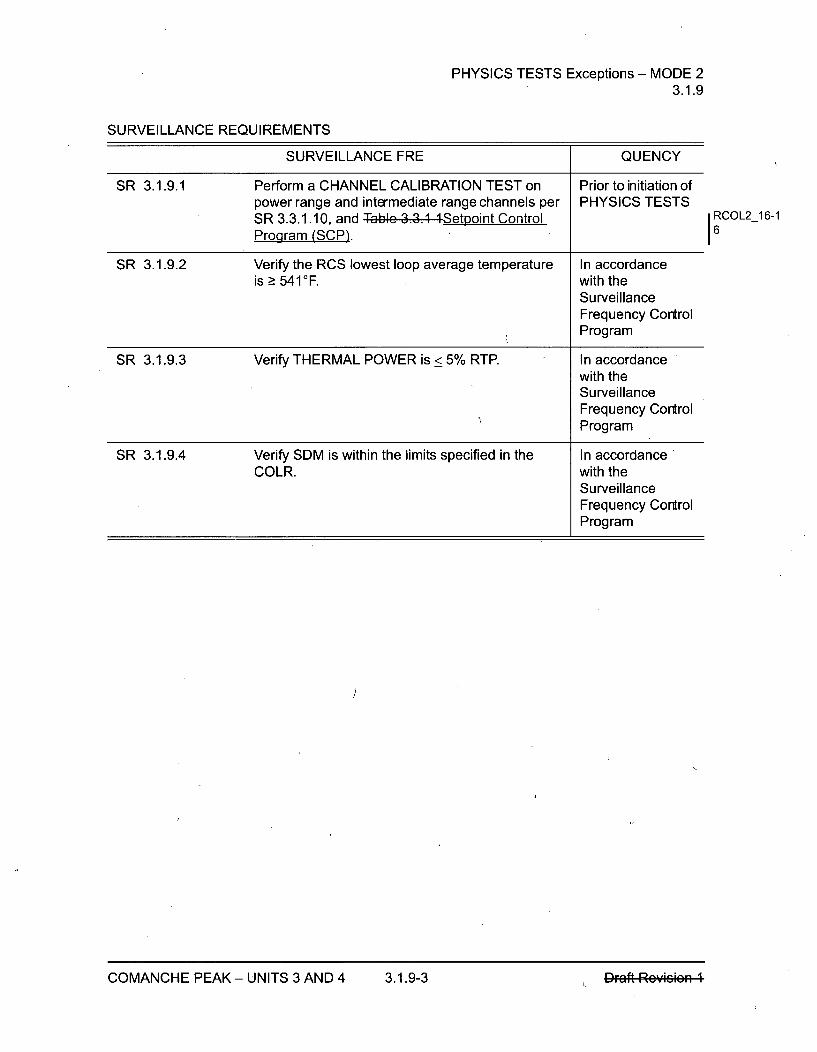
PHYSICS TESTS Exceptions - MODE 23.1.9
SURVEILLANCE REQUIREMENTS
SURVEILLANCE FRE QUENCY
SR 3.1.9.1 Perform a CHANNEL CALIBRATION TEST on Prior to initiation ofpower range and intermediate range channels per PHYSICS TESTSSR 3.3.1.10, and Table 3.3.1 ISetpoint ControlProgram (SCP).
SR 3.1.9.2 Verify the RCS lowest loop average temperature In accordanceis > 541OF. with the
SurveillanceFrequency ControlProgram
SR 3.1.9.3 Verify THERMAL POWER is < 5% RTP. In accordancewith theSurveillanceFrequency ControlProgram
SR 3.1.9.4 Verify SDM is within the limits specified in the In accordanceCOLR. with the
SurveillanceFrequency ControlProgram
I RCOL2_16-16
COMANCHE PEAK - UNITS 3 AND 4 3.1.9-3 DFaft Reymsm
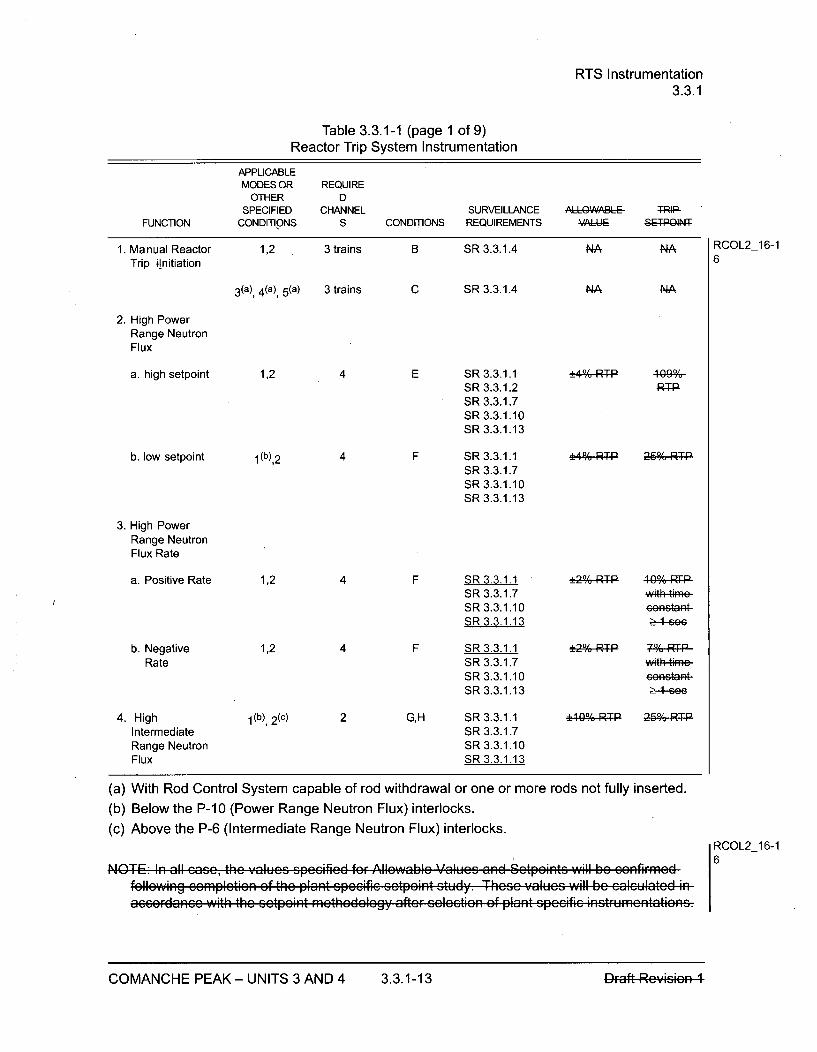
RTS Instrumentation3.3.1
Table 3.3.1-1 (page 1 of 9)Reactor Trip System Instrumentation
APPLICABLEMODES OR REQUIRE
OTHER DSPECIFIED CHANNEL SURVEILLANCE Al",LQWARLE TRI-
FUNCTION CONDITIONS S CONDITIONS REQUIREMENTS I
1. Manual Reactor 1,2 3 trains B SR 3.3.1.4 NA NATrip ,Initiation
RCOL2_16-16
3(a), 4(a), 5(a) 3 trains C SR 3.3.1.4 NA NA
2. High PowerRange NeutronFlux
a. high setpoint 1,2 4 E SR 3.3.1.1SR 3.3.1.2SR 3.3.1.7SR 3.3.1.10SR 3.3.1.13
F SR 3.3.1.1SR 3.3.1.7SR 3.3.1.10SR 3.3.1.13
_ 0 RT-TP 260,;RT-b. low setpoint 4
3. High PowerRange NeutronFlux Rate
a. Positive Rate
b. NegativeRate
4. HighIntermediateRange NeutronFlux
1,2
1,2
4
4
F SR 3.3.1.1SR 3.3.1.7SR 3.3.1.10SR 3.3.1.13
F SR 3.3.1.1SR 3.3.1.7SR 3.3.1.10SR 3.3.1.13
!E29% RT-P 119,% WP
eeGRtaR-
with fime-
e-4-see
00% -R- 26%RT-P1(b), 2(c) 2 G,H SR 3.3.1.1
SR 3.3.1.7SR 3.3.1.10SR 3.3.1.13
(a) With Rod Control System capable of rod withdrawal or one or more rods not fully inserted.
(b) Below the P-10 (Power Range Neutron Flux) interlocks.
(c) Above the P-6 (Intermediate Range Neutron Flux) interlocks.
tC) I 1< In all rcn.qc thin w~li-c sncizerlpt fF II ? -I-j ... 7 ý- ý - - V-- -.-
OF Allowablc Values and Setpeints will be cAnfirmoedeifie setpeint stu dy. These Y alucs will be calculated in
RCOL2_16-16
TolloWIng COFAPIC1IGOfl 01e pn ~lan spcau 8uuuruun Witri t[he SetPGIRii [I1ULIUUUIy afteF ZsCIeCLIUI 9t piuiit upeuItI IFIu ;r;:..;r;
COMANCHE PEAK - UNITS 3 AND 4 3.3.1-13 Draft Rcvk~ion 1COMANCHE PEAK - UNITS 3 AND 4 3.3.1-13 PFaft Reyms*eFi 1

RTS Instrumentation3.3.1
Table 3.3. 1-1 (page 2 of 9),Reactor Trip System Instrumentation
APPLICABLEMODES OR
OTHERSPECIFIED
CONDITIONSREQUIREDCHANNELS
SURVEILLANCE A''L WARL-REQUIREMENTS VAL-EFUNCTION CONDITIONS
5. High SourceRange NeutronFlux
2 (d) 2 I,J SR 3.3.1.7SR 3.3.1.8SR 3.3.1.10SR 3.3.1.13
t%-eofepaA !.()4EGPS
3(a), 4(a), 5(a) 2 J,K SR 3.3.1.1SR 3.3.1.7SR 3.3.1.10SR 3.3.1.13
1.0 E+50199
6. Overtempera-ture AT
1,2 3 F SR 3.3.1.1SR 3.3.1.3SR 3.3.1.6SR 3.3.1.7SR 3.3.1.11SR 3.3.1.13
RefeF-4-hPlee-4afteF
this table
Refe-ke-Nete-1
afteFrthiztable
(a) With Rod Control System capable of rod withdrawal or one or more rods not fully inserted.
(d) Below the P-6 (Intermediate Range Neutron Flux) interlocks.
COMANCHE PEAK - UNITS 3 AND 4 3.3.1-14 P~aft Rey,4ei =,-1-
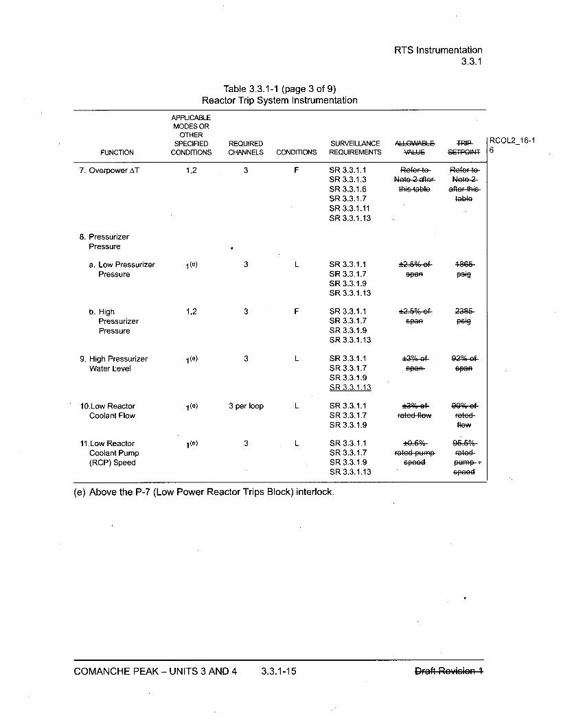
RTS Instrumentation3.3.1
Table 3.3.1-1 (page 3 of 9)Reactor Trip System Instrumentation
APPLICABLEMODES OR
OTHERSPECIFIED REQUIRED SURVEILLANCE 4 W T RCOL2_16-1
FUNCTION CONDITIONS CHANNELS CONDITIONS REQUIREMENTS V4IIUI 5IPGIAI 6
7. Overpower AT 1,2 3 F SR 3.3.1.1 Refe-t8e- Refe--te-SR 3.3.1.3 .eWtc 2 e Br Nete---
SR 3.3.1.6 t-hs-table afteFrthS-SR 3.3.1.7SR 3.3.1.11SR 3.3.1.13
8. PressurizerPressure
a. Low Pressurizer 1(e) 3 L SR 3.3.1.1 +2.60;ef 4866-Pressure SR 3.3.1.7 spao
SR 3.3.1.9SR 3.3.1.13
b. High 1,2 3 F SR 3.3.1.1 +2.60%-e- 23-86Pressurizer SR 3.3.1.7 span
Pressure SR 3.3.1.9SR 3.3.1.13
9. High Pressurizer 1(e) 3 L SR 3.3.1.1 +,;e- 92-%-e0-Water Level SR 3.3.1.7 PaA sa-
SR 3.3.1.9SR 3.3.1.13
1O.Low Reactor l(e) 3 per loop L SR 3.3.1.1 +3%;ef 0"; efCoolant Flow SR 3.3.1.7 Fated flew Fated
SR 3.3.1.9 flew
11.Low Reactor 1(e) 3 L SR 3.3.1.1 !Coolant Pump SR 3.3.1.7 Fated pump F-aeted(RCP) Speed SR 3.3.1.9 speed FRf
SR 3.3.1.13 speed
(e) Above the P-7 (Low Power Reactor Trips Block) interlock.
COMANCHE PEAK - UNITS 3 AND 4 3.3.1-15 DFaft Rey*rm

RTS Instrumentation3.3.1
Table 3.3.1 -1 (page 4 of 9)Reactor Trip System Instrumentation
APPLICABLEMODES OR
OTHER SPECIFIED. CONDITIONS
REQUIREDCHANNELS
SURVEILLANCECONDITIONS REQUIREMENTS
A' I VQu)ARIAI :r-Re- RCOL2_16-1
SL•-plagN 6FUNCTION
12.SteamGenerator (SG)Water Level
a. Low 1,2 3 per SG
3 per SGb. High-High 1(e)
F SR 3.3.1.1SR 3.3.1.7SR 3.3.1.9SR 3.3.1.13
L SR 3.3.1.1SR 3.3.1.7SR 3.3.1.9SR 3.3.1.13
L SR 3.3.1.1SR 3.3.1.7SR 3.3.1.9SR 3.3.1.12
LT SR 3.3.1.9SR 3.3.1.12
±30,;-ef 13,;3 Of
spea span
°3T3f 7o,-ef-epf~q fm
13. Turbine Trip
a. TurbineEmergencyTrip OilPressure
b. Main TurbineStop ValvePosition
1 (e) 3 Ž- 930 peio 4000 psig
1(e) 1 pervalve
(e) Above the P-7 (Low Power Reactor Trips Block) interlock.
COMANCHE PEAK - UNITS 3 AND 4 3.3.1-16
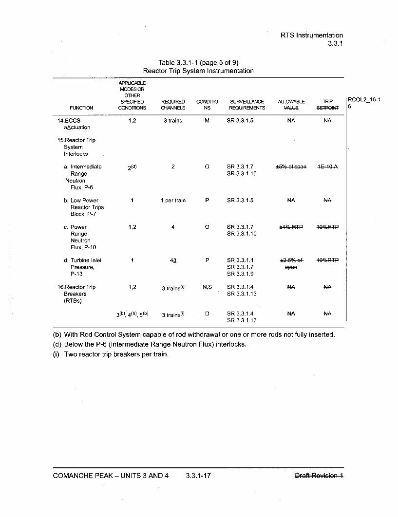
RTS Instrumentation3.3.1
Table 3.3.1-1 (page 5 of 9)Reactor Trip System Instrumentation
APPLICABLEMODES OR
OTHERSPECIFIED REQUIRED CONDITIO SURVEILLANCE ,A&l A- TRIP-
FUNCTION CONDITIONS CHANNELS NS REQUIREMENTS - ,E-PQIAIN
14.ECCS 1,2 3 trains M SR 3.3.1.5 NA NAaActuation
15.Reactor TripSystemInterlocks
a. Intermediate 2 (d) 2 0 SR 3.3.1.7 +5% of spa E ARange SR 3.3.1.10
NeutronFlux, P-6
b. Low Power 1 1 per train P SR 3.3.1.5 NA NAReactor TripsBlock, P-7
c. Power 1,2 4 0 SR 3.3.1.7 _4-%-RP, T-P 4RPRange SR 3.3.1.10NeutronFlux, P-10
d. Turbine Inlet 1 43 P SR 3.3.1.1 !25.60e- 40-07R-T-Pressure, SR 3.3.1.7 spaP-13 SR 3.3.1.9
16.Reactor Trip 1,2 3 trains(') N,S SR 3.3.1.4 NA NABreakers SR 3.3.1.13(RTBs)
3 (b), 4 (b), 5 (b) 3 trains(') D SR 3.3.1.4 NA NASR 3.3.1.13
(b) With Rod Control System capable of rod withdrawal or one or more rods not fully inserted.(d) Below the P-6 (Intermediate Range Neutron Flux) interlocks.(i) Two reactor trip breakers per train.
RCOL2_16-16
COMANCHE PEAK - UNITS 3 AND 4 3.3.1-17 Draft Rcvision 1COMANCHE PEAK - UNITS 3 AND 4 3.3.1-17

RTS Instrumentation3.3.1
Table 3.3.1-1 (page 6 of 9)Reactor Trip System Instrumentation
APPLICABLEMODES OR
OTHERSPECIFIED REQUIRED SURVEILLANCE ALUW.A•IE P TRIP-
FUNCTION CONDITIONS CHANNELS CONDITIONS REQUIREMENTS 9- FE12Q11
17.Reactor Trip 1,2 3 trains QS SR 3.3.1.4 NA NABreaker 1 each per SR 3.3.1.13Undervoltage RTBand ShuntTrip 3 (b), 4 (b), 5 (b) 3 trains D SR 3.3.1.4 NA NAMechanisms 1 each per SR 3.3.1.13
RTB
18.Automatic 1,2 3 trains R,S SR 3.3.1.5 NA NATrip Logic
3 (b), 4 (b), 5 (b) 3 trains D SR 3.3.1.5 NA NA
(b) With Rod Control System capable of rod withdrawal or one or more rods not fully inserted.
RCOL2_16-16
COMANCHE PEAK - UNITS 3 AND 4 3.3.1-18
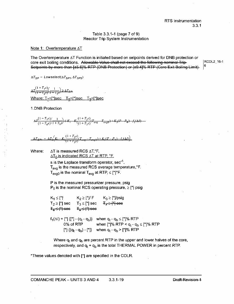
RTS Instrumentation3.3.1
Table 3.3.1-1 (page 7 of 9)Reactor Trip System Instrumentation
Note 1: Overtemperature AT
The Overtemperature AT Function is initiated based on setpoints derived for DNB protection orcore exit boiling conditions. Allowablc Valuc shall not cxcccd the following nominal Trip RCOL2_16-1Sctpeintc b3Y marc than [:E5.610, RTP ([DNB Protcctien) or [±ý9.4-17 RT-P (Corc Exit Boiling Limit)6
ATSp =Lowse/ect(ATSP1, ATSP2)
(TI + TTS) I > ATkI 1 '8s)\1 •- 19s7/
Where: T7=[*]sec T8=f*lsec Tg=-Icsec
1.DNB Protection
0, + TO ,+ 9)- 1 TS)
AT. ( + T2s)ATsi±7}I = K1 -( 1 .g ±- 3 )Tv Tav.p) + K 3(P P 0)- f, (Ai J
A7'S,-j 4 T(KiK~ -& (T,,-T,,,)+K,(P-P.)f(I- k I 1 3 s ) . - I
Where: AT is measured RCS AT,0F.ATo is indicated RCS AT at RTR OF.
s is the Laplace transform operator, sec 1 .Tavg is the measured RCS average temperature,*F.Tavgo is the nominal Tavg at RTP, < [*]OF.
P is the measured pressurizer pressure, psigP0 is the nominal RCS operating pressure, > [*] psig
K1 , [*] K2 > [*]/F K3 > [*]/psigT2 [*]sec T3 <[*]sec aŽ+.re,
s8{~ee 1-•!5 Beee
fj(AI) =[*] {[*] - (qt - qb)} when qt - qb<[*]% RTP0% of RTP when [*]% RTP < qt - qb! < [*]% RTP[*] {(qt - qb) - [*]} when qt - qb > [*]% RTP
Where qt and qb are percent RTP in the upper and lower halves of the core,respectively, and qt + qb is the total THERMAL POWER in percent RTP.
*These values denoted with [*] are specified in the COLR.
COMANCHE PEAK - UNITS 3 AND 4 3.3.1-19 Draft Rcvizion ICOMANCHE PEAK - UNITS 3 AND 4 3.3.1-19 DFaft Reymsm
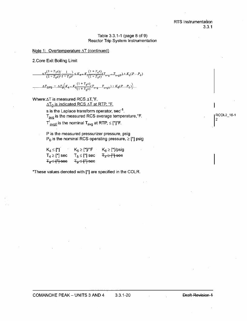
RTS Instrumentation3.3.1
Table 3.3.1-1 (page 8 of 9)Reactor Trip System Instrumentation
Note 1: Overtemperature AT (continued)
2.Core Exit Boiling Limit
(1+T 7 s) 1 "\< (I + T 4 s)__ _ATX I--'"'- I---K 4=JKs • (-T-ag•T-vgO.)-+K 6 (P--.?-O-)
(1 + T8s) i--+ T9s/ (l1+±T '5 s) ° J
-AT pý AT ( 4 -K (I + T4s) ( .g .,g - + "•--O-)
Where:AT is measured RCS ATF.ATo is indicated RCS AT at RTP, OF.
s is the Laplace transform operator, sec-1 .T-ava is the measured RCS average temperature,*F.
T-avpo is the nominal Tavg at RTP, < [*]OF.
IRCOL2_16-12
P is the measured pressurizer pressure, psigP0 is the nominal RCS operating pressure, __ [*] psig
K4 < [*] K5 > [*]/OFT4 [*]sec T5<[* sec
T - J• Lsee I !ýsee
K6 > [*]/psig
*These values denoted with [*] are specified in the COLR.
COMANCHE PEAK - UNITS 3 AND 4 3.3.1-20 Draft Rc',,sieln I
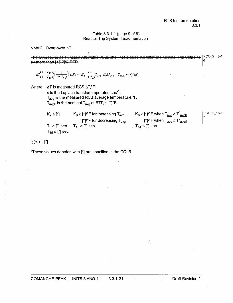
RTS Instrumentation3.3.1
Table 3.3.1-1 (page 9 of 9)Reactor Trip System Instrumentation
Note 2: Overpower AT
The OvcrFpGWcrAT- Functiaireby mor8e than [!E6.21], RTPFk
i i i II l
i :~iiowaoic vaiuc snail not c~cco ins ioiiawina naminai i rio ~CtDOIflt RCOL2_16-16
+___ )( _______( T 6sA T(7"1s)y + T1 5 -s - K 7 + -K 8 1 + ,Tavg-K9(Tavg - Tavgo) -f 2(AI)
Where: AT is measured RCS AT,°F.
s is the Laplace transform operator, sec1 .Tavg is the measured RCS average temperature,0 F.
Tavgo is the nominal Tavg at RTP, _< [*]*F.
K7 < [*] K8 _ [*]/OF for increasing Tavg[*]/OF for decreasing Tavg
K9 > [*]/OF when Tav. > T-av•_o[*]/OF when Tav_•< T-avo
T14 _< [*] sec
RCOL2_16-12
T6 > [*] sec T1 3 > [*] sec
T1 5 < [*] sec
f2 (AI) = [*]
*These values denoted with [*] are specified in the COLR.
COMANCHE PEAK - UNITS 3 AND 4 3.3.1-21 Draft Rovicion ICOMANCHE PEAK - UNITS 3 AND 4 3.3.1-21 I•r-•ff D,-,•,;•--;,-,• 4
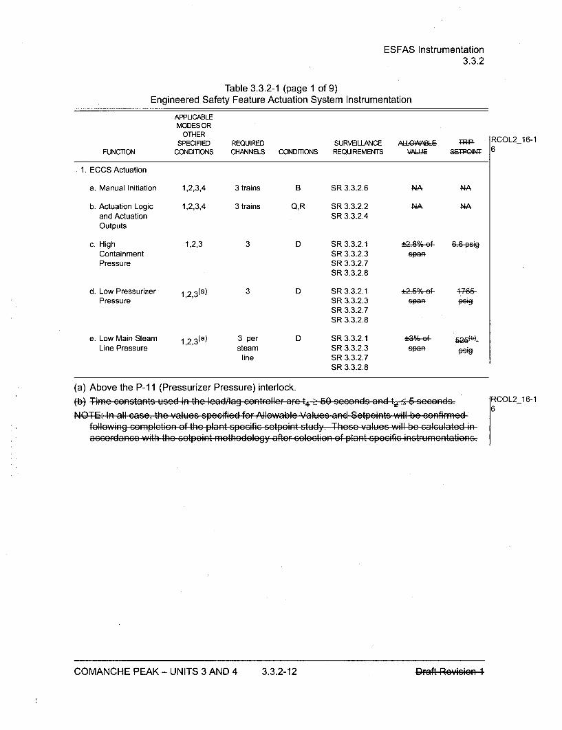
ESFAS Instrumentation3.3.2
Table 3.3.2-1 (page 1 of 9)Engineered Safety Feature Actuation System Instrumentation
APPUCABLEMODES OR
OTHER
SPECIFIED REQUIRED SURVEILLANCE ALOW BLE RCOL2_16-1
FUNCTION CONDITONS CHANNELS CONDITONS REQUIREMENTS \A14J= S 6
1. ECCS Actuation
a. Manual Initiation 1,2,3,4 3 trains B SIR 3.3.2.6 NA NA
b. Actuation Logic 1,2,3,4 3 trains Q,R SR 3.3.2.2 NA NAand Actuation SR 3.3.2.4Outputs
c. High 1,2,3 3 D SIR 3.3.2.1 !2.,;%ef- 6.8 PgContainment SR 3.3.2.3 igaPressure SR 3.3.2.7
SR 3.3.2.8
d. Low Pressurizer 1 ,2,3(a) 3 D SR 3.3.2.1 2.60%ef 4-766Pressure SR 3.3.2.3 spap Pe+9
SR 3.3.2.7SR 3.3.2.8
e. Low Main Steam 1 ,2,3(a) 3 per D SIR 3.3.2.1 !30e- 626-Line Pressure steam SR 3.3.2.3 spaa
line SR 3.3.2.7SR 3.3.2.8
(a) Above the P-1 1 (Pressurizer Pressure) interlock.-Time . .n.tants used in the cadilag c•, RnFtrlc are t_1. 50 cc..d.. a-nd t -5 6 .eee..d., RCOL2_16-1
NOTE: in all 6asc, the values spccificd for Allewabic Values and Setpeints will be con~fffrmod 6follwing eempl-ti;n ef the plant pce;ifie ÷etpoint study. These - alu-, wall be ealelated inaccardacno with the 6etpoint methodology aftcr .. l.ctioin ef plant .pe.ific inctrumontatianc.
COMANCHE PEAK - UNITS 3 AND 4 3.3.2-12
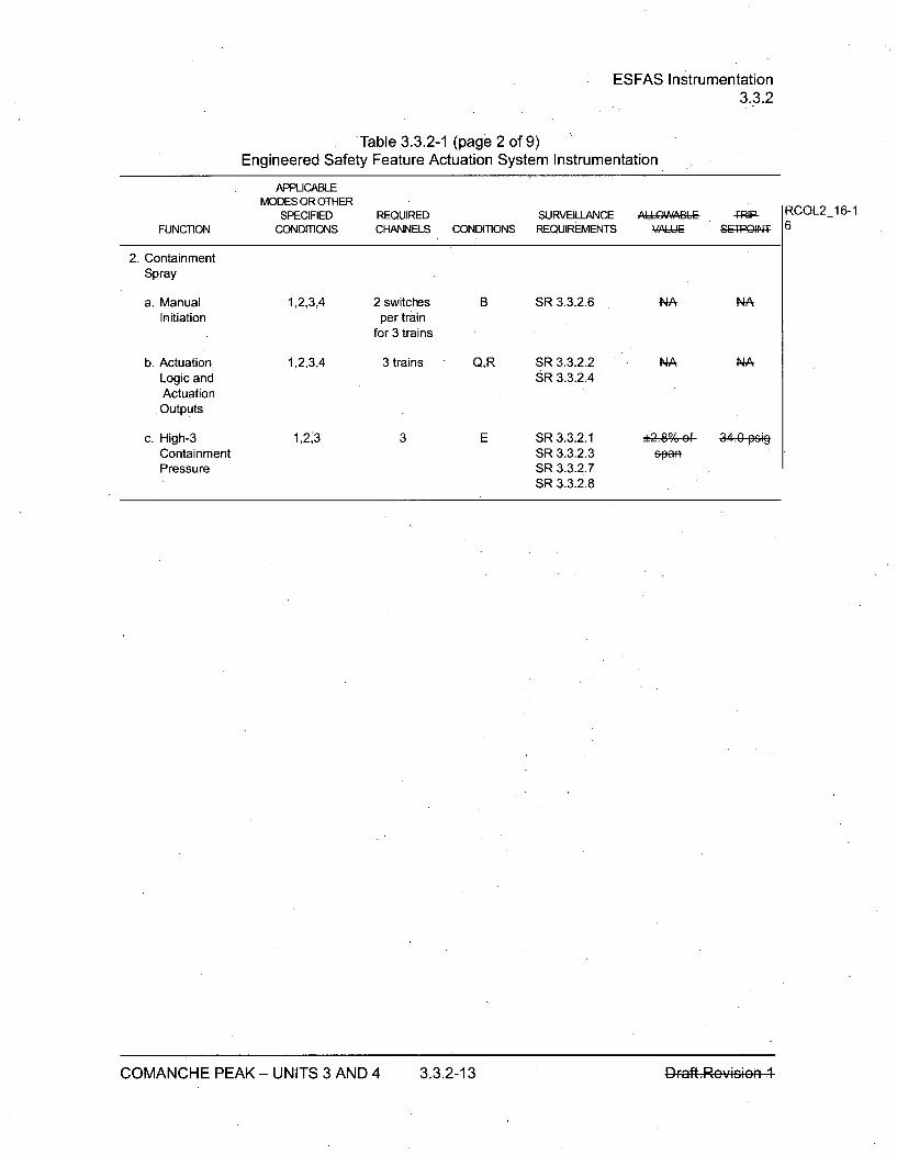
ESFAS Instrumentation3.3.2
Table 3.3.2-1 (page 2 of 9)Engineered Safety Feature Actuation System Instrumentation
APPLICABLEMODES OR OTHER
SPECIFIED REQUIRED SURVEILLANCE AQAbL IRIP-FUNCTION CONDITIONS CHANNELS CONDITIONS REQUIREMENTS VAI4Jq S~Q4:
2. ContainmentSpray
a. Manual 1,2,3,4 2 switches B SR 3.3.2.6 NA NAInitiation per train
for 3 trains
b. Actuation 1,2,3,4 3 trains Q,R SR 3.3.2.2 NA NALogic and SR 3.3.2.4ActuationOutputs
c. High-3 1,23 3 E SR 3.3.2.1 +P,80-ef 3 M peiContainment SR 3.3.2.3 spanPressure SR 3.3.2.7
SR 3.3.2.8
RCOL2_16-16
COMANCHE PEAK - UNITS 3 AND 4 3.3.2-13 1)Fa#,Rev*60
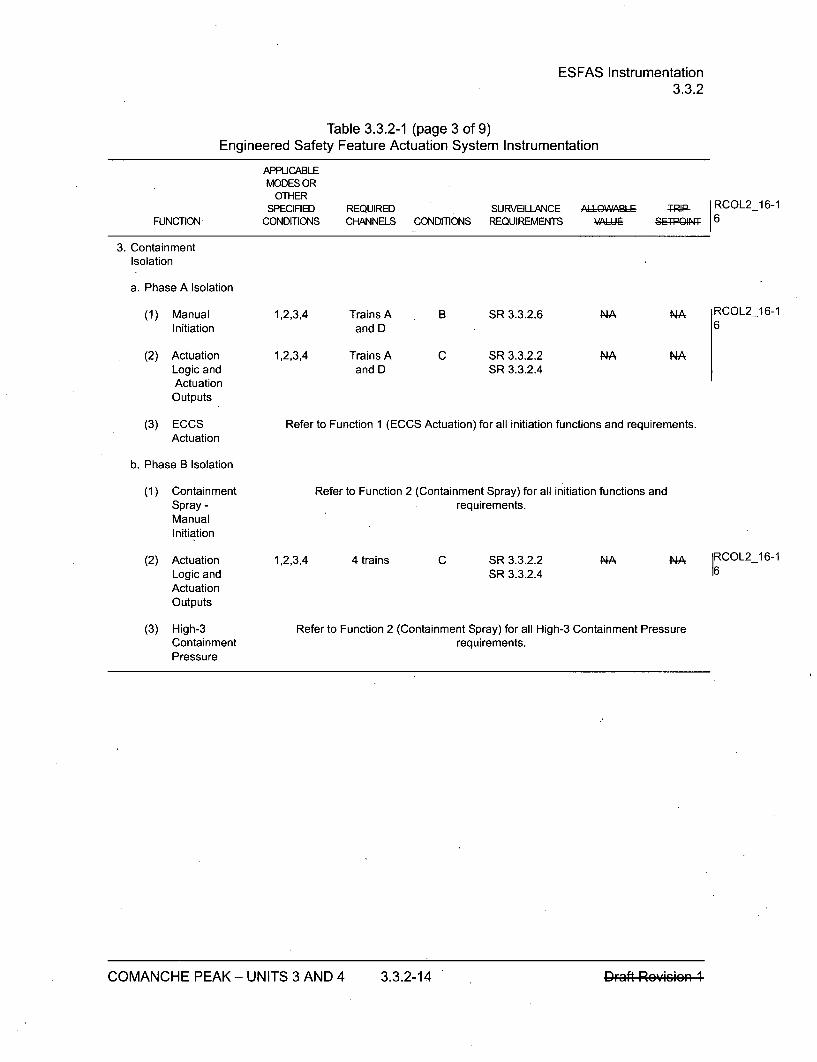
ESFAS Instrumentation3.3.2
Table 3.3.2-1 (page 3 of 9)Engineered Safety Feature Actuation System Instrumentation
APPUCABLEMODES OR
OTHERSPECIFIED
CONDITIONSREQUIREDCHANNELS CONDITIONS
SURVEILLANCEREQUIREMENTS
,-L6OWIILE TRIP RCOL2_16-1SW 11 6FUNCTION
3. Containment
Isolation
a. Phase A Isolation
(1) ManualInitiation
(2) ActuationLogic andActuation
Outputs
(3) ECCSActuation
1,2,3,4
1,2,3,4
Trains Aand D
Trains Aand D
B SR 3.3.2.6
C SR 3.3.2.2SR 3.3.2.4
NA NA RCOL2_16-16
NA NA
Refer to Function 1 (ECCS Actuation) for all initiation functions and requirements.
b. Phase B Isolation
(1) ContainmentSpray -ManualInitiation
(2) ActuationLogic andActuationOutputs
(3) High-3ContainmentPressure
Refer to Function 2 (Containment Spray) for all initiation functions andrequirements.
1,2,3,4 4 trains C SR 3.3.2.2SR 3.3.2.4
NA N-A RCOL2_16-1
Refer to Function 2 (Containment Spray) for all High-3 Containment Pressurerequirements.
COMANCHE PEAK - UNITS 3 AND 4 3.3.2-14

ESFAS Instrumentation3.3.2
Table 3.3.2-1 (page 4 of 9).Engineered Safety Feature Actuation System Instrumentation
APPLICABLEMODES OR
OTHERSPECIFIED REQUIRED SURVEILLANCE ',ALWALE T RCOL2_16-1
FUNCTION CONDITIONS CHANNELS CONDITIONS REQUIREMENTS I -, g 6
4. Main Steam LineIsolation
a. Manual 1,2 (h), 3 (h) Trains A F SR 3.3.2.6 NA NAInitiation and D
b. Actuation Logic 1,2 (h), 3 (h) Trains A S,T SR 3.3.2.2 NA NAand Actuation and D SR 3.3.2.4Outputs
c. High-High 1, 2 (h), 3 (h) 3 D SR 3.3.2.1 _-2.-%ef 22. fp-iContainment SIR 3.3.2.3 spaoPressure SR 3.3.2.7
SIR 3.3.2.8
d. Main SteamLine Pressure
(1) Low Main 1,2 (h),3 (a) 3 per D SR3.3.2.1 _,,%-ef 626M-e-Steam (h) steam SR 3.3.2.3 E-10Line line SR 3.3.2.7Pressure SR 3.3.2.8
(2) High Main 3 (f) (h) 3 per D SR 3.3.2.1 _ 3,•, of%-e0-_ kýSteam steam SR 3.3.2.3 spafLine line SR 3.3.2.7Pressure SR 3.3.2.8NegativeRate
(a) Above the P-1 1 (Pressurizer Pressure) interlock.Mb.~ Time constants usod in the lead!iag ccntr r arc t4 60 soc.nds. and t 5 ....eeend-. RCOL2 16-1
(f) Below the P-1i1 (Pressurizer Pressure) interlock.
Time c.n.tant utilized in the rat/'lag contF9lle, i 6-0 " e..nds. RCOL2_16-1
(h) Except when all MSIVs are closed.
COMANCHE PEAK - UNITS 3 AND 4 3.3.2-15

ESFAS Instrumentation3.3.2
Table 3.3.2-1 (page 5 of 9)Engineered Safety Feature Actuation System Instrumentation
APPUCABLEMODES OR
OTHERSPECIFIED
CONDmONSREQUIREDCHANNELS CONDITIONS
SURVEILLANCEREQUIREMENTS VAI I IP
TRIP RCOL2_16-15; :PQ'lN 6FUNCTION
5. Main FeedwaterIsolation
5A. MainFeedwaterGeR48eIRegulationvalve Closure
I
a. Low Tavg 1,2 (i),3 ('!) 3 •D SR 3.3.2.1SR 3.3.2.3SR 3.3.2.7SR 3.3.2.8
564-F 1RCOL2_16-16
Coincidentwith ReactorTrip, P-4
Refer to Function 11 .a for all P-4 requirements. •
5B. MainFeedwaterIsolation
a. ManualInitiation
b. ActuationLogic andActuationOutputs
c. High-HighSGWater Level
d. ECCSActuation
1,2 (i),3 (i) Trains Aand D
1,2 (i), 3 (i) Trains Aand D
1,2 (i),3ka- (i) 3 per SG
F SR 3.3.2.6
S,T SR 3.3.2.2SR 3.3.2.4
D SR 3.3.2.1SR 3.3.2.3SR 3.3.2.7SR 3.3.2.8
NA NA
NA NA
7-;ef- o%-ef-san spa
RCOL2 16-16
Refer to Function 1 (ECCS Actuation) for all initiation functions andrequirements.
La Above the P-1 1 (Pressurizer Pressure) interlock.(i) Except when all MFIVs, MFRVs, MFBRVs, and SGWFCVs are closed.
(j Except when all MFRVs are closed.
I
COMANCHE PEAK - UNITS 3 AND 4 3.3.2-16 D~r~aft--Re-•sie

ESFAS Instrumentation3.3.2
Table 3.3.2-1 (page 6 of 9)Engineered Safety Feature Actuation System Instrumentation
APPLICABLEMODES OR
OTHERSPECIFIED REQUIRED SURVEILLANCE A..9WABLE RIP
FUNCTION CONDITIONS CHANNELS CONDITIONS REQUIREMENTS V4A,-JI I PQIIN
6. EmergencyFeedwaterActuation
a. Manual Initiation 1,2,3 3 trains F SR 3.3.2.6 NA NA
b. Actuation Logic 1,2,3 3 trains J,T SR 3.3.2.2 NA NAand Actuation SR 3.3.2.4Outputs
c. Low SG Water 1,2,3 3 per SG D SR 3.3.2.1 •3%-ef 4 .3%ofLevel SR 3.3.2.3 sEAf &P&R
SR 3.3.2.7SR 3.3.2.8
d. ECCS Actuation Refer to Function 1 (ECCS Actuation) for all initiation functions and requirements.
e. LOOP Signal 1,2,3 3 per bus F SR 3.3.2.5 A 47-27--for each SR 3.3.2.7 spaf w0th 4 2
EFW SR 3.3.2.8 see-time-train 4eley
f. Trip of all Main 1,2 1 per H SR 3.3.2.6 NA NAFeedwater pump SR 3.3.2.8Pumps
RCOL2_16-16
RCOL2_16-16
COMANCHE PEAK - UNITS 3 AND 4 3.3.2-17DFaft Revisi

ESFAS Instrumentation3.3.2
Table 3.3.2-1 (page 7 of 9)Engineered Safety Feature Actuation System Instrumentation
APPUCABLEMODES OR
OTHERSPECIFIED REQUIRED SURVEILLANCE ,^LLWA, TRIP
FUNCTION CONDITIONS CHANNELS CONDITIONS REQUIREMENTS VAL- I=E 8LPIS
7. EmergencyFeedwaterIsolation
RCOL2_16-16
a. Manual Initiation
b. Actuation Logicand ActuationOutputs
c. High SG WaterLevel
Coincident withReactor Trip, P-4
andAeNo Low MainSteam LinePressure
d. Low Main SteamLine Pressure
8. CVCS Isolation
a. Manual Initiation
b. Actuation Logicand ActuationOutputs
c. High PressurizerWater Level
1,2,3
1,2,3
2 trainsper SG
2 trainsper SG
F SR 3.3.2.6
G SR 3.3.2.2SR 3.3.2.4
D SR 3.3.2.1SR 3.3.2.3SR 3.3.2.7SR 3.3.2.8
NA
NA
NA
NA
1,2,3(a 3 per SG _,39%-ef- o,•-fSPEa S*
Refer to Function 11.a for all P-4 requirements.
Refer to Function 7.d for all initiation functions and requirements.
1,2,3_W 3 per SG
1,2,3
1,2,3
1,2,3_aL
Trains Aand D
Trains Aand D
3
D SSR 3.3.2.1SR 3.3.2.3SR 3.3.2.7SR 3.3.2.8
F SSR 3.3.2.6
G SR 3.3.2.2SR 3.3.2.4
D SR 3.3.2.1SR 3.3.2.3SR 3.3.2.7SR 3.3.2.8
*30,f fspan
626 psig RCOL2_16-16
NA
NA
_ o4.• ef-sG~eA
NA
NA
92%-ef-p•ean
(.a Above the P-i 1 (Pressurizer Pressure) interlock.
COMANCHE PEAK - UNITS 3 AND 4 3.3.2-18

ESFAS Instrumentation3.3.2
Table 3.3.2-1 (page 8 of 9)Engineered Safety Feature Actuation System Instrumentation
APPUCABLEMODES OR
OTHERSPECIFIED REQUIRED SURVEILLANCE AL.' QA4A, L
FUNCTION CONDITIONS CHANNELS CONDITIONS REQUIREMENTS ý44A 1I SEPQIN4
9. Turbine Trip
a. Actuation Logic 1,2,3 4 trains G SR 3.3.2.2 NA NAand Actuation SR 3.3.2.4Outputs
b. Reactor Trip, Refer to Function 11 .a for all P-4 requirements.P-4
c. High-High SG 1,2 (i),3 (i) 3 per SG D SR 3.3.2.1 +3°0; -%-e7- ofWater Level SR 3.3.2.3 spana span{P-44) SR 3.3.2.7
SR 3.3.2.8
10.Reactor CoolantPump Trip
a. ECCS Actuation Refer to Function 1 (ECCS Actuation) for all initiation functions and requirements.
Coincident with Refer to Function 11.a for all P-4 requirements.Reactor Trip,P-4
11 .ESFAS Interlocks
a. Reactor Trip, 1,2,3 3 trains F SR 3.3.2.9 NA N-AP-4
b. Pressurizer 1,2,3 3 I SR 3.3.2.1 :2.6-0,; 44 9p sigPressure, P-11 SR 3.3.2.3 61af
SR 3.3.2.7
(i) Except when all MFIVs, MFRVs, MFBRVs, and SGWFCVs are closed.
RCOL2_16-16
RCOL2_16-16
RCOL2_16-16
COMANCHE PEAK - UNITS 3 AND 4 3.3.2-19 l•r.a.ft--Re•e•+4
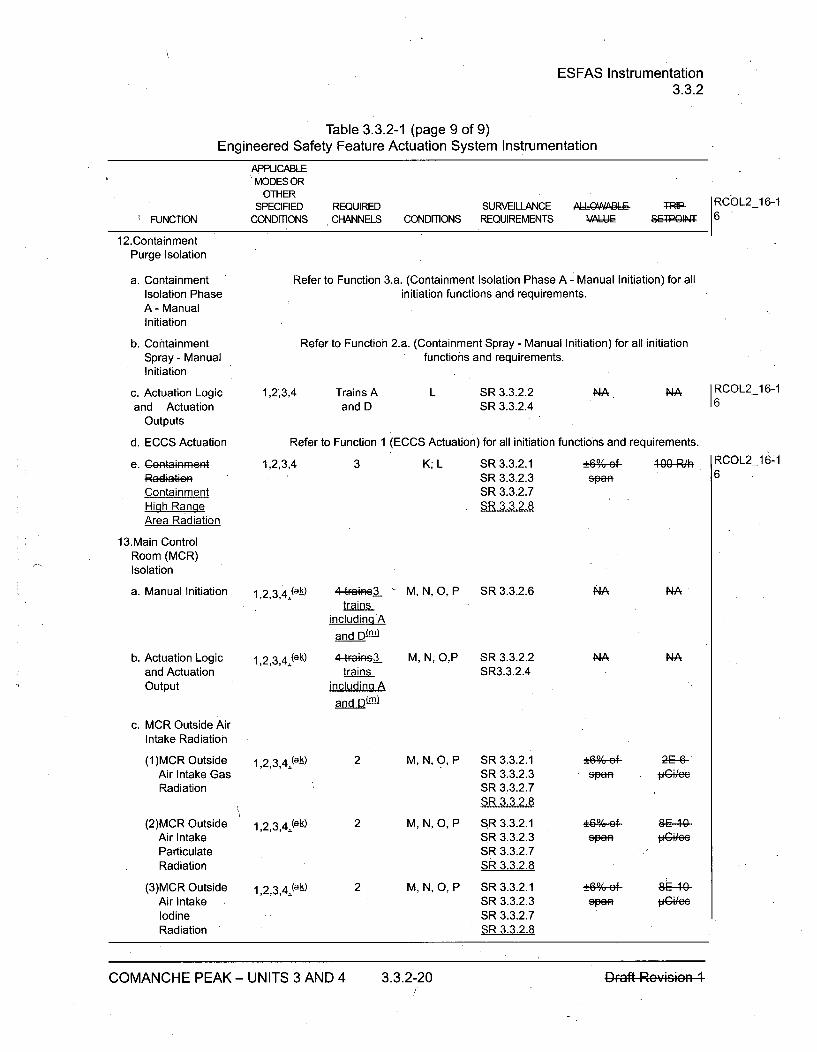
ESFAS Instrumentation3.3.2
Table 3.3.2-1 (page 9 of 9)Engineered Safety Feature Actuation System Instrumentation
APPUCABLE'MODES OR
OTHERSPECIFIED
CONDITIONSREQUIREDCHANNELS CONDITIONS
SURVEILLANCEREQUIREMENTS
A'LOI 9ARILEý A] III;
TRIP RCOL2_16-1SRvQITPC 6*FUNCTION
112.ContainmentPurge Isolation
a. ContainmentIsolation PhaseA- ManualInitiation
b. ContainmentSpray - ManualInitiation
c. Actuation Logicand Actuation
Outputs
d. ECCS Actuation
e. Gentainment
ContainmentHigh RangeArea Radiation
13.Main ControlRoom (MCR)Isolation
a. Manual Initiation
b. Actuation Logicand ActuationOutput
c. MCR Outside AirIntake Radiation
Refer to Function 3.a. (Containment Isolation Phase A - Manual Initiation) for allinitiation functions and requirements.
Refer to Function 2.a. (Containment Spray - Manual Initiation) for all initiationfunctions and requirements.
1,2,3,4 Trains Aand D
L SR 3.3.2.2SR 3.3.2.4
NA. NA RCOL2_16-116
Refer to Function 1 (ECCS Actuation) for all initiation functions and requirements.
1,2,3,4 3 K; L SR 3.3.2.1SR 3.3.2.3SR 3.3.2.7SR 3.3.2.8
.±60,; pfspan
1.g0 R'h RCOL2_16-16
11,2,3,4=(a-k) 4.48FeIG-3_trains
including A
and D ra
1,2,3,4(a-) 4t-Fais3trains
including A
and D~ml
M, N, 0, P SR 3.3.2.6
M, N, O,P SR 3.3.2.2SR3.3.2.4
NA
4A
NA
NA
(1)MCR OutsideAir Intake GasRadiation
(2)MCR OutsideAir IntakeParticulateRadiation
(3)MCR OutsideAir IntakeIodineRadiation
11,2,3,4(a-k)
11,2,3,4j(-)
11,2,3,4•(a-)
2 M, N, O, P SR 3.3.2.1SR 3.3.2.3SR 3.3.2.7SR 3.3.2.8
2 M, N, 0, P SIR 3.3.2.1SR 3.3.2.3SR 3.3.2.7SR 3.3.2.8
2 M, N, O, P SR 3.3.2.1SR 3.3.2.3SR 3.3.2.7SR 3.3.2.8
span2E-6
pCi,'e
span VGi~ee
COMANCHE PEAK - UNITS 3 AND 4 3.3.2-20 OFaft Rey*rm
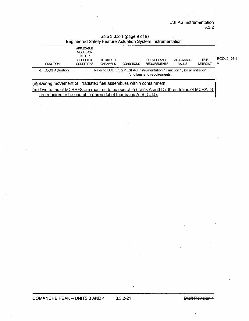
ESFAS Instrumentation3.3.2
Table 3.3.2-1 (page 9 of 9)Engineered Safety Feature Actuation System Instrumentation
APPUCABLEMODES OR
OTHERSPECIFIED REQUIRED SURVEILLANCE ALLIV
CONDmONS CHANNELS CONDITIONS REQUIREMENTS VAL=.N.ABL TRIP RCOL2_16-1
W4 &E-TpQ 6FUNCTION
d. ECCS Actuation Refer to LCO 3.3.2,. "ESFAS Instrumentation," Function 1, for all initiationfunctions and requirements.
(ak)During movement of irradiated fuel assemblies within containment.
(mnTwo trains of MCREFS are required to be operable (trains A and D): three trains of MCRATSare required to be operable (three out of four trains A, B, C. D).
COMANCHE PEAK - UNITS 3 AND 4 3.3.2-21 DFaft Reymsa
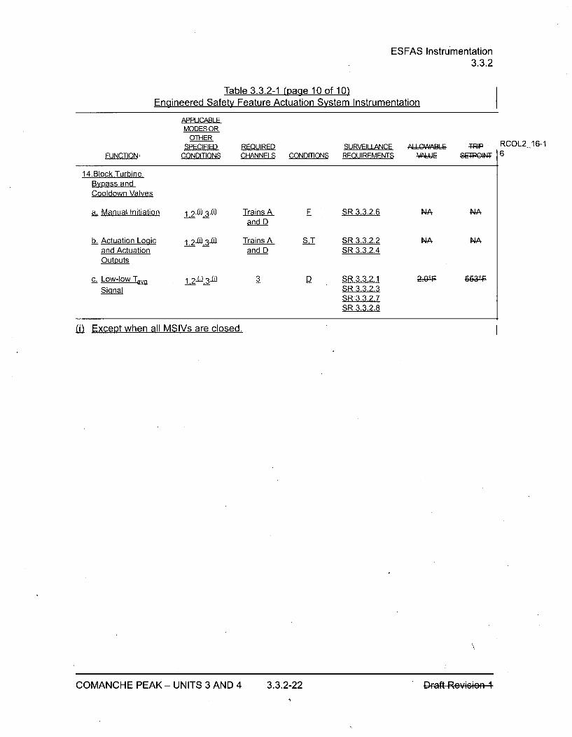
ESFAS Instrumentation3.3.2
Table 3.3.2-1 (page 10 of 10)IPnr inaarrlH .qfntl Feature Actuation System Instrumentation
-- " ~ ~ ~ F at r A c ua io .. . . . . .. S.. . . .. . .. . .s t .. .. .. ... .. ..... . In a
APPLICABLEMODES OR
OTHER
SPECIFIEDCONDITIONS
REQUIREDCHANNELS
SURVEILLANCECONDmONS REQUIREMENTS
AIIWAAIEu TRP RCOL2_16-1g 6FUNCTION)
14.Block TurbineBypass andCooldown Valves
a. Manual Initiation
b. Actuation Logicand ActuationOutputs
1 2 .0 3 -0 Trains Aand D
1 2-W-3-01 Trains Aand D
F SR 3.3.2.6
S.T SR 3.3.2.2SR 3.3.2.4
D SR 3.3.2.1SR 3.3.2.3SR 3.3.2.7SR 3.3.2.8
NA
NA
NA
NA
c. Low-low T1vaSignal
-12-U.3-U 3 2.02F 6631p
(i Except when all MSIVs are closed. I
COMANCHE PEAK - UNITS 3 AND 4 3.3.2-22 DFaft Rey*sw

LOP Class 1 E GTG Start Instrumentation3.3.5
SURVEILLANCE REQUIREMENTS
SURVEILLANCE FRE QUENCY
SR 3.3.5.1 Perform CHANNEL CHECK. In accordancewith theSurveillanceFrequency ControlProgram
SR 3.3.5.2 Perform TADOT for LOP undervoltage relays. In accordancewith theSurveillanceFrequency ControlProgram
S R 3.3.5.3 Perform CHANNEL CALIBRATION for LOP In accordanceundervoltage relays with N.minal Trip Sctpoint with theand Allowabic Valuc as followcin accordance with Surveillancethe SCP with following time delay: Frequency Control
Programa. Loss of voltage Allowabe I Valuce> 4830 V
with a time delay of _< 2 second
Loss of voltage Nominal TrFip Setpoint4727 V with a tome delay of 2 sccond.
b. Degraded voltage All^wable Va6uc--6244-V-with a time delay of <10 seconds.
Deg"adcd \;ltag- Nominal Trip Sctpein,•6314 V with a tome delay ef 10 scconds-..
NOTE: In all eass, the Yalucs spesificdI for Sctpoints will be confimed following eemplctOn of thAplant spccifie sctpeint study. These values will be ealculated in aesordanco with the setpitmcthedelegy aftcr sclectiOR of plant spccific ntuettos
RCOL2_16-16
COMANCHE PEAK - UNITS 3 AND 4 3.3.5-2 DFaft Rey*soen 1

DAS Instrumentation3.3.6
Table 3.3.6-1 (page 1 of 2)Diverse Actuation System Instrumentation
APPLICABLEMODES OR
OTHER NMIALSPECIFIED REQUIRED SURVEILLANCE A'LQW, A -LE
FUNCTION CONDITIONS CHANNELS CONDITIONS REQUIREMENTS V 1
1. Reactor Trip/ Turbine Trip/ MFW Isolation
a. Manual Initiation 1 ,2, 3 (a) 1 (b) A SIR 3.3.6.5 NA NASIR 3.3.6.6
b. Automatic 1,2, 3 (a) 2 A SIR 3.3.6.4 NA NAActuation Logic SR 3.3.6.5and ActuationOutputs
c. Low Pressurizer 1 ,2, 3 (a) 2 A SR 3.3.6.1 -21.6% e- 182-psigPressure SR 3.3.6.2 sfaq
SR 3.3.6.3
d. High Pressurizer 1 ,2, 3 (a) 2 A SR 3.3.6.1 h2.6-0e 242&psigPressure SR 3.3.6.2 sfa
SR 3.3.6.3
e. Low Steam 1 ,2 ,3 (a) 1 per SG A SR 3.3.6.1 _.30%e O 79;o, ,,spaGenerator for any 2 SR 3.3.6.2 GfaAWater Level SGs SR 3.3.6.3
f. Rod Drive 1,2, 3 (a) 2(1 for A SR 3.3.6.6 NA NAMotor-Genera- eachtor seeSet MG-set
Set)
2. EFWS Actuation
a. Manual Initiation 1 ,2,3 (a) 1 (b) A SR 3.3.6.5 NA NA
b. Automatic 1,2,3(a) 2 A SR 3.3.6.5 NA NAActuation Logicand ActuationOutputs
c. Low Steam Refer to Function i.e for all Low Steam Generator Water Level requirements.GeneratorWater Level
(a) With the Pressurizer Pressure > P-1i1(b) Manual initiation functions require operation of 2 switches, the Permissive Switch for DAS HSI
and the manual initiation switch on the DHP.
NOTE: In all case, the valucs speeificd fGc All^wablc Values and SctpeiAt• will be eonfir.medfellowing completion of thc plant specific setpcint study. These values will be calculated inaecardanec with the setpeint mcthedolegy aftcr seleeteian cf plant speeificietu natn.
RCOL2_16-16
RCOL2_16-16
COMANCHE PEAK - UNITS 3 AND 4 3.3.6-4 DFaft Reyisw
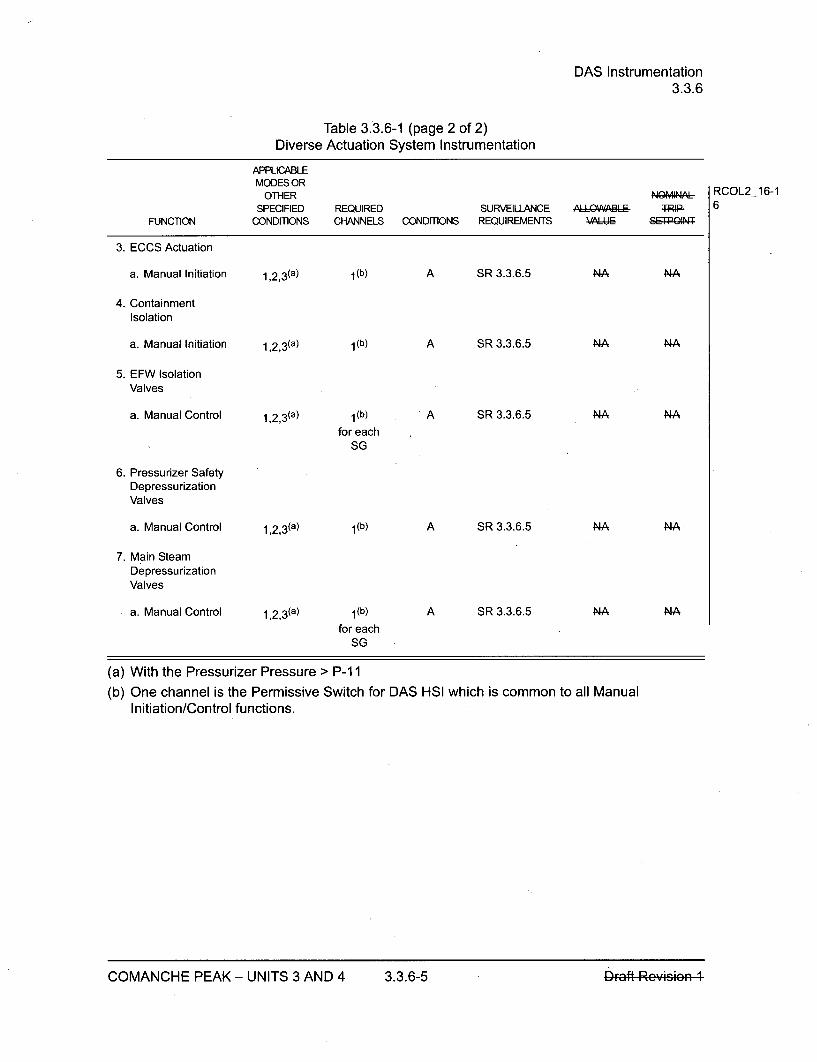
DAS Instrumentation3.3.6
Table 3.3.6-1 (page 2 of 2)Diverse Actuation System Instrumentation
APPLICABLEMODES OR
OTHER NOMINAISPECIFIED REQUIRED SURVEILLANCE ,A'IL 94AI-, TRIP-
FUNCTION CONDmONS CHANNELS CONDmONS REQUIREMENTS VAI'I RPQON
3. ECCS Actuation
a. Manual Initiation 1 ,2, 3 (a) 1(b) A SR 3.3.6.5 NA NA
4. ContainmentIsolation
a. Manual Initiation 1 ,2,3(a) 1(b) A SR 3.3.6.5 NA NA
5. EFW IsolationValves
a. Manual Control 1,2,3(a) 1(b) A SR 3.3.6.5 NA NA
for eachSG
6. Pressurizer SafetyDepressurizationValves
a. Manual Control 1,2,3(a) 1 (b) A SR 3.3.6.5 NA NA
7. Main SteamDepressurizationValves
a. Manual Control 1 ,2,3 (a) 1 (b) A SR 3.3.6.5 NA NA
-for eachSG
(a) With the Pressurizer Pressure > P-11(b) One channel is the Permissive Switch for DAS HSI which is common to all Manual
Initiation/Control functions.
RCOL2_16-16
COMANCHE PEAK - UNITS 3 AND 4 3.3.6-5 _hraft Rey*soen 1
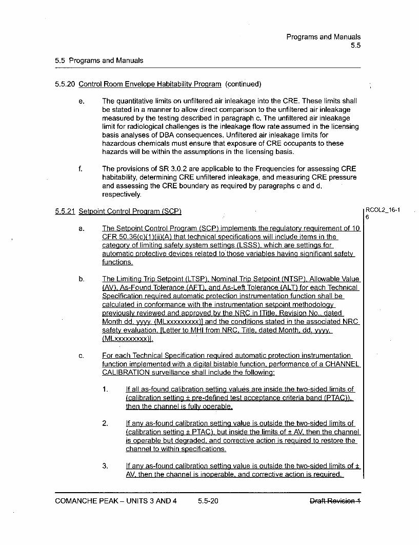
Programs and Manuals5.5
5.5 Programs and Manuals
5.5.20 Control Room Envelope Habitability Program (continued)
e. The quantitative limits on unfiltered air inleakage into the CRE. These limits shallbe stated in a manner to allow direct comparison to the unfiltered air inleakagemeasured by the testing described in paragraph c. The unfiltered air inleakagelimit for radiological challenges is the inleakage flow rate assumed in the licensingbasis analyses of DBA consequences. Unfiltered air inleakage limits forhazardous chemicals must ensure that exposure of CRE occupants to thesehazards will be within the assumptions in the licensing basis.
f. The provisions of SR 3.0.2 are applicable to the Frequencies for assessing CREhabitability, determining CRE unfiltered inleakage, and measuring CRE pressureand assessing the CRE boundary as required by paragraphs c and d,respectively.
5.5.21 Setpoint Control Program (SCP) RCOL2_16-1
6
a. The Setpoint Control Program (SCP) implements the regulatory requirement of 10CFR 50.36(c)(1 )(ii)(A) that technical specifications will include items in thecategory of limiting safety system settings (LSSS), which are settings forautomatic protective devices related to those variables having significant safetyfunctions.
b. The Limiting Trip Setpoint (LTSP), Nominal Trip Setpoint (NTSP), Allowable Value(AV). As-Found Tolerance (AFT). and As-Left Tolerance (ALT) for each TechnicalSpecification required automatic protection instrumentation function shall becalculated in conformance with the instrumentation setpoint methodologypreviously reviewed and approved by the NRC in [Title. Revision No., datedMonth dd, yyyy, (MLxxxxxxxxx)] and the conditions stated in the associated NRCsafety evaluation, [Letter to MHI from NRC, Title, dated Month, dd. yyyy.(MLxxxxxxxxx)].
c. For each Technical Specification required automatic protection instrumentationfunction implemented with a digital bistable function, performance of a CHANNELCALIBRATION surveillance shall include the following:
1. If all as-found calibration setting values are inside the two-sided limits of(calibration setting ± pre-defined test acceptance criteria band (PTAC)),then the channel is fully operable.
2. If any as-found calibration setting value is outside the two-sided limits of(calibration setting ± PTAC), but inside the limits of ± AV, then the channelis operable but degraded, and corrective action is required to restore thechannel to within specifications.
3. If any as-found calibration setting value is outside the two-sided limits of ±AV, then the channel is inoperable, and corrective action is required,
COMANCHE PEAK - UNITS 3 AND 4 5.5-20 DFaft ReY669
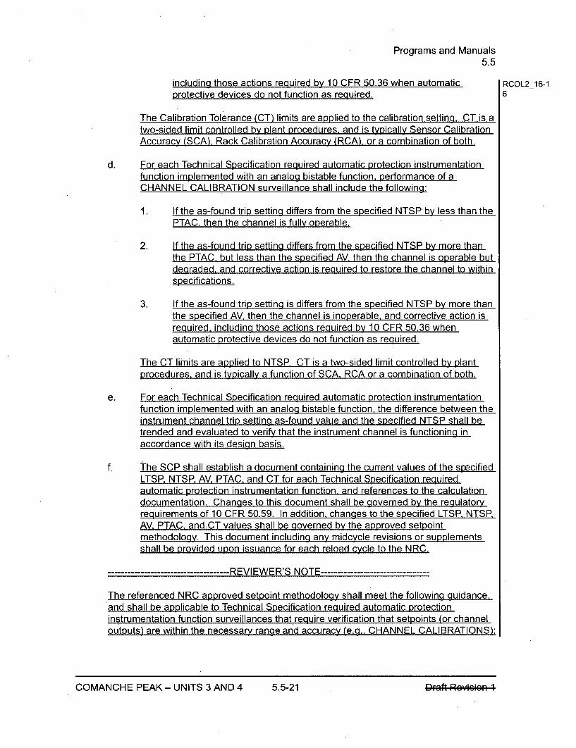
Programs and Manuals5.5
including those actions required by 10 CFR 50.36 when automatic RCOL2_16-1protective devices do not function as required. 6
The Calibration Tolerance (CT) limits are applied to the calibration setting. CT is atwo-sided limit controlled by plant procedures, and is typically Sensor CalibrationAccuracy (SCA), Rack Calibration Accuracy (RCA). or a combination of both.
d. For each Technical Specification required automatic protection instrumentationfunction implemented with an analog bistable function, performance of aCHANNEL CALIBRATION surveillance shall include the following:
1. If the as-found trip setting differs from the specified NTSP by less than thePTAC, then the channel is fully operable.
2. If the as-found trip setting differs from the specified NTSP by more thanthe PTAC, but less than the specified AV, then the channel is operable butdegraded, and corrective action is required to restore the channel to withinspecifications.
3. If the as-found trip setting is differs from the specified NTSP by more thanthe specified AV, then the channel is inoperable, and corrective action isrequired, including those actions required by 10 CFR 50.36 when.automatic protective devices do not function as required.
The CT limits are applied to NTSP. CT is a two-sided limit controlled by plantprocedures, and is typically a function of SCA, RCA or a combination of both.
e. For each Technical Specification required automatic protection instrumentationfunction implemented with an analog bistable function, the difference between theinstrument channel trip setting as-found value and the specified NTSP shall betrended and evaluated to verify that the instrument channel is functioning inaccordance with its design basis.
f. the SCP shall establish a document containing the current values of the specifiedLTSP, NTSP. AV, PTAC, and CT for each Technical Specification requiredautomatic protection instrumentation function, and references to the calculationdocumentation. Changes to this document shall be governed by the regulatoryrequirements of 10 CFR 50.59. In addition, changes to the specified LTSP. NTSRAV, PTAC. and.CT values shall be governed by the approved setpointmethodology. This document including any midcycle revisions or supplementsshall be provided upon issuance for each reload cycle to the NRC.
----- -------------- REVIEWER'S NOTE -----------------
The referenced NRC approved setpoint methodology shall meet the following guidance,and shall be applicable to Technical Specification required automatic protectioninstrumentation function surveillances that require verification that setpoints (or channeloutputs) are within the necessary range and accuracy (e.g., CHANNEL CALIBRATIONS):
COMANCHE PEAK - UNITS 3 AND 4 5.5-21
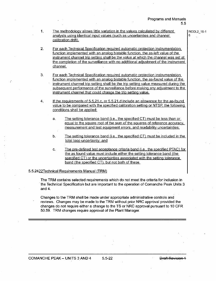
Programs and Manuals5.5
1. The methodology allows little variation in the values calculated by different RCOL2_16-1analysts using identical input values (such as uncertainties and channel 6calibration drift).
2. For each Technical Specification required automatic protection instrumentationfunction implemented with an analog bistable function, the as-left value of theinstrument channel trip setting shall be the value at which the channel was set atthe completion of the surveillance with no additional adiustment of the instrumentchannel.
3. For each Technical Specification required automatic protection instrumentationfunction implemented with an analog bistable function, the as-found value of theinstrument channel trip setting shall be the trip setting value measured during thesubsequentperformance of the surveillance before making any adjustment to theinstrument channel that could change the trip setting value.
4. If the requirements of 5.5.21 .c. or 5.5.21 .d include an allowance for the as-foundvalue to be compared with the specified calibration setting or NTSP, the followingconditions shall be applied:
a. The setting tolerance band (i.e., the specified CT) must be less than orequal to the square root of the sum of the squares of reference accuracy,measurement and test equipment errors, and readability uncertainties:
b. The setting tolerance band (i.e., the specified CT) must be included in thetotal loop uncertainty: and
c. The pre-defined test acceptance criteria band (i.e.. the specified PTAC) forthe as found value must include either the setting tolerance band (thespecified CT) or the uncertainties associated with the setting toleranceband (the specified CT), but not both of these.
5.5.2422Technical Requirements Manual (TRM)
The TRM contains selected requirements which do not meet the criteria for inclusion inthe Technical Specification but are important to the operation of Comanche Peak Units 3and 4.
Changes to the TRM shall be made under appropriate administrative controls andreviews. Changes may be made to the TRM without prior NRC approval provided thechanges do not require either a change to the TS or NRC approval pursuant to 10 CFR50.59. TRM changes require approval of the Plant Manager.
COMANCHE PEAK - UNITS 3 AND 4 5.5-22 IDFaft Reyms'
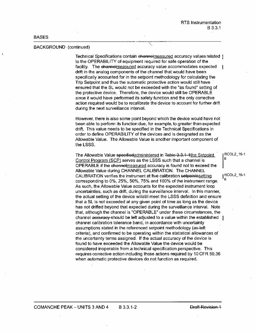
RTS InstrumentationB 3.3.1
BASES
BACKGROUND (continued)
Technical Specifications contain ehnaelrmeasured accuracy values relatedto the OPERABILITY of equipment required for safe operation of thefacility. The eha.e. measured accuracy value accommodates expecteddrift in the analog components of the channel that would have beenspecifically accounted for in the setpoint methodology for calculating theTrip Setpoint and thus the automatic protective action would still haveensured that the SL would not be exceeded with the "as found" setting ofthe protective device. Therefore, the device would still be OPERABLEsince it would have performed its safety function and the only correctiveaction required would be to recalibrate the device to account for further driftduring the next surveillance interval.
However, there is also some point beyond which the device would have notbeen able to perform its function due, for example, to greater than expecteddrift. This value needs to be specified in the Technical Specifications inorder to define OPERABILITY of the devices and is designated as theAllowable Value. The Allowable Value is another important component ofthe LSSS.
The Allowable Value speeifiedadministered in Table 3.3.1 !the Setpoint RCOL2_16-1
Control Program (SCP) serves as the LSSS such that a channel is 6
OPERABLE if the ehaneimeasured accuracy is found not to exceed theAllowable Value during CHANNEL CALIBRATION. The CHANNELCALIBRATION verifies the instrument at five calibration setpein4setting RCL26-1
corresponding to 0%, 25%, 50%, 75% and 100% of the instrument range. 6
As such, the Allowable Value accounts for the expected instrument loopuncertainties, such as drift, during the surveillance interval. In this manner,the actual setting of the device willstill meet the LSSS definition and ensurethat a SL is not exceeded at any given point of time as long as the devicehas not drifted beyond that expected during the surveillance interval. Notethat, although the channel is "OPERABLE" under these circumstances, thechannel ae6eauy should be left adjusted to a value within the establishedchannel calibration tolerance band, in accordance with uncertaintyassumptions stated in the referenced setpoint methodology (as-leftcriteria), and confirmed to be operating within the statistical allowances ofthe uncertainty terms assigned. If the actual accuracy of the device isfound to have exceeded the Allowable Value the device would beconsidered inoperable from a technical specification perspective. Thisrequires corrective action including those actions required by 10 CFR 50.36when automatic protective devices do not function as required.
COMANCHE PEAK - UNITS 3 AND 4 B 3.3.1-2

RTS InstrumentationB 3.3.1
BASES
BACKGROUND (continued)
Generally, if a parameter is used for input to the protection circuits and acontrol function, three channels with a two-out-of-three logic are alsosufficient to provide the required reliability and redundancy. The SignalSelection Algorithm (SSA) within the PCMS ensures the control systemscan withstand an input failure to the control system without causingerroneous control system operation which would otherwise require theprotection function actuation. Since the input failure does not cause anerroneous control system action thatchallenges the protection function, theinput failure is considered a single failure in the RTS and the RTS remainscapable of providing its protective function with the remaining two operablechannels. Again, a single failure will neither cause nor prevent theprotection function actuation. These requirements are described inIEEE-603-1991 (Ref. 4). The actual number of channels required for eachunit parameter is specified in Reference 2.
The RTB trains are arranged in a two out of four configuration. Therefore,three logic trains are required to ensure no single random failure of a logictrain will disable the RTS. The logic trains are designed such that testingrequired while the reactor is at power may be accomplished withoutcausing trip. Provisions allow removing logic trains from service duringmaintenance.
Allowable Values and RTS Setpoints
The Trip Setpoints used in the digital bistables are based on the AnalyticalLimits defined in the accident analysis and the channel uncertainty. Theselection of these Trip Setpoints is such that adequate protection isprovided when all sensor and processing time delays are taken intoaccount. To allow for calibration tolerances, instrumentation uncertainties,instrument drift, and severe environment errors for those RTS channels thatmust function in harsh environments as defined by 10 CFR 50.49 (Ref. 5),the Trip Setpoints .pee.fiedadministered in Table3....1..the SCP in theaccompanying LCO are conservative with respect to the Analytical Limits.The methodology used to calculate the Allowable Values and Trip Setpointsincorporates all of the known uncertainties applicable to each channel (Ref.2). The magnitudes of these uncertainties are factored into thedetermination of each Trip Setpoint and corresponding Allowable Value.The Trip Setpoint entered into the 4i4itaF-bistable is more conservative thanthat specified by the Analytical Limit (LSSS) to account for measurementerrors detectable by the CHANNEL CALIBRATION. The Allowable Valueserves as the Technical Specification OPERABILITY limit fbr the purpose ofthe CHANNEL CALIBRATION. One example of such a change inmeasurement error is drift during the surveillance interval. If the measuredaccuracy does not exceed the Allowable Value, the channel is consideredOPERABLE.
I
RCOL2_16-16
I RCOL2_16-16
COMANCHE PEAK - UNITS 3 AND 4 B 3.3.1-5 DFaft Reyesmen 1
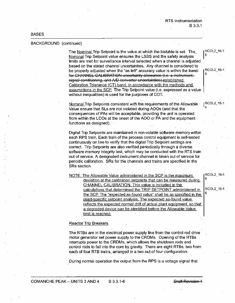
RTS InstrumentationB 3.3.1
BASES
BACKGROUND (continued)
The Nominal Trip Setpoint is the value at which the bistable is set. The-Nominal Trip Setpoint value ensures the LSSS and the safety analysislimits are met for surveillance interval selected when a channel is adjustedbased on the stated channel uncertainties. Any channel is considered tobe properly adjusted when the "as left" accuracy value is within the baRd-fo•r HANNEL CALIBRATION uneertainty allewancz (i.e. !k n.struient,signal . .nditi.ning, and A.ID convete. unee rtaintis)satablishedCalibration Tolerance (CT) band, in accordance with the methods andassumptions. in the SCP. The Trip Setpoint value (i.e. expressed as a valuewithout inequalities) is used for the purposes of COT.
Nominal Trip Setpoints consistent with the requirements of the AllowableValue ensure that SLs are not violated during AOOs (and that theconsequences of PAs will be acceptable, providing the unit is operatedfrom within the LCOs at the onset of the AOO or PA and the equipmentfunctions as designed).
Digital Trip Setpoints are maintained in non-volatile software memory withineach RPS train. Each train of the process control equipment is self-testedcontinuously on line to verify that the digital Trip Setpoint settings arecorrect. Trip Setpoints are also verified periodically through a diversesoftware memory integrity test, which may be conducted with the RTS trainout of service. A designated instrument channel is taken out of service forperiodic calibration. SRs for the channels and trains are specified in theSRs section.
NOTE: The Allowable Value administered in the SCP is the maximumdeviation at the calibration setpoints that can be measured duringCHANNEL CALIBRATION. This value is included in thecalculations that determined the TRIP SETPOINT administered inthe SCR The "expected as-found value" shall be as specified in theplant-specific setpoint analysis. The expected as-found valuereflects the expected normal drift of actual plant equipment. so thata degraded device can be identified before the Allowable Valuelimit is reached.
Reactor Trip Breakers
The RTBs are in the electrical power supply line from the control rod drivemotor generator set power supply to the CRDMs. Opening of the RTBsinterrupts power to the CRDMs, which allows the shutdown rods andcontrol rods to fall into the core by gravity. There are eight RTBs, two fromeach of four RTB trains, arranged in a two out of four configuration.
During normal operation the output from the RPS is a voltage signal that
RCOL2_16-16
RCOL2_16-16
RCOL2 16-16
RCOL2_16-16
RCOL2_16-16
COMANCHE PEAK - UNITS 3 AND 4 B 3.3.1-6 DFaft Rey*rm

RTS InstrumentationB 3.3.1
BASES
BACKGROUND (continued)
energizes the undervoltage coils in the RTBs. When protective action isrequired, the RPS output voltage signal is removed, the undervoltage coilsare de-energized, the breaker trip lever is actuated by the de-energizedundervoltage coil, and the RTBs are tripped open. This allows theshutdown rods and control rods to fall into the core. In addition to thede-energization of the undervoltage coils, each breaker is also equippedwith a shunt trip device that is energized to trip the breaker open uponreceipt of a reactor trip signal from the RPS. Eiftler the undervoltage coil orthe shunt trip mechanism is sufficient by itself, thus providing a diverse tripmechanism.
The decision logic matrix Functions are described in the functionaldiagrams included in Reference 2. In addition to the reactor trip or ESF,these diagrams also describe the various "permissive interlocks" that areassociated with unit conditions. Each train has built in self-testing thatautomatically tests the decision logic Functions while the unit is at power.When any one or two trains are taken out of service for testing, the othertwo trains are capable of providing unit monitoring and protection until thetesting has been completed.
APPLICABLE The RTS functions to maintain the SLs during all AQOs and mitigates theSAFETY consequences of PAs in all MODES in which the Rod Control System isANALYSES, LCO, capable of rod withdrawal or one or more rods are not fully inserted.andAPPLICABILITY Each of the analyzed accidents and transients can be detected by one or
more RTS Functions. The accident analysis described in Reference 3 and9 takes credit for most RTS trip Functions. RTS trip Functions notspecifically credited in the accident analysis are qualitatively credited in thesafety analysis and the NRC staff approved licensing basis for the unit.These RTS trip Functions may provide protection for conditions that do notrequire dynamic transient analysis to demonstrate Function performance.They may also serve as backups to RTS trip Functions that were creditedin the accident analysis.
The LCO requires all instrumentation performing an RTS Function, listed inTable 3.3.1-1 in the accompanying LCO, to be OPERABLE. A channel isOPERABLE provided the "as-found" aeeecy value, measured duringsurveillance testing, does not exceed its associated Allowable Value. Fordigital functions Allowable Values are defined in terms pertinent to thechannel calibration setpoints. For analog functions Allowable Values aredefined in terms pertinent to the Nominal Trip Setpoint. A Nominal TripSetpoint may be set more conservative than the NomRinlfLimiting TripSetpoint as necessary in response to plant conditions. Failure of anyinstrument renders the affected channel(s) inoperable and reduces thereliability of the affected Functions.
RCOL2_16-16
COMANCHE PEAK - UNITS 3 AND 4 B 3.3.1-7 DFa# Reyds*

RTS InstrumentationB 3.3.1
BASES
APPLICABLE SAFETY ANALYSES, LCO, and APPLICABILITY (continued)
The LCO generally requires OPERABILITY of three or two channels ineach instrumentation Function, three trains of Manual Reactor Trip in eachlogic Function, and three trains in each Automatic Trip Logic Function.Three OPERABLE instrumentation channels in a two-out-of-threeconfiguration are required when one RTS channel is also used as a controlsystem input. The SSA within the control system prevents the possibility ofthe shared channel failing in such a manner that it creates a transient thatrequires RTS action. The input failure is considered a single failure in theRTS and RTS remains capable of providing its protective function with theremaining two operable channels.in this ease, the RTS well still p...id.pratection, crc n With random failue ro f ene of the othcr tW8 pratcctienehannels. The SSA ensures there is no potential for control system andprotection system interaction that could simultaneously create a need forRTS trip and disable one RTS channel. The two-out-of-three configurationallows one channel to be tripped during maintenance or testing withoutcausing a reactor trip. Specific exceptions to the above general philosophyexist and are discussed below.
In all cases where the LCO states "Restore channel or train to OPERABLEstatus", this means restore the required number of channels or trains toOPERABLE status. Therefore, restoration of an alternate channel or train,other than the failed channel or train, is also acceptable.
In Table 3.3.1 1, the valucc spccificd for Allowablc Values and Sctpaintswill be confirmced following eemplction of the plant spccifie setpeffit study.These Yalu cc willbe ca culatcd in aeeerdanee with the stpeintmcthodelegy aftcr sclcctien ef plant spccfifie inctRumcntatienc.
Reactor Trip System Functions
The safety analyses and OPERABILITY requirements applicable to eachRTS Function are discussed below:
1. Manual Reactor Trip initiation
The Manual Reactor Trip initiation ensures that the control roomoperator can initiate a reactor trip at any time by using any two outof four hardwired reactor trip switches in the control room. AManual Reactor Trip initiation accomplishes the same results asany one of the automatic trip Functions. It is used by the reactoroperator to shut down the reactor whenever any parameter israpidly trending toward its Trip Setpoint.
RCOL2_16-16
COMANCHE PEAK - UNITS 3 AND 4 B 3.3.1-8 IDFaft Reyws*

RTS InstrumentationB 3.3.1
BASES
ACTIONS (continued)
reduction action completion times.
The Required Actions are modified by a Note that allows placing onechannel in bypass for up to 12 hours while performing routine surveillancetesting. These times are justified because this is an anticipatory trip that isnote credited in the safety analysis, and a diverse turbine trip also initiatedfrom the Turbine Emergency Oil Pressure.
SURVEILLANCE The SRs for each RTS Function are identified by the SRs column ofREQUIREMENTS Table 3.3.1-1 for that Function.
A Note has been added to the SR Table stating that Table 3.3.1-1determines which SRs apply to which RTS Functions.
Note that each channel of process protection supplies all trains of the RTS.However, when testing a Channel, it is only necessary to manually verifythat the channel is OPERABLE in its respective train. This is because theinterface to other trains is continuously verified through self-testing.Self-testing is confirmed through periodic COT and ACTUATION LOGICTEST. The CHANNEL CALIBRATION is performed in a manner that isconsistent with the acsumptiens used in analytically calculating the-rcquircd chacrnnl accuracicSection 5.5.21, SCP.
SR 3.3.1.1
Performance of the CHANNEL CHECK ensures that gross failure ofinstrumentation has not occurred. A CHANNEL CHECK is normally acomparison of the parameter indicated on one channel to a similarparameter on other channels. It is based on the assumption thatinstrument channels monitoring the same parameter should readapproximately the same value. Significant deviations between the twoinstrument channels could be an indication of excessive instrument drift inone of the channels or of something even more serious. A CHANNELCHECK will detect gross channel failure; thus, it is key to verifying that theinstrumentation continues to operate properly between each CHANNELCALIBRATION.
Agreement criteria are determined based on a combination of the channelinstrument uncertainties. If a channel is outside the criteria, it may be anindication that the sensor or the signal processing equipment has driftedoutside its limit.
The Surveillance Frequency is based on operating experience, equipmentreliability, and plant risk and is controlled under the Surveillance FrequencyControl Program.
RCOL2_16-1
16
COMANCHE PEAK - UNITS 3 AND 4 B 3.3.141 Draft Rcvizion 1COMANCHE PEAK - UNITS 3 AND 4 B 3.3.1-41 DI ftRrey• ,-s-*

RTS InstrumentationB 3.3.1
BASES
SURVEILLANCE REQUIREMENTS (continued)
CHANNEL CALIBRATIONS must be performed consistent with the- RCOL2_16-1
assumptions of the unit specifie setpeint mnethedolagy. The dieFfsrnccbetween the currant "as fouAEF' valucs and the previou-s; test "As left" valuesmuist be consfistent with the drift allowanco used in the sctpoint
,eth.delegy..he methods and assumptions in Section 5.5.21 SCP.
The Surveillance Frequency is based on operating experience, equipmentreliability, and plant risk and is controlled under the Surveillance FrequencyControl Program.
SR 3.3.1.9 is modified by a Note stating that this test shall includeverification that the time constants are adjusted to the prescribed valueswhere applicable.
SR 3.3.1.10
SR 3.3.1.10 is the performance of a CHANNEL CALIBRATION, asdescribed in SR 3.3.1.9. This SR is modified by a Note stating that neutrondetectors are excluded from the CHANNEL CALIBRATION. TheCHANNEL CALIBRATION for the power range neutron detectors consistsof a normalization of the detectors based on a power calorimetric and fluxmap performed above 15% RTP. The CHANNEL CALIBRATION for thesource range and intermediate range neutron detectors consists ofobtaining the detector plateau or discriminator curves, evaluating thosecurves, and comparing the curves to the manufacturer's data. ThisSurveillance is not required for the NIS power range detectors for entry intoMODE 2 or 1, and is not required for the NIS intermediate range detectorsfor entry into MODE 2, because the unit must be in at least MODE 2 toperform the test for the intermediate range detectors and MODE 1 for thepower range detectors. The Surveillance Frequency is based on operatingexperience, equipment reliability, and plant risk and is controlled under theSurveillance Frequency Control Program.
SR 3.3.1.11
SR 3.3.1.11 is the performance of a CHANNEL CALIBRATION, asdescribed in SR 3.3.1.9. Whenever a sensing element is replaced, the nextrequired CHANNEL CALIBRATION of the resistance temperature detectors(RTD) sensors is accomplished by an in-place cross calibration thatcompares the other sensing elements with the recently installed sensingelement.
COMANCHE PEAK - UNITS 3 AND 4 B 3.3.1-49 Draft Revision ICOMANCHE PEAK - UNITS 3 AND 4 B 3.3.1-49 DFaft Rey4sd
ESFAS InstrumentationB 3.3.2
BASES
BACKGROUND (continued)
Field Transmitters or Sensors
To meet the design demands for redundancy and reliability, more than one,and often as many as four, field transmitters or sensors are used to measureunit parameters. In many cases, field transmitters or sensors that input to theESFAS are shared with the Reactor Trip System (RTS). In some cases, thesame channels also provide control system inputs. To account for calibrationtolerances and instrument drift, which are assumed to occur betweencalibrations, statistical allowances are provided in the Trip Setpoint andAllowable Values. The OPERABILITY of each transmitteror sensor isdetermined by either "as-found" calibration data evaluated during theCHANNEL CALIBRATION or by qualitative assessment of field transmitter orsensor, as related to the channel behavior observed during performance ofthe CHANNEL CHECK.
Siqnal Processinq Equipment
Generally, four channels of process control equipment are used for the signalprocessing of unit parameters measured by the field instruments. Theprocess control equipment provides signal conditioning, analog to digitalconversion, comparable digital output signals for VDUs located on the maincontrol board, and comparison of measured input signals with setpointsestablished by safety analyses. These setpoints are defined in FSARChapter 7 (Ref. 2) and FSAR Chapter 8 (Ref. 8). If the measured value of aunit parameter exceeds the predetermined setpoint, an output from a -gitalbostablea bistable output is forwarded to the ESFAS for decision evaluation.Channel separation is maintained throughout the PSMS. Some unitparameters provide input only to the PSMS, while others are use by thePSMS and are retransmitted to the PCMS for use in one or more controlsystems.
Generally, if a parameter is used only for input to the protection circuits, threechannels with a two-out-of-three logic are sufficient to provide the requiredreliability and redundancy. If one channel fails in a direction that would notresult in a partial Function trip, the Function is still OPERABLE with atwo-out-of-two logic. If one channel fails such that a partial Function tripoccurs, a trip will not occur and the Function is still OPERABLE with aone-out-of- two logic.
RCOL2_16-1
16
COMANCHE PEAK - UNITS 3 AND 4 B 3.3.2-2 Draft Rcvicion 1COMANCHE PEAK - UNITS 3 AND 4 B 3.3.2-2 Pr-aft Reysoeq
ESFAS InstrumentationB 3.3.2
BASES
BACKGROUND (continued)
Generally, if a parameter is used for input to the protection circuits and acontrol function, three channels with a two-out-of-three logic are alsosufficient to provide the required reliability and redundancy. The SignalSelection Algorithm (SSA),within the PCMS ensures the control systemscan withstand an input failure to the control system without causingerroneous control system operation which would otherwise require theprotection function actuation. Since the input failure does not cause an.erroneous control system action that challenges the protection function, theinput failure is considered a single failure in the RT-ESFAS and theRT-&ESFAS remains capable of providing its protective function with theremaining two operable channels. Again, a single failure will neither causenor prevent the protection function actuation.
These requirements are described in IEEE-603-1991 (Ref. 4). The actualnumber of channels required for each unit parameter is specified inReference 2.
Allowable Values and ESFAS Setpoints
The Trip Setpoints used in the digital bistables are based on the AnalyticalLimits defined in the accident analysis and the channel uncertainty. Theselection of these Trip Setpoints is such that adequate protection isprovided when all sensor and processing time delays are taken intoaccount. To allow for calibration tolerances, instrumentation uncertainties,instrument drift, and severe environment errors for those ESFAS channelsthat must function in harsh environments as defined by 10 CFR 50.49(Ref. 5), the Allowable Values and Trip Setpoints speeifiedadministered inTable 33..2 !the SCP in the accompanying LCO are conservative withrespect to the Analytical Limits. The SCP methodology used to calculatethe Allowable Values and ESFAS setpoints incorporates all of the knownuncertainties applicable to each channel (Ref. 7). The magnitudes of theseuncertainties are factored into the determination of each ESFAS TripSetpoint and corresponding Allowable Value. The ESFAS Trip Setpointentered into the liEkj#-bistable is more conservative than that specified bythe Analytical Limit to account for measurement errors detectable by theCHANNEL CALIBRATION. The Allowable Value serves as the TechnicalSpecification OPERABILITY limit for the purpose of the CHANNELCALIBRATION. One example of such a change in measurement error isdrift during the surveillance interval. If the measured accuracy does notexceed the Allowable Value, the channel is considered OPERABLE.
RCOL2_16-16
IRCOL2-16-1
COMANCHE PEAK - UNITS 3 AND 4 B 3.3.2-3
ESFAS InstrumentationB 3.3.2
BASES
BACKGROUND (continued)
The ESFAS Nominal Trip Setpoints are the values at which the digitg"bistables are set. The ESFAS Trip Setpoint value ensures the safetyanalysis limits are met for the surveillance interval selected when a charnelis adjusted based on stated channel uncertainties. Any channel isconsidered to be properly adjusted when the "as-left" accuracy value iswithin the band far CHANNEL CALIBRATION unccRtlnty allowance (i.e..-in. .t.u.n.t and ,ig.als .. nditioning uncaintai s).cstablished CalibrationTolerance (CT) band, in accordance with the methods and assumptions inthe SCR The ESFAS Trip Setpoint value (i.e. expressed as a value withoutinequalities) is used for the purposes of the COT.
ESFAS Nominal Trip Setpoints consistent with the requirements of theAllowable Value ensure that the consequences of Postulated Accidents(PAs) will be acceptable, providing the unit is operated from within theLCOs at the onset of the PA and the equipment functions as designed.
Digital Trip Setpoints are maintained in non-volatile software memory withineach RPS train. Each train is self-tested continuously on line to verify thatthe digital Trip Setp~int settings are correct. ESFAS Trip Setpoints are alsoverified periodically through a diverse software memory integrity test, whichis conducted with the RPS train out of service. A designated instrumentchannel is taken out of service for periodic calibration. SRs for thechannels and trains are specified in the SR section.
ESFAS and SLS
The ESFAS and SLS equipment is used for the decision logic processing ofoutputs from the RPS. To meet the redundancy requirements, four trains ofESFAS-SLS, each performing the same functions, are provided. If onetrain is taken out of service for maintenance or test purposes, the remainingtrains will provide ESF actuation for the unit. Each train is packaged in itsown cabinet for physical and electrical separation to satisfy separation andindependence requirements. In addition, each train provides qualifiedfeatures, such as separate function processors and communicationprocessors, to ensure communications independence.
The ESFAS-SLS performs the decision logic for most ESF equipmentactuation; generates the electrical output signals that initiate the requiredactuation; and provides the status, permissive, and annunciator outputsignals to the main control room of the unit.
I6RCOL2_16-16
RCOL2_16-16
I6RCOL2_16-1
COMANCHE PEAK - UNITS 3 AND 4 B 3.3.2-4 DFaft Reyls4
ESFAS InstrumentationB 3.3.2
BASES
BACKGROUND (continued)
The digitialbistable outputs from all trains of the RPS are sensed by eachESFAS train and combined into logic that represent combinations indicative ofvarious transients. If a required logic combination is completed, the ESFAStrain will send actuation signals via the Safety Bus to its respective SLS train.The SLS actuates those components whose aggregate Function best servesto alleviate the condition and restore-the unit to a safe condition. Examplesare given in the Applicable Safety Analyses, LCO, and Applicability sectionsof this Bases.
The ESFAS and SLS are continuously automatically selself-tested while theunit is at power. When any one train is taken out of service for manual testing,the remaining trains are capable of providing unit monitoring and protectionuntil the testing has been completed.
iRCOL2_16-16
i RCOL2_16-14
The actuation of ESF components is accomplished through solid stateActuation Outputs. The SLS energizes the Actuation Outputs appropriate forthe condition of the unit. Each Actuation Output energizes one plantcomponent. Actuation Outputs are tested in conjunction with their respectiveplant components. This test overlaps with the continuous automaticself-testing.
APPLICABLE Each of the analyzed accidents can be detected by one or more ESFASSAFETY Functions. One of the ESFAS Functions is the primary actuation signal forANALYSES, that accident. An ESFAS Function may be the primary actuation signal forLCO, and more than one type of accident. An ESFAS Function may also be aAPPLICABILITY secondary, or backup, actuation signal for one or more other accidents. For
example, Low Pressurizer Pressure is a primary actuation signal for smallloss of coolant accidents (LOCAs) and a backup actuation signal for steamline breaks (SLBs) outside containment. Functions such as manual initiation,not specifically credited in the accident safety analysis, are qualitativelycredited in the safety analysis and the NRC staff approved licensing basis forthe unit. These Functions may provide protection for conditions that do notrequire dynamic transient analysis to demonstrate Function performance.These Functions may also serve as backups to Functions that were creditedin the accident analysis (Ref. 3-and-0).
The LCO requires all instrumentation performing an ESFAS Function, listed inTable 3.3.2-1 in the accompanying LCO, to be OPERABLE. A channel isOPERABLE provided the "as-found" accuracy value does not exceed itsassociated Allowable Value. A trip setpoint may be set more conservativethan the Trip Setpoint as necessary in response to plant conditions. Failureofany instrument renders the affected channel(s) inoperable and reduces thereliability of the affected Functions.
COMANCHE PEAK - UNITS 3 AND 4 B 3.3.2-5 Q.r;A iv .. v.
ESFAS InstrumentationB 3.3.2
BASES
APPLICABLE SAFETY ANALYSES, LCO, and APPLICABILITY (continued)
The LCO generally requires OPERABILITY of three channels in eachinstrumentation function and two or three trains in each logic and manualinitiation function. The two-out-of-three and the two-out-of-four configurationsallow one channel to be tripped during maintenance or testing without causingan ESFAS initiation. Two or three logic or manual initiation channels arerequired to ensure no single random failure disables the ESFAS. Therequired channels of ESFAS instrumentation provide unit protection in theevent of any of the analyzed accidents. ESFAS protection functions are asfollows:
In Table 3.3.2 1, the .a.u.. sp.. c.ifid fr Allowable Values and S.tpe int; will RCOL2_16-1be confirmced folloWing comfplction of the plant spccifie setpeint study. There- 6valucs will be caleulated in accordanee with the setpeint moethedelegy afterseleetien of plant spccfifie inotrUmcntatiens.
1 . ECCS Actuation
ECCS Actuation (ECCS) provides two primary functions:
1 . Primary side water addition to ensure maintenance or recoveryof reactor vessel water level (coverage of the active fuel forheat removal, clad integrity, and for limiting peak cladtemperature to < 2200'F), and
2. Boration to ensure recovery and maintenance of SDM(keff< 1.-0).
These functions are necessary to mitigate the effects of high energyline breaks (HELBs) both inside and outside of containment. TheECCS signal is also used to initiate other Functions such as:
- Phase A Isolation,
- Containment Purge Isolation,
- Reactor Trip,
- Feedwater Isolation,
- Start of Emergency Feedwater (EFW) pumps,
- Main Control Room Isolation, and
- Reactor Coolant Pump Trip.
COMANCHE PEAK - UNITS 3 AND 4 B 3.3.2-6
ESFAS InstrumentationB 3.3.2
BASES
APPLICABLE SAFETY ANALYSES, LCO, and APPLICABILITY (continued)
trip could cause an insertion of positive reactivity with asubsequent increase in generated power. ReactorCoolant Pump Trip function is interlocked with P-4 toprevent the unexpected Reactor Coolant Pump Trip aftera small break LOCA. The unexpected Reactor CoolantPump Trip after a small break LOCA could cause theincreasing of the Peak Clad Temperature (PCT). Toavoid such these situations, the noted Functions havebeen interlocked with P-4 as part of the design of the unitcontrol and protection system.
The RTB position switches that provide input to the P-4interlock only function to energize or de-energize or openor close contacts. Therefore, this Function has noadjustable trip setpoint with which to a ssccat' a Trip IRCOL2_16-1Sctpeint and Al Ia able Va lue.6
This Function must be OPERABLE in MODES 1, 2,and 3 when the reactor may be critical or approachingcriticality. This Function does not have to be OPERABLEin MODE 4, 5, or 6 because the main turbine, the MFWSystem, and the Turbine Bypass System are not inoperation.
b. Engineered Safety Feature Actuation System Interlocks -Pressurizer Pressure, P-11
The P-11 interlock permits a normal unit cooldown anddepressurization without actuation of ECCS, Main SteamLine Isolation, CVCS Isolation, EFW Isolation or MainFeedwater Isolation on High-High SG Water Level. Withtwo-out-of-four pressurizer pressure channels (discussedpreviously) less than the P-11 setpoint, the operator canmanually block the Low Pressurizer Pressure and LowMain Steam Line Pressure ECCS Actuation signals, theLow Main Steam Line Pressure main steam line isolationsignal, the CVCS Isolation signal, the EFW Isolationsignals, and the High-High SG Water Level MainFeedwater Isolation signal (previously discussed). Whenthe Low Main Steam Line Pressure main steam lineisolation signal is manually blocked, a main steam,isolation signal on High Main Steam Line PressureNegative Rate is enabled. This provides protection for anSLB by closure of the MSIVs. With two-out-of-threepressurizer pressure channels above the P-11 setpoint,the Low Pressurizer Pressure and Low Main Steam Line
COMANCHE PEAK - UNITS 3 AND 4 B 3.3.2-34 DFaft Rey*sm
ESFAS InstrumentationB 3.3.2
BASES
SURVEILLANCE REQUIREMENTS (continued)
Note that each channel of process protection supplies all trains of theESFAS. However, when testing a channel, it is only necessary to manuallyverify that the channel is OPERABLE in its respective division. This isbecause the interface to other divisions is automatically verified throughself-testing. Self-testing is confirmed through periodic COT andACTUATION LOGIC TEST. The CHANNEL CALIBRATION is performed ina manner that is consistent with the assumptions u,. . in analytically RCOL2_16-1
calculating the rFequ d ,hannel a," . ccuacisSection 5.5.21, SCP. 6
SR 3.3.2.1
Performance of the CHANNEL CHECK ensures that a gross failure ofinstrumentation has not occurred. A CHANNEL CHECK is normally acomparison of the parameter indicated on one channel to a similarparameter on other channels. It is based on the assumption thatinstrument channels monitoring the same parameter should readapproximately the same value. Significant deviations between the twoinstrument channels could be an indication of excessive instrument drift inone of the channels or of something even more serious. A CHANNELCHECK will detect gross channel failure; thus, it is key to verifying theinstrumentation continues to operate properly between each CHANNELCALIBRATION.
Agreement criteria are determined based on a combination of the channelinstrument uncertainties. If a channel is outside the criteria, it may be anindication that the sensor or the signal processing equipment has driftedoutside its limit.
The Surveillance Frequency is based on operating experience, equipmentreliability, and plant risk and is controlled under the Surveillance FrequencyControl Program.
A CHANNEL CHECK may be conducted manully or automatically. For 1heUS-APWR an automated CHANNEL CHECK is normally conductedcontinuously. Where the CHANNELCHECK is conducted automatically, analarm shall be generated when the agreement criteria is not met.
The equipment that performs the automated CHANNEL CHECK, andautomatic self-testing described for COT and ACTUATION LOGIC TEST,shall be confirmed OPERABLE including the capability to generate faultalarms.
COMANCHE PEAK - UNITS 3 AND 4 B 3.3.2-54 DFaft Reyasm
SESFAS InstrumentationB 3.3.2
BASES
SURVEILLANCE REQUIREMENTS (continued)
A COT ensures the entire channel will perform the intended Function.
The Surveillance Frequency is based on operating experience, equipmentreliability, and plant risk and is controlled under the Surveillance FrequencyControl Program.
The complete continuity check from the input device to the output device isperformed by the combination of the continuous CHANNEL CHECK, theCHANNEL CALIBRATION for the non digital side of the input module, thecontinuous self-testing for the digital side, the COT and the TADOT for thenon-digital side of the output module. The Channel CALIBRATION, COTand TADOT, which are manual tests, overlap with the CHANNEL CHECKand self-testing and confirm the functioning of the self-testing.
SR 3.3.2.4
SR 3.3.2.4 is the performance of a TADOT for the Actuation Outputs of allESFAS functions. This function actuates the outputs of the SLS.
Therefore, this test is typically conducted in conjunction with testing theplant process components. The Actuation Outputs are solid state devices. I RCOL2-16-1The Surveillance Frequency is based on operating experience, equipment 3
reliability, and plant risk and is controlled under the Surveillance FrequencyControl Program.
SR 3.3.2.5
SR 3.3.2.5 is the performance of a TADOT for the Loss of Offsite Power,Function. The LOP inputs to the ESFAS are tested upto, and including, thesignal status readout on a digital display.
The SR is modified by a Note that excludes verification of setpoints forrelays. Relay setpoints require elaborate bench calibration and are verifiedduring CHANNEL CALIBRATION. The Surveillance Frequency is based onoperating experience, equipment reliability, and plant risk and is controlledunder the Surveillance Frequency Control Program.
COMANCHE PEAK - UNITS 3 AND 4 B 3.3.2-56 Qmft Rpw0i.;0

ESFAS InstrumentationB 3.3.2
BASES
SURVEILLANCE REQUIREMENTS (continued)
SR 3.3.2.6
SR 3.3.2.6 is the performance of a TADOT for all Manual InitiationFunctions and EFW pump start on trip of all MFW pumps. Each ManualInitiation Function is tested up to, and including, the signal status readouton a digital display. The Surveillance Frequency is based on operatingexperience, equipment reliability, and plant risk and is controlled under theSurveillance Frequency Control Program. The SR is modified by a Notethat excludes verification of setpoints during the TADOT for manualinitiation Functions. The manual initiation Functions have no associatedsetpoints.
SR 3.3.2.7
SR 3.3.2.7 is the performance of a CHANNEL CALIBRATION.
CHANNEL CALIBRATION is a complete check of the instrument loop,including the sensor. The test verifies that the channel responds tomeasured parameter within the necessary range and accuracy, as defined I RCOL2-16-1by the Allow..hbl VAl-cdescribed in Section 5.5.21, SCP. 6
For analog measurements, the CHANNEL CALIBRATION confirms theaccuracy of the channel from sensor to VDU as described in Reference 6.CHANNEL CALIBRATION confirms the analog measurement accuracyconforms to the Allowable Value at multiple points over the entiremeasurement channel span, encompassing all reactor trip and interlockTrip Setpoint values. Digital reactor trip and interlock Trip Setpoint valuesare confirmed through COT.
For binary measurements, the CHANNEL CALIBRATION confirms theaccuracy of the channel's state change, as described in Reference 6. Thestate change must occur within the Allowable Value of the Trip Setpoint.
CHANNEL CALIBRATIONS must be performed consistent with the- RCOL2-16-1assumptiens ef the unfit speciffic sctpcint mcethedelegy. The differonee 6between the currcnt "as feond' alucs and the, fpvieus test ' " eft" valuesmust be cn"sstcnt with the drift allowancc uscd in thc sctpcitmethedelegy the methods and assumptions in Section 5.5.21 SCP.
COMANCHE PEAK - UNITS 3 AND 4 B 3.3.2-57 Draft Rcvizion ICOMANCHE PEAK - UNITS 3 AND 4 B 3.3.2-57 PFaft Reyffisd
LOP Class 1 E GTG Start InstrumentationB 3.3.5
B 3.3 INSTRUMENTATION
B 3.3.5 Loss of Power (LOP) Class 1E Gas Turbine Generator (GTG) Start Instrumentation
BASES
BACKGROUND The Class 1 E GTG provide a source of emergency power when offsitepower is either unavailable or is insufficiently stable to allow safe unitoperation. Undervoltage protection will generate an LOP start if a loss ofvoltage or degraded voltage condition occurs in the switchyard. There arefour LOP start signals, one for each 6.9 kV Class 1 E bus.
Three undervoltage relays with inversetime characteristics are provided oneach 6.9 kV Class 1 E bus for detecting a sustained degraded voltagecondition or a loss of bus voltage. The relays are combined in atwo-out-of-three logic to generate an LOP signal ifwhen the voltage isbe.ew-7-..%dropped before reaching the loss of voltage limit for a short timeor below-90%before reaching the degraded voltage limit for a long time.The LOP start actuation is described in Reference 1.
The Allowable Value in conjunction with the Trip Setpoint and LCOestablishes the threshold for Engineered Safety Features Actuation System(ESFAS) action to prevent exceeding acceptable limits such that theconsequences of Postulated Accidents (PAs) will be acceptable. TheAllowable Value is considered a limiting value such that a channel isOPERABLE if the setpoint is found not to exceed the Allowable Valueduring the CHANNEL CALIBRATION. Note that although a channel isOPERABLE under these circumstances, the setpoint must be'left adjustedto within the established calibration tolerance band of the setpoint inaccordance with unccrtainty assumpticns stated in.thc Frcfe.ne.d stpeiRtmcthodology, (ac left criteria) a•d c•o0Fnfrd to be .p..ati.g Within the
RCOL2_16-16
SCPRt1:t;:U;J :,LIUI I L}•. I .
Allowable Values and LOP Class 1E GTG Start Instrumentation Setpoints
Setpoints adjusted consistent with the requirements of the AllowablcValueSection 5.5.21, SCP ensure that the consequences of accidents willbe acceptable, providing the unit is operated from within the LCOs at theonset of the accident and that the equipment functions as designed. Thetime delay of the Class 1E GTG starting initiated by LOOP signal isconsidered as mitigation system time delay in the analysis presented inChapter 15.
Al,,walV, alues an,,8r Nminal Trip ,, tpoint. arc Gp86ificd for •cAch,Functon iOn SR 3.3.5.3. The trip setpoints are selected to ensure that thesetpoint measured by the surveillance procedure does not exceed theAllowable Value if the relay is performing as required. If the measuredsetpoint does not exceed the Allowable Value, the relay is considered
RCOL2_16-16
RCOL2_16-16
COMANCHE PEAK - UNITS 3 AND 4 B 3.3.5-1 DP;4#
LOP Class 1 E GTG Start InstrumentationB 3.3.5
BASES
SURVEILLANCE REQUIREMENTS (continued)
A CHANNEL CHECK may be conducted manudly or automatically. For tieUS-APWR an automated CHANNEL CHECK is normally conductedcontinuously. Where the CHANNELCHECK is conducted automatically, analarm shall be generated when the agreement criteria is not met.
The Surveillance Frequency is based on operating experience, equipmentreliability, and plant risk and is controlled under theSurveillance FrequencyControl Program.
SR 3.3.5.2
SR 3.3.5.2 is the performance of a TADOT for the LOP undervoltage relaysand their interface to the PSMS. For these tests, the undervoltage relay isconfirmed to actuate for gross loss of .eltage cnditiewith reasonable_proximity to the Nominal Trip Setpoints. Undervoltage trip setpointsAllowable Values and time delays are verified during CHANNELCALIBRATION, SR 3.3.5.3.
The Surveillance Frequency is based on operating experience, equipmentreliability, and plant risk and is controlled under the Surveillance FrequencyControl Program.
SR 3.3.5.3
SR 3.3.5.3 is the performance of a CHANNEL CALIBRATION.
The setpoints, as well as the response to a loss of voltage and a degradedvoltage test, shall include a single point verification that the trip occurswithin the required time delay.
CHANNEL CALIBRATION for a binary process measurement is a completecheck of the instrument loop, including the sensor and interface to thePSMS, as described in Reference 2. The test verifies that the channelresponds to measured parameter within the necessary range and accuracy.
I, 21 ) 2 & 2 i .4o . on+i__rnat- uu*11 ha, - r•dfr -_ f_.__u.nn RCOL2 16-1
c11mplct*1n of the plant spIeifie s1tpeint study. These ,alucs will beealculatcd in accordance with the setcn mctodlogy aftcr selection efplant Spccifie ntuettcs
CHANNEL CALIBRATIONS must be performed consistent with the-assumptionso f the unit spanifi ssetpoint methodology. The diff5e5e2Cbetween the cUrrcnt "as feundl' values and the prcvieus test "as left" valucsmust be consi-stc~nt w~ith the dr~ift allowanoc used in the sctpcintFnethedeiegyAthe methods and assumptions in Section 5.5.2 1 SCP.
6
COMANCHE PEAK - UNITS 3 AND 4 B 3.3.5-5 Draft Rcvision 1COMANCHE PEAK - UNITS 3 AND 4 B 3.3;5-5 DFaft Reyese

LOP Class 1 E GTG Start Instrumentation
B 3.3.5
BASES
SURVEILLANCE REQUIREMENTS (continued)
in SR 3.3.6.3, the values speeificd for Setpoints will be co4Fnfimd followingeomplction of thc plant spccifie selpoint study. These values willcalculatcd in acccrdancc w.ith the ssetpeint methedelegy after Sclcction 8f
RCOL2_16-16
plant spccific instrumontatiens.
The Surveillance Frequency is based on operating experience, equipmentreliability, and plant risk and is controlled under the Surveillance FrequencyControl Program.
SR 3.3.5.4
SR 3.3.5.4 is the performance of an ACTUATION LOGIC TEST. The Class1 E GTG start logic within the PSMS is self-tested on a continuous basisfrom the digital side of all input modules to the digital side of all outputmodules. Self-testing also encompasses all data communications within aPSMS train, between PSMS trains and between the PSMS and PCMS.The self-testing is described in Reference 2 and 3. The ACTUATIONLOGIC TEST is a check of the PSMS software memory integrity to ensurethere is no change to the internal PSMS software that would impact itsfunctional operation or the continuous self-test function. The softwarememory integrity test is described in Reference 2 and 3. The SurveillanceFrequency is based on operating experience, equipment reliability, andplant risk and is controlled under the Surveillance Frequency ControlProgram.
The complete continuity check from the input device to the output device isperformed by the combination of the continuous CHANNEL CHECK, theCHANNEL CALIBRATION for the non digital side of the input module, thecontinuous self-testing for the digital side, the ACTUATION LOGIC TEST,and the ESFAS and SLS TADOT for the non-digital side of the outputmodule. The Channel CALIBRATION, ACTUATION LOGIC TEST andTADOT, which are manual tests, overlap with the CHANNEL CHECK andself-testing and confirm the functioning of the self-testing.
COMANCHE PEAK - UNITS 3 AND 4 B 3.3.5-6 DFaft Rey*sm
DAS InstrumentationB 3.3.6
BASES
BACKGROUND (continued)
Allowable Values and DAS Setpoints
The trip setpoints used in the DAAC bistables are based on the analyticallimits stated in the D3 Coping Analysis. These setpoints are generally lessconservative than corresponding setpoints in the PSMS to allow the PSMSto actuate first. If the PSMS actuates, DAS actuation is block.
The selection of these trip setpoints is such that adequate protection isprovided when all sensor and processing time delays are taken intoaccount. To allow for calibration tolerances, instrumentation uncertainties,instrument drift, and severe environment errors for those DAS channelsthat must function in harsh environments as defined by 10 CFR 50.49(Ref. 4), the Allowable Values speeifiedadministered in Table 3.3.6 !theSCP in the accompanying LCO are conservative with respect to theanalytical limits. A detailed description of the methodology used tocalculate the Allowable Values and trip setpoints, incorporates the knownuncertainties applicable to each channel. The magnitudes of theseuncertainties are factored into the determination of each trip setpoint andcorresponding Allowable Value. The trip setpoint entered into the bistableis more conservative than that specified by the Allowable Value to accountfor measurement errors detectable by the COT. The Allowable Valueserves as the Technical Specification OPERABILITY limit for the purpose ofthe COT. One example of such a change in measurement error is driftduring the surveillance interval. If the measured setpoint does not exceedthe Allowable Value, the bistable is considered OPERABLE.
The trip setpoint is the value at which the bistable is set and is the expectedvalue to be achieved during calibration. The trip setpoint value ensures theD3 Coping Analysis (Ref. 2) limits are met for surveillance interval selectedwhen a channel is adjusted based on stated channel uncertainties. Anybistable is considered to be properly adjusted when the "as left" setpointvalue is within the band for CHANNEL CALIBRATION uncertaintyallowance (i.e. ± rack calibration + comparator setting uncertainties). Thetrip setpoint value is therefore considered a "nominal" value (i.e. expressedas a value without inequalities) for the purposes of COT and CHANNELCALIBRATION.
Trip setpoints consistent with the requirements of the Allowable Valueensure that the consequences of AOOs and PAs will be acceptable,providing the unit is operated from within the LCOs at the onset of the AOOor PA and the equipment functions as designed.
RCOL2_16-16
COMANCHE PEAK - UNITS 3 AND 4 B 3.3.6-3 DFaft R ViGieR 4
DAS InstrumentationB 3.3.6
BASES
BACKGROUND (continued)
Rod Drive Motor-Generator sets
The Rod Drive Motor-Generator sets are the electrical power supply for theCRDMs. Tripping the Rod Drive Motor-Generator sets trip devisedevicesinterrupts power to the CRDMs, which allows the control rod shutdownbanks and control banks to fall into the core by gravity. There are two RodDrive Motor-Generator sets operating in parallel. The DAS trips both RodDrive Motor-Generator sets trip devisedevices.
The DAS interface to the Rod Drive Motor-Generator sets is via hardwiredcircuit. This interface may be tested, with no reactor trip, as describedaboein subsection 7.8.2.4. Actual tripping of the Rod DriveMotor-Generator set may be tested from the DAS. Rod DriveMotor-Generator sets may be tripped one at a time for testing.
I
Diverse Human System Interface Panel (DHP)
The DHP provides Manual Initiation switches for all DAS automaticactuation functions and for additional functions that are required, per the D3Coping Analysis, to control all critical safety functions. Manual Initiationswitches are not redundant. To prevent spurious actuation due to a failureof any of the above switches, a separate manual actuation permissiveswitch is provided. This is referred to as the "Permissive Switch for DASHSI."
The DHP also provides indications, per the D3 Coping Analysis, to monitorall critical safety functions.
The DHP also provides indications, per the D3 Coping Analysis, to monitorRCS Leakage.
APPLICABLESAFETYANALYSES, LCO,andAPPLICABILITY
The DAS is required to provide a diverse capability to trip the reactor andactuate the specified safety-related equipment. The DAS is not credited formitigating accidents in the FSAR Chapter 15 safety analyses. The DASsatisfy Criterion 4 of 10 CFR 50.36(dc)(2)(ii) (Ref. 5).
The DAS LCO provides the requirements for the OPERABILITY of the DASnecessary to place the reactor in a shutdown condition and to removedecay heat in the event that required PSMS components do not functiondue to CCF.
A channel is OPERABLE provided the "as-found" accuracy value does notexceed its associated Allowable Value. A Nominal trip setpoint may be setmore conservative than the Limiting Trip Setpoint as necessary in responseto plant conditions. Failure of any instrument renders the affectedchannel(s) inoperable and reduces the reliability of the affected Functions.
I
RCOL2_16-1
1 6
COMANCHE PEAK - UNITS 3 AND 4 B 3.3.6-5 DFaft ReY060

DAS InstrumentationB 3.3.6
BASES
APPLICABLE SAFETY ANALYSES, LCO, and APPLICABILITY (continued)
The DAS is required to be OPERABLE in the MODES specified in Table3.3.6-1. All function of T-the DAS Recater Trip F'-unction ir_..e required to beOPERABLE in MODES 1, 2 and 3 with the pressurizer pressure > P-11.
In Tabl 3.3.6 1, the "alue p•ccifi.d for Allowabic Values and , .tpcits RCOL2_16-1
will be c Rnfir c 1d follwing 1ompl ;tion of the plant sp ;cific sctp -int -tudy. 6
These values will be caleulatcd in acoordanco with the sctpeintmcethedelegy aftor selcotin cf lat poifie ntucttoo
DAS functions are as follows:
1. Reactor Trip, Turbine Trip and Main Feedwater Isolation
a. Manual Initiation
The LCO requires 1 channel to be OPERABLE. Thisconsists of the Reactor Trip, Turbine Trip and MainFeedwater Isolation - Manual Initiation switch. This functionrequires operation of the Permissive Switch for DAS HSI.The Permissive Switch for DAS HSI is common for all DASManual Initiation/Control Functions. The operator caninitiate this function at any time by operation of both of theseswitches in the control room. This action will causeactuation of all components in the same manner as any ofthe automatic actuation signals.
b. Automatic Actuation Logic and Actuation Outputs
This LCO requires two channels to be OPERABLE.Actuation logic consists of all circuitry housed within theDAAC, up to the Power Interface modules responsible foractuating the ESF equipment.
c. Low Pressurizer Pressure
There are four Low Pressurizer Pressure channels intwo-out-of-four voting logic. This automatic function isautomatically blocked when status signals (P-4) arereceived indicating that the minimum combination of theRTBs have actuated for the RT function. The LCO requires2 Low Pressurizer Pressure channels to be OPERABLE.
d. High Pressurizer Pressure
There are four High Pressurizer Pressure channels intwo-out-of-four voting logic. This automatic function is
COMANCHE PEAK - UNITS 3 AND 4 B 3.3.6-6 DFaft Reydsh

DAS InstrumentationB 3.3.6
BASES
SURVEILLANCE REQUIREMENTS (continued)
Agreement criteria are determined by the unit staff based on a combinationof the channel instrument uncertainties, including indication and readability.If a channel is outside the criteria, it may be an indication that the sensor orthe signal processing equipment has drifted outside its limit.
The Surveillance Frequency is based on operating experience, equipmentreliability, and plant risk and is controlled under the Surveillance FrequencyControl Program.
SR 3.3.6.2
A COT is performed on each required channel to ensure the entire channelwill perform the intended Function. A successful test of the requiredcontact(s) of a channel relay may be performed by the verification of thechange of state of single contact of the relay. This clarifies what is anacceptable COT of a relay. This is acceptable because all of the otherrequired contacts of relay are verified by Technical Specifications andNon-Technical Specifications test at least once per refueling interval withapplicable extensions.
Setpoints must be within the Allowable Value speeifiedadministered in RCOL2_16-1Table 3.3. -the SCP.16
The difference between the current "as found" value and the previous test"as left" value must be consistent with the drift allowance used in thesetpoint methodology. The setpoint shall be left set consistent with theassumptions of the current unit specific setpoint methodology.
The Surveillance Frequency is based on operating experience, equipmentreliability, and plant risk and is controlled, under the Surveillance FrequencyControl Program.
SR 3.3.6.3
CHANNEL CALIBRATION is a complete check of the instrument loop,including the sensor. The test verifies that the channel responds to ameasured parameter within the necessary range and accuracy.
CHANNEL CALIBRATION must be performed consistent with the- RCOL2-16-1assumptions cf thc unit spccific sctpeint mcthcdolcgy. Thc diffcrcncc 6
bctwccn the currcnt "as found" valu-cr and thc prc-i'us tcst "as lcft" %A'-aucs.m.u.St b•. eon.st8cnt With thc drift allowancc ucd in thc sctpointFmethedelegyýthe methods and assumptions in Section 5.5.21 SCP.
COMANCHE PEAK - UNITS 3 AND 4 B 3.3.6-10 Draft Rcvision ICOMANCHE PEAK - UNITS 3 AND 4 B 3.3.6-10 Praft Rvom,,ee•
U. S. Nuclear ReguLatory CommissionCP-200901 560TXNB-0906411/11/2009
Attachment 3
Response to Request for Additional Information No. 3319 (CP RAI# 100)

U. S. Nuclear Regulatory CommissionCP-200901560TXNB-0906411/11/2009Attachment 3Page 1 of 6
RESPONSE TO REQUEST FOR ADDITIONAL INFORMATION
Comanche Peak, Units 3 and 4
Luminant Generation Company, LLC.
Docket Nos. 52-034 and 52-035
RAI NO.: 3319 (CP RAI #100)
SRP SECTION: 12.05 - OPERATIONAL RADIATION PROTECTION PROGRAM
QUESTIONS for Health Physics Branch (CHPB)
DATE OF RAI ISSUE: 9/30/2009
QUESTION NO.: 12.05-1
Regulatory Guide (RG) 8.15, 'Acceptable Programs for Respiratory Protection,' Revision 1 (October1999) provides guidance to licensees regarding methods acceptable to the NRC staff for demonstratingcompliance with the respiratory protection requirements of 10 CFR 20 Subpart H "RespiratoryProtection and Controls to Restrict Internal Exposure in Restricted Areas". RG 8.15 notes that in 1988,the NRC and the Occupational Safety and Health Administration (OSHA) signed a Memorandum ofUnderstanding (MOU) to clarify jurisdictional responsibilities at NRC-licensed facilities. The MOUmakes it clear that if an NRC licensee is using respiratory protection to protect workers against non-radiological hazards, the OSHA requirements apply. In RG 8.15, Licensees are cautioned, that insituations involving mixed hazards, such as airborne radioactive materials and nonradioactivehazardous materials, compliance with 10 CFR Part 20 alone may not provide sufficient protection. TheUSAPWR DCD FSAR Tier 2 Chapter 1 indicates that the applicant complies with Regulatory Guide8.15. However, COL FSAR Chapters 1, 12 and 13 are silent with respect to respiratory protectionprogram elements for non-radiological hazards from work activities in radiological controlled areas, orfor respiratory protection training and equipment provided for dual use (radiological and non-radiologicalconditions such as the Control Room where respiratory protection equipment may be required forchemical or radiological accident or Anticipated Operational Occurrence conditions).
The applicant should revise and update the FSAR Section 12.5 to describe those program elementsthat will be used to satisfy the respiratory protection program requirements associated with non-radiological hazards (i.e. Toxic gases, smoke or immediate danger to life and health (IDLH)atmospheres) that may be encountered in the radiological controlled areas of the plant.
ANSWER:
COLA FSAR Section 12.5, "Operational Radiation Protection Program" incorporates by referenceNEI 07-03, "Generic FSAR Template Guidance for Radiation Protection Program Description". Theprogram for radiological respiratory protection is generically described in NEI 07-03 Subsection12.5.4.9. NEI 07-03 has been reviewed by the NRC and Revision 7 of this document was approved by

U. S. Nuclear Regulatory CommissionCP-200901560TXNB-0906411/11/2009Attachment 3Page 2 of 6
the NRC for use in COL applications. Subsection 3.5.9 of the NRC Safety Evaluation confirms that theapproved version of NEI 07-03 is in compliance with RG 8.15 and 10 CFR Part 20. The approvedversion of the document has been issued as NEI 07-03A Revision 0, May 2009. The COLA FSAR hasbeen revised to reference the approved version of NEI 07-03A.
As described in COLA FSAR Chapter 12, respiratory protection equipment is available for use in thosesituations where airborne radioactivity hazards exist and other control measures prove inadequate forkeeping personnel doses ALARA. The Comanche Peak Units 3 and 4 Emergency Plan Section J.6.astates that self-contained breathing apparatuses (SCBAs) are available for use in areas that aredeficient in oxygen or when fighting fires. Additionally, Appendix 6 of the Emergency Plan states thatSCBAs and supplementary SCBA bottles are maintained for the control room and at the NuclearOperations Support Facility (NOSF). In all of these situations, the respiratory protective equipment isissued by Radiation Protection or Safety and Health Services. SCBAs are also available with otherfirefighting equipment for use by the site Fire Brigade. Per COLA FSAR Subsection 9.5.1.6.1.8, the firebrigade usage of SCBAs is in accordance with the relevant National Fire Protection Association (NFPA)guidance.
The respiratory protection program described in COLA FSAR Section 12.5 is focused primarily on theuse of respiratory protection equipment in areas containing airborne radioactivity, although, ComanchePeak Units 3 and 4 will have only one plant-specific respiratory protection program to cover bothradiological and non-radiological respirator usage. COLA FSAR Section 12.5 states that onlyrespiratory protection equipment that is tested and certified by the National Institute for Occupational
- Safety and Health/Mine Safety and Health Administration (NIOSH/MSHA) is used, unless otherwiseauthorized by the NRC (see NEI07-03A Subsection 12.5.3.3). COLA FSAR Section 12.5 states that ifNIOSH/MSHA-certified equipment is not used, the equipment will be in compliance with 10 CFR20.1703(b) and 20.1705. These statements imply that equipment certified for both radiological and non-radiological hazards are available for use at the plant.
COLA FSAR Section 6.4, which incorporates US-APWR DCD Tier 2 Section 6.4 by reference,describes the habitability of the control room envelope (CRE). This section describes the ways in whichpersonnel within the CRE are protected from respiratory effects of radiological hazards, smoke, andtoxic gases released during normal and abnormal plant conditions. Additionally, COLA FSARSubsection 6.4.4.2 describes the plant-specific analysis of control room habitability for toxic chemicalexposure. Results of this analysis show that postulated toxic chemical releases result in main controlroom concentrations well below the immediately dangerous to life and health (IDLH) levels. Thisindicates that IDLH situations are not expected within the control room, although as previouslydescribed above, SCBA equipment is available in case operators need to take action in radiologicaland/or non-radiological hazard environments outside the control room.
Finally, the existing procedures for the operating CPNPP Units 1 and 2 already cover the relevantrequirements from both the NRC (10 CFR 20) and OSHA (29 CFR 1910.134) regulations. It isexpected that these existing procedures will be revised for applicability to Units 3 and 4 or will be usedas the starting point for the development of Unit 3 and 4 specific respiratory protection programprocedures, thereby ensuring that relevant aspects of the applicable guidance will be covered by plant-specific procedures.
Therefore, it is concluded that it is not necessary to revise COLA FSAR Subsection 12.5.4.9 tospecifically address respiratory protection program requirements associated with non-radiologicalhazards beyond the commitment to met RG 8.15, which is provided by the incorporation of NEI 07-03Aby reference in the COLA FSAR.
U. S. Nuclear Regulatory CommissionCP-200901560TXNB-0906411/11/2009Attachment 3Page 3 of 6
Impact on R-COLA
None.
Impact on S-COLA
None.
Impact on DCD
None.

U. S. Nuclear Regulatory CommissionCP-200901560TXNB-0906411/11/2009Attachment 3Page 4 of 6
RESPONSE TO REQUEST FOR ADDITIONAL INFORMATION
Comanche Peak Units 3 and 4
Luminant Generation Company LLC
Docket No. 52-034 and 52-035
RAI NO.: 3319 (CP RAI #100)
SRP SECTION: 12.05 - Operational Radiation Protection Program
QUESTIONS for Health Physics Branch (CHPB)
DATE OF RAI ISSUE: 9/30/2009
QUESTION NO.: 12.05-2
10 CFR 20.1101 (b) requires that the licensee develop and implement a radiation protection programthat includes exposure reduction measures that implement the as low as reasonably achievable(ALARA) concept. Regulatory Guide (RG) 1.206 notes that the applicant should describe the methodsthat will be used to maintain operational exposures ALARA. 10 CFR 20.1406 requires that the applicantminimize the contamination of the facility and the environment. RG 4.21 notes that facility design canreduce the amount of activity present during decommissioning. RG 8.8 C.1.a notes that instructionsprovided to design personnel should reflect ALARA, while C.2.e notes that reducing cobalt content is anintegral part of maintaining radiation exposure ALARA. NUREG-0800, Standard Review Plan (SRP)Section 12.5 111.6 "Operational Programs" notes that the radiation protection program is to be fullydescribed.
The following Inspection Procedures (IP) provide guidance to NRC inspection personnel regarding theimplementation of the elements expected for source term identification and reduction strategy. Theradiation protection program should contain elements sufficient, that when inspected will provide:a. Inspection Procedures (IP) -71121.02 ALARA Planning and Controls" notes that Licensees arerequired to manage risks at ALARA levels. The guidance in the inspection procedure has the inspectordetermine if the licensee has developed an understanding of the plant source term, including knowledgeof input mechanisms to reduce the source term and whether the licensee has a source-term controlstrategy in place. The inspect!on procedure notes that a cobalt reduction strategy is one of theminimum elements.b. IP-79702 "Control and Monitoring or Radiological Source Term" part 02.01 "Implementation of theSource Term Control Program" notes that the licensee needs to understand the plant source term, andto have elements in place to reduce cobalt containing components. This document specificallyreferences the EPRI "Radiation Field Control Manual".
The applicant is relying on NEI 07-03 to describe the radiation protection program. Since NEI 07-03does not specifically address "Cobalt Reduction Strategy', the applicant is requested to revise andupdate the COL FSAR 12.5 to describe those program elements related to establishing knowledge ofthe plant source term, understanding of input mechanisms and program elements to reduceunnecessary cobalt containing components. Alternately, the applicant is requested to describe the useof a different approach.

U. S. Nuctear Regulatory CommissionCP-200901560TXNB-0906411/11/2009Attachment 3Page 5 of 6
ANSWER:
COL FSAR Chapter 12 incorporates US-APWR DCD Tier 2 Chapter 12 by reference. DCD Tier 2Chapter 12 (Revision 1) does not contain detailed information about the cobalt reduction strategy.However, the cobalt reduction strategy was described in the responses to RAI 147-1850 Revision 1,submitted via MHI letter UAP-HF-09048 dated February 6, 2009 (ML090410552) and RAI 428-2910Revision 1, Question No. 12.03-12.04-24 submitted via MHI letter UAP-HF-09473 dated September 30,2009. These RAIs were from the NRC regarding US-APWR DCD Tier 2 Chapter 12. The strategy isbased on industry guidance in EPRI report TR-1003390 "Radiation Field Control Manual" (Final Report,December 2004) and includes specifications for materials used in high neutron flux areas that are inaccordance with industry guidance documents and RG 8.8. The responses to the RAIs committed torevising DCD Tier 2 Section 12.3 to include a table that provides the cobalt content specifications forstructural alloys that are exposed to radiation and high temperature reactor coolant (Table 12.3-7).These revisions were included in Revision 2 of the US-APWR DCD, submitted to the NRC via MHI letterUAP-HF-09490 dated in October 27, 2009. The next revision of the COL FSAR Section 12.3 willincorporate Revision 2 of the DCD by reference and will therefore include a discussion of the cobaltreduction strategy.
Impact on R-COLA
None.
Impact on S-COLA
None.
Impact on DCD
None.
Attachment
US-APWR DCD Revision 2 Table 12.3-7
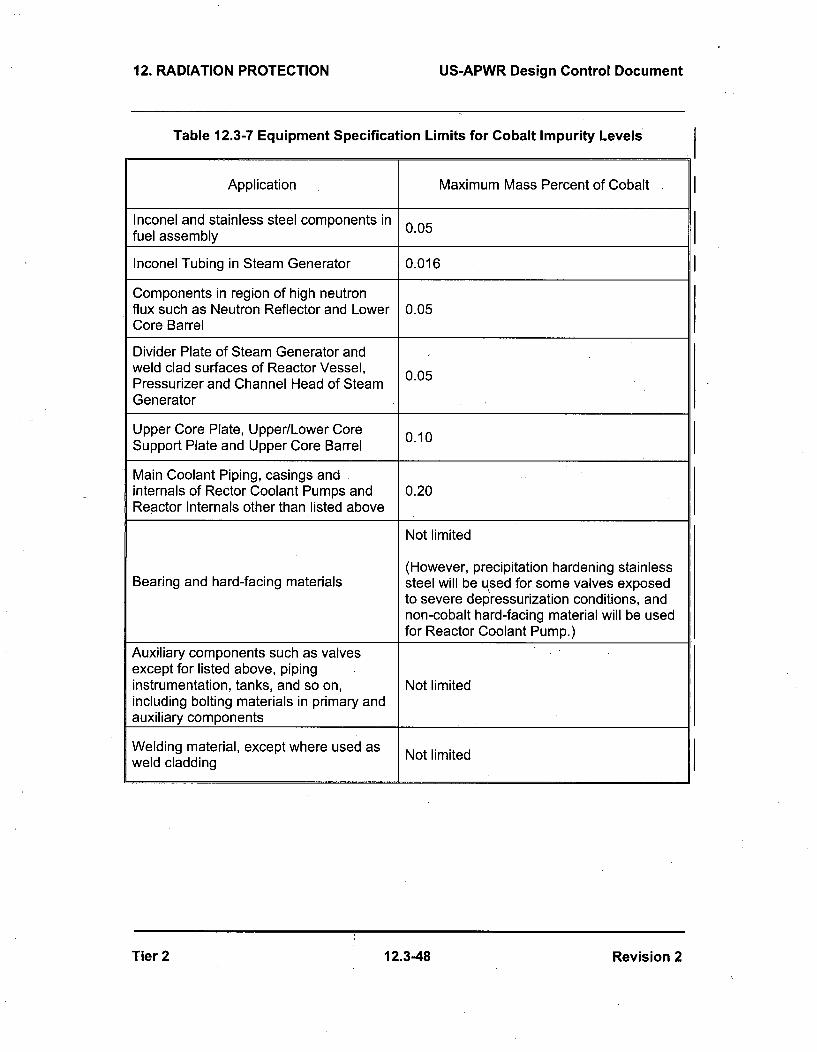
12. RADIATION PROTECTION US-APWR Design Control Document
Table 12.3-7 Equipment Specification Limits for Cobalt Impurity Levels
Application Maximum Mass Percent of Cobalt
Inconel and stainless steel components in 0.05fuel assembly
Inconel Tubing in Steam Generator 0.016
Components in region of high neutronflux such as Neutron Reflector and Lower 0.05Core Barrel
Divider Plate of Steam Generator andweld clad surfaces of Reactor Vessel, 0.05Pressurizer and Channel Head of SteamGenerator
Upper Core Plate, Upper/Lower Core 0.10Support Plate and Upper Core Barrel
Main Coolant Piping, casings andinternals of Rector Coolant Pumps and 0.20Reactor Internals other than listed above
Not limited
(However, precipitation hardening stainlessBearing and hard-facing materials steel will be used for some valves exposed
to severe depressurization conditions, andnon-cobalt hard-facing material will be usedfor Reactor Coolant Pump.)
Auxiliary components such as valvesexcept for listed above, pipinginstrumentation, tanks, and so on, Not limitedincluding bolting materials in primary andauxiliary components
Welding material, except where used as Not limitedweld cladding
Tier 2 12.3-48 Revision 2

U. S. Nuclear Regulatory CommissionCP-200901560TXNB-0906411/11/09
Attachment 4
Response to Request for Additional Information No. 3511 (CP RAI #99)
U. S. Nuclear Regulatory CommissionCP-200901560TXNB-09064,11/11/2009Attachment 4Page 1 of 7
RESPONSE TO REQUEST FOR ADDITIONAL INFORMATION
Comanche Peak Units 3 and 4
Luminant Generation Company LLC
Docket No. 52-034 and 52-035
RAI NO.: 3511 (CP RAI #99)
SRP SECTION: 12.03-12.04 - Radiation Protection Design Features
QUESTIONS for Health Physics Branch (CHPB)
DATE OF RAI ISSUE: 9/30/2009
QUESTION NO.: 12.03-12.04-1
10 CFR 20.1406, Regulatory Guide 4.21, NEI 08-08, IEB 80-10, and NUREG-0800 Standard ReviewPlan (SRP) Sections 12.3-12.4
NUREG-800, Standard Review Plan (SRP) Section 12.3-12.4 requests that the applicant describefeatures that will meet the requirements of 10 CFR 20.1406 for a program to minimize contaminationof the facility and the environment, and the facilitation of the eventual decontamination of the facility.The regulatory position statements of Regulatory Guide 4.21, 'Minimization of Contamination andRadioactive Waste Generation: Life Cycle Planning,' (June 2008) provide guidance related to theprevention and early detection of leakage, which includes barriers to leakage, and maintenance andmonitoring of components important to the prevention of leakage. The appendices of this regulatoryguide, and information provided in documents such as the "Liquid Radioactive Release LessonsLearned Task Force Final Report" indicate that prevention and detection methods must be applied allthe way from the material origination point to the final discharge point noted in the offsite dosecalculation manual (ODCM). NRC Bulletin 80-10 describes events and configurations that resulted incontamination of normally clean systems, by interconnected contaminated systems. The combinedlicense (COL) applicant is responsible for addressing the design, inspection and maintenance featuresprovided to minimize facility contamination for those structures, systems and components provided bythe applicant. Industry experience has shown that extensive environmental or facility and personnelcontamination can occur due to leakage from systems or components such as:
Portions of cooling water return piping located down stream of radioactive waste connectionpoints
Steam and condensate lines containing fluid supplied by the main steam or condensate system,due to the low level tritium content in secondary side water systems.
Fluid systems supplied by recycled Reactor Coolant System water sources, such as the PrimaryMakeup Water Storage Tank.
Interconnections between non-radiological plant systems, such as station air and demineralizedwater, and applicant supplied systems, such as mobile liquid waste processing systems.
HVAC system condensate drains.Piping to and from COL applicant supplied structures, like evaporation ponds.
U. S. Nuclear Regutatory CommissionCP-200901560TXNB-0906411/11/2009Attachment 4Page 2 of 7
Please revise and update the COL FSAR to:a. Describe in Comanche Peak FSAR Chapter 12, the design features, and related inspection and
inspection requirements, to prevent or mitigate contamination of the environment from COLapplicant provided systems, structures and components, that may contain radioactive material,
b. Describe in Table 1.9-201 "Comanche Peak Nuclear Power Plant, Units 3 and 4 Conformancewith Division 1 Regulatory Guides", how Comanche Peak, Units 3 and 4 will comply with 10 CFR20.1406 by use of RG 4.21 or NEI 08-08.
Alternately, describe and justify the specific approaches employed to prevent contamination of theenvironment and facility from COL Applicant provided Systems, Structures or Components containingradioactive material.
ANSWER:
a. The following design, inspection and maintenance features (both general, such as design andinspection features described in the DCD, and site-specific, such as the COL applicant suppliedstructures like the evaporation pond) are incorporated to prevent or mitigate contamination ofthe environment from various SSCs, in accordance with and satisfying RG 4.21 byimplementing NEI 08-08, "Generic FSAR Template Guidance for Life Cycle Minimization ofContamination":
" Heat exchangers containing radioactive fluid are designed with corrosion-resistant materialsand the radioactive fluid is processed through the tube side (DCD Subsection 12.3.1.1.1.2,Item F). On the shell side, the return header has a radiation monitor to isolate the coolingwater system in the event leakage is detected.
" Condenser vacuum pump exhaust is equipped with radiation monitors to close the steamgenerator blowdown isolation valves in the event that radiation level exceeds a pre-determined setpoint (Refer to DCD Subsection 10.3.3, DCD Figure 10.4.2-1, and DCDSubsection 11.5.2.4.2).
" The letdown from the primary coolant is filtered, ion exchanged, evaporated, and recycledthrough the CVCS for plant use. The CVCS employs non-leakage type valves such asdiaphragm-type valves or leak control valves with graphite packing for handling radioactivefluid. For components which cannot structurally employ these types of valves, a leak-offconnection is provided to prevent leakage to atmosphere (Refer to DCD Subsection9.3.4.2.6.26).
" The primary makeup water tanks and refueling water storage auxiliary tank are located in atank house in which the walls and floors are coated with non-porous material to minimizespillage in the event of tank leakage and failure. (Refer to the response to the US-APWRDCD RAI No. 427-2909 Question 12.02-21, submitted to the NRC via MHI letter UAP-HF-09473 dated September 30, 2009) The floor will be sloped towards the drainage pit orfunnel to facilitate the collection of any leakage or spillage from the tank failure. Thedrainage system is also equipped with a liquid detection instrument which provides analarm in the event of a leakage and/or over flow condition to indicate operator action.
" The Liquid Waste Management System (LWMS) and the Solid Waste Management System(SWMS) which employ flexible interconnecting piping for radioactive fluids are designedwith connectors that are incompatible with the connectors for non-radioactive fluids toprevent accidental cross-contamination (Refer to DCD Subsection 11.4.1.4, secondparagraph, fifth bullet).

U. S. Nuclear Regulatory CommissionCP-200901560TXNB-0906411/11/2009Attachment 4Page 3 of 7
For the evaporation pond, piping with leakage detection and inspection ports is used tominimize contamination to the environment. The evaporation pond is designed to have twolayers of high density polyethylene and a leakage detection system [Refer to RAI No. 2747(CP RAI #29) response, submitted to the NRC via letter TXNB-09048 dated September 24,2009 (ML092720676), for details].
b. The FSAR Table 1.6-201 and Table 1.9-202 have been revised to include NEI 08-08 andRG 4.21 compliance, respectively.
Impact on R-COLA
See attached mark-ups for FSAR Draft Revision 1 pages 1.6-2, 1.9-16, 12.5-2, and 12.5-3. The mark-ups also include changes that will be provided as part of the responses to RAI No. 3316 (CP RAI #118)and RAI No. 3318 (CP RAI #119). The use of NEI 08-08 is described in the first sentence of the addedparagraph in Subsection 12.5.4.8 of NEI 07-03A.
Impact on S-COLA
None.
Impact on DCD
None.

Comanche Peak Nuclear Power Plant, Units 3 & 4COL Application
Part 2, FSAR
CP SUP 1.6(1) Table 1.6-201
Material Referenced
FSAR SectionReport Number Title Number
52-021,Docket Number
NEI 07-09A
NEI 07-10A
NEI 07-08
US-APWR Design ControlDocument, Rev. 2
All FSAR Chapters
NEI 07-03A
NEI 08-08
NEI 06-13A
NEI 06-06
NEI 06-09
NEI 04-10
NEI 06-14A
NEI 07-02A
Generic FSAR Template Guidance 11.5for Offsite Dose Calculation ManualProgram Description, Rev.0
Generic FSAR Template Guidance 11.4for Process Control Program, Rev.0
Generic FSAR Template Guidance 12.1for Ensuring That OccupationalRadiation Exposures Are As Low AsIs Reasonably Achievable (ALARA),Rev. 3
Generic FSAR Template Guidance 12.1, 12.5for Radiation Protection ProgramDescription, Rev. 0
Generic FSAR Template Guidance 12.5for Life-Cycle Minimization ofContamination, Rev. 3
Template for an Industry Training 13.2Program Description, Rev. 1
Fitness for Duty Program Guidance 13.7for New Nuclear Power PlantConstruction Sites, Rev. 3
RCOL2_12.03-12.04-1RCOL2_ 2.01-4RCOL2_12.03-12.04-7
Risk-Managed TechnicalSpecifications (RMTS) Guidelines,Rev. 0
16.1, Chapter 19
Risk-Informed Method for Control of 16.1Surveillance Frequencies, Rev. 1
Quality Assurance ProgramDescription, Rev. 0
Generic FSAR Template Guidancefor Maintenance Rule ProgramDescription for Plants LicensedUnder 10 CFR Part 52, Rev. 0
17.5
17.6
1.6-2 1.62 r-aft- Ro'.ision 4

Comanche Peak Nuclear Power Plant, Units 3 & 4COL Application
Part 2, FSAR
CP COL 1.9(1) Table 1.9-202
Comanche Peak Nuclear Power Plant Units 3 & 4 Conformance with Division 4 Regulatory GuidesRG Number RG Title Revision/Date COLA/FSAR Status Corresponding
Chapter/Section
4.7 General Site Suitability Criteria for Revision 2 April Conformance 2.1
4.15
4.21
Nuclear Power Stations
Quality Assurance for RadiologicalMonitoring Programs (Inception throughNormal Operations to LicenseTermination) - Effluent Streams and theEnvironment
Minimization of Contamination andRadioactive Waste Generation:Life-Cycle Planning
1998
Revision 2 July2007
June 2008
2.4.122.4.13.2.5.5
Conformance with exceptions(QA requirements meet existing active radiological 11.5monitoring program for CPNPP Units 1 and 2.)
CTS-00529
RCOL2_12.03-12.04-1Conformance 9.3.4.2.6.26
11.2.3.111.2.3.411.4.1.412.1,312.3.1.1.1.2
1.9-16 1.9-16 Daft Revorioen 4

Comanche Peak Nuclear Power Plant, Units 3 & 4COL Application
Part 2, FSAR
Add the following information after the paragraph in the discussion on RadwasteHandling in Subsection 12.5.4.2 of NEI 07-03A. MAP-12-102
CPNPP Units 3 and 4 have a plan to store temporarily radioactivewastes/materials in Interim Radwaste Storage/Staging Building outside the plantstructures. Entry into the radiologically controlled areas of this building is allowed CTS-00463
only through the issuance of a Radiation Work Permit. Non-radiologicallycontrolled areas allow for general access.
Add the following information after the third paragraph in Subsection 12.5.4.4 ofNEI 07-03A. MAP-12-102
The locations and radiological controls of the radiation zones on plant layoutdrawings are located in DCD Subsection 12.3.1.2. Administrative controls forrestricting access to Very High Radiation Areas are incorporated into plant RCOL2_12.0
procedures which require approvalpfeyided by the Plant Manageres (or designee) 3-12.04-2
appreywlfor each entry. Entry will be controlled through the Radiation Work Permit-(RWP) process. Physical Aaccess controls for Very High Radiation Areas is-centrelledare provided by physical barriers such as lockablethe gates or doorswhich prevent unauthorized access and cntry to thee arcac is all,• ed onlythrough the iscuancc ef a Radiation Work Prmit. It's not necessary to enterthese areas periodically. DCD Subsection 12.3.1.2 includes detailed drawings ofthe very high radiation areas and indicates the physical access controls. Table12.5-201 summarizes the plant areas with the potential to become very highradiation areas. Radiation monitor locations for each area are indicated in DCDSubsection 12.3.4.
Add the following information after the sixth paragraph in Subsection 12.5.4.4 ofNEI 07-03A. I MAP-1 2-102
The gates provide access control of the fuel transfer tube inspection (Very HighRadiation Area) and the area near the seismic gap below the transfer tube.Access control for these areas is controlled by the gates and entry to these areasis allowed only the issuance of a Radiation Work Permit.
Add the following information at the end of Subsection 12.5.4.8 of NEI 07-03A. RCOL2_12.03-12.04-1
In addition, NEI Template 08-08 Revision 3, "Generic FSAR Template Guidance RCOL2_12.0for Life-Cycle Minimization of Contamination" is fully adopted. And also, the 1-4
RCOL2_12.0guidance provided in NEI 08-08 will be used at CPNPP Units 3 and 4 to minimize 3-12.04-7contamination during construction, operation and decommissioning. This willinclude the use of photographs and video records during construction to facilitate
12.5-2 12.5-2 Daft RP;O'AcO~n I
Comanche Peak Nuclear Power Plant, Units 3 & 4COL Application
Part 2, FSAR
updating the conceptual site model for groundwater movement and aid in revising RCOL2_12.0the groundwater monitoring plan post-construction. Final layout drawings, 3-12.04-1photographs, global positioning survey information and video records will be used RCOL2_12.0in assessing the proper location for groundwater monitoring wells. 1-4
RCOL2_12.0
Replace the first and second paragraph in Subsection 12.5.4.12 of NEI 07-03A 3-12.04-7
with the following. MAP-12-102
The radiation protection program and procedures are established, implemented,maintained and reviewed consistent with the 10 CFR 20.1101 and the qualityassurance program referenced in Chapter 17.
12.5-3 w25Daft Reosoe

U. S. Nuclear Regutatory CommissionCP-200901560TXNB-0905411/11/2009
Attachment 5
Response to Request for Additional Information No. 3674 (CP RAI #96)
U. S. Nuclear Regulatory CommissionCP-200901560TXNB-0906411/11/2009Attachment 5Page 1 of 4
RESPONSE TO REQUEST FOR ADDITIONAL INFORMATION
Comanche Peak Units 3 and 4
Luminant Generation Company LLC
Docket No. 52-034 and 52-035
RAI NO.: 3674 (CP RAI #96)
SRP SECTION: 02.04.14 - Technical Specifications and Emergency Operation Requirements
QUESTIONS for Hydrologic Engineering Branch (RHEB)
DATE OF RAI ISSUE: 9/3012009
QUESTION NO.: 02.04.14-1
NUREG-0800, Standard Review Plan (SRP), Chapter 2.4.14, 'Technical Specifications and EmergencyOperation Requirements,' establishes criteria that the NRC staff intends to use to evaluate whether anapplicant meets the NRC's regulations.
Provide a description of the monitoring, notification, and corrective procedures that would ensure thatinterruption of makeup water flow to the essential service water system (ESWS) would trigger actions tomaintain the reliability of the ultimate heat sink (UHS) under all operating or accident conditions, orwould trigger the initiation of shutdown until makeup water flow is restored.
ANSWER:
Makeup water flow to the UHS is assumed lost during design basis events such as failure of themakeup water valve(s) and worst accident scenarios such as a loss of coolant accident coincident witha loss of offsite power (see COLA FSAR Subsection 9.2.5.2).
Flow control valves installed in the UHS basin makeup line control the makeup water flow to the coolingtower basins to replace evaporation and drift losses. Redundant Class 1 E level indicators with low-leveland high-level alarms constantly monitor the basin water level and ensure automatic notification ofreductions in basin water inventory in the event of failure of these valves or interruptions in the watersource. Upon receipt of a low-basin water signal, the blowdown control valve closes automatically andterminates blowdown operations. In addition, the UHS basin inventory is assured through requiredactions and periodic surveillance in Technical Specification 3.7.9.
Impact on R-COLA
None.
Impact on S-COLA
None.

U. S. Nuclear Regulatory CommissionCP-200901 560TXNB-0906411/11/2009Attachment 5Page 2 of 4
Impact on DCD
None.

U. S. Nuclear Regulatory CommissionCP-200901560TXNB-0906411/11/2009Attachment 5Page 3 of 4
RESPONSE TO REQUEST FOR ADDITIONAL INFORMATION
Comanche Peak Units 3 and 4
Luminant Generation Company LLC
Docket No. 52-034 and 52-035
RAI NO.: 3674 (CP RAI #96)
SRP SECTION: 02.04.14 - Technical Specifications and Emergency Operation Requirements
QUESTIONS for Hydrologic Engineering Branch (RHEB)
DATE OF RAI ISSUE: 9/30/2009
QUESTION NO.: 02.04.14-2
NUREG-0800, Standard Review Plan (SRP), Chapter 2.4.14, 'Technical Specifications and EmergencyOperation Requirements,' establishes criteria that the NRC staff intends to use to evaluate whether anapplicant meets the NRC's regulations.
Provide a description of how sufficient cooling capacity and safety within the UHS and ESWS would bemaintained during the failure of two or more cooling tower basins as a result of a single hydrologic eventor other accident representing a single failure.
ANSWER:
The safety-related plant elevation (822 ft msl) is higher than the design basis flood elevation under theworst potential floods, hence flooding around the site will not have an adverse impact on the safety-related structures. Low water conditions from surges, seiches, or tsunamis are also unlikely due to theplant's inland location and site characteristics. There are no safety-related facilities that could beaffected by ice-induced low flow at CPNPP Units 3 and 4. The freezing protection is described inSubsection 9.2.1.3. Droughts do not affect the UHS cooling capability because of the four 33.3%capacity basins that do not require external water makeup for up to 30 days under the worst designbasis accident conditions. A more thorough discussion is given in FSAR Subsections 2.4.2 through2.4.11 demonstrating that no single hydrologic event will result in the failure of two or more coolingtower basins.
The UHS and UHS-related structures, including the cooling tower basins, are designed to SeismicCategory I and Equipment Class 3 requirements. Conformance to these requirements protects thesestructures from the effects of natural phenomena events, including those mentioned above, seismic,abnormal and accident conditions.
A single failure in both systems occurring after an accident does not challenge the UHS and ESWScooling capability. At this condition, only two UHS and two ESWS trains are required to sufficientlyremove the design heat load from the systems to be cooled by these structures. This assures thecooling capability and, safety within the two systems.
U. S. Nuclear Regulatory CommissionCP-200901560TXNB-0906411/11/2009Attachment 5Page 4 of 4
The Technical Specifications for the ESWS and the UHS in COLA Part 4, Specifications 3.7.8 and
3.7.9, respectively, address the discussion given above.
Impact on R-COLA
None.
Impact on S-COLA
None.
Impact on DCD
None.

U. S. Nuclear ReguLatory CommissionCP-200901560TXNB-0906411/11/2009
Attachment 6
Response to Request for Additional Information No. 3675 (CP RAI #95)

U. S. Nuclear Regulatory CommissionCP-200901560TXNB-0906411/11/2009Attachment 6Page 1 of 15
RESPONSE TO REQUEST FOR ADDITIONAL INFORMATION
Comanche Peak Units 3 and 4
Luminant Generation Company LLC
Docket No. 52-034 and 52-035
RAI NO.: 3675 (CP RAI #95)
SRP SECTION: 02.04 - Hydrology
QUESTIONS for Hydrologic Engineering Branch (RHEB)
DATE OF RAI ISSUE: 9/30/2009
QUESTION NO.: 02.04-1
In the subsections of Section 2.4 of Comanche Peak FSAR the applicant has stated thefollowing:
2.4.1 Hydrologic DescriptionCP COL 2.4(1) Replace the content of DCD Subsection 2.4.1 with the following.
2.4.2 FloodsCP COL 2.4(1) Replace the content of DCD Subsection 2.4.2 with the following.
2.4.3 Probable Maximum FloodCP COL 2.4(1) Replace the content of DCD Subsection 2.4.3 with the following.
2.4.4 Potential Dam FailuresCP COL 2.4(1) Replace the content of DCD Subsection 2.4.4 with the following.
2.4.5 Probable Maximum Surge and Seiche FloodingCP COL 2.4(1) Replace the content of DCD Subsection 2.4.5 with the following.
2.4.6 Probable Maximum Tsunami HazardCP COL 2.4(1) Replace the content of DCD Subsection 2.4.6 with the following.
2.4.7 Ice EffectsCP COL 2.4(1) Replace the content of DCD Subsection 2.4.7 with the following.
2.4.8 Cooling Water Canals and ReservoirsCP COL 2.4(1) Replace the content of DCD Subsection 2.4.8 with the following.
2.4.9 Channel DiversionsCP COL 2.4(1) Replace the content of DCD Subsection 2.4.9 with the following.
2.4.10 Flooding Protection RequirementsCP COL 2.4(1) Replace the content of DCD Subsection 2.4.10 with the following.
U. S. Nuclear Regulatory CommissionCP-200901560TXNB-0906411/11/2009Attachment 6Page 2 of 15
2.4.11 Low Water ConsiderationsCP COL 2.4(1) Add the following after the second paragraph of DCD Subsection 2.4.11..
2.4.12 GroundwaterCP COL 2.4(1) Replace the content of DCD Subsection 2.4.12 with the following.
2.4.13 Accidental Releases of Radioactive Liquid Effluent in Ground and Surface watersCP COL 2.4(1) Add the following at the end of the DCD Subsection 2.4.13.
2.4.14 Technical Specification and Emergency Operation RequirementsCP COL 2.4(1) Add the following after the paragraph in DCD Subsection 2.4.14.
2.4.15 Combined License InformationCP COL 2.4(1) Replace the content of DCD Subsection 2.4.15 with the following.2.4(1) Hydrologic Related EventsThis COL item is addressed in Subsections 2.4.1, 2.4.2, 2.4.3, 2.4.4, 2.4.5, 2.4.6, 2.4.7, 2.4.8, 2.4.9,2.4.10, 2.4.11, 2.4.12, 2.4.13 and 2.4.14 along with the associated tables and figures.
2.4.16 ReferencesCP SUP2.4(1) Add the following references after the last DCD reference.
While the purpose of a COLA is to incorporate by reference portions of the DCD and include sitespecific information and analyses, the Comanche Peak COLA FSAR appears to be trying to update theUS-APWR DCD. Provide a description and/or correction in the FSAR to correct the irregularity in therecommended action of the Comanche Peak R-COLA. This is important in view of the fact thatComanche Peak is the Reference COLA (R-COLA) and a subsequent COLA (S-COLA) will beincorporating by reference portions of the R-COLA.
ANSWER:
There are two segments to this RAI and each segment requires a different type of response.
1) For FSAR Subsections 2.4.11,2.4.13, 2.4.14 and 2.4.16, the subsections, as written, comply withthe intent of COLA format. At the beginning of FSAR Section 2.4 there is the standard incorporate byreference (IBR) statement and each of these subsections begins with "Add the following..." As a result,the DCD content for those subsections is being accepted and supplemented by the site-specificmaterial.
2) The other segment concerns the subsections that begin with "Replace the content..." Thesesubsections were written that way because of the manner in which DCD Section 2.4 was written. InRevision 1 of the DCD, Section 2.4 was revised to closely align with Regulatory Guide (RG) 1.206. Infact, many of the DCD subsections simply paraphrase the RG and provide a description of what thesubsection will contain. When the site-specific material was prepared, the required content of thesubsection was addressed. These subsections were not considered to be IBR subsections because thecorresponding DCD segment contained no generic information applicable to all applicants who elect toutilize the US-APWR design.
The FSAR Section 2.4 subsections beginning with, "Replace the content..." have been revised to use,"Add the following..." so that the same format is used throughout the section.
U. S. Nuclear ReguLatory CommissionCP-200901560TXNB-0906411/11/2009Attachment 6Page 3 of 15
Impact on R-COLA
See attached marked-up FSAR Draft Revision 1 pages 2.4-2, 2.4-14, 2.4-20, 2.4-26, 2.4-32, 2.4-34,
2.4-35, 2.4-37, 2.4-38, 2.4-39, 2.4-45, and 2.4-78.
Impact on S-COLA
None.
Impact on DCD
None.

Comanche Peak Nuclear Power Plant, Units 3 & 4COL Application
Part 2, FSAR
2.4.1 Hydrologic Description
CP COL 2.4(1) RcplaGcc thc contcntAdd the following at the end of DCD Subsection 2.4.1 with the I RCOL2_02.0
fellew.. . 1 4-1
This subsection describes regional and site hydrological conditions, specificallysurface water and groundwater characteristics. Information provided in thissubsection includes descriptions of the site and features, hydrosphere, hydrologiccharacteristics, drainage, dams and reservoirs, proposed water managementchanges, and surface water users.
2.4.1.1 Site and Facilities
Comanche Peak Nuclear Power Plant (CPNPP) Units 3 and 4 are located on thewestern end of a peninsula formed by the southern shore of Squaw CreekReservoir (SCR) and the CPNPP Units 1 and 2 Safe Shutdown Impoundment,approximately 0.49 mi west-northwest of CPNPP Units 1 and 2 in SomervellCounty, Texas. The CPNPP site is located in Somervell and Hood Counties,Texas approximately 5.2 mi north-northwest of the town of Glen Rose, Texas(Figure 2.1-202).
CPNPP Units 3 and 4 are located approximately 0.49 mi west-northwest ofCPNPP Units 1 and 2 as shown in Figure 2.1-201 and utilize mechanical draftcooling towers for circulating and service water system cooling. Cooling watercomes from Lake Granbury located approximately 7.13 mi north-northeast of theCPNPP site.
Maximum relief in the CPNPP site area is approximately 220 ft, with elevationsranging from 640 ft to 860 ft above sea level, with slopes that are typically steep,ranging from 15 to 30 degrees or more, and generally exhibiting a stair-steppedappearance. Rock outcrops of limestone and claystone comprise approximately40 to 60 percent of these slopes. The remaining areas, including the higherflat-topped plateau remnants, are mantled by a thin cover of soil, which at thesurface generally consists of silt and sand (Reference 2.4-201). The standardplant gfadefloor elevation of the safety-related facilities is established at 823 ft CTS-00590above msl. The center of the nonsafety-related mechanical draft cooling towers islocated about 1,800 ft to the northwest of the CPNPP Unit 3 and 4 center point ata grade elevation of 850 ft msl (Figure 2.1-201). Locations and topographicprofiles showing the relationship between the CPNPP site, SCR, and LakeGranbury are illustrated on Figures 2.4.1-201 and 2.4.1-202. Grading anddrainage improvements are illustrated on Figure 2.4.2-202.
Lake Granbury, the source of cooling water for the cooling tower system, isdiscussed in detail in Subsection 2.4.1.2. Cooling water is expected to bewithdrawn by an intake structure located approximately 1.31 mi upstream from theDeCordova Bend dam. The cooling water is pumped to the CPNPP Units 3 and 4cooling system through two pipelines, and the blowdown water from the coolingwater system is discharged through two separate pipelines back to Lake Granbury
2.4-2 2 2aft Re. mvmmn 1
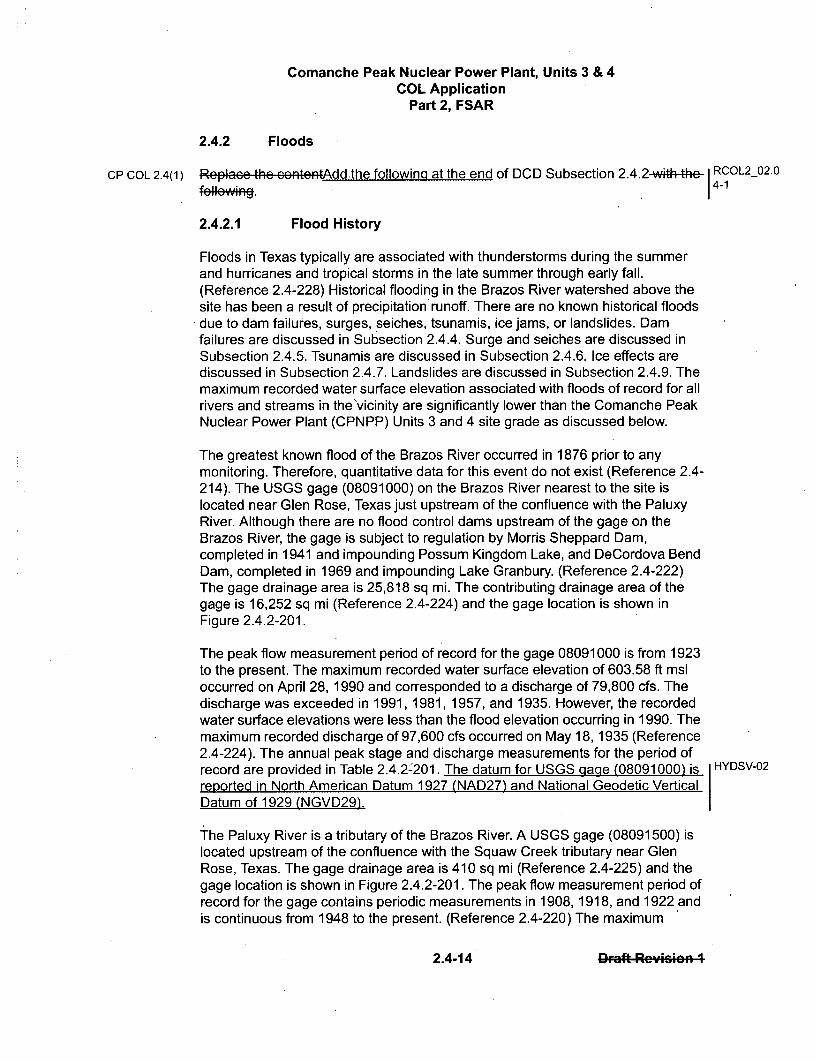
Comanche Peak Nuclear Power Plant, Units 3 & 4COL Application
Part 2, FSAR
2.4.2 Floods
CP COL 2.4(1) Rplac-, thc contcntAdd the following at the end of DCD Subsection 2.4.2-with-4he- RCOL2O02.0fall....'•14-1
2.4.2.1 Flood History
Floods in Texas typically are associated with thunderstorms during the summerand hurricanes and tropical storms in the late summer through early fall.(Reference 2.4-228) Historical flooding in the Brazos River watershed above thesite has been a result of precipitation runoff. There are no known historical floodsdue to dam failures, surges, seiches, tsunamis, ice jams, or landslides. Damfailures are discussed in Subsection 2.4.4. Surge and seiches are discussed inSubsection 2.4.5. Tsunamis are discussed in Subsection 2.4.6. Ice effects arediscussed in Subsection 2.4.7. Landslides are discussed in Subsection 2.4.9. Themaximum recorded water surface elevation associated with floods of record for allrivers and streams in the'vicinity are significantly lower than the Comanche PeakNuclear Power Plant (CPNPP) Units 3 and 4 site grade as discussed below.
The greatest known flood of the Brazos River occurred in 1876 prior to anymonitoring. Therefore, quantitative data for this event do not exist (Reference 2.4-214). The USGS gage (08091000) on the Brazos River nearest to the site islocated near Glen Rose, Texas just upstream of the confluence with the PaluxyRiver. Although there are no flood control dams upstream of the gage on theBrazos River, the gage is subject to regulation by Morris Sheppard Dam,completed in 1941 and impounding Possum Kingdom Lake, and DeCordova BendDam, completed in 1969 and impounding Lake Granbury. (Reference 2.4-222)The gage drainage area is 25,818 sq mi. The contributing drainage area of thegage is 16,252 sq mi (Reference 2.4-224) and the gage location is shown inFigure 2.4.2-201.
The peak flow measurement period of record for the gage 08091000 is from 1923to the present. The maximum recorded water surface elevation of 603.58 ft msloccurred on April 28, 1990 and corresponded to a discharge of 79,800 cfs. Thedischarge was exceeded in 1991, 1981, 1957, and 1935. However, the recordedwater surface elevations were less than the flood elevation occurring in 1990. Themaximum recorded discharge of 97,600 cfs occurred on May 18, 1935 (Reference2.4-224). The annual peak stage and discharge measurements for the period ofrecord are provided in Table 2.4.2:201. The datum for USGS gage (08091000) is HYDSV-02
reported in North American Datum 1927 (NAD27) and National Geodetic VerticalDatum of 1929 (NGVD29).
The Paluxy River is a tributary of the Brazos River. A USGS gage (08091500) islocated upstream of the confluence with the Squaw Creek tributary near GlenRose, Texas. The gage drainage area is 410 sq mi (Reference 2.4-225) and thegage location is shown in Figure 2.4.2-201. The peak flow measurement period ofrecord for the gage contains periodic measurements in 1908, 1918, and 1922 andis continuous from 1948 to the present. (Reference 2.4-220) The maximum
2.4-14 2.4-14Draft Rc':icion 4

Comanche Peak Nuclear Power Plant, Units 3 & 4COL Application
Part 2, FSAR
2.4.3 Probable Maximum Flood
CP COL 2.4(1) Rcplacc thc contcnt,4dd the following at the end of DCD Subsection 2.4.3 with the I RCOL2_02.0
The guidance in Appendix A of the U.S. Nuclear Regulatory Commission (NRC)Regulatory Guide 1.59 was followed in determining the PMF by applying theguidance of ANSI/ANS-2.8-1992 (Reference 2.4-229). ANSI/ANS-2.8-1992 wasissued to supersede ANSI N170-1976, which is referred to by RegulatoryGuide 1.59. ANSI/ANS-2.8-1992 is the latest available standard.
The PMF was determined for the Squaw Creek watershed and routed through theSCR to determine a water surface elevation of 78&9790.9 ft msl. The PMF for the HYDSV-06
Paluxy River watershed at the confluence with the Brazos River was also HYDSV-07
examined. The PMF for the Paluxy River and the Squaw Creek watersheds wascombined with the Brazos River dam failure flood flow to determine any backwatereffects that may affect the site. The Brazos River dam failure flood flow isdescribed in Subsection 2.4.4 and includes the PMF for the Brazos River. Theresulting water surface elevation downstream of the Squaw Creek Dam is76.08755.21 ft msl. I HYDSV-06
HYDSV-07
The CPNPP Units 3 and 4 safety-related facilities are located at elevation 822 ftmsl. Therefore, PMF on rivers and streams does not present any potentialhazards for CPNPP Units 3 and 4 safety-related facilities.
2.4.3.1 Probable Maximum Precipitation
The PMP is defined by HMR 51 (Reference 2.4-218) and HMR 52 (Reference 2.4-219). HMR 53 (Reference 2.4-230) may be used to derive seasonal estimates ofthe PMP. The PMP was determined for the Squaw Creek and the Paluxy Riverwatersheds. Using the location of the watersheds, HMR 51 PMP charts are usedto determine generalized estimates of the all-season PMP for drainage areas from10 to 20,000 sq mi for durations from 6 to 72 hr. The resulting depth-area-duration(DAD) values are shown in Table 2:4.3-201.
HMR 52 is used to determine the aerial distribution of PMP estimates derived fromHMR 51. The recommended elliptical isohyetal pattern from HMR 52, shown inFigure 2.4.3-201, is used for the watersheds. The watershed model, combiningboth watersheds, contains 4 subbasins and is shown in Figure 2.4.3-202. Thewatershed model is discussed in detail in Subsection 2.4.3.3.
HMR 52 computer software (Reference 2.4-231), developed by USACE, is usedto determine the optimum storm size and orientation to produce the greatest PMPover the watersheds using the HMR 51 derived DAD table. Several storm centerswere examined for each watershed to determine the critical storm center.
In accordance with Appendix A of Regulatory Guide 1.59, the 72-hr PMP storm iscombined with an antecedent storm equal to 40 percent of the PMP. Therefore,
2.4-20 2W0Daft Rcviciow I
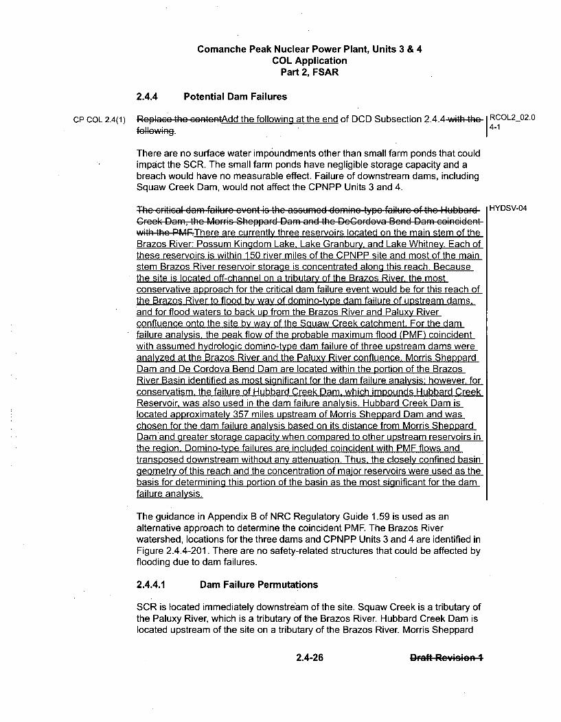
Comanche Peak Nuclear Power Plant, Units 3 & 4COL Application
Part 2, FSAR
2.4.4 Potential Dam Failures
CP COL 2.4(1) RP-I th,.I contentLndd the following at the end of DCD Subsection 2.4.4w,,,hlI It t RCOL2_02.0#•11....;•14-1
There are no surface water impoundments other than small farm ponds that couldimpact the SCR. The small farm ponds have negligible storage capacity and abreach would have no measurable effect. Failure of downstream dams, includingSquaw Creek Dam, would not affect the CPNPP Units 3 and 4.
Th" e";iti; l d.• fili ... R. t i" th" . .. . .d demone typ" f.ili i•;r . .f th" U,,hhubb' HYDSV-04
Crock( Dam, the Morric Sheppard Dam and the De~ordeya Bend Dam coinecidentwith the44PF.There are currently three reservoirs located on the main stem of theBrazos River: Possum Kingdom Lake, Lake Granbury. and Lake Whitney. Each ofthese reservoirs is within 150 river miles of the CPNPP site and most of the mainstem Brazos River reservoir storage is concentrated along this reach. Becausethe site is located off-channel on a tributary of the Brazos River, the mostconservative approach for the critical dam failure event would be for this reach ofthe Brazos River to flood by way of domino-type dam failure of upstream dams,and for flood waters to back up from the Brazos River and Paluxy Riverconfluence onto the site by way of the Squaw Creek catchment. For the damfailure analysis, the peak flow of the probable maximum flood (PMF) coincidentwith assumed hydrologic domino-type dam failure of three upstream dams wereanalyzed at the Brazos River and the Paluxy River confluence. Morris SheppardDam and De Cordova Bend Dam are located within the portion of the BrazosRiver Basin identified as most significant for the dam failure analysis: however, forconservatism, the failure of Hubbard Creek Dam, which impounds Hubbard CreekReservoir, was also used in the dam failure analysis. Hubbard Creek Dam islocated approximately 357 miles upstream of Morris Sheppard Dam and waschosen for the dam failure analysis based on its distance from Morris SheppardDamrand greater storage capacity when compared to other upstream reservoirs inthe region. Domino-type failures are included coincident with PMF flows andtransposed downstream without any attenuation. Thus, the closely confined basingeometry of this reach and the concentration of major reservoirs were used as -thebasis for determining this portion of the basin as the most significant for the damfailure analysis.
The guidance in Appendix B of NRC Regulatory Guide 1.59 is used as analternative approach to determine the coincident PMF. The Brazos Riverwatershed, locations for the three dams and CPNPP Units 3 and 4 are identified inFigure 2.4.4-201. There are no safety-related structures that could be affected byflooding due to dam failures.
2.4.4.1 Dam Failure Permutations
SCR is located immediately downstream of the site. Squaw Creek is a tributary ofthe Paluxy River, which is a tributary of the Brazos River. Hubbard Creek Dam islocated upstream of the site on a tributary of the Brazos River. Morris Sheppard
2.4-26 2.4-26 r-aft RcpuWin I
Comanche Peak Nuclear Power Plant, Units 3 & 4COL Application
Part 2, FSAR
2.4.5 Probable Maximum Surge and Seiche Flooding
CP COL 2.4(1) Replaco thc contcntAdd the following at the end of DCD Subsection 2.4.5 with the RCOL2_02.0,l~rI r-,tA,:n~i4-1
According to the NRC Regulatory Guide 1.59, "Design Basis Floods for NuclearPower Plants," probable maximum surge and seiche flooding is considered basedon a probable maximum hurricane (PMH), probable maximum windstorm(PMWS), or moving squall line. (Reference 2.4-229) The region of occurrence fora PMH is along U.S. coastline areas. For a PMWS, the region of occurrence isalong coastline areas and large bodies of water such as the Great Lakes. Amoving squall is considered for the Great Lakes region.
According to USACE EM 1110-2-1100 (Reference 2.4-235) guidelines,meteorological wind systems generated by thunderstorms and frontal squall linescan generate waves up to 16.4 ft high for inland waters. Additionally, mesoscaleconvective complex wind systems affecting inland waters are fetch-limited andbased on wind speeds of up to about 66 fps or 45 mph. Similar wind speeds areused to determine the coincident wind-generated wave activity discussed inSubsection 2.4.3. The coincident wind wave activity, including wave setup, results HYDSV-11
in maximum runup of 16.9 ft. The maximum wind setup is estimated to be 0.07 ft.Therefore, the total water surface elevation increase due to wind wave activity isestimated to be 16.97 ft. The resulting PMF coincident with wind wave activityelevation is 807.87 ft msl.
The USACE guideline procedure for geologic hazard evaluations considersseiche waves greater than 7 ft to be rare. (Reference 2.4-242) The seiche hazardcan be screened out for sites located more than 7 ft above the adjacent waterbody.
CPNPP Units 3 and 4 are located approximately 275 mi inland from the Gulf ofMexico. CPNPP Units 3 and 4 safety-related facilities are located at the plant i HYDSV-03
grade level elevation of 822 ft msl. A surge due to a PMH event would not causeflooding at the site.
SCR does not connect directly with any of the water bodies considered for suchmeteorological events associated with surge and seiche flooding. Because of theinland location and elevation characteristics, CPNPP Units 3 and 4 safety-relatedfacilities are not at risk from surge and seiche flooding. Resonance wavephenomena including oscillations of waves at natural periodicity, lake reflection,and harbor resonance are traditionally characteristics of harbors, estuaries, andlarge lakes and not associated with river settings. Any effects on the Squaw- CTS-00817
GeekSCR produced by similar phenomena would not affect CPNPP Units 3 and4.
Seismic-induced waves are not plausible for the SCR. Subsection 2.5.3 indicates HYDSV-10
there are no capable faults, and there is no potential for non-tectonic fault rapturewithin the 25 mi radius of the CPNPP Units 3 and 4. Additionally, there is no
2.4-32 2.4-32 Draft Rc':Ision 1
Comanche Peak Nuclear Power Plant, Units 3 & 4COL Application
Part 2, FSAR
2.4.6 Probable Maximum Tsunami Hazards
CP COL 2.4(1) Rcplac the contcntAdd the following at the end of DCD Subsection 2.4.6wioh th t I RCOL2_02.0
fel,.W-t1 . 1 4-1
Tsunami risk in the Gulf Coast region, primarily the Caribbean, has been studiedto some degree, but no specific hazard maps have been developed for the GulfCoast at this time. The USACE has developed a general tsunami risk map(Reference 2.4-242), as shown in Figure 2.4.6-201. The Gulf Coast is located inZone 1, which corresponds to a wave height of 5 ft.
According to the National Oceanic and Atmospheric Administration's tsunamidatabase (Reference 2.4-243), the maximum recorded tsunami wave height alongthe Gulf Coast or East Coast is about 20 ft. This height was recorded at DaytonaBeach, Florida, on July 3, 1992. The database notes that the wave was probablymeteorologically induced.
According to a recent USGS study (Reference 2.4-244), very little is known abouta landslide-generated tsunami threat from the Mexican coast. Tsunamisgenerated by earthquakes do not appear to impact the Gulf of Mexico coast.CPNPP Units 3 and 4 are located approximately 275 mi inland from the GulfCoast. CPNPP Units 3 and 4 safety-related facilities are located at elevation 822 ftmsl. Because of their inland location and elevation, CPNPP Units 3 and 4 safety-related facilities would not be at risk from tsunami flooding.
Landslide-induced waves are not plausible for SCR. As discussed in Subsection HYDSV-12
2.5.5. the slope stability analysis indicates stable permanent slopes, and therefore HYDSV-13
hill slope failure-induced waves are not plausible for SCR.
Seismic-induced waves are not plausible for SCR. Subsection 2.5.3 states thereare no capable faults and there is no potential for non-tectonic fault rapture withinthe 25 mi radius of the CPNPP Units 3 and 4. Additionally, there is no potential fortectonic or non-tectonic deformation within the 5 mi radius of the CPNPP Units 3and 4. The geologic and seismic characteristics for the CPNPP Units 3 and 4 aredescribed in Section 2.5.
2.4-34 2.4-34 Daft Reyicion 1
Comanche Peak Nuclear Power Plant, Units 3 & 4COL Application
Part 2, FSAR
2.4.7 Ice Effects
CP COL 2.4(1) RoplaGce the contcntAdd the following at the end of DCD Subsection 2.4.7-with-the- I RCOL2 02.0fe IIew. . . 1 4-1 -
According to the EPA STOrage and RETrieval (STORET) database, two gagingstations located on the SCR and its tributaries recorded water temperatures fordifferent periods between 1973 and 1985. The lowest recorded watertemperatures range from 41.9'F to 50'F. The lowest recordings, 41.9°F, occurredon February 10, 1982 at station 11555, Squaw Creek and State Highway 144 (SH144), Northeast of Glen Rose. (Reference 2.4-245)
Gaging station 11856 is located on Brazos River and gaging station 11976 islocated on Paluxy River. The gaging station 11856 on Brazos River at U.S.Highway 67 (US 67) recorded water temperatures from 1968 to 1998. The lowestrecorded water temperature at this station was 39.02'F. (Reference 2.4-245) Thegaging station 11976 on Paluxy River in City Park recorded water temperaturesfrom 1973 to 1996. The lowest recorded water temperature at this station was39.2 0F. (Reference 2.4-245) This data suggests that Squaw Creek watertemperatures generally remain above the freezing point. The recordings aresummarized in Table 2.4.7-201.
According to the USACE, ice jams occur in 36 states, primarily in the northern tierof the United States. (Reference 2.4-246) (Figure 2.4.7-201) Texas is not includedin this coverage. USACE Cold Regions Research and Engineering Laboratoryhistorical ice jam database (Reference 2.4-247) indicates no ice jams for SquawCreek. However, the USACE ice jam database reports that Brazos River wasobstructed by rough ice at Rainbow near Glen Rose, Texas, on January 22-23and January 25-28, 1940, with flood stage of 20 ft. (Reference 2.4-247)
CPNPP Units 3 and 4 safety-related facilities are located at elevation 822 ft msl.The SCR spillway elevation is 775 ft msl (Reference 2.4-214). The maximumwater surface elevation during a probable maximum flood event is at 788.9790.9 ft HYDSV-14msl, which is more than 30 ft below the CPNPP Units 3 and 4 safety-relatedfacilities. The possibility of inundating CPNPP Units 3 and 4 safety-relatedfacilities due to an ice jam is remote.
Meteorological records from the Southern Regional Climate Center (SRCC) wereexamined for areas in the vicinity of CPNPP Units 3 and 4. Records indicate thatDecember and January have the coldest temperatures. For the available period ofrecord from 1971 to 2000, the climate station at Dallas/Fort Worth has a recordedmonthly average minimum temperature of 34°F, occurring in January. (Reference2.4-248)
According to the USACE, frazil ice forms in supercooled turbulent water in riversand lakes. (Reference 2.4-246) Anchor ice is defined as frazil ice attached to theriver bottom, irrespective of the nature of its formation. The potential for freezing(i.e., frazil or anchor ice) and subsequent ice jams on the Squaw Creek and
2.4-35 2.4-35 Drft Rc':Oieio 4
Comanche Peak Nuclear Power Plant, Units 3 & 4COL Application
Part 2, FSAR
2.4.8 Cooling Water Canals and Reservoirs
CP COL 2.4(1) Rcplacc the contcntAdd the following at the end of DCD Subsection 2.4.8 with the- RCOL2 02.0
f• E11W.. . 14-1
There are no current or proposed safety-related cooling water canals or reservoirsrequired for CPNPP Units 3 and 4. The ultimate heat sink (UHS) is part of theessential (sometimes called emergency) service water system (ESWS). Eachunit's ESWS consists of four wet mechanical draft cooling towers, each providing50 percent cooling capacity. Each cooling tower consists of an ESW pump andbasin transfer pump and is located over a basin. Each basin is designed to hold33-1/3 percent of the cooling water inventory to allow safe shutdown up to 30 daysafter an accident without makeup. The above data indicates that the UHS doesnot rely on cooling water canals or reservoirs and is not dependent on a stream,river, estuary, lake, or ocean. Therefore, no warning of impending low flow fromthe lake water makeup system is required. Low lake water conditions would notaffect the ability of the emergency cooling water systems and the UHS to providethe required cooling for emergency conditions. The UHS would not be affected bylow water conditions. CPNPP Units 3 and 4 and UHS are capable of withstandingflooding events as described in Subsections 2.4.2 through Subsection 2.4.7.
2.4-37 Draft Rc8.-icin 1

Comanche Peak Nuclear Power Plant, Units 3 & 4COL Application
Part 2, FSAR
2.4.9 Channel Diversions
CP COL 2.4(1) Replace the contentAdd the following at the end of DCD Subsection 2.4.9 with the I RCOL2_02.0
feIIew. . 1 4-1
The Squaw Creek watershed does not contain any significant structures upstreamof the Squaw Creek Dam. The Brazos River contains several tributary andinstream dams, including DeCordova Bend Dam impounding Lake Granbury.Lake Granbury is the major source of normal makeup cooling water. LakeGranbury is not used as a safety-related water supply source.
The UHS is part of the ESWS. Each unit's ESWS consists of four wet mechanicaldraft cooling towers, each providing 50 percent cooling capacity. Each coolingtower consists of an ESW pump and basin transfer pump and is located over abasin. Each basin is designed to hold 33-1/3 percent of the cooling waterinventory to allow safe shutdown up to 30 days after an accident without makeup.Therefore, channel diversion can not adversely affect CPNPP Units 3 and 4safety-related structures or systems. Additional details are provided in Subsection2.4.11. The potential for ice-induced diversion and flooding is discussed inSubsection 2.4.7. Geologic and seismic characteristics of the region arediscussed in Section 2.5.
There is no evidence suggesting there have been significant historical diversionsor realignments of Squaw Creek or the Brazos River. The topography does notsuggest potential diversions. The streams and rivers in the region arecharacterized by traditional shaped valleys with no steep, unstable side slopesthat could contribute to landslide cutoffs or diversions. There is no evidence ofice-induced channel diversion.
As identified in Subsection 2.5.1.2.5.4, there is no evidence of active karstconditions and related subsidence within the CPNPP site or in the surroundingarea. Furthermore, Subsection 2.5.1.2.5.5 identifies that withdrawal ofgroundwater from aquifers beneath the site does not pose a risk of subsidence atthe current withdrawal rates. Therefore, channel diversion due to subsidence isnot expected.
Channel diversion due to geothermal activity was also investigated and is notexpected. The greatest potential for geothermal energy exists in areas of aboveaverage heat flow, generally the result of recent volcanic activity or activetectonics. East of the Rocky Mountains is characterized by average heat flow(Reference 2.4-249). The area is also relatively tectonically stable and hasexperienced no volcanic activity recent enough to produce heat fromcrystallization (Reference 2.4-250). No thermal anomalies east of the RockyMountains are attributed to young-to-contemporary volcanic or other igneousactivity (Reference 2.4-251).
2.4-38 2-8Draft Rcv•in- 4

Comanche Peak Nuclear Power Plant, Units 3 & 4COL Application
Part 2, FSAR
2.4.10 Flooding Protection Requirements
CP COL 2.4(1) Roplaco the contoztAdd the following at the end of DCD Subsection 2.4.10with I RCOL2_02.0the. ellew-i•:•. 4-1
CPNPP Units 3 and 4 safety-related facilities are not exposed to flooding from allevents identified in Subsection 2.4.2. The critical flooding event is identified inSubsection 2.4.2 and discussed in detail in Subsection 2.4.3. The maximum flood
.level is a result of the probable maximum precipitation on the Squaw Creekwatershed and includes the effects of coincident wind wave activity. Based on thedesign information provided in the referenced subsections, flood protectionmeasures and emergency procedures to address flood protection are notrequired.
2.4-39 2-9Draft Rev•icin 1

Comanche Peak Nuclear Power Plant, Units 3 & 4COL Application
Part 2, FSAR
2.4.12 Groundwater
CP COL 2.4(1) Rcplarcc the contneAdd thefollowing at the end of DCD Subsection 2.4.12-with- I RCOL2 02.0
the .fel . 14-
This subsection provides a summary of the groundwater data collected for theCPNPP Combined Operating License (COL) application.
2.4.12.1 Description and On-Site Use
This subsection describes regional and local aquifers, formations, sources andsinks, types of groundwater use, wells, pumps, storage facilities, and flowrequirements for CPNPP. Groundwater is not used as an operational orsafety-related source of water for CPNPP Units 3 and 4, and Luminant hasimplemented a conservation plan for future groundwater withdrawals at theCPNPP site. During construction of CPNPP Units 3 and 4, and during operation ofCPNPP Units 1 through 4, potable water is to be supplied by the SomervellCounty Water District's water supply system. Water for temporary fire protection,concrete batching, and other construction uses is expected to be supplied by theSomervell County Water District.
2.4.12.1.1 Regional Aquifers, Formations, Sources, and Sinks
The CPNPP site lies within the Brazos River Basin of the Comanche Plateausubdivision of the Central Texas Section of the Great Plains PhysiographicProvince. The relationship of the site to these features and to other physiographicprovinces in the region is shown on Figure 2.4.12-201. To the north is the CentralLowland Physiographic Province; to the east is the Coastal Plain PhysiographicProvince; and to the south is the Great Plains Province. The boundary separatingthe Great Plains Province from the Coastal Plain Province coincides with thecontact of the upper and lower Cretaceous formations on which the CPNPP site islocated.
Maximum relief in the site area is approximately 220 feet (ft), with elevationsranging from 640 ft to 860 ft above sea level with slopes that are typically steep,ranging from 15 to 30 degrees or more, and generally exhibits a stair-steppedappearance. Rock outcrops of limestone and claystone comprise approximately40 to 60 percent of these slopes. The remaining areas, including the higherflat-topped plateau remnants, are mantled by a thin cover of soil, which at thesurface generally consists of silt and sand (Reference 2.4-201).
Portions of six major and nine minor aquifers extend into the Brazos Region GArea (Reference 2.4-208). Brazos Region G is a 37-county planning area, whichextends generally along the Brazos River from Kent, Stonewall, and Knoxcounties in the northwest to Washington and Lee counties in the southeast. TheCPNPP site is located on outcrops of the Trinity Group aquifer, which occursmostly in Callahan, Eastland, Erath, Hood, Somervell, Comanche, Hamilton,Coryell, and Lampasas counties. The confined aquifer area is mostly.in Johnson,
2.4-45 2-,Draft Resmion 1

Comanche Peak Nuclear Power Plant, Units 3 & 4COL Application
Part 2, FSAR
CP COL 2.4(1)
2.4.15 Combined License Information
Rcplacc thc .. ntc.. dd the following at the end of DCD Subsection 2.4.15-wit-h- RCOL2_02.0
the 4ell ' 1•,1 4-1
2.4(1) Hydrologic Related Events
This COL item is addressed in Subsections 2.4.1, 2.4.2, 2.4.3, 2.4.4, 2.4.5, 2.4.6,2.4.7, 2.4.8, 2.4.9, 2.4.10, 2.4.11, 2.4.12, 2.4.13 and 2.4.14 along with theassociated tables and figures.
2.4-78 2.4,78.Draft ReyIcio; ;

U. S. Nuclear Regulatory CommissionCP-200901560TXNB-0906411/11/2009
Attachment 7
Response to Request for Additional Information No. 3677 (CP RAI #94)

U. S. Nuclear Regulatory CommissionCP-200901560TXNB-0906411/11/2009Attachment 7Page 1 of 3
RESPONSE TO REQUEST FOR ADDITIONAL INFORMATION
Comanche Peak Units 3 and 4
Luminant Generation Company LLC
Docket No. 52-034 and 52-035
RAI NO.: 3677 (CP RAI #94)
SRP SECTION: 06.01.02 - Protective Coating Systems (Paints) - Organic Materials
QUESTIONS for Component Integrity, Performance, and Testing Branch 1 (AP1000/EPRProjects) (CIB1)
DATE OF RAI ISSUE: 9/30/2009
QUESTION NO.: 06.01.02-2
Background
The Comanche Peak Nuclear Power Plant, combined license (COL) application (COLA), FSAR, Section6.1.3 listed the following combined license information :
CP COL 6.1(5): Identification and qualification of all organic materials in the containment.
The actual text of this COL information item from US-APWR design certification document (DCD)Section 6.1.3 is as follows:
The COL Applicant is responsible to identify and quantify all organic materials that exist insignificant amounts in the containment (e.g., wood, plastics, lubricants, paint or coatings,electrical cable insulation, and asphalt). Coatings not intended for 60-year service withoutovercoating should include total overcoating thicknesses expected to be accumulated over theservice life of the substrate surface.
Luminant addressed the COL information item as follows in COLA, FSAR Section 6.1.2:
CP COL 6.1(5) Replace the last two sentences of the first paragraph in DCD Subsection 6.1.2with the following.
An as-built list of organic materials will be prepared prior to initial fuel load.Organic materials that exist in significant amounts within the containmentbuilding are identified and quantified. Such organic materials include plastics,lubricants, paint or coatings, and electrical cable insulation.
The intent of COL Information Item 6.1(5) was to meet the following recommendation of RG 1.206,"Combined License Applications for Nuclear Power Plants (LWR Edition)," (June 2007), SectionC.111.6.1.2 for COL applicants referencing a certified design:
U. S. Nuclear Regulatory CommissionCP-200901560TXNB-0906411/11/2009Attachment 7Page 2 of 3
"Identify and quantify all organic materials that exist within the containment building insignificant amounts. Such organic materials include wood, plastics, lubricants, paint or coatings,electric insulation, and asphalt. The applicant should classify plastics, paints, and other coatingsand list its references. Coatings not intended for 40-year service without overcoating shouldinclude total coating thicknesses expected to be accumulated over the service life of thesubstrate surface."
The wording of the COL information provided by Luminant does not provide any acceptance criteria.The RG 1.206 guidance is to ensure that design bases assumptions involving organic materials remainvalid. Examples of design bases assumptions involving organic materials include the area, thicknessand type of protective coatings in containment, and the mass of jacketing and insulation of electricalcables.
Since the list of as-built organic materials proposed by Luminant cannot be prepared until theconstruction phase, the COL information item cannot be resolved prior to issuance of the COL. RG1.206, Section C.111.4.3 provides guidance to the COL applicant for actions that can support issuance ofa COL in such cases, such as proposing a new ITAAC or license condition.
The NRC staff notes that Mitsubishi Heavy Industries, in its response to US-APWR DCD RAI Question14.03.11-39 (Reference 1), proposed an ITAAC to verify containment coatings are in accordance withcertain analyses related to sump strainer performance.
Requested Information
1. Provide acceptance criteria for the various types of organics materials that will be quantified inthe list required by CP COL 6.1(5). Provide the bases for these acceptance criteria.
2. Provide the means for resolving COL Information Item 6.1(5) prior to the issuance of the COL,using one of the four methods identified in RG 1.206, Section C.II.4.3. Modify the COLapplication as necessary to support closure of the COL Information Item.
References
1. Letter from Yoshiki Ogata, MHI, to Mr. Jeffrey A. Ciocco dated June 11, 2009; Subject: MHI'sResponses to US-APWR DCD RAI No. 348-2587; Docket No. 52-021, MHI Ref: UAP-HF-09306(ADAMS Accession No. ML091660228)
ANSWER:
1. As stated in MHI letter UAP-HF-08259 dated November 7, 2008 (ML083170228), COL 6.1(5)was deleted and the description in the DCD was revised. This modification was reflected in theDCD Revision 2, UAP-HF-09490, dated October 27, 2009. The acceptance criteria related tothe sump strainer performance is described in Subsection 6.2.2.3 of the DCD.
2. COL Item 6.1(5) has been deleted in the DCD and in the FSAR
Impact on R-COLA
None.
U. S. Nuclear Regulatory CommissionCP-200901560TXNB-0906411/11/2009Attachment 7Page 3 of 3
Impact on S-COLA
None.
Impact on DCD
None.
(
U. S. Nuclear Regulatory CommissionCP-200901 560TXNB-0906411/11/2009
Attachment 8
Response to Request for Additional Information No. 3705 (CP RAI #97)
The following FSAR pages are assembled at the end of this attachment:
3.11-1
3.11-2
3.11-3
U. S. Nuclear Regulatory CommissionCP-200901560TXNB-0906411/11/2009Attachment 8Page 1 of 12
RESPONSE TO REQUEST FOR ADDITIONAL INFORMATION
Comanche Peak Units 3 and 4
Luminant Generation Company LLC
Docket No. 52-034 and 52-035
RAI NO.: 3705 (CP RAI #97)
SRP SECTION: 03.11 - Environmental Qualification of Mechanical and Electrical Equipment
QUESTIONS for Electrical Engineering Branch (EEB)
DATE OF RAI ISSUE: 9/30/2009
QUESTION NO.: 03.11-12
This Request for Additional Information (RAI) is necessary for the NRC staff to assess the applicant'scompliance with 10 CFR 52.79(a)(10).
Section 3.11(1) of US-APWR design certification document (DCD) requires that the COL applicant thatreferences the US-APWR design be responsible for assembling and maintaining the environmentalqualification (EQ) document, which summarizes the qualification results for all equipment identified inAppendix 3D, for the life of the plant (also see Figure 3.11-1 of the DCD). The applicant, in Section3.11(1) of the COL application, proposes to bear this responsibility, rather than the DCD applicant.Provide the basis for this change and explain why it is acceptable to fulfill the records retentionrequirements.
ANSWER:
The documentation of the qualification of important to safety and safety related equipment is ultimatelythe responsibility of the COL Applicant (operating license holder), in that the applicant must have acomplete set of equipment qualification records available prior to fuel load and power ascension testing(NUREG 0800, Standard Review Plan Section 3.11). The generation of these records is technicallydelegated to and partially the responsibility of the reactor vendor during the design, procurement,construction and testing phases of the plant project. This is because 10 CFR 50.49 and 10 CFR 50,Appendix A, require reactor vendors (manufacturing license holders) to implement an equipmentqualification program for the equipment they supply. The process by which the equipment qualificationprogram is implemented and transferred from the reactor vendor to the COL applicant is described inMUAP-08015(R1), "US-APWR Equipment Qualification Program (EQP)" (MHI letter UAP-HF-09515dated November 9, 2009).
Impact on R-COLA
None.

U. S. Nuclear Regutatory CommissionCP-200901560TXNB-0906411/11/2009Attachment 8Page 2 of 12
Impact on S-COLA
None.
Impact on DCD
None.
U. S. Nuclear Regulatory CommissionCP-200901560TXNB-0906411/11/2009Attachment 8Page 3 of 12
RESPONSE TO REQUEST FOR ADDITIONAL INFORMATION
Comanche Peak Units 3 and 4
Luminant Generation Company LLC
Docket No. 52-034 and 52-035
RAI NO.: 3705 (CP RAI #97)
SRP SECTION: 03.11 - Environmental Qualification of Mechanical and Electrical Equipment
QUESTIONS for Electrical Engineering Branch (EEB)
DATE OF RAI ISSUE: 9/30/2009
QUESTION NO.: 03.11-13
Section 3.11(2) of the US-APWR DCD states that the COL applicant (not COL holder) is responsiblefor describing how the results of the qualification tests for all equipment, not only site-specificequipment, is to be recorded in an auditable file in accordance with requirements of 10 CFR 50.49.Provide a detailed account of each responsibility of both the COL applicant and the COL holder to meetthe requirements under 10 CFR 50.49 for implementation of COL item CP COL 3.11(2).
ANSWER:
FSAR Subsection 3.11.3 provides that the COL Applicant is responsible to maintain test results withproject records as auditable files for COL. As noted, the license holder assumes full responsibility forthe EQ program after COL issuance for the life of the plant to fulfill the records retention requirementsdelineated in 10 CFR 50.49, and in compliance with the QAP described in FSAR Chapter 17. FSARSubsection 3.11.3 has been revised to incorporate this response.
Impact on R-COLA
See attached marked-up FSAR Draft Revision 1 page 3.11-2 at the end of this attachment.
Impact on S-COLA
None.
Impact on DCD
None.

U. S. Nuclear Regutatory CommissionCP-200901560TXNB-0906411/11/2009Attachment 8Page 4 of 12
RESPONSE TO REQUEST FOR ADDITIONAL INFORMATION
Comanche Peak Units 3 and 4
Luminant Generation Company LLC
Docket No. 52-034 and 52-035
RAI NO.: 3705 (CP RAI #97)
SRP SECTION: 03.11 - Environmental Qualification of Mechanical and Electrical Equipment
QUESTIONS for Electrical Engineering Branch (EEB)
DATE OF RAI ISSUE: 9/30/2009
QUESTION NO.: 03.11-14
Section 3.11(3)of the US-APWR DCD states that the COL applicant is required to provide a scheduleshowing the EQ program proposed implementation milestones. Provide that schedule for the CP COL3.11(3) information. In addition, explain how this will work with the operational program described inComanche Peak Nuclear Power Plant, FSAR Table 13.4-201 as item No. 3.
ANSWER:
Section 3.11 of the CPNPP Units 3 and 4 FSAR provides the EQ Program implementation schedule.The Equipment Qualification Program described in MUAP-08015(R1), "US-APWR EquipmentQualification Program (EQP)" (MHI letter UAP-HF-09515'dated November 9, 2009), provides furtherimplementation detail. MUAP-08015 is Reference 3.11-3 in DCD Section 3.11, which is incorporated byreference by COLA FSAR Section 3.11. The interface between the equipment qualification programimplemented to support the design, procurement; construction and testing program (manufacturinglicense holder) and the operational program is described in MUAP-08015(R1).
Impact on R-COLA
None.
Impact on S-COLA
None.
Impact on DCD
None.

U. S. Nuclear Regulatory CommissionCP-200901560TXNB-0906411/11/2009Attachment 8Page 5 of 12
RESPONSE TO REQUEST FOR ADDITIONAL INFORMATION
Comanche Peak Units 3 and 4
Luminant Generation Company LLC
Docket No. 52-034 and 52-035
RAI NO.: 3705 (CP RAI #97)
SRP SECTION: 03.11 - Environmental Qualification of Mechanical and Electrical Equipment
QUESTIONS for Electrical Engineering Branch (EEB)
DATE OF RAI ISSUE: 9/30/2009
QUESTION NO.: 03.11-15
Section 3.11(4) of the US-APWR DCD requires the COL applicant to describe periodic tests,calibrations, and inspections to be performed during the life of the plant, which verify that the identifiedequipment remains capable of fulfilling its intended function. In the FSAR replacement paragraph of CPCOL 3.11(4), the COL applicant references a DC applicant technical report and FSAR Table 13.4-201for implementation of the operational EQ program. It is not clear how the COL applicant intends to meetthis requirement. CP COL 3.11(4) needs to be clarified to demonstrate compliance with this DCD COLitem.
ANSWER:
The implementation of Operational Programs, including periodic tests, calibrations, and inspections, arediscussed in the answer to RAI No. 2765 (CP RAI #73) Question 03.11-11 submitted by Luminant letterTXNB-09063 dated November 10, 2009. The FSAR replacement paragraph of CP COL 3.11(4) inFSAR Section 3.11 has been revised to incorporate this response.
The equipment qualification program (EQP) used to design, procure, construbt and test in CPNPPUnits 3 and 4 is described in MUAP-08015(R1), "US-APWR Equipment Qualification Program (EQP)"(MHI letter UAP-HF-09515 dated November 9, 2009). This program provides for furnishing alldocumentation including appropriate tests, to show that the important to safety and safety-relatedequipment are environmentally and seismically qualified for installation and use at CPNPP Units 3and 4. The COL holder's EQP addresses the maintenance of all EQP records for the life of the facility.The operational EQ program addresses EQ for replacement parts, inspections, testing, and renovationsand other operational requirements (e.g. shelf life).
Impact on R-COLA
See attached marked-up FSAR Draft Revision 1 page 3.11-1 at the end of this attachment.

U. S. Nuclear Regulatory CommissionCP-200901560TXNB-0906411/11/2009Attachment 8Page 6 of 12
Impact on S-COLA
None.
Impact on DCD
None.
U. S. Nuclear Regulatory CommissionCP-200901560TXNB-0906411/11/2009Attachment 8Page 7 of 12
RESPONSE TO REQUEST FOR ADDITIONAL INFORMATION
Comanche Peak Units 3 and 4
Luminant Generation Company LLC
Docket No. 52-034 and 52-035
RAI NO.: 3705 (CP RAI #97)
SRP SECTION: 03.11 - Environmental Qualification of Mechanical and Electrical Equipment
QUESTIONS for Electrical Engineering Branch (EEB)
DATE OF RAI ISSUE: 9/30/2009
QUESTION NO.: 03.11-16
The last sentence of the proposed paragraph in CP COL 3.11(5) reads 'This table lists information onsite-specific safety-related or important to safety equipment." The second sentence of the sameparagraph in Section 3.11.1.1 reads "Safety-related and important to safety components." Please clarifywhat information the table provides.
ANSWER:
Table 3D-201 lists site-specific safety-related and important to safety equipment, as stated in FSARSubsection 3.11.1.1. The second sentence of the same paragraph in FSAR Subsection 3.11.1.1 is anindication that each specific component for which information is provided is due to its classification aseither safety-related or important to safety criteria. FSAR Subsection 3.11.1.1 has been revised toclarify that Table 3D-201 includes information on both of safety-related and important to safetyequipments.
Impact on R-COLA
See attached marked-up FSAR Draft Revision 1 page 3.11-2 at the end of this attachment.
Impact on S-COLA
None.
Impact on DCD
None.
U. S. Nuclear Regulatory CommissionCP-200901560TXNB-0906411/11/2009Attachment 8Page 8 of 12
RESPONSE TO REQUEST FOR ADDITIONAL INFORMATION
Comanche Peak Units 3 and 4
Luminant Generation Company LLC
Docket No. 52-034 and 52-035
RAI NO.: 3705 (CP RAI #97)
SRP SECTION: 03.11 - Environmental Qualification of Mechanical and Electrical Equipment
QUESTIONS for Electrical Engineering Branch (EEB)
DATE OF RAI ISSUE: 9/30/2009
QUESTION NO.: 03.11-17
Explain the equivalent qualification process used to qualify the equipment, identified in Appendix 3D, inOP COL items 3.11(6), 3.11(7), and 3.11(8). Provide details of what parameters are used to evaluatethe equivalency in the process. Identify where the equivalent qualification process is defined orexplained.
ANSWER:
The equivalent qualification process to be used to qualify the equipment identified in Appendix 3D isdescribed in the response to RAI No. 2765 (CP RAI #73) Question 03.11-8 submitted by Luminant letterTXNB-09063 dated November 10, 2009. That response is summarized below:
The phrase "equivalent qualification process" means that the site-specific electrical andmechanical equipment will be qualified following the guidance provided in MUAP-08015(R1). The concept of qualification for site-specific equipment is clarified byrephrasing the first sentence of the second paragraph in DOD Subsection 3.11.4 tostate '"The COL Applicant is to qualify site-specific electrical and mechanical equipment(including instrumentation and control, and certain accident monitoring equipment)using a qualification process that is equivalent to that delineated for the US-APWRstandard plant, as described in Technical Report MUAP-08015(R1)."
FSAR Subsections 3.11.4, 3.11.5 and 3.11.6 have been revised to clarify that site-specificequipment qualification follows the guidance provided in MUAP-08015(R1) in the response toQuestion 03.11-8.
Impact on R-COLA
See attached marked-up FSAR Draft Revision 1 page 3.11-3 at the end of this attachment.
Marked-up page 3.11-3 includes the change based on the response to RAI No. 2765 (OP RAI #73)Question 03.11-8. There is no additional change in FSAR Subsection 3.11.4, 3.11.5 and 3.11.6.

U. S. Nuclear Regulatory CommissionCP-200901560TXNB-0906411/11/2009Attachment 8Page 9 of 12
Impact on S-COLA
None.
Impact on DCD
None.
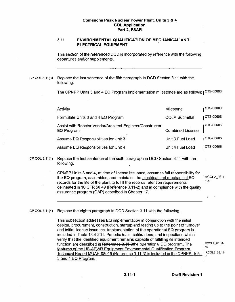
Comanche Peak Nuclear Power Plant, Units 3 & 4COL Application
Part 2, FSAR
ENVIRONMENTAL QUALIFICATION OF MECHANICAL ANDELECTRICAL EQUIPMENT
3.11
This section of the referenced DCD is incorporated by reference with the followingdepartures and/or supplements.
CP, COL 3.11(3) Replace the last sentence of the fifth paragraph in DCD Section 3.11 with thefollowing.
The CPNPP Units 3 and 4 EQ Program implementation milestones are as follows: I CTS-00606
Activity Milestone
Formulate Units 3 and 4 EQ Program
Assist with Reactor Vendor/Architect-Engineer/ConstructorEQ Program
Assume EQ Responsibilities for Unit 3
Assume EQ Responsibilities for Unit 4
COLA Submittal
Combined License
Unit 3 Fuel Load
Unit 4 Fuel Load
I CTS-00606
I CTS-00606
CTS-00606
I CTS-00606
I CTS-00606
CP COL 3.11(1) Replace the first sentence of the sixth paragraph in DCD' Section 3.11" with thefollowing.
CPNPP Units 3 and 4, at time of license issuance, assumes full responsibility forthe EQ program, assembles, and maintains the electrical and mechanical EQrecords for the life of the plant to fulfill the records retention requirementsdelineated in 10 CFR 50.49 (Reference 3.11-2) and in compliance with the qualityassurance program (QAP) described in Chapter 17.
Replace the eighth paragraph in DCD Section 3.11 with the following.
This subsection addresses EQ implementation in conjunction with the initialdesign, procurement, construction, startup and testing up to the point of turnoverand initial license issuance. Implementation of the operational EQ program isincluded in Table 13.4-201. Periodic tests, calibrations, and inspections whichverify that the identified equipment remains capable of fulfilling its intendedfunction are described in Rcfcrccc 3.11 3the operational EQ program. Thefeatures of the US-APWR Equipment Environmental Qualification ProgramTechnical Report MUAP-08015 (Reference 3.11-3) is included in the CPNPP Units3 and 4 EQ Program.
I RCOL2_03.11-4
CP COL 3.11(4)
RCOL2_03.11-15
RCOL2_03.11-5
3.11-1 .11 rft Roicmivn 1
Comanche Peak Nuclear Power Plant, Units 3 & 4COL Application
Part 2, FSAR
CP COL 3.11(5)
3.11.1.1 Equipment Identification
Replace the last sentence of the first paragraph in DCD Subsection 3.11.1.1 withthe following.
Table 3D-201 identifies CPNPP Units 3 and 4 site-specific electrical andmechanical equipment locations and environmental conditions (both normal andaccident) to be addressed in the EQ program. This table lists information onsite-specific safety-related efand important to safety equipment. The provision in RCOL2_03.11-
16the US-APWR DCD for environmental qualification (EQ) of mechanical equipment RCOL2_03.11-will be applied to the plant-specific systems. 3
3.11.1.2 Definition of Environmental Conditions
Replace the fourth sentence of the first paragraph in DCD Subsection 3.11.1.2with the following.
CP COL 3.11(9)
Plant Specific EQ parameters are documented in the corresponding equipment RC(specifications, drawings, procedures, instructions, and qualification packages.Aýy- 1-6
pa• am m icrs e .cuF on ba ec .site u ',c uu urisi ure.ic . uu .". r i ; ;c... :.i i;.thecnVieRonmcntal qualifieatieR documonetation dcccribcd in ScctiOn 3.11.
3.11.3 Qualification Test Results
CP COL 3.11(2) Replace the fifth paragraph in DCD Subsection 3.11.3 with the following.
Test results for se- speeifie -electrical and mechanical equipment are maintained RCOL2_03.1
with the project records as auditable files. Such records are maintained from the 113
time of initial receipt through the entire period during which the subject equipmentremains installed in the plant, is stored for future use, or is held for permitverification. The COL applicant has a responsibility to maintain the project records I RCOL2_03.1
until issuance of the COL. The license holder for CPNPP Units 3 and4 assumes 1-13
full responsibility for the EQ program at time of license issuance. The EQ recordsare maintained for the life of plant to fulfill the records retention requirementsdelineated in 10 CFR 50.49 (Reference 3.11-2) and in compliance with the QAPdescribed in Chapter 17.
3.11-2 3.11-2 r-af Ro':fision 4
Comanche Peak Nuclear Power Plant, Units 3 & 4COL Application
Part 2, FSAR
3.11.4 Loss of Ventilation
Replace the second paragraph in DCD Subsection 3.11.4 with the following.
Site-specific electrical and mechanical equipment (including instrumentation andcontrol and certain accident monitoring equipment), subject to environmentalstress associated with loss of ventilation or other environmental control systemsincluding heat tracing, heating, and air conditioning, is qualified using anequivalent qualification process to that delineated for the US-APWR standardplant as described in Technical Report MUAP-08015 (Reference 3.11-3).
CP COL 3.11(6)
I RCOL2_03.11-8
3.11.5 Estimated Chemical and Radiation Environment
Replace paragraph in DCD, Subsection 3.11.5 with the following.CP COL 3.11(7)
Chemical and radiation environmental requirements for site-specific electrical andmechanical equipment (including instrumentation and control and certain accidentmonitoring equipment) are to be included in the Equipment EQ Technical Report(Reference 3.11-3). This equipment is qualified using an equivalent qualificationprocess to that delineated for the US-APWR standard plant as described inTechnical Report MUAP-08015 (Reference 3.11-3).
CTS-00639RCOL2_03.11-8
3.11.6 Qualification of Mechanical Equipment
CPCOL 3.11(8) Replace the second paragraph in DCD, Subsection 3.11.6 with the following.
Site-specific mechanical equipment requirements are to be included in Table3D-201 by completion of detailed design. This equipment is qualified using anequivalent qualification process to that delineated for the US-APWR standardplant as described in Technical Report MUAP-08015 (Reference 3.11-3). RCOL2 03.1
1-8
3.11.7 Combined License Information
CP COL 3.11(1) Replace the content of DCD Subsection 3.11.7 with the following.
3.11(1) Environmental qualification document assembly and maintenance
This COL item is addressed in Section 3.11.
CP COL 3.11(2) 3.11(2) Qualification tests results recorded
3.11-3 3.1-3 r-aft RPAF*cion I

U. S. Nuclear Regulatory CommissionCP-200901560TXNB-0906411/11/2009
Attachment 9
Response to Request for Additional Information No. 3729 (CP RAI #93)
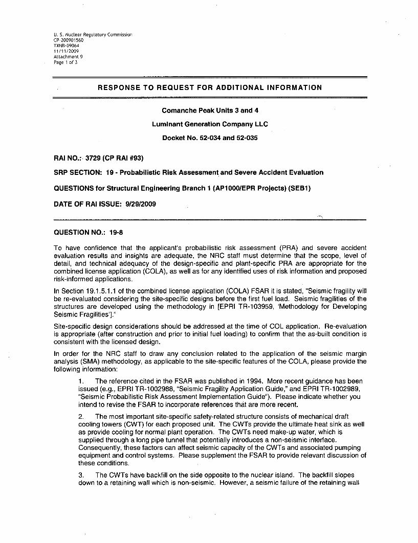
U. S. Nuclear Regulatory CommissionCP-200901 560TXNB-0906411/11/2009Attachment 9Page 1 of 3
RESPONSE TO REQUEST FOR ADDITIONAL INFORMATION
Comanche Peak Units 3 and 4
Luminant Generation Company LLC
Docket No. 52-034 and 52-035
RAI NO.: 3729 (CP RAI #93)
SRP SECTION: 19 - Probabilistic Risk Assessment and Severe Accident Evaluation
QUESTIONS for Structural Engineering Branch 1 (AP1000/EPR Projects) (SEB1)
DATE OF RAI ISSUE: 9/29/2009
QUESTION NO.: 19-8
To have confidence that the applicant's probabilistic risk assessment (PRA) and severe accidentevaluation results and insights are adequate, the NRC staff must determine that the scope, level ofdetail, and technical adequacy of the design-specific and plant-specific PRA are appropriate for thecombined license application (COLA), as well as for any identified uses of risk information and proposedrisk-informed applications.
In Section 19.1.5.1.1 of the combined license application (COLA) FSAR it is stated, "Seismic fragility willbe re-evaluated considering the site-specific designs before the first fuel load. Seismic fragilities of thestructures are developed using the methodology in [EPRI TR-103959, 'Methodology for DevelopingSeismic Fragilities']."
Site-specific design considerations should be addressed at the time of COL application. Re-evaluationis appropriate (after construction and prior to initial fuel loading) to confirm that the as-built condition isconsistent with the licensed design.
In order for the NRC staff to draw any conclusion related to the application of the seismic marginanalysis (SMA) methodology, as applicable to the site-specific features of the COLA, please provide thefollowing information:
1. The reference cited in the FSAR was published in 1994. More recent guidance has beenissued (e.g., EPRI TR-1002988, "Seismic Fragility Application Guide," and EPRI TR-1002989,"Seismic Probabilistic Risk Assessment Implementation Guide"). Please indicate whether youintend to revise the FSAR to incorporate references that are more recent.
2. The most important site-specific safety-related structure consists of mechanical draftcooling towers (CWT) for each proposed unit. The CWTs provide the ultimate heat sink as wellas provide cooling for normal plant operation. The CWTs need make-up water, which issupplied through a long pipe tunnel that potentially introduces a non-seismic interface.Consequently, these factors can affect seismic capacity of the CWTs and associated pumpingequipment and control systems. Please supplement the FSAR to provide relevant discussion ofthese conditions.
3. The CWTs have backfill on the side opposite to the nuclear island. The backfill slopesdown to a retaining wall which is non-seismic. However, a seismic failure of the retaining wall
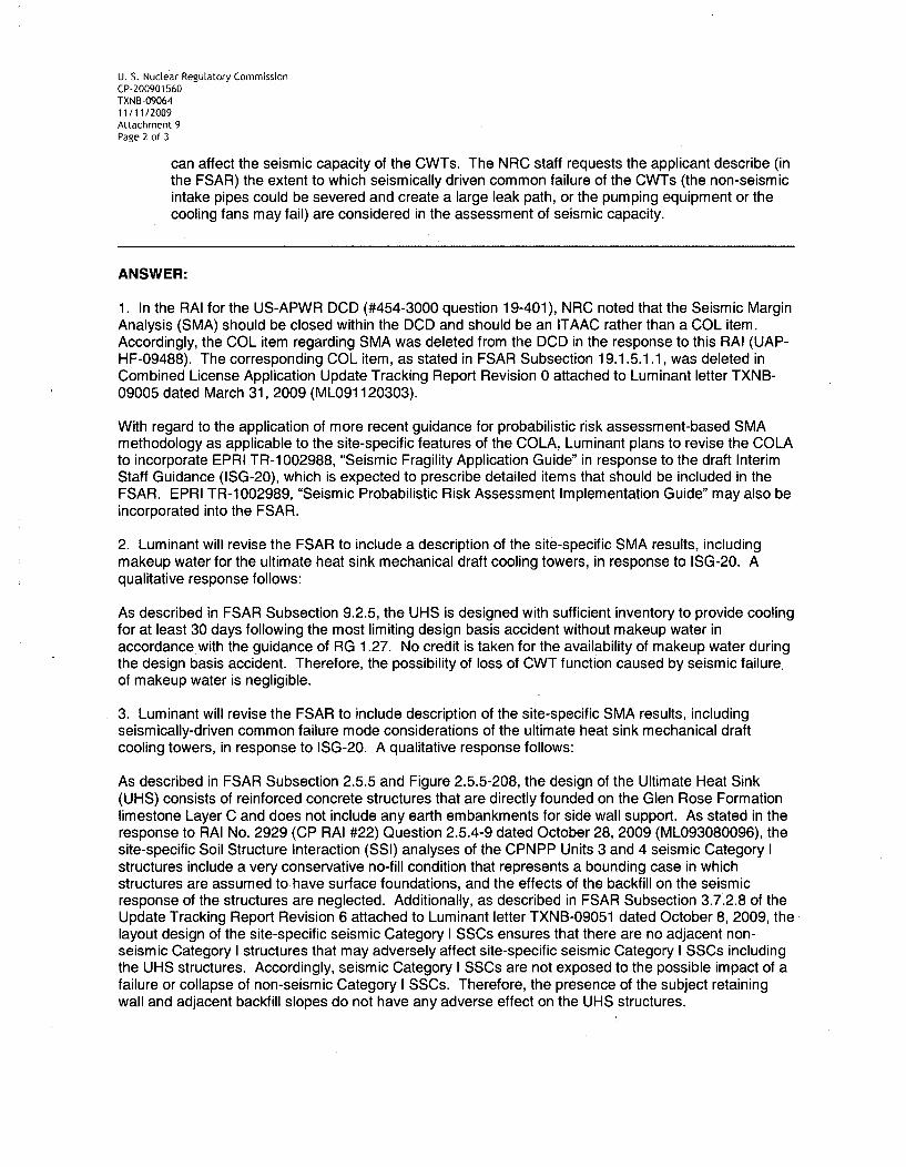
U. S. Nuclear Regulatory CommissionCP-200901560TXNB-0906411/11/2009Attachment 9Page 2 of 3
can affect the seismic capacity of the CWTs. The NRC staff requests the applicant describe (inthe FSAR) the extent to which seismically driven common failure of the CWTs (the non-seismicintake pipes could be severed and create a large leak path, or the pumping equipment or thecooling fans may fail) are considered in the assessment of seismic capacity.
ANSWER:
1. In the RAI for the US-APWR DCD (#454-3000 question 19-401), NRC noted that the Seismic MarginAnalysis (SMA) should be closed within the DCD and should be an ITAAC rather than a COL item.Accordingly, the COL item regarding SMA was deleted from the DCD in the response to this RAI (UAP-HF-09488). The corresponding COL item, as stated in FSAR Subsection 19.1.5.1.1, was deleted inCombined License Application Update Tracking Report Revision 0 attached to Luminant letter TXNB-09005 dated March 31, 2009 (ML091120303).
With regard to the application of more recent guidance for probabilistic risk assessment-based SMAmethodology as applicable to the site-specific features of the COLA, Luminant plans to revise the COLAto incorporate EPRI TR-1002988, "Seismic Fragility Application Guide" in response to the draft InterimStaff Guidance (ISG-20), which is expected to prescribe detailed items that should be included in theFSAR. EPRI TR-1002989, "Seismic Probabilistic Risk Assessment Implementation Guide" may also beincorporated into the FSAR.
2. Luminant will revise the FSAR to include a description of the site-specific SMA results, includingmakeup water for the ultimate heat sink mechanical draft cooling towers, in response to ISG-20. Aqualitative response follows:
As described in FSAR Subsection 9.2.5, the UHS is designed with sufficient inventory to provide coolingfor at least 30 days following the most limiting design basis accident without makeup water inaccordance with the guidance of RG 1.27. No credit is taken for the availability of makeup water duringthe design basis accident. Therefore, the possibility of loss of CWT function caused by seismic failure.of makeup water is negligible.
3. Luminant will revise the FSAR to include description of the site-specific SMA results, includingseismically-driven common failure mode considerations of the ultimate heat sink mechanical draftcooling towers, in response to ISG-20. A qualitative response follows:
As described in FSAR Subsection 2.5.5 and Figure 2.5.5-208, the design of the Ultimate Heat Sink(UHS) consists of reinforced concrete structures that are directly founded on the Glen Rose Formationlimestone Layer C and does not include any earth embankments for side wall support. As stated in theresponse to RAI No. 2929 (CP RAI #22) Question 2.5.4-9 dated October 28, 2009 (ML093080096), thesite-specific Soil Structure Interaction (SSI) analyses of the CPNPP Units 3 and 4 seismic Category Istructures include a very conservative no-fill condition that represents a bounding case in whichstructures are assumed to have surface foundations, and the effects of the backfill on the seismicresponse of the structures are neglected. Additionally, as described in FSAR Subsection 3.7.2.8 of theUpdate Tracking Report Revision 6 attached to Luminant letter TXNB-09051 dated October 8, 2009, thelayout design of the site-specific seismic Category I SSCs ensures that there are no adjacent non-seismic Category I structures that may adversely affect site-specific seismic Category I SSCs includingthe UHS structures. Accordingly, seismic Category I SSCs are not exposed to the possible impact of afailure or collapse of non-seismic Category I SSCs. Therefore, the presence of the subject retainingwall and adjacent backfill slopes do not have any adverse effect on the UHS structures.
U. S. Nuclear Regulatory CommissionCP-200901560TXNB-0906411/11/2009Attachment 9Page 3 of 3
The intake (makeup) piping layout precludes draining of cooling tower basin water from the failed non-seismic intake piping. The elevation of pumping equipment and the cooling fans are higher than theelevation of the wall top (826 feet) and the ground elevation level (822 feet), and are enclosed by theconcrete wall as is shown in Figure 3.8-208 and 3.8-209, the pumping equipment and the cooling fansare protected from flooding effect due to the failure of the non-seismic intake piping in UHS.
Therefore, it can be concluded that seismically driven common failures are not significant in the CPNPP
Units 3 and 4 SMA.
Impact on R-COLA
None.
Impact on S-COLA
None.
Impact on DCD
None.
U. S. Nuclear Regulatory CommissionCP-200901 560TXNB-0906411/11/2009
Attachment 10
Response to Request for Additional Information No. 3790 (CP RAI # 98)
The following FSAR pages are assembled at the end of this attachment:
14.2-7
14.2-8

U. S. NucLear Regulatory CommissionCP-200901560TXNB-0906411/11/2009Attachment 10Page 1 of 6
RESPONSE TO REQUEST FOR ADDITIONAL INFORMATION
Comanche Peak Units 3 and 4
Luminant Generation Company LLC
Docket No. 52-034 and 52-035
RAI NO.: 3790 (CP RAI #98)
SRP SECTION: 14.02 - Initial Plant Test Program - Design Certification and New LicenseApplicants
QUESTIONS for Quality and Vendor Branch 1 (AP1000/EPR Projects) (CQVP)
DATE OF RAI ISSUE: 9/30/2009
QUESTION NO.: 14.02-15
Applicants for standard plant design approval must provide plans for preoperational testing andinitial operations in accordance with 10 CFR 50.34(b)(6)(iii) requirements. The US-APWR Designcontrol document (DCD) Tier 2, Section 14.2.12.1.34, "Essential Service Water SystemPreoperational Test," describes the initial test program for the essential service water system(ESWS). The results of the ESWS test programs are considered to be acceptable if the ESWSperforms as described in Tier 2 of the DCD Section 9.2.1, "Essential Service Water System."
US-APWR DCD COL item 14.2(10) states that the applicant is responsible for testing outside thescope of the certified design in accordance with the criteria in DCD Section 14.2.1, "Summary ofTest Program and Objectives." As a result, the combined license (COL) applicant has added apreoperational test that addresses ESW system components. In Tier 2, COL FSAR Section14.2.12.113, "Ultimate Heat Sink Preoperational Test," added by the COL applicant, the ESWSpumps are tested, including at basin minimum water levels, to verify that the ESW pumps providedesign flow rates.
The COL application does not include a preoperational test of the ESWS blowdown system, as theUS-APWR DCD, COL Item 9.2(7) was revised in August 2008'to include this test.
Another item that was not addressed by the COL (COL Item 9.5(2)) was testing of the ESWS to thefire protection service system (FSS) at the combined required flow rates of 567 liters per minute(150 gpm).
The applicant is requested to provide the following information:
* Provide a description in Section 14.2 of the COL FSAR for testing of the ESWS blowdownsystem.

U. S. Nuclear Regulatory CommissionCP-200901560,TXNB-0906411/11/2009Attachment 10Page 2 of 6
0 Provide a description in Section 14.2 of the COL FSAR of testing of the ESWS valves to theFSS at the required flow rates, including the hose stations located in the RB and ESWS pumphouse. Testing should include verification that the ESWS can still perform its intended function(flow rates and pressure) with the fire lines in service.
ANSWER:
FSAR Subsection 14.2.12.1.113 has been revised to include testing the ESWS valves to the FSS at therequired flow rates to the hose stations located in the RB and ESWS pump house. Testing will includeverification that the ESWS can still maintain required flow rates and pressure with the fire lines inservice.
As described in Subsection 9.2.5.2.2, "a portion of the basin water is discharged through the blowdownvia the ESWS when the makeup water is available. The blowdown rate is determined using aconductivity cell located at the ESW pump discharge and is based on the total dissolved solids in thewater and the makeup water source." Performance testing of this feature is included in the FSARSubsection 14.2.12.1.113 Item C.3 as part of the chemistry control mode. Item C.3 has been clarified tospecifically identify the ESWS blowdown features.
Impact on R-COLA
See attached marked-up FSAR Draft Revision 1 pages 14.2-7 and 14.2-8 at the end of this attachment.
Impact on S-COLA
None.
Impact on DCD
None
U. S. Nuclear Regulatory CommissionCP-200901560TXNB-0906411/11/2009Attachment 10Page 3 of 6
RESPONSE TO REQUEST FOR ADDITIONAL INFORMATION
Comanche Peak Units 3 and 4
Luminant Generation Company LLC
Docket No. 52-034 and 52-035
RAI NO.: 3790 (CP RAI #98)
SRP SECTION: 14.02 - Initial Plant Test Program - Design Certification and New LicenseApplicants
QUESTIONS for Quality and Vendor Branch 1 (AP1 OOO/EPR Projects) (CQVP)
DATE OF RAI ISSUE: 9/30/2009
QUESTION NO.: 14.02-16
Since the ultimate heat sink (UHS) for the US-APWR is a site-specific system, COL applicants need toestablish the applicable initial test program requirements. This is specified by COL Information Item14.2(10), which requires COL applicants to establish test abstracts for site-specific systems. Theapplicant addressed this COL information item for Comanche Peak (in part) by providing FSAR TestAbstract 14.2.12.113, "Ultimate Heat Sink (UHS) System Preoperational Test." Based on a review ofthis test abstract, the staff found that the following items need to be addressed and the test abstractneeds to be revised as appropriate to reflect this information:
" Objective 3 is to demonstrate the operation of the UHS transfer pumps and interlocks.However, FSAR Section 9.2.5 does not describe any interlocks for the UHS transfer pumps.Also, like the ESWS pumps, the UHS transfer pumps need to be tested at the minimum (30day) water level to demonstrate that design flow rate can be maintained.
* Objective 4 is to demonstrate (in part) operation of controls and interlocks. It is not clear whatcontrols and interlocks are being referred to and they need to be better described.
" Item C.1 refers to UHS transfer pump interlocks, but none are described in FSAR Section9.2.5. Likewise for Item D.1.
* Item C.2 specifies performance testing of the ESWS pumps and similar testing of the UHStransfer pumps is needed, including demonstration of adequate performance with decreasinglevel. Likewise for the acceptance criteria specified in D.1.
ANSWER:
There are no interlocks associated with the UHS transfer pumps and Objective 3 has been clarified toreflect this. A test to demonstrate that the UHS transfer pumps maintain the design flow rates at theminimum water level at the end of the 30-day emergency period has been added in A.2.
U. S. Nuclear Regulatory CommissionCP-200901560TXNB-0906411/11/2009Attachment 10Page 4 of 6
FSAR Subsection 9.2.5.2.2 discusses the automatic opening and closing of the makeup control valvesat low UHS basin water level signals. FSAR Subsection 9.2.5.5 discusses the operation of theblowdown control valves. A low UHS basin water level signal or emergency core cooling systemactuation signal causes the valves to automatically close to preserve the ESWS cooling function duringthese conditions. Performance testing of basin water level logic has been specified in item A.4.
As stated above, there are no UHS transfer pump interlocks, and the phrase mentioning the UHStransfer pump interlocks in C.1 and D.2 has been deleted.
Performance testing of the UHS transfer pumps has been added as specified in item C.2 and in theacceptance criteria described in D.1.
Impact on R-COLA
See attached marked-up FSAR Draft Revision 1 pages 14.2-7 and 14.2-8 at the end of this attachment.
Impact on S-COLA
None.
Impact on DCD
None.

Comanche Peak Nuclear Power Plant, Units 3 & 4COL Application
Part 2, FSAR
14.2.12.1.113 Ultimate Heat Sink (UHS) System Preoperational Test
A. Objectives
1. To demonstrate operation of the UHS cooling towers andassociated fans, essential service water (ESW) pumps, and UHStransfer pumps.
2. With the basin at minimum level (end of the 30 day emergency period),to demonstrate that the ESW pumps and the UHS transfer pumpsmaintain design flow rates.
3. To demonstrate the operation of the UHS transfer pumps-andasseofiatcd interlocks.
4. To demonstrate the operation of the UHS basin water level sensorsand basin water level controls, and water chemistry monitors,controls, basin water level logiciR4eFkcee4s, and associatedblowdown equipment.
B. Prerequisites
1. Required construction testing is completed.
2. Component testing and instrument calibration is completed.
3. Test instrumentation is available and calibrated.
4. Required support systems are available.
5. Required system flushing/cleaning is completed.
6. Required electrical power supplies and control circuits areenergized and operational.
7. Makeup water to the UHS basins is available.
C. Test Method
1. System component control and interlock circuits and alarms areverified, including cooling tower fan logic, basin water levelsensors, makeup water control, basin process chemical sensors,blowdown control valves, and U.HS tran.f.. pump intrlcc... .
2. The performance of each ESW pump isand UHS transfer pump aremonitored as basin water level is decreased to the minimum waterlevel (end of the 30 day emergency period).
3. Basin water level and chemistry controls are monitored duringcontinuous operations in the water level and chemistry controlmode using the ESWS blowdown feature.
I RCOL2_14.02-16
RCOL2 14.02-16
I RCOL2_14.02-16
RCOL2_14.02-16
RCOL2 14.02-15
14.2-7 14.2-7 Draft Reymseein 1
Comanche Peak Nuclear Power Plant, Units 3 & 4COL Application
Part 2, FSAR
4. The capability of the ESWS to provide water to the FSS isdemonstrated by opening the isolation valves and obtaining a totalflow of at least 150 gpm to the hose stations located in the R/B andESWS pump house while maintaining required ESWS flows andpressures.
RCOL2 14.02-15
D. Acceptance Criteria
1. With the basin at minimum level (end of the 30 day emergencyperiod), each ESW pump and UHS transfer pump maintains designflow rates.
2. UHS transfer pumps and assa iatcd intcrlockc operate asdiscussed in Subsection 9.2.5.
3. UHS basin water level sensors and basin water level controls, andwater chemistry monitors, controls, interlocks and associatedblowdown equipment operate as discussed in Subsection 9.2.5.
4. ESWS maintains required flows and pressures while water isprovided to the FSS as described in Subsection 9.2.1.3.
I RCOL2_14.02-16
I RCOL2_14.02-16
RCOL2_14.02-15
CP COL 14.2(10) 14.2.12.1.114 UHS ESW Pump House Ventilation System PreoperationalTest
A. Objectives
1. To demonstrate operation of the UHS ESW pump house ventilationsystem.
B. Prerequisites
1. Required construction testing is completed.
2. Component testing and instrument calibration are completed.
3. Test instrumentation is available and calibrated.
4. Required support systems are available.
C. Test Method
1. Simulate interlock signals for each exhaust fan and unit heater and CTS-00818
verify operation and annunciation.
2. Verify that alarms and status indications are functional.
3. Verify design airflow.
14.2-8 Draft R..:iooRn .
U. S. Nuclear ReguLatory CommissionCP-200901560TXNB-0906411/11/2009
Attachment 11
Response to Request for Additional Information No. 3834 (CP RAI #120
U. S. Nuclear Regulatory CommissionCP-200901560TXNB-0906411/11/2009Attachment 11Page 1 of 1
RESPONSE TO REQUEST FOR ADDITIONAL INFORMATION
Comanche Peak Units 3 and 4
Luminant Generation Company LLC
Docket No. 52-034 and 52-035
RAI NO.: 3834 (CP RAI #120)
SRP SECTION: 16 - Technical Specifications
QUESTIONS for Technical Specification Branch (CTSB)
DATE OF RAI ISSUE: 10/5/2009
QUESTION NO.: 16-17
By letter dated September 29, 2009, the NRC staff sent RAI letter No 91 (3315) to Luminant. In question 16-16 (13138) of RAI No. 91, the NRC staff discussed Interim Staff Guidance (ISG) Document DC/COL-ISG-8,'Necessary Content of Plant-Specific Technical Specifications When a Combined License is Issued,' datedDecember 9, 2008. This ISG stated that combined license applicants (COLA) could resolve all generictechnical specification COL action items before COL issuance by using one of three options. In the NRCstaff's discussion of Option 3 to the ISG, the NRC staff requested that for an applicant selectin' Option 3,the applicant model the Setpoint Control program (SCP) Specification, based on the SCP Specificationdeveloped in the ESBWR DC review, with suitable terminology changes to conform to the Comanche Peak,Units 3 and 4 setpoint methodology.
The NRC staff had included an example of a setpoint control program specification as part of question 16-16;however, this example was inadvertently omitted from the NRC staff's letter to Luminant. The setpoint controlprogram specification is shown below and is provided to Luminant as an example when providing a responseto RAI Number 91.
ANSWER:
See the response to RAI No. 3315 (CP RAI #91) Question 16-16 in Attachment 2 to this letter.
Impact on R-COLA
None.
Impact on S-COLA
None.
Impact on DCD
None.