Embed Size (px)
DESCRIPTION
name: lubricants-02-00162.pdf
Citation preview
Lubricants 2014, 2, 162-176; doi:10.3390/lubricants2040162
lubricants ISSN 2075-4442
www.mdpi.com/journal/lubricants
Article
Windage Power Losses of Ordinary Gears: Different CFD Approaches Aimed to the Reduction of the Computational Effort
Franco Concli 1,*, Carlo Gorla 1, Augusto Della Torre 2 and Gianluca Montenegro 2
1 Department of Mechanical Engineering, Politecnico di Milano, Via La Masa 1, I-20156 Milano,
Italy; E-Mail: [email protected] 2 Department of Energy, Politecnico di Milano, Via Lambruschini 4, I-20156 Milano, Italy;
E-Mails: [email protected] (A.D.T.); [email protected] (G.M.)
* Author to whom correspondence should be addressed; E-Mail: [email protected];
Tel.: +39-02-2399-8223; Fax: +39-02-2399-8202.
External Editor: David Mba
Received: 21 July 2014; in revised form: 18 August 2014 / Accepted: 29 August 2014 /
Published: 15 October 2014
Abstract: Efficiency improvement is one of the main challenges in all fields of design. The
reduction of power losses is becoming a great concern also in the design of power
transmissions. For this reason it is important to have specific models available in order to
quantify the power losses during the design stage. The power losses of a gear transmission
can be subdivided into bearing losses, seal losses, meshing losses and hydraulic losses.
Although literature provides models for the prediction of losses related to bearings or to gear
meshing, for the calculations of the losses generated by the interaction with the lubricant,
only few and simplified models are available. For this reason the authors recognize that a
general purpose method is required in order to overcome this lack of fit and to improve the
capability to predict the efficiency of gearboxes. Being able to compare different design
solutions means being able to improve the efficiency, reduce the operating temperature and,
consequently, improve the reliability of the system. In this paper, the windage losses generated
by a single rotating gear have been studied exploiting different numerical approaches. The
results obtained have been compared with measurements showing good agreement.
Keywords: gear; efficiency; windage losses; CFD; MRF; lubricant
OPEN ACCESS
Lubricants 2014, 2 163
1. Introduction
Efficiency has become a great concern during the design of power transmissions for several fields of
application. Increasing the efficiency of power transmissions can bring a significant contribution to
reduce pollutant emissions and save energy. Moreover, the reduction of power losses, which are
dissipated in the form of heat, can improve reliability, which is related to different thermal regimes, and
allow the application of downsizing, weight reduction and system architecture. The first step towards
the improvement of efficiency is to have appropriate models to compare different design solutions,
during the design stage. Although power transmissions are typically a part of complex systems, in which
other parts like internal combustion engines have much larger power losses, improvements in the efficiency
of power transmissions can make considerable savings on a global scale. Power losses in gear transmissions
come from several sources: gears, bearings, seals and other transmission components like clutches or
synchronizers [1]. Losses related to gear meshing have been deeply investigated and reliable models for
the prediction are already available in the literature [1]. On the contrary, other losses determined by the
interaction with lubricant, such as oil churning, oil squeezing and windage, still need to be studied and
properly modeled [2]. These losses, in fact, depending on the gearbox configuration and operating
conditions, can amount to approximately 40%–60% of the total losses [3]. Moreover, for these losses,
discrete margins of improvement are still possible, while for other sources, for instance frictional losses,
thanks to the results of many years of studies, the remaining possibilities of improvement are
comparatively lower. Works on hydraulic losses were presented by Dawson [4] and by Marchesse [5]
who focused on the modeling of windage losses whereas Mauz [6], LePrince et al. [7] and
Seetharaman [8] have concentrated on the modeling of churning power losses. All these models have
the main advantage of requiring short computational times; however, they are applicable just under a
restricted range of operating conditions and geometrical configurations, as shown by Eastwick [2].
Furthermore, these models often neglect some important influencing parameters like, for instance, helix
angle and tip diameter. A CFD (computational fluid dynamic) based method was adopted by the authors
in previous papers in order to study the churning and squeezing power losses in planetary
gearboxes [9–11] and the windage losses of ordinary gears [12]. The adopted method was based on
dynamic meshing. This technique allows accurate simulation of the whole transient start-up, but has the
main drawback of requiring long computational times. This study will focus on the evaluation of the
influence of some operating and geometrical parameters on the windage losses generated by a single
rotating gear with 100% dip lubrication. Two approaches have been adopted for this study, each showing
advantages and drawbacks: the multi-reference frame (MRF) and the sliding mesh. The aim of this study
is to verify the accuracy and the reliability of the two approaches for this kind of investigations and to
provide results that can be used effectively in the design practice. For this purpose the open source CFD
tool OpenFOAM® was used [16]. The choice of an open source code has been made because it allows
more flexibility with respect to any close source commercial software, making it possible to customize
the code with the implementation of specific models for the analysis of the physical problem of interest.
The results obtained numerically have been validated with measurements.
Lubricants 2014, 2 164
2. Composition of the Power Losses
Power losses ( ) of geared transmissions can be subdivided into load dependent and load
independent losses (subscript ) [1]. = + + + + + (1)
where
represents the gears power losses due to gear meshing
represents the bearings power losses due to sliding
represents the bearings power losses due to lubrication
represents the seals power losses due to relative sliding
represents other generic power losses
represents the load independent power losses of gears due to the interaction with the lubricant.
The load dependent power losses are losses that increase with the transmitted torque, while the load
independent losses remain constant even if the transmitted torque sinks to zero or increases drastically.
For the sake of completeness it should be mentioned that the last losses are not completely independent
of the transmitted torque: an increase of load causes an increase of gear meshing and bearing power
losses, leading to an increase of the operating temperature. This causes a reduction in the density and the
viscosity of the lubricant and, therefore, a change in the load independent power losses. The total power
losses can be further subdivided according to the mechanical components that generate them: it can be
therefore distinguished between gear losses (subscripts ), bearing losses (subscript ), seal losses
(subscript ) and other generic losses (subscript ) like those related to clutches or synchronizers. The
gear losses due to the interaction with the lubricant can be furthermore subdivided into squeezing,
windage and churning power losses. The squeezing power losses are related to the pressure gradient that
occurs when the gap at the mesh position changes its volume during the engagement. The windage power
losses are related to the interaction between a single phase fluid and the gears. They are proportional to
the cube of rotational speed. The magnitude of these losses is strongly dependent on the properties of
the fluid. Churning losses arise in dip-lubricated power transmissions when two phases are present.
These are similar to the windage ones, but involve at least one free surface. All these sources of losses
should be minimized on order to improve the efficiency of the gearbox. To do so, it is important to be
able to estimate the influence of different parameters on these losses. In this paper, the authors propose
two different numerical approaches for this kind of investigations. In particular, a classical dynamic
meshing approach and an MRF approach have been adopted and the results are compared with
experimental measurements. The aim is to assess the capability of the MRF to predict this kind of losses.
The MRF is a simplified approach suitable to describe the regime condition, ensuring large savings of
computational effort compared with the dynamic mesh approach. The two methods are validated with
the measurements, and the influence of the three most sensitive parameters [6] (tip diameter, helix angle
and rotational speed) is then studied.
Lubricants 2014, 2 165
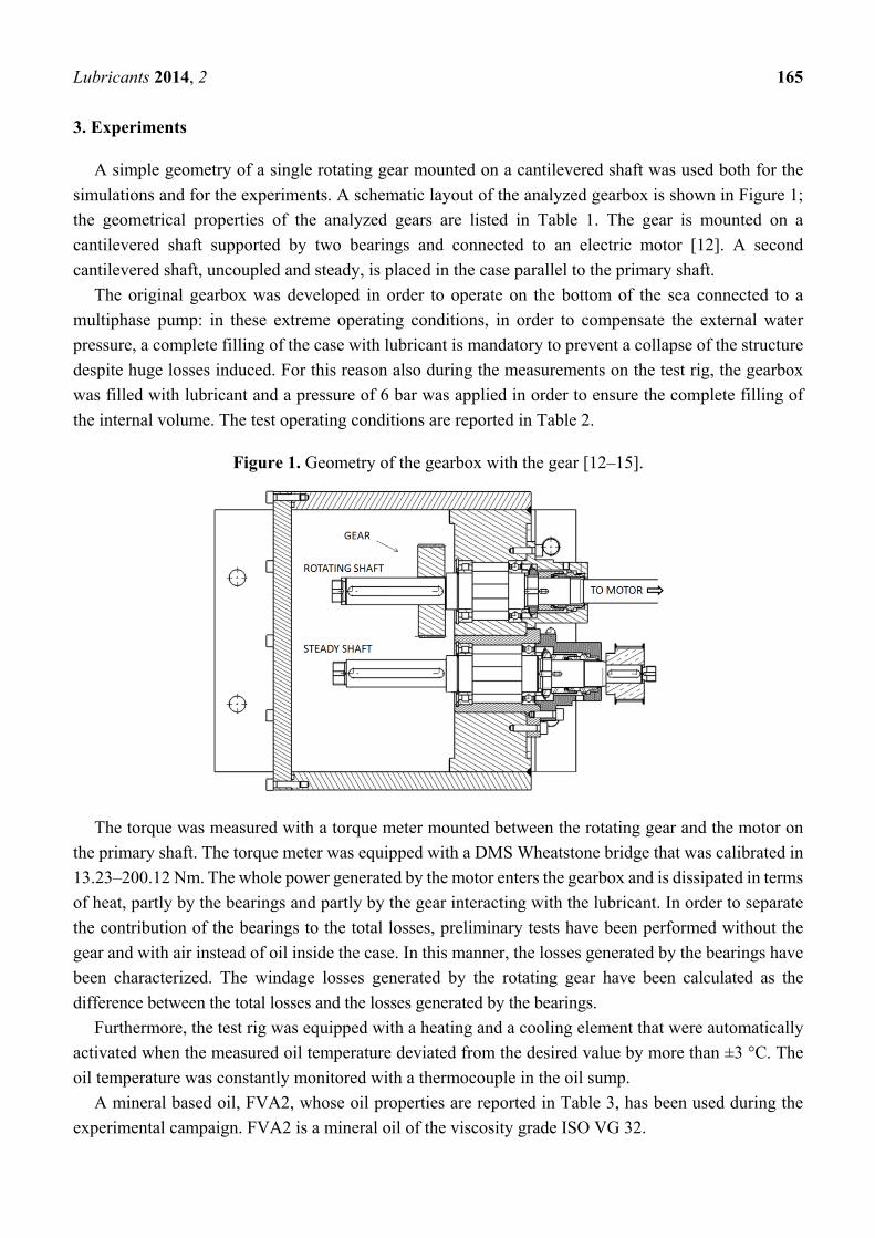
3. Experiments
A simple geometry of a single rotating gear mounted on a cantilevered shaft was used both for the
simulations and for the experiments. A schematic layout of the analyzed gearbox is shown in Figure 1;
the geometrical properties of the analyzed gears are listed in Table 1. The gear is mounted on a
cantilevered shaft supported by two bearings and connected to an electric motor [12]. A second
cantilevered shaft, uncoupled and steady, is placed in the case parallel to the primary shaft.
The original gearbox was developed in order to operate on the bottom of the sea connected to a
multiphase pump: in these extreme operating conditions, in order to compensate the external water
pressure, a complete filling of the case with lubricant is mandatory to prevent a collapse of the structure
despite huge losses induced. For this reason also during the measurements on the test rig, the gearbox
was filled with lubricant and a pressure of 6 bar was applied in order to ensure the complete filling of
the internal volume. The test operating conditions are reported in Table 2.
Figure 1. Geometry of the gearbox with the gear [12–15].
The torque was measured with a torque meter mounted between the rotating gear and the motor on
the primary shaft. The torque meter was equipped with a DMS Wheatstone bridge that was calibrated in
13.23–200.12 Nm. The whole power generated by the motor enters the gearbox and is dissipated in terms
of heat, partly by the bearings and partly by the gear interacting with the lubricant. In order to separate
the contribution of the bearings to the total losses, preliminary tests have been performed without the
gear and with air instead of oil inside the case. In this manner, the losses generated by the bearings have
been characterized. The windage losses generated by the rotating gear have been calculated as the
difference between the total losses and the losses generated by the bearings.
Furthermore, the test rig was equipped with a heating and a cooling element that were automatically
activated when the measured oil temperature deviated from the desired value by more than ±3 °C. The
oil temperature was constantly monitored with a thermocouple in the oil sump.
A mineral based oil, FVA2, whose oil properties are reported in Table 3, has been used during the
experimental campaign. FVA2 is a mineral oil of the viscosity grade ISO VG 32.

Lubricants 2014, 2 166
Table 1. Geometrical properties of the analyzed gears.
Influencing
parameters
Face width
[mm]
Tip diameter
[mm]
Helix
angle β [°]
Pressure angle
[°]
Number of
teeth [-]
Normal module
[mm]
Reference 40 102.5 0 20 23 4
Tip diameter 40 96.5–98 0 20 23 4
Helix angle 40 102.5 20 20 23 4
Table 2. Test operating conditions.
Operating temperature [°C] Operating pressure [bar] Tangential velocity range [m/s]
≈90 6 0–38.3
Table 3. Oil properties of the used lubricants.
Oil Kinetic viscosity at 40 °C
[mm²/s] Kinetic viscosity at 100 °C
[mm²/s] Density at 15 °C
[kg/m³]
FVA2 29.8 5.2 871
4. CFD Simulations
In this work, CFD simulations were run considering a simplified geometry of this test rig
configuration. In particular, the presence of the second shaft, on which no gear is mounted, was neglected
and some other minor geometrical simplifications (e.g., chamfers) were introduced. Preliminary
comparisons with the results obtained with more detailed models [12] were made, confirming the
negligible influence of this approximation on the results. As introduced before, the windage power losses
have been numerically analyzed be means of two different CFD approaches, i.e., sliding mesh and MRF.
4.1. Sliding Mesh Approach
The first approach is based on a sliding mesh technique. The sliding mesh model is theoretically the
most accurate method for simulating rotating flows. It is able to correctly describe the whole transient
start-up but it is also the most computationally demanding. In this technique two or more cell zones are
created separately. Each cell zone is bounded by at least one interface where it meets the opposing cell
zone. The interface of adjacent cell zones is associated with another one to form an arbitrary mesh
interface (AMI). The two cell zones will slide relative to one another along the mesh interface in discrete
steps. The AMI operates by projecting one of the patches boundary mesh onto the other. In other words,
the two sub-domains are geometrically separated but numerically connected by an arbitrary mesh
interface that ensures that the values of a generic field are the same on both sides of the interface. Appling
this technique to the specific case of the rotating gear means creating a first cylindrical sub-domain
(which will rotate) around the gear and a second stationary domain in the rest of the internal volume of
the gearbox. The two domains have been meshed separately (the two meshes should not be necessarily
conformal). Figure 2 shows the two mesh zones and how they move relative to one another.

Lubricants 2014, 2 167
Figure 2. The two different cell zones adopted in order to apply a rigid rotation to the faces
of the gear and how they move relative to one another.
In this approach, one of the meshes has a rigid rotation without deformation, and the other mesh
is steady.
4.2. MRF Approach
The MRF model is a steady state approximation in which individual cell zones move at different
rotational speeds. The flow in each moving cell zone is solved using the moving reference frame
equations in which additional terms related to the Coriolis acceleration (2 × ) and the centripetal
acceleration ( × × ) are added to the momentum conservation equation: ( ) + ∇ ∙ ( ) + (2 × + × × )= −∇p + ∇ ∙ ∇ + ∇ + + (2)
where is the pressure, is the density, is the viscosity, is the gravitational force, represents
external body forces, is the angular velocity relative to a stationary (inertial) reference frame and
is defined as = − × where is the position vector from the origin of the rotating frame. Also
the continuity equation is modified and written in terms of relative velocities: + ∇ ∙ ( ) = 0 (3)
At the interfaces between cell zones, a local reference frame transformation is performed to enable
flow variables in one zone to be used to calculate fluxes at the boundary of the adjacent zone. It should
be noted that the MRF approach does not account for the relative motion of a moving zone with respect
to adjacent zones; the grid remains fixed for the computation. This is analogous to freezing the motion
of the moving part in a specific position and observing the instantaneous flow field with the rotor in that
position. Although the MRF approach is clearly an approximation, it can provide a reasonable model of
the flow for many applications, considerably reducing the computational effort with respect to the sliding
meshes approach. However, the MRF model does not accurately simulate the transient start-up but gives
just a regime solution of an unsteady problem.
In this specific case, the mesh is similar to the mesh adopted for the sliding mesh method (Figure 2)
with the only difference that the two domains (the cylinder around the gear and the rest of the

Lubricants 2014, 2 168
computational domain) are not meshed separately as before but are just two separate cell zones of the
same mesh, resulting therefore in a conformal mesh.
4.3. Discretization
Both sub-domains have been discretized adopting the standard mesh generator provided by
OpenFOAM. The static cell zone has been discretized directly with the blockMesh utility (which
produces a structured mesh), while the dynamic cell zone has been discretized using the snappyHexMesh
utility. This utility starts from a background structured mesh and a Stereolithography (STL) file that
describes the gear geometry: the mesh approximately conforms to the surface by refining the starting
background mesh where the STL surface intersects cell edges, following an octree algorithm. Once the
splitting of feature and surface completes, a process of cell removal begins, resulting in a step mesh
(Figure 3b). The next stage of the meshing process moves cell vertex points onto surface geometry to
remove the jagged castellated surface from the mesh. The process displaces the vertices in the castellated
boundary onto the STL surface, solves for relaxation of the internal mesh with the latest displaced
boundary vertices, finds the vertices that cause mesh quality parameters to be violated and reduces the
displacement of those vertices from their initial value. This procedure is repeated iteratively until mesh
quality is satisfied.
Figure 3. Steps of the meshing process: (a) geometry overlapping the background mesh;
(b) castellated mesh; (c) final mesh.
4.4. Solver Settings
Simulations were run adopting incompressible pressure-velocity coupled solvers based on the
SIMPLE algorithm (Semi-Implicit Method for Pressure Linked Equations). In particular, the standard
steady SIMPLE algorithm [13] was adopted for the simulations based on the MRF approach. On the
other hand, in the case of the sliding mesh approach, which allows the description of transient problems,
the implementation of the transient SIMPLE solver of OpenFOAM (PIMPLE solver, a flexible
implementation of a transient solver that allows operation in both PISO [14] and SIMPLE mode) was
adopted. In both cases the temperature of the lubricant was assumed as uniform in the domain and known
a priori, therefore the energy conservation equation was not considered. In a similar way the density and
the viscosity values were set on the basis of the temperature according to Equations (4) and (5).

Lubricants 2014, 2 169
= 1000 − ( − 15) ∙ 0.0007 ∙ 1000 (4)= 10 ( ( ) ( ))( ) ( ) ∙( ( ) ( )) ( ) ∙ 10 (5)
This, of course, is a simplification that is, in the authors’ opinion, acceptable for this kind of study;
in industrial calculations, the inclusion of the energy equation in the calculation will be suggested.
4.5. Operating Conditions
The influence of different parameters and operating conditions such as tangential velocity, tip
diameter and helix angle have been studied with both numerical approaches. Table 4 summarizes the
combination of parameters adopted for each simulation. For each geometrical configuration, the
rotational speed has been varied in a range between 0 and 8000 rpm, meaning tangential velocities up to
38.3 m/s. The operating lubricant temperature was assumed to be equal to 90 °C. The tip diameter, one
of the most influencing parameters [6] on the losses, has been varied from 96.5 mm to 102.5 mm. The
helix angle has been varied from 0° to 20°.
Table 4. Combination of parameters adopted in the different simulations.
# [mm] [mm] [°] [rpm] [mm] [°C] Oil type
1.1 102.5 40 0 2000 4 90 FVA2 1.2 102.5 40 0 5000 4 90 FVA2 1.3 102.5 40 0 8000 4 90 FVA2 2.1 98 40 0 2000 4 90 FVA2 2.2 98 40 0 5000 4 90 FVA2 2.3 98 40 0 8000 4 90 FVA2 3.1 96.5 40 0 2000 4 90 FVA2 3.2 96.5 40 0 5000 4 90 FVA2 3.3 96.5 40 0 8000 4 90 FVA2 4.1 102.5 40 20 2000 4 90 FVA2 4.2 102.5 40 20 5000 4 90 FVA2 4.3 102.5 40 20 8000 4 90 FVA2
5. Results and Discussion
Figure 4b,c shows the streamlines for the simulations with the helical gear at a rotational speed of
2000 rpm (the colors are proportional to the velocities). It appears that the whole domain is involved in
the lubricant circulation. An ideal fluid particle is radially thrown away from the gear surface due to the
centrifugal force and comes again in contact with the gear from the axial direction. This kind of result
points out the importance of optimizing the internal shape of the case to promote the lubricant circulation
and consequently the dissipation of heat that can be beneficial to the reliability of the gearbox.
Furthermore, knowing how the oil flows inside the gearbox allows engineers to reduce its amount
while ensuring good lubrication at the same time.
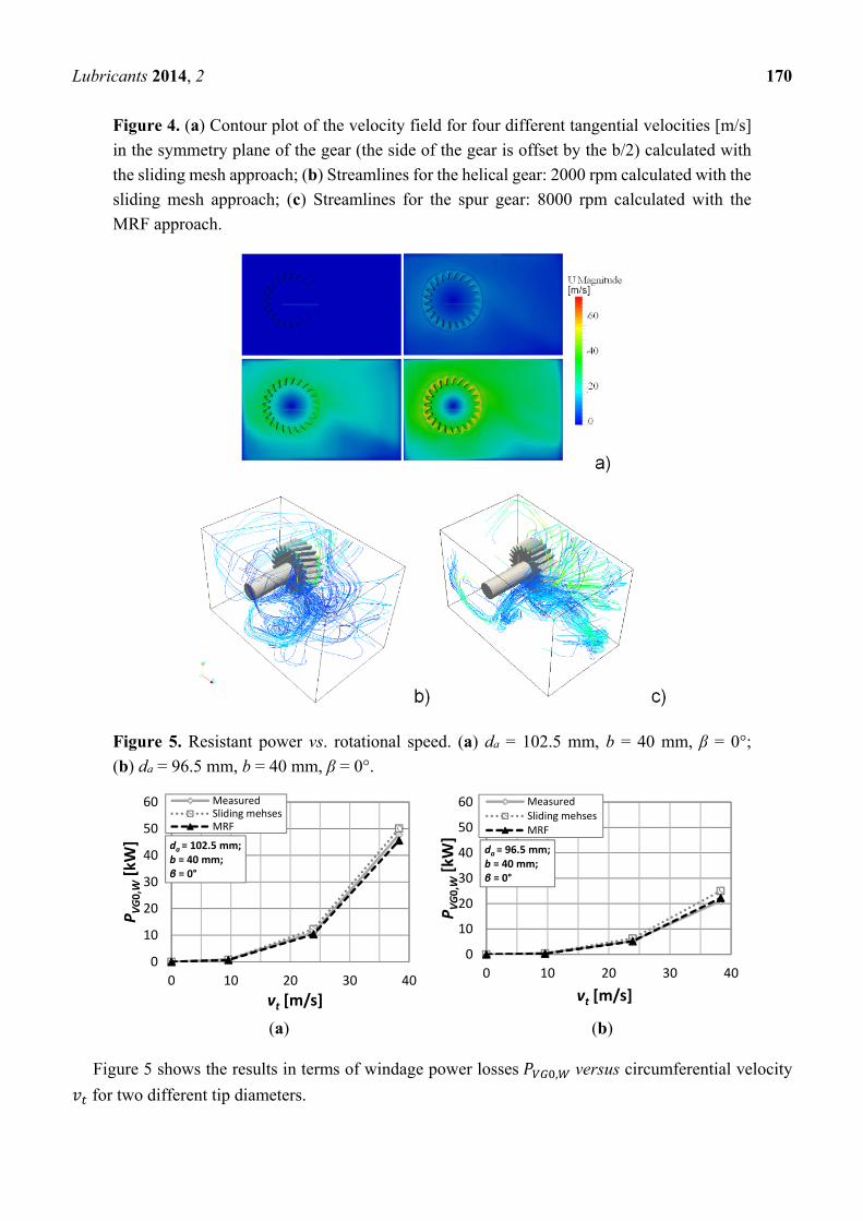
Lubricants 2014, 2 170
Figure 4. (a) Contour plot of the velocity field for four different tangential velocities [m/s]
in the symmetry plane of the gear (the side of the gear is offset by the b/2) calculated with
the sliding mesh approach; (b) Streamlines for the helical gear: 2000 rpm calculated with the
sliding mesh approach; (c) Streamlines for the spur gear: 8000 rpm calculated with the
MRF approach.
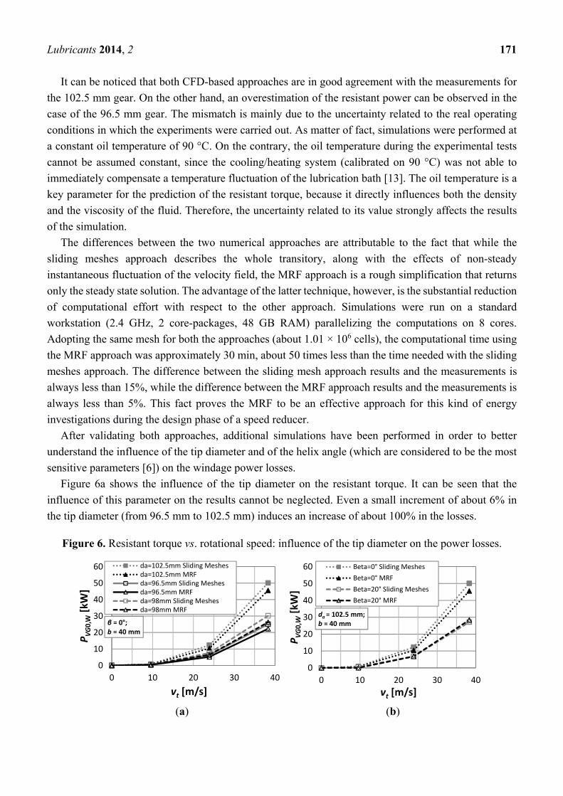
Figure 5. Resistant power vs. rotational speed. (a) da = 102.5 mm, b = 40 mm, β = 0°;
(b) da = 96.5 mm, b = 40 mm, β = 0°.
(a) (b)
Figure 5 shows the results in terms of windage power losses , versus circumferential velocity
for two different tip diameters.
0
10
20
30
40
50
60
0 10 20 30 40
P VG0,
W[k
W]
vt [m/s]
da = 102.5 mm;b = 40 mm;β = 0°
MeasuredSliding mehsesMRF
0
10
20
30
40
50
60
0 10 20 30 40
P VG0,
W[k
W]
vt [m/s]
da = 96.5 mm;b = 40 mm;β = 0°
MeasuredSliding mehsesMRF
Lubricants 2014, 2 171
It can be noticed that both CFD-based approaches are in good agreement with the measurements for
the 102.5 mm gear. On the other hand, an overestimation of the resistant power can be observed in the
case of the 96.5 mm gear. The mismatch is mainly due to the uncertainty related to the real operating
conditions in which the experiments were carried out. As matter of fact, simulations were performed at
a constant oil temperature of 90 °C. On the contrary, the oil temperature during the experimental tests
cannot be assumed constant, since the cooling/heating system (calibrated on 90 °C) was not able to
immediately compensate a temperature fluctuation of the lubrication bath [13]. The oil temperature is a
key parameter for the prediction of the resistant torque, because it directly influences both the density
and the viscosity of the fluid. Therefore, the uncertainty related to its value strongly affects the results
of the simulation.
The differences between the two numerical approaches are attributable to the fact that while the
sliding meshes approach describes the whole transitory, along with the effects of non-steady
instantaneous fluctuation of the velocity field, the MRF approach is a rough simplification that returns
only the steady state solution. The advantage of the latter technique, however, is the substantial reduction
of computational effort with respect to the other approach. Simulations were run on a standard
workstation (2.4 GHz, 2 core-packages, 48 GB RAM) parallelizing the computations on 8 cores.
Adopting the same mesh for both the approaches (about 1.01 × 10⁶ cells), the computational time using
the MRF approach was approximately 30 min, about 50 times less than the time needed with the sliding
meshes approach. The difference between the sliding mesh approach results and the measurements is
always less than 15%, while the difference between the MRF approach results and the measurements is
always less than 5%. This fact proves the MRF to be an effective approach for this kind of energy
investigations during the design phase of a speed reducer.
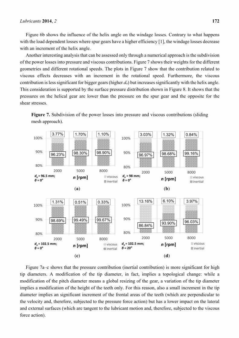
After validating both approaches, additional simulations have been performed in order to better
understand the influence of the tip diameter and of the helix angle (which are considered to be the most
sensitive parameters [6]) on the windage power losses.
Figure 6a shows the influence of the tip diameter on the resistant torque. It can be seen that the
influence of this parameter on the results cannot be neglected. Even a small increment of about 6% in
the tip diameter (from 96.5 mm to 102.5 mm) induces an increase of about 100% in the losses.
Figure 6. Resistant torque vs. rotational speed: influence of the tip diameter on the power losses.
(a) (b)
0
10
20
30
40
50
60
0 10 20 30 40
P VG0,
W[k
W]
vt [m/s]
β = 0°;b = 40 mm
da=102.5mm Sliding Meshesda=102.5mm MRFda=96.5mm Sliding Meshesda=96.5mm MRFda=98mm Sliding Meshesda=98mm MRF
0
10
20
30
40
50
60
0 10 20 30 40
P VG0,
W[k
W]
vt [m/s]
da = 102.5 mm;b = 40 mm
Beta=0° Sliding MeshesBeta=0° MRFBeta=20° Sliding MeshesBeta=20° MRF
Lubricants 2014, 2 172
Figure 6b shows the influence of the helix angle on the windage losses. Contrary to what happens
with the load dependent losses where spur gears have a higher efficiency [1], the windage losses decrease
with an increment of the helix angle.
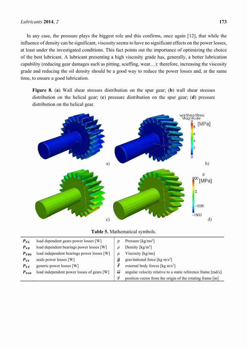
Another interesting analysis that can be assessed only through a numerical approach is the subdivision
of the power losses into pressure and viscous contributions. Figure 7 shows their weights for the different
geometries and different rotational speeds. The plots in Figure 7 show that the contribution related to
viscous effects decreases with an increment in the rotational speed. Furthermore, the viscous
contribution is less significant for bigger gears (higher da) but increases significantly with the helix angle.
This consideration is supported by the surface pressure distribution shown in Figure 8. It shows that the
pressures on the helical gear are lower than the pressure on the spur gear and the opposite for the
shear stresses.
Figure 7. Subdivision of the power losses into pressure and viscous contributions (sliding
mesh approach).
(a) (b)
(c) (d)
Figure 7a–c shows that the pressure contribution (inertial contribution) is more significant for high
tip diameters. A modification of the tip diameter, in fact, implies a topological change: while a
modification of the pitch diameter means a global resizing of the gear, a variation of the tip diameter
implies a modification of the height of the teeth only. For this reason, also a small increment in the tip
diameter implies an significant increment of the frontal areas of the teeth (which are perpendicular to
the velocity and, therefore, subjected to the pressure force action) but has a lower impact on the lateral
and external surfaces (which are tangent to the lubricant motion and, therefore, subjected to the viscous
force action).
96.23% 98.30% 98.90%
3.77% 1.70% 1.10%
80%
90%
100%
2000 5000 8000
n [rpm]da = 96.5 mm;β = 0°
viscousinertial
96.97% 98.68% 99.16%
3.03% 1.32% 0.84%
80%
90%
100%
2000 5000 8000
n [rpm]da = 98 mm;β = 0°
viscousinertial
98.69% 99.49% 99.67%
1.31% 0.51% 0.33%
80%
90%
100%
2000 5000 8000
n [rpm]da = 102.5 mm;β = 0°
viscousinertial
86.84% 93.90% 96.03%
13.16% 6.10% 3.97%
80%
90%
100%
2000 5000 8000
n [rpm]da = 102.5 mm;β = 20°
viscousinertial
Lubricants 2014, 2 173
In any case, the pressure plays the biggest role and this confirms, once again [12], that while the
influence of density can be significant, viscosity seems to have no significant effects on the power losses,
at least under the investigated conditions. This fact points out the importance of optimizing the choice
of the best lubricant. A lubricant presenting a high viscosity grade has, generally, a better lubrication
capability (reducing gear damages such as pitting, scuffing, wear…): therefore, increasing the viscosity
grade and reducing the oil density should be a good way to reduce the power losses and, at the same
time, to ensure a good lubrication.
Figure 8. (a) Wall shear stresses distribution on the spur gear; (b) wall shear stresses
distribution on the helical gear; (c) pressure distribution on the spur gear; (d) pressure
distribution on the helical gear.
Table 5. Mathematical symbols.
load dependent gears power losses [W] Pressure [kg/ms2]
load dependent bearings power losses [W] Density [kg/m3]
load independent bearings power losses [W] Viscosity [kg/ms]
seals power losses [W] gravitational force [kg m/s2]
generic power losses [W] external body forces [kg m/s2]
load independent power losses of gears [W] angular velocity relative to a static reference frame [rad/s]
position vector from the origin of the rotating frame [m]
Lubricants 2014, 2 174
6. Conclusions
In this work CFD has been applied to the investigation of windage power losses of ordinary gears.
Numerical simulations have been performed using two different approaches, namely sliding mesh and
MRF. The aim of this research was both to validate the MRF approach as an effective method for the
prediction of gear transmission power losses and to investigate the influence of the most sensitive
parameters (rotational speed, tip diameter and helix angle) on the windage power losses.
The results have shown that the data obtained with the simplified MRF approach—even though it
only represents the regime condition—are comparable with the measurements and are less
computationally expensive that the sliding mesh approach. On the contrary, the sliding mesh approach
has the advantage of well describing also the initial transient phase.
The winning in terms of computational time for this kind of simulations is in the order of magnitude
of 1:50.
Regarding the obtained results, the tip diameter seems to have, as expected, a huge influence on the
power losses. An increment of this parameter of about 6% increases the losses by about 100%. An
increment in the helix angle, instead, induces a reduction of the power losses, which partially compensate
the increment of the power losses due to gear meshing that arise with helical gears in comparison to spur
gears [1].
The numerical simulations have also provided results regarding the subdivision of the power losses
into viscous and inertial ones. The inertial losses are of a different order of magnitude with respect to
the viscous ones. The percentage contribution of the viscous effects decreases with an increment in the
rotational speed, with an increment in the tip diameter of the gear and decrease with an increase in the
helix angle. These results suggest the use of high viscosity oil with low density in order to ensure good
lubrication and, at the same time, reduce the power losses.
Furthermore some interesting results regarding the lubricant circulation in the gearbox have also been
obtained. For all these reasons, this kind of simulations are, in the opinion of the authors, of a great
engineering benefit. Knowing the power losses generated by a gearbox already during the design step
allows saving time and money normally needed in order to realize prototype and to test them.
Furthermore the information about the internal fluid dynamics of the gearbox should help the designers
in the optimization of not only the lubrication but also the heat dissipation.
The reduction of computational time by the MRF approach further emphasizes the role of CFD in the
design of gearboxes, making this kind of simulations an effective approach for such studies.
Future works will be the extension of this approach also to multiphase flows and to real geared
systems, as well as the investigation of the impact of different lubricants on the losses. Furthermore, to
consider the operating temperature by the including the energy equation in the calculations can be a
further interesting step as well.
Author Contributions
Franco Concli and Carlo Gorla performed the CFD simulations and the experimental validation;
Augusto Della Torre and Gianluca Montenegro performed the CFD modelling and gave support for the
CFD simulations in OpenFOAM.

Lubricants 2014, 2 175
Conflicts of Interest
The authors declare no conflict of interest.
References
1. Niemann, G.; Winter, H. Elementi di Macchine, 2nd ed.; Springer Ed.; Studio M & B: Roma, Italy,
1986; Volume 2, pp. 218–225.
2. Eastwick, C.; Johnson, G. Gear Windage: A Review. J. Mech. Des. ASME 2008, 130,
doi:10.1115/1.2829983.
3. Strasser, D. Einfluss des Zahnflanken und Zahnkopfspieles auf die Leerlaufverlustleistung von
Zahnradgetrieben Bochum; Bochum University: Bochum, Germany, 2005.
4. Dawson, P.H. Windage loss in larger high-speed gears. Proc. Inst. Mech. Eng. 1984, 1, 51–59.
5. Marchesse, Y.; Changenet, C.; Ville, F.; Velex, P. Investigation on CFD simulation for predicting
windage power losses in spur gears. ASME J. Mech. Des. 2011, 133, doi:10.1115/1.4003357.
6. Mauz, W. Hydraulische Verluste von Stirnradgetrieben bei Umfangsgeschwindigkeiten bis
60 m/s. Bericht des Institutes für Maschinenkonstruktion und Getriebebau nr. 159; Universität
Stuttgart: Stuttgart, Germany, 1987.
7. LePrince, G.; Changenet, C.; Ville, F.; Velex, P.; Dufau, C.; Jarnias, F. Influence of Aerated
Lubricants on Gear Churning Losses—An Engineering Model. Tribol. Trans. 2011, 54, 929–938.
8. Seetharaman, S.; Kahraman, A.; Moorhead, M.D.; Petry-Johnson, T.T. Oil Churning
Power Losses of a Gear Pair: Experiments and Model Validation. J. Tribol. 2009, 131,
doi:10.1115/1.3085942.
9. Concli, F.; Gorla, C. Computational and experimental analysis of the churning power losses in an
industrial planetary speed reducers. In Advances in Fluid Mechanics IX, Proceedings of the 9th
International Conference on Advances in Fluid Mechanics, Split, Croatia, June 2012;
Rahman, M., Brebbia, C., Eds.; WIT Transactions on Engineering Sciences: Ashurst Lodge, UK,
2012; Volume 74, pp. 287–298.
10. Concli, F.; Gorla, C. Oil squeezing power losses of a gear pair: A CFD analysis. In Advances in
Fluid Mechanics IX, Proceedings of the 9th International Conference on Advances in Fluid
Mechanics, Split, Croatia, June 2012; Rahman, M., Brebbia, C., Eds.; WIT Transactions on
Engineering Sciences: Ashurst Lodge, UK, 2012; Volume 74, pp. 37–48.
11. Concli, F.; Gorla, C. Influence of Lubricant Temperature, Lubricant Level and Rotational Speed on
the Churning Power Loss in an Industrial Planetary Speed Reducer: Computational and Experimental
Study. Int. J. Comput. Methods Exp. Meas. 2013, 1, doi:10.2495/CMEM-V1-N4-353-366.
12. Gorla, C.; Concli, F.; Stahl, K.; Höhn, B.-R.; Michaelis, K.; Schultheiß, H.; Stemplinger, J.-P. CFD
simulations of splash losses of a gearbox. Adv. Tribol. 2012, 2012, doi:10.1155/2012/616923.
13. Patankar, S.V. Numerical Heat Transfer and Fluid Flow; CRC Press: Boca Raton, FL,
USA, 1980.
14. Versteeg, H.K.; Malalasekera, W. An Introduction to Computational Fluid Dynamics—The Finite
Volume Method; Longman Group: London, UK, 1995.

Lubricants 2014, 2 176
15. Höhn, B.-R.; Michaelis, K.; Otto, H.-P. Influence on no-load gear losses. In Proceedings of the
Ecotrib 2011 Conference, Vienna, Austria, 2011; Volume 2, pp. 639–644.
16. Weller, H.G.; Tabor, G.; Jasak, H.; Fureby, C. A tensorial approach to computational continuum
mechanics using object-oriented techniques. J. Comput. Phys. 1998, 12, 620–631.
17. Diab, Y.; Ville, F.; Velex, P.; Changenet, C. Windage losses in high speed gears—Preliminary
experimental and theoretical results. ASME J. Mech. Des. 2004, 126, 903–908.
18. Winfree, D.D. Reducing gear windage losses from high speed gears. In Proceedings of the
DETC’00 ASME Power Transmission and Gearing Conference, Baltimore, MD, USA, 2000;
pp. 747–756.
19. Al-Shibl, K.; Simmons, K.; Eastwick, C.N. Modeling windage power loss from an enclosed spur
gear. Proc. Inst. Mech. Eng. 2007, 221, 331–341.
20. Rapley, S.; Eastwick, C.N.; Simmons, K. The application of CFD to model windage power loss
from a spiral bevel gear. In Proceedings of the GT2007 ASME Turbo Expo 2007: Power for Land
Conference, Sea and Air, Montreal, Canada, 14–17 May 2007; GT2007-27879.
21. Hill, M.J.; Kunz, R.F.; Noack, R.W.; Long, L.N.; Morris, P.J.; Handschuh, R.F. Application and
validation of unstructured overset CFD technology for rotorcraft gearbox windage aerodynamics
simulation. In Proceedings of the 64th American Helicopter Society Annual Forum, Montreal,
Canada, 2008; Volume 9.
22. Changenet, C.; Oviedo-Marlot, X.; Velex, P. Power Loss Prediction in Geared Transmissions Using
Thermal Networks-Applications to a Six-Speed Manual Gearbob. J. Mech. Des. 2005, 128,
618–625.
23. Chen, C.; Angeles, J. Virtual-Power Flow and Mechanical Gear-Mesh Power Losses of Epicyclic
Gear Trains. J. Mech. Des. 2007, 129, 107–113.
24. Mohammadpour, M.; Theodossiades, S.; Rahnejat, H.; Kelly, P. Transmission efficiency
and noise, vibration and harshness refinement of differential hypoid gear pairs. J. Multi-Body Dyn.
2014, 228, doi:10.1177/1464419313496559.
© 2014 by the authors; licensee MDPI, Basel, Switzerland. This article is an open access article
distributed under the terms and conditions of the Creative Commons Attribution license
(http://creativecommons.org/licenses/by/4.0/).