Embed Size (px)
Citation preview

Slide 1 l 9 September 2010 l LTE Focus - Amsterdam l © picoChip 2010
LTE Femtocells
Dr Doug Pulley
CTO & co-Founder
Slide 2 l 9 September 2010 l LTE Focus - Amsterdam l © picoChip 2010
Agenda
picoChip, femtocells and Self Organising Networks: An Overview
Why femtos for LTE? The physics
Principles of SON
Femtocell taxonomy
Handover
Interference mitigation

Slide 3 l 9 September 2010 l LTE Focus - Amsterdam l © picoChip 2010
picoChip, femtocells and SON
An overview of the what and why of femtocells
Slide 4 l 9 September 2010 l LTE Focus - Amsterdam l © picoChip 2010
„Innovator of the Year‟
Doug Pulley picoChip CTOApril 2010
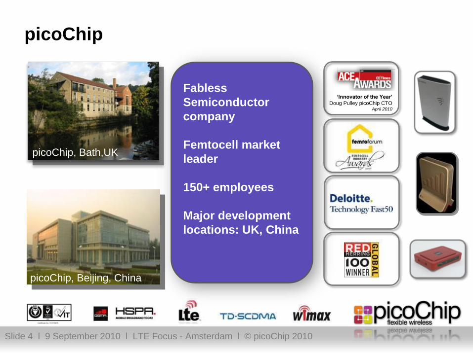
picoChip
picoChip, Bath,UK
picoChip, Beijing, China
Fabless
Semiconductor
company
Femtocell market
leader
150+ employees
Major development
locations: UK, China

Slide 5 l 9 September 2010 l LTE Focus - Amsterdam l © picoChip 2010
A what-o-cell? The traditional definition
femtocell - noun
a low-power domestic access point…
…using conventional mobile technology
…in licensed spectrum
…generating coverage
and capacity
…over internet-grade backhaul
…at prices comparable with Wi-Fi
access points
…with full operator management
Generic Femto Network Architecture

Slide 6 l 9 September 2010 l LTE Focus - Amsterdam l © picoChip 2010
High hopes to High Street…
Additional Countries launching…
Launched January 2010
Connects to Vodafone network
Minimum download speed 1MB per second
Up to 4 users at once (up to 32 can be registered)
National launch March 2010
Connects to AT&T network
Supports up to 4 voice or data users at once
Seamless call hand-over
Vodafone AT & T

Slide 7 l 9 September 2010 l LTE Focus - Amsterdam l © picoChip 2010
5 years of Industry Leadership
Demonstrated industry‟s first femtocell: 3GSM 2005
Coined the term „femtocell‟
First femtocell chip: PC202 in 2006
Founder members of Femto Forum
Elected to Board of Directors 2007 to date
Chair WG1 (Marketing)
Lead author for WG2 interference study (CDMA)
Co-lead author for WG2 interference study (OFDMA)
Active in 3GPP RAN – co-authored TRs on HNB and HeNB
First to demonstrate end-end IOT with 3rd party gateway
Commercial carrier launches:
Vodafone, AT&T, Softbank, SFR, etc
60+ in trials

Slide 8 l 9 September 2010 l LTE Focus - Amsterdam l © picoChip 2010
but femtocells are not just for Christmas…
Rural
Residential Metro
Enterprise
Slide 9 l 9 September 2010 l LTE Focus - Amsterdam l © picoChip 2010
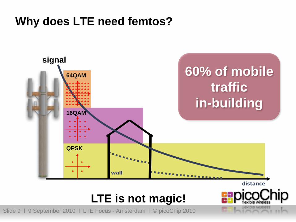
Why does LTE need femtos?
QPSK
16QAM
signal
distance
wall
64QAM 60% of mobile
traffic
in-building
LTE is not magic!

Slide 10 l 9 September 2010 l LTE Focus - Amsterdam l © picoChip 2010
“A game of two halves”: 3GPP Cell Specification
Base station class Minimum coupling loss
Wide Area 70dB
Medium Range (WCDMA not LTE) 53dB
Local Area 45dB
H(e)NB 45dB (assumed not specified)
Slide 11 l 9 September 2010 l LTE Focus - Amsterdam l © picoChip 2010
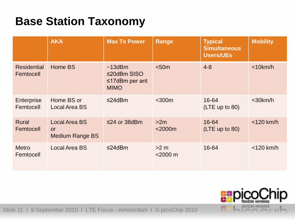
Base Station Taxonomy
AKA Max Tx Power Range Typical
Simultaneous
Users/UEs
Mobility
Residential
Femtocell
Home BS ~13dBm
≤20dBm SISO
≤17dBm per ant
MIMO
<50m 4-8 <10km/h
Enterprise
Femtocell
Home BS or
Local Area BS
≤24dBm <300m 16-64
(LTE up to 80)
<30km/h
Rural
Femtocell
Local Area BS
or
Medium Range BS
≤24 or 38dBm >2m
<2000m
16-64
(LTE up to 80)
<120 km/h
Metro
Femtocell
Local Area BS ≤24dBm >2 m
<2000 m
16-64 <120 km/h

Slide 12 l 9 September 2010 l LTE Focus - Amsterdam l © picoChip 2010
So how does a femtocell work…
plug-in and turn on
listens to network environment
adjusts: power levels; carrier; codes
self organizes into mobile network (SON)
connects through broadband
ipsec tunnel established to carrier
remote management
provides private mobile broadband cell
your coverage
your capacity
And what does this mean in LTE HeNB?

Slide 13 l 9 September 2010 l LTE Focus - Amsterdam l © picoChip 2010
LTE Self Organising Networks: SON
eNB power on
(or cable connected)
(A) Basic Setup
(B) Initial Radio
Configuration
(C) Optimization /
Adaptation
a-1 : configuration of IP address
and detection of OAM
a-2 : authentication of eNB/NW
a-3 : association to aGW
a-4 : downloading of eNB software
(and operational parameters)
b-2 : coverage/capacity related
parameter configuration
b-1 : neighbour list configuration
c-1 : neighbour list optimisation
c-2 : coverage and capacity control
Self-Configuration
(pre-operational state)
Self-Optimisation
(operational state)
But what if you have millions of self-installed eNBs?

Slide 14 l 9 September 2010 l LTE Focus - Amsterdam l © picoChip 2010
SON Functionality
SON covers a number of operations:
Self Configuration
This can be a periodic event determined by the network operator.
It uses OAM data and NMM measurements for the configuration
procedure
Self Optimisation
This is a continuous process where extra data us gathered from e.g.
UE Measurements, to optimise parameters used in the femtocell
Aimed at optimisations for local dynamic conditions
Stays within OAM parameters
Self Healing
To deal with unusual circumstances such as frequent switching of
UE between Macro and Home eNodeB.
Self Maintenance, Self Planning, Self Tuning etc..

Slide 15 l 9 September 2010 l LTE Focus - Amsterdam l © picoChip 2010
Femtocell Access Point SON/RRM Technology:
Where it comes from and goes to..
Deployment Modelling
FAPIOT and
Carrier Integration
FF Recommendations
3GPP H(e)NB Recommendations
System Test
and
Verification

Slide 16 l 9 September 2010 l LTE Focus - Amsterdam l © picoChip 2010
Provisioning and OA&M
Zero Touch Installation
Femtocell configuration via OA&M
Slide 17 l 9 September 2010 l LTE Focus - Amsterdam l © picoChip 2010
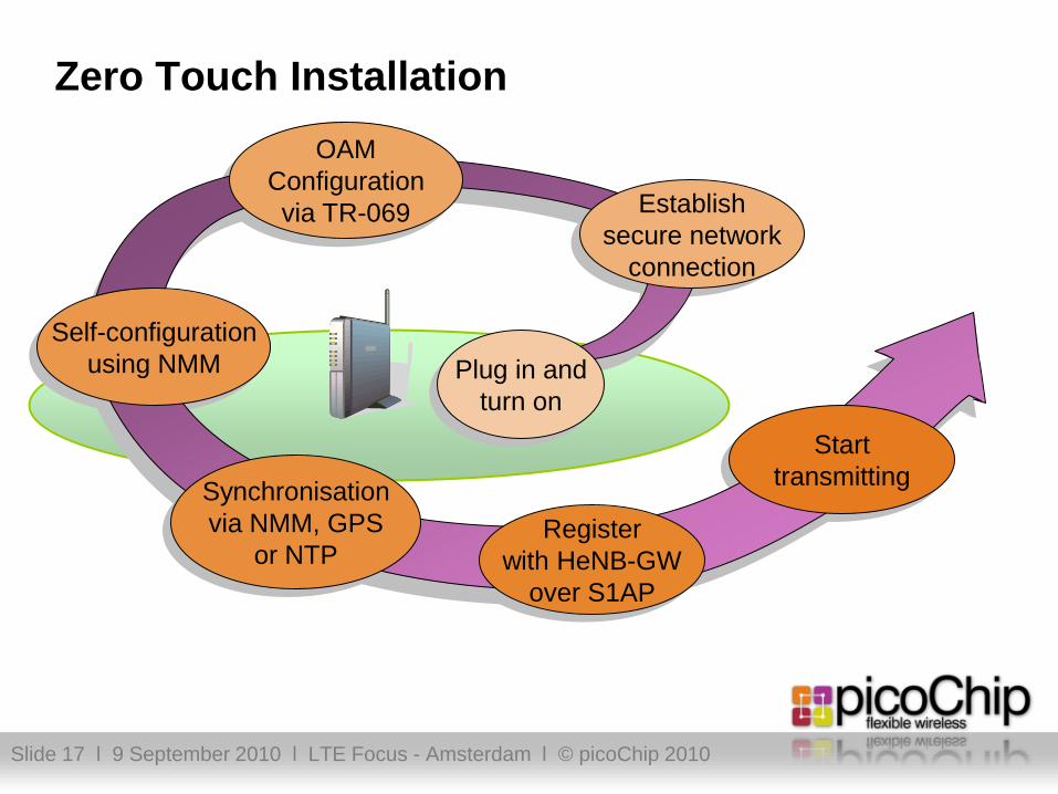
Zero Touch Installation
Plug in and
turn on
Register
with HeNB-GW
over S1AP
Establish
secure network
connection
Synchronisation
via NMM, GPS
or NTP
Self-configuration
using NMM
OAM
Configuration
via TR-069
Start
transmitting

Slide 18 l 9 September 2010 l LTE Focus - Amsterdam l © picoChip 2010
Zero Touch Installation
Zero Touch Installation combines the various aspects of
FAP application software in addition to other hardware
functions such as NMM to allow Home eNodeB to be self
configured after power up
Some aspects of Zero Touch Installation can be done on
a more frequent basis such as:
OAM data arriving from network
NMM updates
Synchronisation updates
Etc..
Slide 19 l 9 September 2010 l LTE Focus - Amsterdam l © picoChip 2010
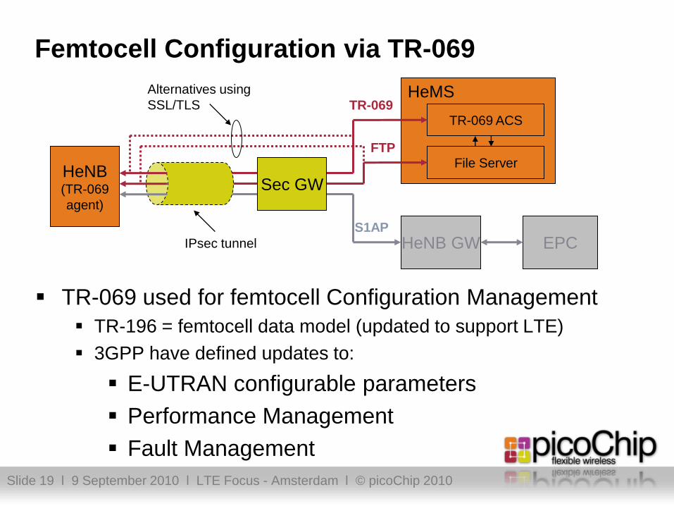
Femtocell Configuration via TR-069
TR-069 used for femtocell Configuration Management
TR-196 = femtocell data model (updated to support LTE)
3GPP have defined updates to:
E-UTRAN configurable parameters
Performance Management
Fault Management
HeNB(TR-069
agent)
HeNB GW
HeMS
TR-069 ACS
EPC
File Server
Sec GW
IPsec tunnel
TR-069
FTP
S1AP
Alternatives using
SSL/TLS

Slide 20 l 9 September 2010 l LTE Focus - Amsterdam l © picoChip 2010
Femtocell Synchronisation
A howto

Slide 21 l 9 September 2010 l LTE Focus - Amsterdam l © picoChip 2010
Why is it required?
Handover
Handsets do not follow same frequency requirements as Base stations
Handsets derive accurate frequency from Base stations
If femto and macro are not synchronised, HO may fail or call is disrupted
Network Interference
There can also be issues of interference between networks, typically reducing the call quality and network capacity
Frequency accuracy also allows the femtocell to “sniff out” adjacent cell sites, ensuring good behaviour to reduce interference
BS Class Frequency Accuracy
Wide Area 50 ppb
Local Area 100 ppb
Home 250 ppb

Slide 22 l 9 September 2010 l LTE Focus - Amsterdam l © picoChip 2010
Available Timing References Timing over Packet
“Enhanced” NTP
(Network Time Protocol)
GPS signal
Indoor solutions available in the
market
Broadcast information
Adjacent macro cells
GSM
WCDMA
LTE
TV
INTERNET
NTP
Master
GPS
device
NTP
client
NTP
client
2G Macro
3G Macro
Radio
Scan
4G Macro
Slide 23 l 9 September 2010 l LTE Focus - Amsterdam l © picoChip 2010
Femtocell Handovers
Outbound (femtocell to macrocell)
Inbound (macrocell to femtocell)
Femtocell to femtocell
Slide 24 l 9 September 2010 l LTE Focus - Amsterdam l © picoChip 2010
Femtocell Handover
HeNBs have been built into LTE from the beginning
The UE understands the concepts of:
HeNB name (SIB 9)
CSG IDs (SIB 1)
Open/closed access (SIB 1)
CSG physical cell ID range (SIB 4)
In connect mode handover controlled by (H)eNB based on
measurements from UE and/or network loading
In idle mode, UEs have an autonomous search function to
find HeNBs
Handover to UMTS, GSM and CDMA2000 also defined

Slide 25 l 9 September 2010 l LTE Focus - Amsterdam l © picoChip 2010
Femto-to-Macro Outbound Handover
Same principle as existing macro-to-macro handover. But
no X2 interface, so signalling is via S1
HeNB HeNB
HeNB-GW
EPC
eNB
S1
S1

Slide 26 l 9 September 2010 l LTE Focus - Amsterdam l © picoChip 2010
Macro-to-Femto Inbound Handover
Same principle as existing macro-to-macro handover. But no X2 interface, so signalling is via S1 UE autonomously detects HeNBs.
HeNBs have an unique Physical Cell ID within the macrocell the UE is currently connected
Release 9 defines how macrocell identifies femtocells where UE is CSG member
PhysCell_Id1
PhysCell_Id4
PhysCell_Id2 PhysCell_Id3

Slide 27 l 9 September 2010 l LTE Focus - Amsterdam l © picoChip 2010
Femto-to-Femto Handover
Same principle as existing macro-to-macro handover
Handled entirely within the HeNB-GW, via S1
If supported X2 could be used for handover
HeNB
HeNB-GW
HeNB
S1
HeNB
HeNB
S1
Part of the same
CSG – eg
enterprise or
campus

Slide 28 l 9 September 2010 l LTE Focus - Amsterdam l © picoChip 2010
Interference Mitigation
Keep the noise down!

Slide 29 l 9 September 2010 l LTE Focus - Amsterdam l © picoChip 2010
Deployment Considerations
Femto UE Femto AP
Shared or Dedicated carrier Neighbour
macrocell
Macro UE
Open, Closed or Hybrid Access
“Hybrid” access added in Rel-9 – allows all
UEs access the femto but gives priority
(higher QoS, etc) to those in the “Closed
Subscriber Group”
Femto can be on a dedicated
carrier frequency or co-channel
with macro layer.
Separation between Femto AP
and macrocell
Indoors or outdoors
Indoors or outdoors

Slide 30 l 9 September 2010 l LTE Focus - Amsterdam l © picoChip 2010
Interference Scenarios – Detailed Case
1
UE Registered in HeNB is radiating at a power level that can be received by the Macro eNodeB
This is received as noise by Macro eNodeB and makes it more difficult to listen to the UEs camping on it
Depending on the interference level, Macro eNodeB would tell UEs to raise their power levels

Slide 31 l 9 September 2010 l LTE Focus - Amsterdam l © picoChip 2010
Interference Scenarios
UE attached to Home eNode BHome eNode B6
Home eNode BUE attached to Home eNode B5
UE attached to Home eNode BMacro eNode B4
Home eNode BUE attached to Macro eNode B3
UE attached to Macro eNode BHome eNode B2
Macro eNode BUE attached to Home eNode B1
VictimAggressor
1
2
3
46
5
Attached
BS Victim
UE Victim

Slide 32 l 9 September 2010 l LTE Focus - Amsterdam l © picoChip 2010
Deployment Modelling and Simulation
To determine algorithms and parameter values, extensive
simulation is necessary
picoChip has developed two in-house simulation systems
necessary for evaluating deployment issues:
macro/femto network co-existence
indoor femtocell performance
These have been used to provide results for activities in
Femtoforum and 3GPP on WCDMA, LTE and TDSCDMA
systems and benchmarked with other leaders

Slide 33 l 9 September 2010 l LTE Focus - Amsterdam l © picoChip 2010
Macro/Femto Coexistence Simulator
Can test many scenarios:
co-channel/adjacent channel
open, closed and hybrid acccess
Can test:
interference mitigations
RF design parameters
Can determine:
femto network performance
any macro impairments
…
Slide 34 l 9 September 2010 l LTE Focus - Amsterdam l © picoChip 2010
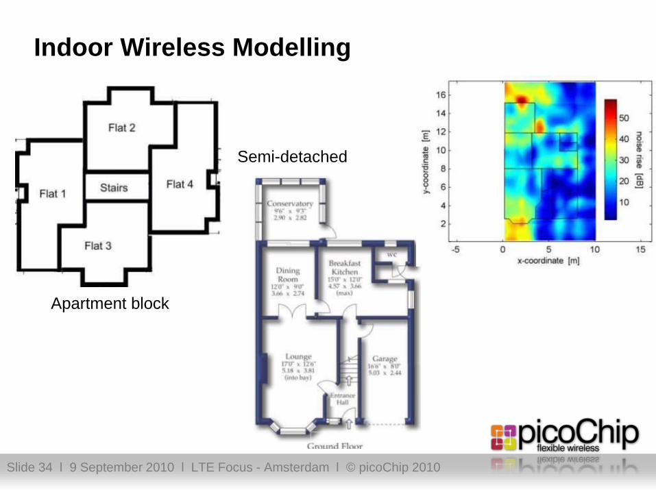
Indoor Wireless Modelling
Apartment block
Semi-detached

Slide 35 l 9 September 2010 l LTE Focus - Amsterdam l © picoChip 2010
System Modelling
Femto Houses or apartments dropped within macro coverage area
house
Max UE area
Max femto BS area
10 m
10 m
10 m
10 m
10 m
2 apartment “stripes” with multiple floors
house
Slide 36 l 9 September 2010 l LTE Focus - Amsterdam l © picoChip 2010
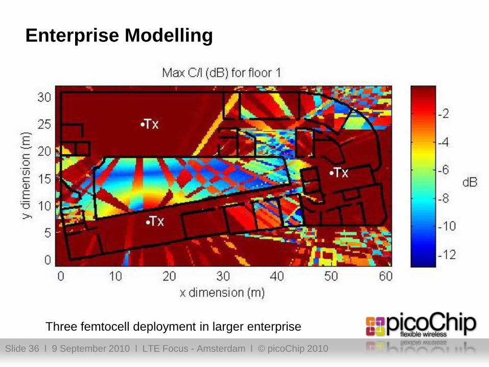
Enterprise Modelling
Three femtocell deployment in larger enterprise

Slide 37 l 9 September 2010 l LTE Focus - Amsterdam l © picoChip 2010
Scenario 2: Femto to Macro Downlink: Macro Deadzone
Femto UE
Femto AP
Femto coverage area
Femto downlink SINR > threshold
Macro Deadzone
Macro DL SINR < threshold
Neighbour
macrocell
Slide 38 l 9 September 2010 l LTE Focus - Amsterdam l © picoChip 2010
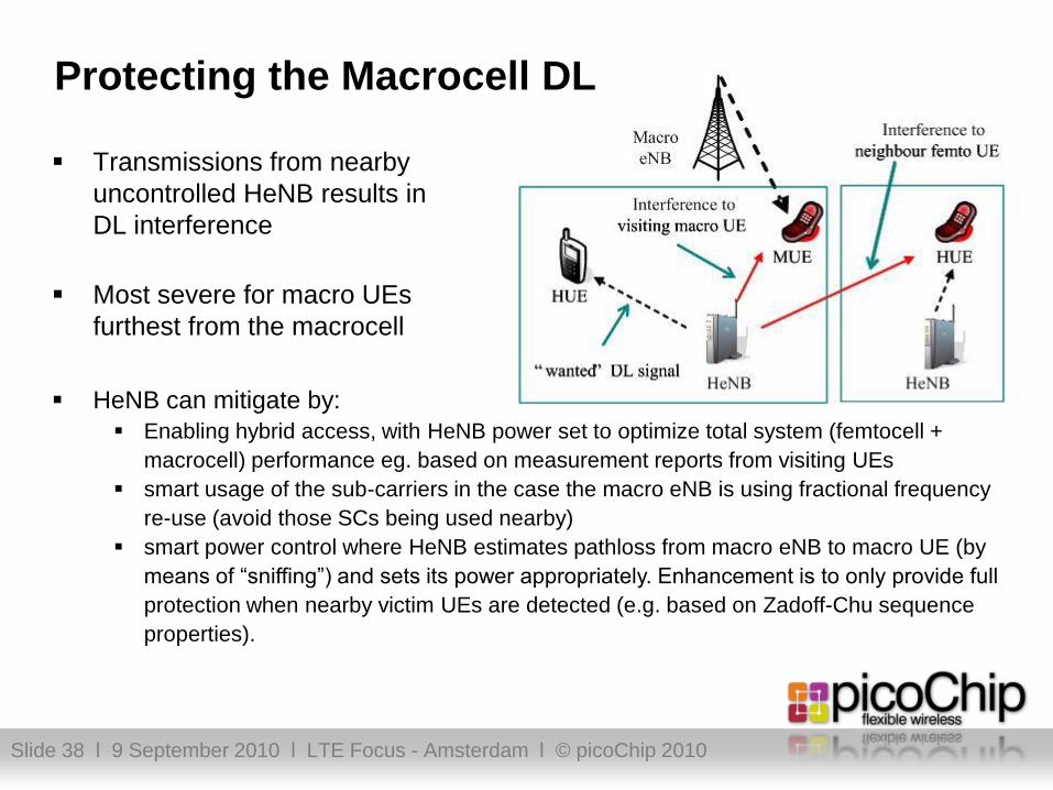
Protecting the Macrocell DL
Transmissions from nearby
uncontrolled HeNB results in
DL interference
Most severe for macro UEs
furthest from the macrocell
HeNB can mitigate by:
Enabling hybrid access, with HeNB power set to optimize total system (femtocell +
macrocell) performance eg. based on measurement reports from visiting UEs
smart usage of the sub-carriers in the case the macro eNB is using fractional frequency
re-use (avoid those SCs being used nearby)
smart power control where HeNB estimates pathloss from macro eNB to macro UE (by
means of “sniffing”) and sets its power appropriately. Enhancement is to only provide full
protection when nearby victim UEs are detected (e.g. based on Zadoff-Chu sequence
properties).

Slide 39 l 9 September 2010 l LTE Focus - Amsterdam l © picoChip 2010
Network Monitor Mode (aka “sniffer”)
Measurement Type Purpose
Co-channel RSRP Setting femto Tx power for desired coverage and
protection of co-channel MUEs (incl. hybrid access)Co-channel RSRQ
Adjacent-channel carrier RSRPSetting femto Tx power for protection of adjacent-
channel MUEs, including adjacent channel operatorsAdjacent-channel ref signal Rx
power
Uplink Ref Signal Detection Detection of Victim UEs
Read system info Tx power (for pathloss calc), CSG status, Cell ID etc.
Transmitter
Receiver
DL
UL
Duplexer
DL Rx
UL Rx
DAC
ADC
Baseband
PHY &
NMM
Slide 40 l 9 September 2010 l LTE Focus - Amsterdam l © picoChip 2010
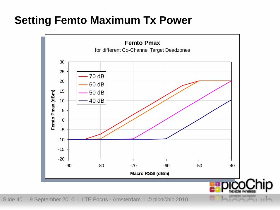
Setting Femto Maximum Tx Power
Femto Pmaxfor different Co-Channel Target Deadzones
-20
-15
-10
-5
0
5
10
15
20
25
30
-90 -80 -70 -60 -50 -40
Macro RSSI (dBm)
Fem
to P
max (
dB
m)
70 dB
60 dB
50 dB
40 dB

Slide 41 l 9 September 2010 l LTE Focus - Amsterdam l © picoChip 2010
Adjacent Operator Protection
Some signal power from the
femtocell leaks into the adjacent
channel, according to its ACLR
and the MUE ACS
3GPP Requirement:
If the adjacent channel belongs to a
different operator, the femto must limit
its transmit power to minimise
interference to that operator
Femto Tx
Channel
Adjacent
Channel
Femto
transmit
spectrum
ACLR
UE receive
filter
ACS

Slide 42 l 9 September 2010 l LTE Focus - Amsterdam l © picoChip 2010
Protecting the Macrocell UL
Transmissions from femto UEs
results in a higher level of UL
interference at macro eNB
Impact most severe if HeNB
close to macro eNB.
Impact increases with femto
density.
◘ Femto can mitigate by:◘ Power control of its UEs based on pathloss estimates to limit “noise
rise” at macro eNB to acceptable value. Ideally make adaptive e.g.
acceptable noise rise per HeNB is a function of HeNB density.
Requires feedback from macro eNB (e.g. via X2 in future releases).
◘ For PUCCH control channel, femto could use different set of
subcarriers than the macro.

Slide 43 l 9 September 2010 l LTE Focus - Amsterdam l © picoChip 2010
Use of X2
Macro
eNB
Macro
eNB
X2
Proxy
Home
eNB
Home
eNB
Home
eNB
Home
eNB
X2 Load Indications
X2 Load Indications
X2 Load Indications
One potential issue is that there could be a large number of femtos within the
macro coverage area which could lead to complexity issues at the macro eNB if
each femto had an X2 interface to the macro eNB
Two possible approaches to solving this
Have an X2 “concentration” function in an X2 proxy or gateway
Only send load indications in the direction from the macro to the femtos, rather than
being bidirectional
Slide 44 l 9 September 2010 l LTE Focus - Amsterdam l © picoChip 2010
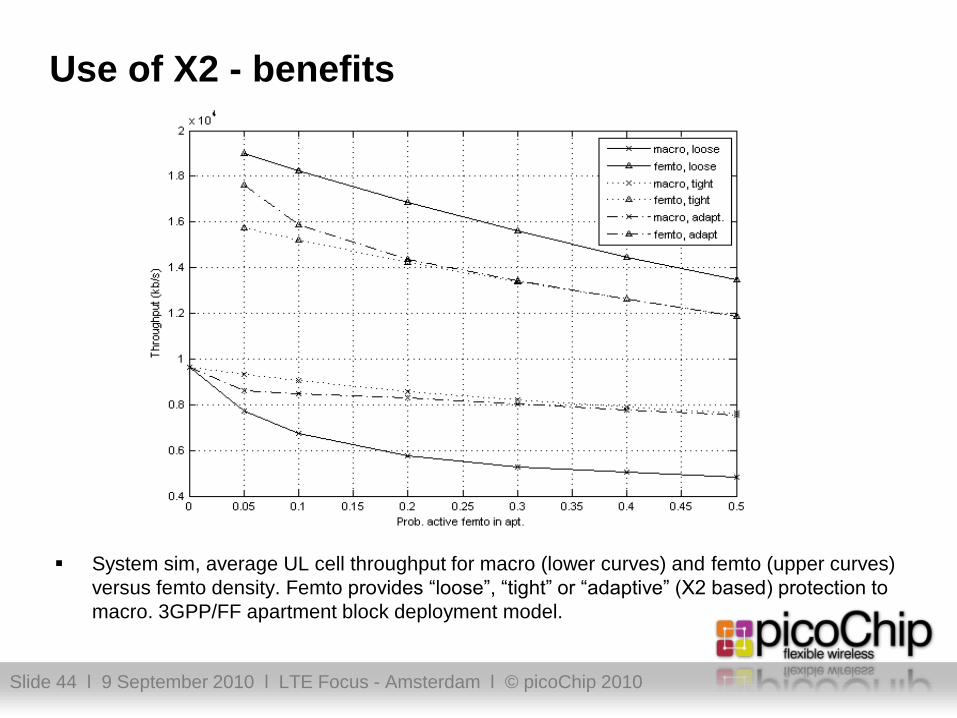
Use of X2 - benefits
System sim, average UL cell throughput for macro (lower curves) and femto (upper curves)
versus femto density. Femto provides “loose”, “tight” or “adaptive” (X2 based) protection to
macro. 3GPP/FF apartment block deployment model.

Slide 45 l 9 September 2010 l LTE Focus - Amsterdam l © picoChip 2010
Protecting the Femtocell Uplink
Transmissions from nearby uncontrolled UEs results in a higher level of UL interference
Reflected in TS36.104 tests for Dynamic Range and ACS – upper limits increased for HeNB
Femto can mitigate with dynamic control of the receiver gain
Reduce gain to temporarily accommodate higher interference
Also known as adaptive noise figure
Attached femto UEs will power up to overcome interference
Small path loss to femto means UE have plenty of power headroom

Slide 46 l 9 September 2010 l LTE Focus - Amsterdam l © picoChip 2010
Protecting the Femtocell Downlink (femto-femto)
Transmissions from nearby uncontrolled HeNB results in DL
interference
HeNB can mitigate by using a sub-set of sub-carriers not being used
by other nearby HeNB. Both centralized control (e.g. at HeNB GW) or
control at individual HeNBs has been considered by RAN4

Slide 47 l 9 September 2010 l LTE Focus - Amsterdam l © picoChip 2010
Interference Mitigation Summary
DL interference to UEs attached to Macro eNodeB or neighboring HeNB
Adaptive transmit power control based on measurements of co-channel and
adjacent-channel macro signal strength and/or smart usage of subcarriers.
“Sniffer” (aka Network Monitor Mode) functionality in HeNB to measure Macro
DL transmissions
Enhancements based on nearby victim UE detection by HeNB
Balance required femto against macro performance, which may change with
hybrid access femtocells
UL interference to Macro Node B
Implement UE “power cap” based on estimate of path loss to macro eNode B
Ideally the power cap should be adaptive such that interference contribution
from individual HeNB is function of HeNB density
Support for X2 between macro eNodeB and HeNB desirable in future 3GPP
releases

Slide 48 l 9 September 2010 l LTE Focus - Amsterdam l © picoChip 2010
Dr Doug PulleyCTO & co-Founder
picoChip LtdAddress: Riverside Buildings, 108 Walcot Street, Bath, BA1 5BG
Email: [email protected]
Website: www.picochip.com
Slide 49 l 9 September 2010 l LTE Focus - Amsterdam l © picoChip 2010