Embed Size (px)
Citation preview
1
如何测量您的LTE下行信号
Agenda
What the Downlink has to do
Detailed downlink channel analysis
Agilent Equipment used
Q & A
2
When It’s Valuable To Understand the DL signal
• You are building the baseband signal and need to independently verify it
• You are feeding an unknown base station signal into a UEYou are feeding an unknown base station signal into a UE receiver and want to check what’s in the signal
• You have a low level interoperability problem
• You want to understand the structure of the downlink signal
• You want to find out why throughput results are not as high• You want to find out why throughput results are not as high as you were expecting (track the HARQ processes in DL or UL)
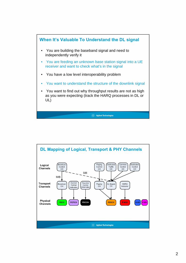
DL Mapping of Logical, Transport & PHY Channels

3
LTE Air Interface:Downlink Physical Channels (1 of 2)
PBCH – Physical Broadcast ChannelBroadcast Channel
PCFICH Physical Control Format Indicator ChannelIndicator Channels
BaseStation
(eNB)
UserEquipment
(UE)
PBCH: - Carries cell specific information such as system bandwidth, number of Tx
antennas etc…- Transmitted in the centre 72 subcarriers (6 RB) around DC at OFDMA symbol #0 to
#3 of Slot #1 of sub-frame #0- Modulation scheme = QPSK
PCFICH:- Carries information on the number of OFDM symbols used for transmission of
PCFICH – Physical Control Format Indicator Channel
PHICH –Physical Hybrid-ARQ Indicator Channel
- Carries information on the number of OFDM symbols used for transmission of PDCCH’s in a sub-frame
- Transmitted on symbol #0 of slot 0 in a sub-frame- Modulation scheme = QPSK
PHICH:- Carries the hybrid-ARQ ACK/NACK feedback to the UE for the blocks received - Transmitted on symbol #0 of every sub-frame (Normal duration) and symbols #0, 1
& 2 of every sub-frame (Extended duration) if the number of PDCCH symbols = 3 - Modulation scheme = BPSK (CDM)
LTE Air Interface:Downlink Physical Channels (2 of 2)
PDCCH – Physical Downlink Control ChannelControl Channel
Sh d (P l d) Ch l
BaseStation
(eNB)
UserEquipment
(UE)
PDCCH
- Carries uplink and downlink scheduling assignments and other control information depending on format type (there are 4 formats)
- Transmitted on the first 1, 2 or 3 symbols of every subframe - Modulation scheme = QPSK
PDSCH - Physical Downlink Shared ChannelShared (Payload) Channel
PDSCH- Carries downlink user data- Transmitted on sub-carriers and symbols not occupied by
the rest of downlink channels and signals - Modulation scheme = QPSK, 16QAM, 64 QAM
4
Agenda
What the Downlink has to do
Detailed downlink channel analysis
Agilent Equipment used
Q & A
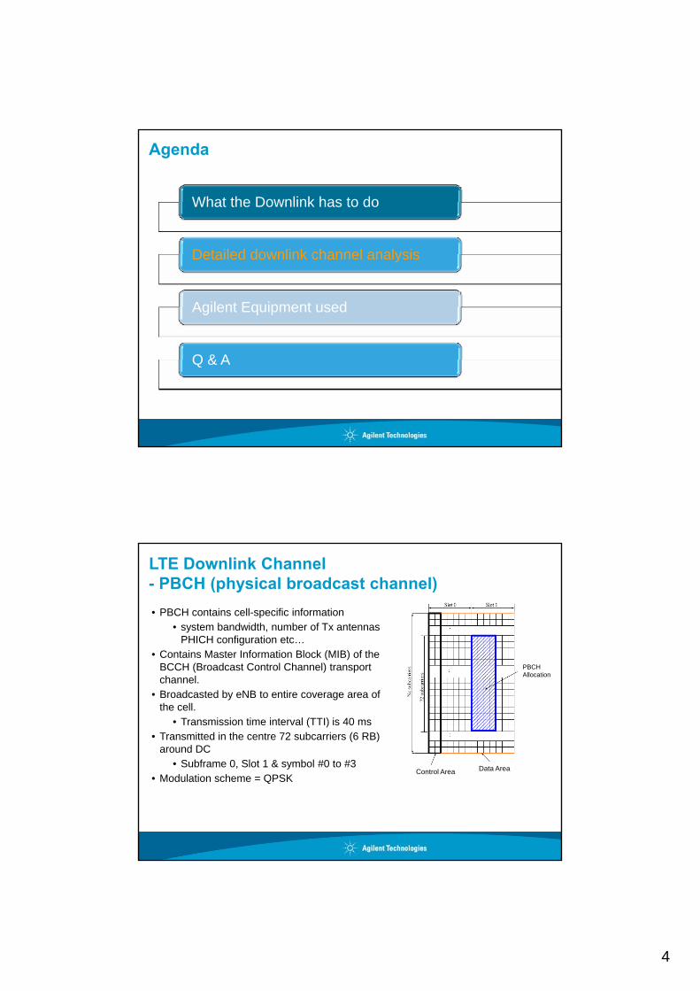
LTE Downlink Channel- PBCH (physical broadcast channel)• PBCH contains cell-specific information
• system bandwidth, number of Tx antennas PHICH configuration etc…
PBCH Allocation
• Contains Master Information Block (MIB) of the BCCH (Broadcast Control Channel) transport channel.
• Broadcasted by eNB to entire coverage area of the cell.
• Transmission time interval (TTI) is 40 ms• Transmitted in the centre 72 subcarriers (6 RB)
around DC
Data AreaControl Area• Subframe 0, Slot 1 & symbol #0 to #3
• Modulation scheme = QPSK
5
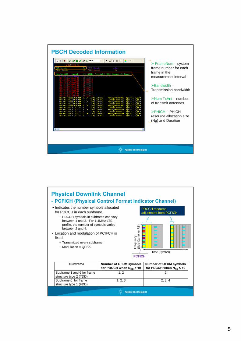
PBCH Decoded Information
FrameNum – system frame number for each frame in the measurement interval
Bandwidth –Transmission bandwidth
Num TxAnt – number of transmit antennas
PHICH – PHICH resource allocation size (Ng) and Duration
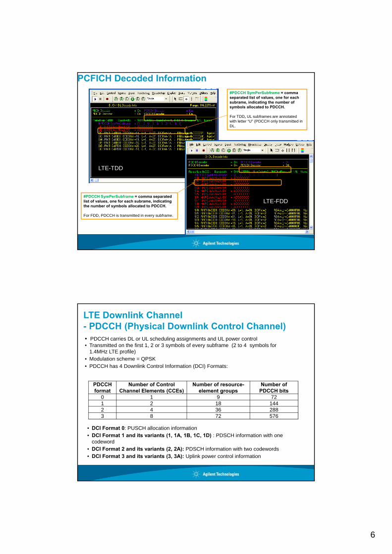
Physical Downlink Channel- PCFICH (Physical Control Format Indicator Channel)• Indicates the number symbols allocated
for PDCCH in each subframe. • PDCCH symbols in subframe can vary
between 1 and 3. For 1.4MHz LTE
PDCCH resource adjustment from PCFICH
profile, the number of symbols varies between 2 and 4.
• Location and modulation of PCIFCH is fixed.
• Transmitted every subframe. • Modulation = QPSK
Time (Symbol)
Freq
uenc
y (S
ub-C
arrie
r or R
B)
PCFICH
Subframe Number of OFDM symbols for PDCCH when NRB > 10
Number of OFDM symbols for PDCCH when NRB ≤ 10
Subframe 1 and 6 for frame structure type 2 (TDD)
1, 2 2
Subframe 0 for frame structure type 1 (FDD)
1, 2, 3 2, 3, 4
6
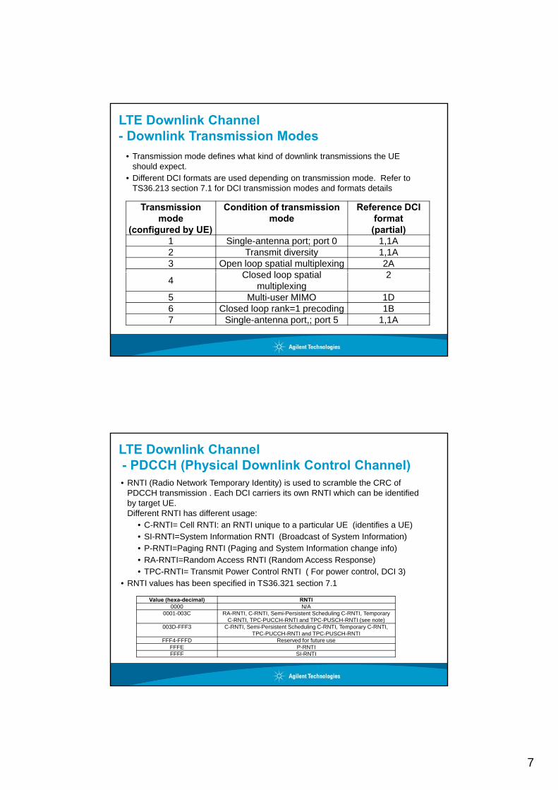
PCFICH Decoded Information#PDCCH SymPerSubframe = comma separated list of values, one for each subrame, indicating the number of symbols allocated to PDCCH.
For TDD, UL subframes are annotated with letter “U” (PDCCH only transmitted in DL.
LTE-TDD
#PDCCH SymPerSubframe = comma separated list of values, one for each subrame, indicating the number of symbols allocated to PDCCH.
For FDD, PDCCH is transmitted in every subframe.
LTE-FDD
LTE Downlink Channel- PDCCH (Physical Downlink Control Channel)• PDCCH carries DL or UL scheduling assignments and UL power control• Transmitted on the first 1, 2 or 3 symbols of every subframe (2 to 4 symbols for
1.4MHz LTE profile)• Modulation scheme = QPSK• PDCCH has 4 Downlink Control Information (DCI) Formats:
PDCCH format
Number of Control Channel Elements (CCEs)
Number of resource-element groups
Number of PDCCH bits
0 1 9 721 2 18 1442 4 36 2883 8 72 576
• DCI Format 0: PUSCH allocation information• DCI Format 1 and its variants (1, 1A, 1B, 1C, 1D) : PDSCH information with one
codeword• DCI Format 2 and its variants (2, 2A): PDSCH information with two codewords• DCI Format 3 and its variants (3, 3A): Uplink power control information
7
LTE Downlink Channel- Downlink Transmission Modes
• Transmission mode defines what kind of downlink transmissions the UE should expect.
• Different DCI formats are used depending on transmission mode. Refer to TS36 213 section 7 1 for DCI transmission modes and formats detailsTS36.213 section 7.1 for DCI transmission modes and formats details
Transmission mode
(configured by UE)
Condition of transmission mode
Reference DCI format(partial)
1 Single-antenna port; port 0 1,1A2 Transmit diversity 1,1A3 Open loop spatial multiplexing 2A
Cl d l ti l 24 Closed loop spatial multiplexing
2
5 Multi-user MIMO 1D6 Closed loop rank=1 precoding 1B7 Single-antenna port,; port 5 1,1A
LTE Downlink Channel- PDCCH (Physical Downlink Control Channel)• RNTI (Radio Network Temporary Identity) is used to scramble the CRC of
PDCCH transmission . Each DCI carriers its own RNTI which can be identified by target UE. Different RNTI has different usage: g
• C-RNTI= Cell RNTI: an RNTI unique to a particular UE (identifies a UE)• SI-RNTI=System Information RNTI (Broadcast of System Information)• P-RNTI=Paging RNTI (Paging and System Information change info)• RA-RNTI=Random Access RNTI (Random Access Response)• TPC-RNTI= Transmit Power Control RNTI ( For power control, DCI 3)
• RNTI values has been specified in TS36.321 section 7.1
Value (hexa-decimal) RNTIValue (hexa decimal) RNTI0000 N/A
0001-003C RA-RNTI, C-RNTI, Semi-Persistent Scheduling C-RNTI, Temporary C-RNTI, TPC-PUCCH-RNTI and TPC-PUSCH-RNTI (see note)
003D-FFF3 C-RNTI, Semi-Persistent Scheduling C-RNTI, Temporary C-RNTI, TPC-PUCCH-RNTI and TPC-PUSCH-RNTI
FFF4-FFFD Reserved for future useFFFE P-RNTIFFFF SI-RNTI

8
PDCCH Decoded Information
DCI Format = 2, employing Closed loop spatial multiplexing
see backup slide for description of the other decoded information
Physical Downlink Channel- PHICH (Physical Hybrid ARQ Indicator Channel)• Contains Hybrid Indication (HI) control information• Indicates in the DL direction whether an uplink
packet was correctly received or not• UE decodes PHICH based on the UL allocation• UE decodes PHICH based on the UL allocation
information received on PDCCH• Transmitted in every subframe• Modulation – BPSK• Multiple PHICHs mapped to the same set of
resource elements (sub-carriers) form a PHICH group. PHICH ithi th PHICH
210 ,, bbb
1/3 rate RepeatitionCoding
3GPP TS 36 212 Figure 5 3 5 1
BPSK Modulation
• PHICHs within the same PHICH group are separated through different orthogonal sequences.
3GPP TS 36.212 Figure 5.3.5-1
HI = 0: NACKHI = 1: ACK
9
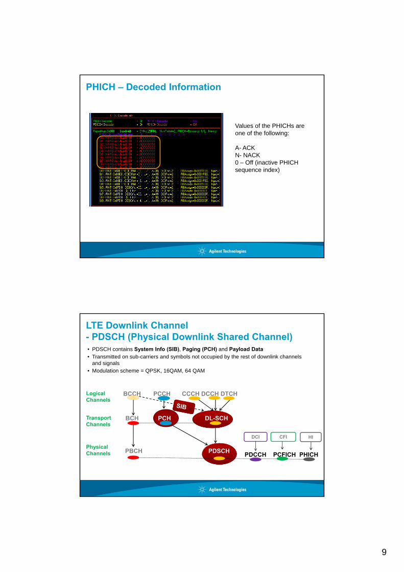
PHICH – Decoded Information
Values of the PHICHs are one of the following:g
A- ACKN- NACK0 – Off (inactive PHICH sequence index)
LTE Downlink Channel- PDSCH (Physical Downlink Shared Channel)• PDSCH contains System Info (SIB), Paging (PCH) and Payload Data• Transmitted on sub-carriers and symbols not occupied by the rest of downlink channels
and signals • Modulation scheme = QPSK, 16QAM, 64 QAM
Logical Channels
BCCH PCCH CCCH DCCH DTCH
Transport Channels
BCH PCH DL-SCH
DCI CFI HI
Physical Channels PBCH PDSCH PDCCH PCFICH PHICH
DCI CFI HI

10
PDSCH Decoded Information
SA & SS Downlink Channel (De)coding SummaryDL Channel Content Signal Studio Auto-
Encoding Status89600 VSA Decoding Status
PBCH MIB System Info Supported Supported
PCFICH Num PDCCH Symbols
Supported SupportedSymbols
PHICH HARQ ACK/NACK Supported (user-defined RV index sequence is possible)
Supported(auto detects PHICH Sequence activityreporting Ack / Nack / Off values within DL Decode Info trace)
PDCCH DL & UL Scheduling,Power Control
Supported (supports PDSCH allocation, UE sched, UE RA, UE power
Supported(auto detects any RNTI and any of DCI Formats 0, 1, 1A, 1B, 1C, 1D, 2, 2A, 3,
control), , , C, , , , 3,
3A)
PDSCH System Info (SIB),Paging, Payload Data
Supported (all allocation types)
Supported(auto detects any Type 0, 1, 2 Bitmapped, Localized and Distributed RB allocation, and decodes PDSCH CRC = Pass/Failresult)

11
Agenda
What the Downlink has to do
Detailed downlink channel analysis
Agilent Equipment used
Q & A
89600B VSA Signal Analysis
• In-depth analog and demodulated signal analysis• Extensive Downlink & Uplink decodinggOption BHD FDDOption BHE TDD

12
X-Series N9080A/82A: LTE FDD/TDD Measurement Applications
• Supports 3GPP Mar-09 LTE standard• Embedded solution with SCPI Programming• One-button power measurements (ACLR, SEM,
etc..) with standard presets• Setup files for All E-UTRA Test Models• Downlink (OFDMA) and uplink (SC-FDMA)
analysis in a single option• All LTE bandwidths: 1.4 MHz to 20 MHz• All LTE modulation types and sequences: BPSK,
QPSK, 16QAM, 64QAM, Zadoff-Chu• Analyzes Tx diversity plus timing and phase offset y y p g p
measurements for MIMO signals• Supports Agilent X-Series (PXA/MXA/EXA) Signal
Analyzers
Signal Generation & Analysis – Higher Order MIMO
Signal generation:
Downlink 8x8 & uplink 4x4 is not available today; under investigationUp to 4x4 downlink MIMO is available using existing LTE solutions
Signal Analysis:Signal Analysis:Downlink 8x8 MIMO & uplink 4x4 MIMO not available at initial releaseUp to 4x4 downlink MIMO is available using existing LTE solutionsFuture 8x8 MIMO solution will be based on N7109A hardware. Timing to be determinedX-Series analyzers are not optimum choice for LTE-Advanced MIMO due to:
Limitation to 2x2 MIMO using dual MXA or EXA. Most LTE-Advanced customers will be interested in higher than 2x2 MIMO.Dual MXA or EXA is not supported with 40 MHz bandwidth and dual PXA is not currentlyDual MXA or EXA is not supported with 40 MHz bandwidth and dual PXA is not currently supported.
Do you have customers working on 8x8 MIMO today? If so, we would love to hear from you!
13
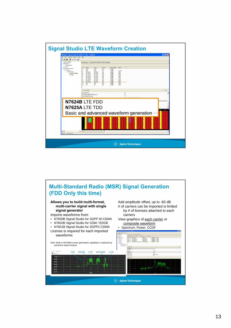
Signal Studio LTE Waveform Creation
N7624B LTE FDDN7625A LTE TDDBasic and advanced waveform generationBasic and advanced waveform generation
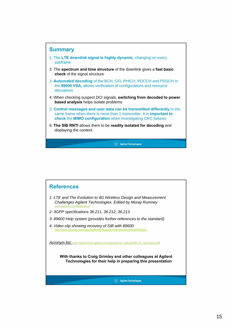
Multi-Standard Radio (MSR) Signal Generation(FDD Only this time)Allows you to build multi-format,
multi-carrier signal with single signal generator
Imports waveforms from:
Add amplitude offset, up to -60 dB# of carriers can be imported is limited
by # of licenses attached to each carriersImports waveforms from:
• N7600B Signal Studio for 3GPP W-CDMA• N7602B Signal Studio for GSM / EDGE• N7601B Signal Studio for 3GPP2 CDMALicense is required for each imported
waveforms
Note: Built-in WCDMA carrier generation capability is replaced by waveform import feature
carriersView graphics of each carrier or
composite waveform• Spectrum, Power, CCDF
LTE WCDMA C2KEDGECW

14
SystemVue System Design Software
W1910EP Baseband VerificationW1912ET Exploration
E6621A (MIMO) Real Time eNB Emulator
N6051A RF parametric test with test mode signalingN6051A RF parametric test with test mode signalingN6052A Functional and application testN6061A Protocol logging and analysisN6062A Message editor
15
Summary1: The LTE downlink signal is highly dynamic, changing on every
subframe
2: The spectrum and time structure of the downlink gives a fast basic check of the signal structure
3: Automated decoding of the BCH, CFI, PHICH, PDCCH and PDSCH in the 89600 VSA, allows verification of configurations and resource allocations
4: When checking suspect DCI signals, switching from decoded to power based analysis helps isolate problems
5: Control messages and user data can be transmitted differently in the same frame when there is more than 1 transmitter It is important tosame frame when there is more than 1 transmitter. It is important to check the MIMO configuration when investigating CRC failures
6: The SIB RNTI allows them to be readily isolated for decoding and displaying the content
References
1: LTE and The Evolution to 4G Wireless Design and Measurement Challenges Agilent Technologies. Edited by Moray Rumney www.agilent.com/find/ltebook
2: 3GPP specifications 36.211, 36.212, 36.213
3: 89600 Help system (provides further references to the standard)
4: Video clip showing recovery of SIB with 89600: http://www.youtube.com/user/agilentlte?feature=mhum#p/a/u/0/fVqPIsKejQs
Acronym list: http://www.home.agilent.com/upload/cmc_upload/All/LTE_Acronyms.pdf
With thanks to Craig Grimley and other colleagues at Agilent Technologies for their help in preparing this presentation


![An Experimental Evaluation of LTE-A Throughput for Drones...Paper Contribution Release Height TrafficThroughput UL Throughput DL Albaladejo et al. [3] Derived a model for throughput](https://img.dokumen.tips/doc/110x75/60d57bafed3211582b334085/an-experimental-evaluation-of-lte-a-throughput-for-drones-paper-contribution.jpg)