Embed Size (px)
Citation preview

LTE-A Cellular Networks

Abid Yahya
LTE-A Cellular Networks
Multi-hop Relay for Coverage, Capacityand Performance Enhancement
With contributions from
Jaafar A. Aldhaibani
R. Badlishah Ahmad
Joseph M. Chuma

Abid YahyaBIUSTBotswana International University of Science & TechnologyPalapye, Botswana
ISBN 978-3-319-43303-5 ISBN 978-3-319-43304-2 (eBook)DOI 10.1007/978-3-319-43304-2
Library of Congress Control Number: 2016949555
© Springer International Publishing Switzerland 2017This work is subject to copyright. All rights are reserved by the Publisher, whether the whole or part ofthe material is concerned, specifically the rights of translation, reprinting, reuse of illustrations,recitation, broadcasting, reproduction on microfilms or in any other physical way, and transmissionor information storage and retrieval, electronic adaptation, computer software, or by similar ordissimilar methodology now known or hereafter developed.The use of general descriptive names, registered names, trademarks, service marks, etc. in thispublication does not imply, even in the absence of a specific statement, that such names are exemptfrom the relevant protective laws and regulations and therefore free for general use.The publisher, the authors and the editors are safe to assume that the advice and information in thisbook are believed to be true and accurate at the date of publication. Neither the publisher nor theauthors or the editors give a warranty, express or implied, with respect to the material containedherein or for any errors or omissions that may have been made.
Printed on acid-free paper
This Springer imprint is published by Springer NatureThe registered company is Springer International Publishing AG SwitzerlandThe registered company address is Gewerbestrasse 11, 6330 Cham, Switzerland

Dedicated to my family for their love,support, and sacrifice along the path of myacademic pursuits
Abid Yahya
Dedicated to those exemplary personalitieswho strive for the betterment of mankindwithout personal gain
Jaafar A. Aldhaibani


Preface
Multi-hop relay is considered as one of the main keys for Long Term Evaluation—
Advanced (LTE-A) to meet the growing demand for coverage extension and
capacity enhancement. However, these benefits of multi-hop depend on the location
of Relay Node (RN) which mitigates interference among the cells.
This book consists of five chapters and is organized as follows:
Chapter 1 gives an overview, clarifying the issues and motivating aspect of the
research, together with the objectives, and overall book layout.
Chapter 2 provides a literature survey for various methods of relay deployment,
and updates the state of current developments and solutions in the field of relay
techniques, while evaluating the developments and solutions and critique of each
method.
Chapter 3 gives a detailed explanation of three mathematical modeling tech-
niques called Optimum RN Deployment (ORND), Enhance Relay Link Capacity
(ERLC), and Balance Power Algorithm (BPA) within LTE-A cellular networks.
ORND involves the mathematical derivation of the optimum RN location, an
allocation of transmitted power for each RN, the optimum number of RNs within
cell, the handover process, and the frequency reuse scheme. ERLC focuses on
performance analysis by employing two antenna types in the RN to enhance relay
link capacity. At the end of this chapter, the BPA is illustrated to minimize the
transmission power consumption for MR.
Chapter 4 details the results from mathematical formulations and compares it
with the simulation results in terms of spectral efficiency, coverage area, through-
put, and transmission power consumptions for the MR using BPA.
Chapter 5 presents optimum location for relay node in LTE-A. This chapter
concludes the originality and innovations with a summary of the results.
Palapye, Botswana Abid Yahya
Jaafar A. Aldhaibani
R. Badlishah Ahmad
Joseph M. Chuma
vii


Acknowledgments
Thank you to the following individuals without whose contributions and support
this book would not have been written:
Authors would like to express their special gratitude and thanks to Botswana
International University of Science and Technology (BIUST), Universiti Malaysia
Perlis (UniMAP), Regent University College of Science and Technology (RUCT)
Ghana, and University College of Science and Technology (RUCST) for giving us
such attention, time, and opportunity to publish this book.
Authors would also like to take this opportunity to express their gratitude to all
those people who have provided us with invaluable help in the writing and
publication of this book.
ix


Contents
1 Introduction to LTE Cellular Networks . . . . . . . . . . . . . . . . . . . . 1
1.1 Background . . . . . . . . . . . . . . . . . . . . . . . . . . . . . . . . . . . . . 1
References . . . . . . . . . . . . . . . . . . . . . . . . . . . . . . . . . . . . . . . . . . . 3
2 Opportunities, Challenges, and Terms Related to LTE-A
Cellular Network . . . . . . . . . . . . . . . . . . . . . . . . . . . . . . . . . . . . . 5
2.1 Introduction . . . . . . . . . . . . . . . . . . . . . . . . . . . . . . . . . . . . . 5
2.2 Long Term Evolution Advanced (LTE-A) . . . . . . . . . . . . . . . 7
2.3 Cooperative Relaying . . . . . . . . . . . . . . . . . . . . . . . . . . . . . . 8
2.3.1 Ad hoc Networks . . . . . . . . . . . . . . . . . . . . . . . . . . . 10
2.3.2 Multihop Relay . . . . . . . . . . . . . . . . . . . . . . . . . . . . 11
2.3.3 Advantages of Multihop Relay . . . . . . . . . . . . . . . . . 11
2.3.4 Drawbacks of Multihop Relay . . . . . . . . . . . . . . . . . 12
2.4 Concept of Relay Node . . . . . . . . . . . . . . . . . . . . . . . . . . . . . 13
2.4.1 Advantages . . . . . . . . . . . . . . . . . . . . . . . . . . . . . . . 15
2.4.2 Disadvantages . . . . . . . . . . . . . . . . . . . . . . . . . . . . . 15
2.5 Relays Classification . . . . . . . . . . . . . . . . . . . . . . . . . . . . . . . 16
2.5.1 Amplify-and-Forward (AF) . . . . . . . . . . . . . . . . . . . . 16
2.5.2 Decode-and-Forward (DF) . . . . . . . . . . . . . . . . . . . . 18
2.6 Relay Node (RN) . . . . . . . . . . . . . . . . . . . . . . . . . . . . . . . . . 19
2.7 RN Enhance Cellular Network . . . . . . . . . . . . . . . . . . . . . . . . 21
2.8 RN Mode Operation in LTE-A . . . . . . . . . . . . . . . . . . . . . . . 22
2.8.1 Transparent Mode . . . . . . . . . . . . . . . . . . . . . . . . . . 23
2.8.2 Nontransparent Mode . . . . . . . . . . . . . . . . . . . . . . . . 24
2.9 RN Planning in Cellular Network . . . . . . . . . . . . . . . . . . . . . 25
2.9.1 RN Location . . . . . . . . . . . . . . . . . . . . . . . . . . . . . . 26
2.9.2 Relay Links . . . . . . . . . . . . . . . . . . . . . . . . . . . . . . . 29
2.10 Moving Relay (MR) . . . . . . . . . . . . . . . . . . . . . . . . . . . . . . . 32
2.11 Summary . . . . . . . . . . . . . . . . . . . . . . . . . . . . . . . . . . . . . . . 34
References . . . . . . . . . . . . . . . . . . . . . . . . . . . . . . . . . . . . . . . . . . . 35
xi

3 Capacity and Coverage Analysis for Multi-Hop Relay
in LTE-A Cellular Network . . . . . . . . . . . . . . . . . . . . . . . . . . . . . 41
3.1 Introduction . . . . . . . . . . . . . . . . . . . . . . . . . . . . . . . . . . . . . 41
3.2 Channel Interference . . . . . . . . . . . . . . . . . . . . . . . . . . . . . . . 42
3.3 Network Capacity Without RN . . . . . . . . . . . . . . . . . . . . . . . 44
3.4 Handover Process Analysis . . . . . . . . . . . . . . . . . . . . . . . . . . 47
3.5 Network Capacity with RN . . . . . . . . . . . . . . . . . . . . . . . . . . 49
3.6 Optimum RN Location (DRN) . . . . . . . . . . . . . . . . . . . . . . . . 52
3.7 Optimum Number of Relays (Nrelays) . . . . . . . . . . . . . . . . . . . 53
3.8 Pseudo-Codes of RN Deployment . . . . . . . . . . . . . . . . . . . . . 55
3.9 Frequency Reuse for Multi-Hop Relay . . . . . . . . . . . . . . . . . . 58
3.10 Enhance Relay Link Capacity (ERLC) . . . . . . . . . . . . . . . . . . 59
3.10.1 Handover Measurement for DA . . . . . . . . . . . . . . . . 60
3.10.2 Proposed Antenna . . . . . . . . . . . . . . . . . . . . . . . . . . 61
3.11 System Modeling . . . . . . . . . . . . . . . . . . . . . . . . . . . . . . . . . 62
3.12 Balance Transmission Power for MR in LTE-A
Cellular Networks . . . . . . . . . . . . . . . . . . . . . . . . . . . . . . . . . 65
3.12.1 Performance Analysis of Multiusers Network . . . . . . 65
3.12.2 Balance Power Algorithm (BPA) for MR . . . . . . . . . 71
3.13 Summary . . . . . . . . . . . . . . . . . . . . . . . . . . . . . . . . . . . . . . . 75
References . . . . . . . . . . . . . . . . . . . . . . . . . . . . . . . . . . . . . . . . . . . 76
4 Performance Enhancement of Coverage Area and Capacity
for 3GPP-LTE-A Networks . . . . . . . . . . . . . . . . . . . . . . . . . . . . . . 79
4.1 Mitigating Interference Between RNs . . . . . . . . . . . . . . . . . . 79
4.2 Relay Link Enhancement . . . . . . . . . . . . . . . . . . . . . . . . . . . 83
4.2.1 Performance Analysis of Handover Process . . . . . . . . 84
4.2.2 Performance Enhancement for Relay Link . . . . . . . . . 85
4.2.3 Performance Analysis of Balance Transmission
Power for MR . . . . . . . . . . . . . . . . . . . . . . . . . . . . . 90
4.3 UL and DL Performance Analysis . . . . . . . . . . . . . . . . . . . . . 91
4.3.1 Performance Analysis of BPA at MR . . . . . . . . . . . . 92
4.4 Summary . . . . . . . . . . . . . . . . . . . . . . . . . . . . . . . . . . . . . . . 92
References . . . . . . . . . . . . . . . . . . . . . . . . . . . . . . . . . . . . . . . . . . . 93
5 Optimum Location for Relay Node in LTE-A . . . . . . . . . . . . . . . . 95
5.1 Conclusion . . . . . . . . . . . . . . . . . . . . . . . . . . . . . . . . . . . . . . 95
References . . . . . . . . . . . . . . . . . . . . . . . . . . . . . . . . . . . . . . . . . . . 96
xii Contents

Appendix-A . . . . . . . . . . . . . . . . . . . . . . . . . . . . . . . . . . . . . . . . . . . . 97
Appendix-B . . . . . . . . . . . . . . . . . . . . . . . . . . . . . . . . . . . . . . . . . . . . 101
Appendix-C . . . . . . . . . . . . . . . . . . . . . . . . . . . . . . . . . . . . . . . . . . . . 103
Appendix-D . . . . . . . . . . . . . . . . . . . . . . . . . . . . . . . . . . . . . . . . . . . . 105
Index . . . . . . . . . . . . . . . . . . . . . . . . . . . . . . . . . . . . . . . . . . . . . . . . . 107
Contents xiii


Abbreviations
1G First Generation
2G Second Generation
3G Third Generation
3GPP Third Generation Partnership Project
3GPP-LTE Third Generation Partnership Project-Long Term Evaluation
4G Fourth Generation
16-QAM 16-Quadrature Amplitude Modulation
AF Amplify and Foreword
AMC Adaptive Modulation and Coding
AMPS Advanced Mobile Phone Systems
AWGN Additive White Gaussian Noise
BPA Balance Power Algorithm
BPSK Binary Phase-Shift Keying
BS Base Station
CA Carrier Aggregation
CDMA Code Division Multiple Access
CoMP Coordinated Multi-Point transmission and reception
CQI Channel Quality Indicator
DA Directional Antenna
DAS Distributed Antenna System
DF Decode and Foreword
DL Downlink
eNB Evolved Node B
ERLC Enhance Relay Link Capacity
EPs Extension Points
EVM Error Vector Magnitude
FD Full-Duplex
GSM Global System for Mobile Communications
HD Half-Duplex
ICI Inter-cell Interference
xv

IMT-A International Mobile Telecommunications-Advanced
IMT-2000 International Mobile Telecommunications-2000
IP Internet Protocol
ITU International Telecommunication Union
LOS Line-of-Sight
LTE Long Term Evaluation
LTE-A Long Term Evaluation—Advanced
MANETs Mobile Ad Hoc Networks
MCS Modulation and Coding Scheme
MIMO Multiple-Input Multiple-Output
MR Moving Relay
NLOS Non-Line-of-Sight
OA Omni-directional Antenna
OFDM Orthogonal Frequency Division Multiplexing
OFDMA-TDD Orthogonal Frequency Division Multiple Access-Time Division
Duplexing
ORND Optimum Relay Node Deployment
QoS Quality of Service
QPSK Quadrature-Phase-Shift Keying
RN Relay Node
RSS Received Signal Strength
SER Sample Error Rate
SNR Signal to Noise Ratio
SINR Signal to Interference-Plus-Noise Ratio
TDMA Time Division Multiple Access
UE User Equipment
UMTS Universal Mobile Telecommunications System
UL Uplink
VPL Vehicle Penetration Loss
WiMAX Worldwide Interoperability for Microwave Access
WLAN Wireless Local Area Network
xvi Abbreviations

List of Symbols
BWeff Adjustment for bandwidth efficiency
BWϕaz Beam width pattern at azimuth angle
BWθel Beam width pattern at elevation angle
Cmax Upper limit spectral efficiency for BS
CRmax Upper limit spectral efficiency for RN
CRN,2 Upper limit spectral efficiency for RN at Location 2
CRN,3 Upper limit spectral efficiency for RN at Location 3
Csim Spectral efficiency for BS through simulator
Ci Estimated spectral efficiency for BS
d Distance between BS and UE
dnr Distance between neighboring RNs
dnr,j Distance between RNs in neighboring cell
dA Distance between BS and MR above vehicle
dc,q Distance between BS and UE inside vehicle
di,k Distances between UE and BSjDRN Location of RN from BS
Di,k Distances between UE to BSiE [.] Expectation function
Gt Antenna gains for transmitter
Gre Antenna gain of receiver
Gtr Antenna gain of transmitter
Gd Gain of DA for RN
Gue Antenna gain for UE
GBS Antenna gain for BS
Gr Antenna gains for receiver
Hi,k Fading channel gain form donor to user
Hj,k Fading channel gain from neighboring cell to user
Hi,xs Fading channel gain form donor BS to user at Xs location
Hi,2 Fading channel gain form donor BS to user at location 2
Hi,3 Fading channel gain form donor BS to user at location 3
xvii

Hi,xo Fading channel gain form donor BS to user at Xo location
HRN,xo Fading channel gain form RN to user at Xo location
Hj,xs Fading channel gain from neighboring cell to user at Xs location
HA Fading channel at relay link
HB Fading channel at access link
HC Fading channel at direct link
Hk,q Matrix fading channel between kth-RN and qth-userLr RN characteristics
Lre Feeder losses at receiver
Lt Feeder losses at transmitter
Lprop Propagation loss
Lfsd Free space distance loss
Ld Diffraction loss
Lsp Sub-path loss
Lgas Attenuation caused by atmospheric gas
Lrain Attenuation caused by hydrometeor scatter
Lclut Clutter attenuation
Nk Background noise at user
NXo Background noise for user at Xo
Nxs Background noise for user at Xs
N2 Background noise at user in location 2
N3 Background noise at user in location 3
Nrelays Optimum number of relay
Ncell Number of neighboring cell
Pi Transmitted power from BS
PUE Transmitted power from UE
PRN Transmitted power from RN
Prj Received power to UE from neighboring BS
Pj Transmitted power from neighboring BS
Po,RL Outage probability of relay link
Po,MH Outage probability of multi-hop link
Po,access Outage probability of access link
ρRN,Xo SINR for user at Xo via RN
ρi,k SINR at k-user via BSiρi SINR for each user in the cell
ρideal Ideal SINR for user at Xs location
ρmax Maximum limitation on received SINR by using EVM
ρi,xs SINR from BS to user at Xs location
ρRN,2 SINR from RN to user at Location 2
ρRN,3 SINR from RN to user at location 3
ρUE,q Downlink SNR at user via direct and relay links
ρBS Uplink SNR at BS via direct and relay links
ρgmUE;q SNR at UE inside vehicle (Group Mobility) via MR
ρDirectUE;qSNR at UE inside vehicle (group mobility) via direct link
xviii List of Symbols

ρmax Maximum required of SNR at UE inside vehicle
ρth Threshold of SNR at UE inside vehicle
ρeff Adjustment for SINR spectral efficiency
pt Transmitted power from source
pr Received power from destination
prmulti-hop Received power via multi-hop link
prtraditional Received power via traditional link
RgmUE;q Bit Rate at UE inside vehicle (Group Mobility) via MR
RUE,q Downlink bit rate at user via direct and relay links
R Cell radius
SINRsim SINR through simulator
TMR Time of approaching of vehicle
VMR Velocity of vehicle
Xi,k Received signal from BS for user
Xj,k Received signal from neighboring BS for user
Xi,xs Received signal from BS for user at Xs location
Xi,2 Received signal from BS for user at location 2
Xi,3 Received signal from BS for user at location 3
XRN,2 Received signal from RN for user at location 2
XRN,3 Received signal from RN for user at location 3
Xj,xs Received signal from neighboring BS at user at location X3
XRN[t2] Transmitted signal form RN at Second time slot [t2]Xs Distance of estimated saturation capacity
Xs2 Distance of estimated saturation capacity for RN at location 2
Xs3 Distance of estimated saturation capacity for RN at location 3
Yi,k Received signal for k-user from BSiYRN,Xo Received signal for user from RN at Xo location
YRN,2 Received signal for user from RN at location 2
YRN,3 Received signal for user from RN at location 3
YRL Received signal for user via relay link
YAL Received signal for user via access link
yUE,q[t1] Received signal for user at first time slot [t1]yUE,q[t2] Uplink received signal by UEq at second time slot [t2]yRN[t1] Received signal for RN at first time slot [t1]yBS[t2] Downlink received signal by BS at second time slot [t2]yBS[t2] Downlink received signal by BS at second time slot [t2] after
cancelation of the self-interface
yUEq[t2] Uplink received signal by UEq second time slot [t2] after cancelation ofthe self-interface
γth Certain threshold of SINR
γRL SINR at the relay link
γaccess SINR at the access link
α Path loss exponent
λ Wavelength of the carrier frequency
List of Symbols xix
θel Elevation angle for antenna
θaz Azimuth angle for antenna
Xo Handover distance from BS
σo Variance
Ψ Amplification factor for AF relay
xx List of Symbols

About the Authors
Prof.Abid Yahya is an esteemed scientist who gradu-
ated with a B.Sc. degree from the University of Engi-
neering and Technology, Peshawar, Pakistan, in
Electrical and Electronic Engineering, majoring in tele-
communication. Prof. Yahya began his career on a path
that is rare among other research executives and earned
his M.Sc. and Ph.D. degree in Wireless and Mobile
systems in 2007 and 2010, respectively, from the
Universiti Sains Malaysia, Malaysia. He has over
100 research publications to his credit in various books, research journals
of repute, and conference proceedings. Prof. Abid Yahya has supervised a number
of Ph.D. candidates.
Dr. Jaafar A. Aldhaibani earned his B.Sc. degree in
Electrical and Electronic Engineering, major in Tele-
communications, from the University of Technology,
Baghdad, Iraq and earned his PhD and M.Sc. degree in
Wireless Communications from UniMap and the Univer-
sity of Technology, Baghdad, Iraq respectively. Dr.
Jaafar worked with the Motorola Company (AIEE) and
ATDI Company for RF planning communication sites.
Currently he is a head of the Networks Communication
Research Department in Ministry of Higher Education
and Scientific Research, Iraq.
xxi
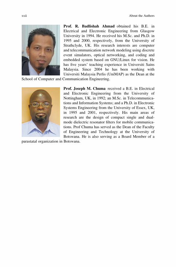
Prof. R. Badlishah Ahmad obtained his B.E. in
Electrical and Electronic Engineering from Glasgow
University in 1994. He received his M.Sc. and Ph.D. in
1995 and 2000, respectively, from the University of
Strathclyde, UK. His research interests are computer
and telecommunication network modeling using discrete
event simulators, optical networking, and coding and
embedded system based on GNU/Linux for vision. He
has five years’ teaching experience in Universiti Sains
Malaysia. Since 2004 he has been working with
Universiti Malaysia Perlis (UniMAP) as the Dean at the
School of Computer and Communication Engineering.
Prof. Joseph M. Chuma received a B.E. in Electrical
and Electronic Engineering from the University of
Nottingham, UK, in 1992; an M.Sc. in Telecommunica-
tions and Information Systems; and a Ph.D. in Electronic
Systems Engineering from the University of Essex, UK,
in 1995 and 2001, respectively. His main areas of
research are the design of compact single and dual-
mode dielectric resonator filters for mobile communica-
tions. Prof Chuma has served as the Dean of the Faculty
of Engineering and Technology at the University of
Botswana. He is also serving as a Board Member of a
parastatal organization in Botswana.
xxii About the Authors