Embed Size (px)
Citation preview
L&T Valves Limited TAMIL NADU
Report No. 8113245702-100-01
Submitted to L&T Valves Ltd.
Report by TUV India CHENNAI
Chennai: 8 June 2016
K. P. S. IYER Team Leader
V. Viswanathan
Head of Certifying Services
SAFETY INTEGRITY LEVEL (SIL) VERIFICATION FOR
HIGH INTEGRITY PRESSURE PROTECTION SYSTEM
(HIPPS)
MAY 2016

Table of Contents
SAFETY INTEGRITY LEVEL (SIL) VERIFICATION STUDIES FOR HIPPS .................................................................... 1
1 BACKGROUND AND OVERVIEW ..................................................................................................... 1
2 DESCRIPTION OF HIPPS AND ITS CONFIGURATION ........................................................................... 1
2.1 Details of the HIPPS Assembly ............................................................................................ 1
2.2 Operation logic of the HIPPS ............................................................................................... 2
TABLE 1 CHARACTERISTICS OF HIPPS ASSEMBLY .................................................................................. 3
3 VERIFICATION PROCESS ............................................................................................................... 4
3.1 Input Data ........................................................................................................................... 4
3.2 Definitions ........................................................................................................................... 4
3.3 Assumptions ........................................................................................................................ 6
3.4 Approach adopted .............................................................................................................. 6
4 RESULTS OF THE ANALYSIS ............................................................................................................ 7
5 SUMMARY AND CONCLUSION ....................................................................................................... 8
ANNEXURE A: PFDavg VALUES FOR HIPPS AND COMPONENTS ............................................................ 9
A. HIPPS Assembly ........................................................................................................................... 9
B. Sensors ....................................................................................................................................... 11
C. Final Element ............................................................................................................................. 12
Abbreviation Full Expression
FIT Failure rate In Time
HFT Hardware Fault Tolerance
PFD Probability of Failure on Demand
PFDavg Probability of Failure on Demand, Average
PST Partial Stroke Testing
SFF Safe Failure Fraction
SIF Safety Instrumented Function
SIL Safety Integrity Level
SIS Safety Instrumented System

SIL VERIFICATION REPORT NO.: 8113245702-100-01 DT. 8 JUNE 2016
1 TUV
SAFETY INTEGRITY LEVEL (SIL) VERIFICATION STUDIES FOR HIPPS
1 BACKGROUND AND OVERVIEW
L&T Valves in addition to manufacturing valves also assembles systems and products such as High-
Integrity Pressure Protection System (HIPPS) for safety applications.
HIPPS consist of pressure sensors, transmitters, logic solvers and valves used in applications for
preventing over-pressurisation in the process industry. HIPPS need to be extremely reliable and safe
as they shut off the high pressure source on demand. HIPPS typically need to meet SIL 3 or SIL 4
according to IEC 61508 / IEC 61511.
While the SIL rating for the individual components that make up the HIPPS are available, L&T
requires the SIL level of the HIPPS loop to be evaluated under IEC
(IEC 61511/61508) for each Safety Instrumented Function (SIF) executed by the loop.
The report contains the analysis and results of the verification process.
2 DESCRIPTION OF HIPPS AND ITS CONFIGURATION
HIPPS is an example of a Safety Instrumented System (SIS) applied to over pressure protection
systems. The design, assembly, operation and maintenance are covered by IEC 61508/ 61511. The
safety function of the HIPPS is to close the source of over-pressure within a predetermined time
frame with at least the same reliability as a safety relief valve.
A HIPPS is considered as a barrier between a high-pressure and a low-pressure section of an
installation and consists of several individual components functioning on demand. The HIPPS is a
complete functional loop consisting of:
a) Sensors, (or initiators) that detect the high pressure/ low pressure scenario
b) A logic solver that processes the input from the sensors to an output to the final element
c) Final elements (valve, actuator and solenoid) that actually perform the corrective action in
the field by bringing the process to a safe state.
The components of the HIPPS integrated by L&T Valves consist of Pressure Transmitter, Logic solver,
Trunnion Mounted Ball Valve (TMBV), Hydraulic actuator with solenoid valve/ pilot valve
2.1 Details of the HIPPS Assembly
The HIPPS design configuration and architecture is given in Fig 1

SIL VERIFICATION REPORT NO.: 8113245702-100-01 DT. 8 JUNE 2016
2 TUV
Fig 1 P&ID of the HIPPS
The HIPPS consists of the following major components:
1. Shutdown valves of 12” size with hydraulic actuator and all required accessories
2. Pressure Transmitters (in 2oo3/1oo2 configuration) along with Interlocking manifold
3. Solid State Logic solver in HIPPS cabinet, to be installed at Gas Gathering Station (GGS)
Instrument Equipment Room
4. Field mounted local control panel
5. Fiber Optic Link in HIPPS cabinet for connecting the HIPPS cabinet to the Fiber optic patch
panel located in Gas Gathering Station (GGS) Instrument Equipment Room for monitoring
and storage of all analysis data from Gas Processing Plant (GPP).
The control panel and fiber optic link are considered to be non-interfering components as their
functions are non-safety related and do not impact the safety function of the HIPPS.
2.2 Operation logic of the HIPPS
The System is an integrated package located at upstream of the pig launcher of the Gas Gathering
Station (GGS). HIPPS process trip inputs will be from the three pressure transmitters in 2oo3
configuration. If the pressure rises above the predefined set point, the HIPPS 2oo3 voting function
(comparator module for 3 pressure transmitters) closes both the HIPPS TMBV valves.
SIL VERIFICATION REPORT NO.: 8113245702-100-01 DT. 8 JUNE 2016
3 TUV
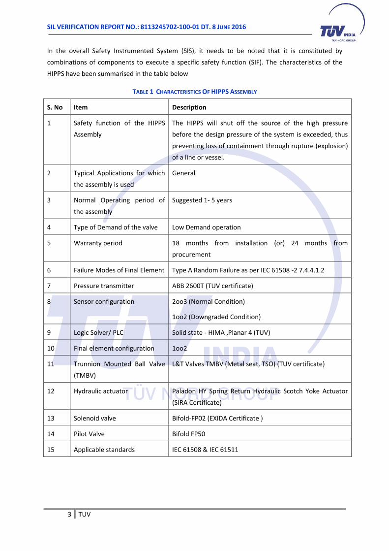
In the overall Safety Instrumented System (SIS), it needs to be noted that it is constituted by
combinations of components to execute a specific safety function (SIF). The characteristics of the
HIPPS have been summarised in the table below
TABLE 1 CHARACTERISTICS OF HIPPS ASSEMBLY
S. No Item Description
1 Safety function of the HIPPS
Assembly
The HIPPS will shut off the source of the high pressure
before the design pressure of the system is exceeded, thus
preventing loss of containment through rupture (explosion)
of a line or vessel.
2 Typical Applications for which
the assembly is used
General
3 Normal Operating period of
the assembly
Suggested 1- 5 years
4 Type of Demand of the valve Low Demand operation
5 Warranty period 18 months from installation (or) 24 months from
procurement
6 Failure Modes of Final Element Type A Random Failure as per IEC 61508 -2 7.4.4.1.2
7 Pressure transmitter ABB 2600T (TUV certificate)
8 Sensor configuration 2oo3 (Normal Condition)
1oo2 (Downgraded Condition)
9 Logic Solver/ PLC Solid state - HIMA ,Planar 4 (TUV)
10 Final element configuration 1oo2
11 Trunnion Mounted Ball Valve
(TMBV)
L&T Valves TMBV (Metal seat, TSO) (TUV certificate)
12 Hydraulic actuator Paladon HY Spring Return Hydraulic Scotch Yoke Actuator
(SIRA Certificate)
13 Solenoid valve Bifold-FP02 (EXIDA Certificate )
14 Pilot Valve Bifold FP50
15 Applicable standards IEC 61508 & IEC 61511

SIL VERIFICATION REPORT NO.: 8113245702-100-01 DT. 8 JUNE 2016
4 TUV
3 VERIFICATION PROCESS
The sub components that form the SIS loop have been certified individually for their SIL
compatibility. The overall objective of the verification study was to calculate the average Probability
of Dangerous Failure (PFDavg) and the architectural constraints that dictate the achievable SIL rating
for the SIS loop.
3.1 Input Data
The SIL Verification study has been undertaken for the given configuration. The manufacturers of the
individual components have provided SIL class certificates for each equipment.
The following information provided by the company was used in the study.
TABLE 2 CERTIFICATES/REFERENCE DOCUMENTS USED FOR THE STUDY
Component Make Model Certificate №.
Pressure Transmitter ABB 2600T SEBS-A. 164727/14, V1.0
Logic Solver HIMA PLANAR 4 – U 98 06 19183 027
Trunnion Mounted Ball Valve L&T Valves Metal seat, TSO 8112375050-100-01
Actuator Paladon
systems
Spring Return HYS
Hydraulic Scotch Yoke
Sira FSP 13007/01
Solenoid Valve Bifold FP02 BIF 1107001C001
Pilot Valve Bifold Bifold FP50 SM. FP50 Rev 10
Based on the certificates issued for the individual components, the quantitative analysis of the sub-
components in the HIPPS assembly was performed. This analysis has revealed the overall SIL Rating
for the entire Safety Instrumented System.
This report addresses the verification of the loop at the design stage based on the selection of
components and configuration.
3.2 Definitions
The following definitions pertain to the study and are taken from IEC 61508-4 c IEC:2010
Failure Rate the frequency with which an engineered system or component fails, expressed
in failures per unit of time. It is denoted by the Greek letter λ (lambda)1.
The lifetime of a population of a product consists of three periods: ‘break-in’ or
infant mortality period with a decreasing failure rate followed by a normal life
1 reliability parameter (λ(t)) of an entity (single components or systems) such that λ(t).dt is the probability of
failure of this entity within [t, t+dt] provided that it has not failed during [0, t]

SIL VERIFICATION REPORT NO.: 8113245702-100-01 DT. 8 JUNE 2016
5 TUV
period (also known as "useful life") with a low, relatively constant failure rate and
concluding with an ‘end-of-life’ or wear-out period that exhibits an increasing
failure rate.
FIT Failure In Time – (1x10⁻⁹ failures per hour)
Low demand mode where the safety function is only performed on demand, in order to transfer
the equipment under control into a specified safe state, and where the frequency
of demand is no greater than one per year
MTTR Mean Time To Restoration -- expected time to achieve restoration. MTTR
encompasses the time to detect the failure (a); and, the time spent before
starting the repair (b); and, the effective time to repair (c); and, the time before
the component is put back into operation (d). The start time for (b) is the end of
(a); the start time for (c) is the end of (b); the start time for (d) is the end of (c).
PFDavg average probability of dangerous failure on demand – mean unavailability (see
IEC 60050-191) of an E/E/PE safety-related system to perform the specified safety
function when a demand occurs from the equipment under control (EUC) or EUC
control system
Proof Test Periodic test performed to detect dangerous hidden failures in a safety-related
system so that, if necessary, a repair can restore the system to an “as new”
condition or as close as practical to this condition
PST Partial Stroke Test is a technique used in a control system to allow the user to test
a percentage of the possible failure modes of an element/ sub-system (e.g.: a
shutdown valve) without the need to physically disable/ disconnect the element/
sub-system (e.g., close the valve). PST is used to assist in determining that the
safety function will operate on demand. PST is not a replacement for the need to
fully stroke valves as proof testing is still a mandatory requirement.
RRF Risk Reduction Factor – the number of times that risk is reduced as a result of the
application of a safeguard
SIL Safety Integrity Level – discrete level (one out of a possible four), corresponding
to a range of safety integrity values, where safety integrity level 4 has the highest
level of safety integrity and safety integrity level 1 has the lowest
SFF Safe Failure Fraction – summarizes the fraction of failures, which lead to a safe
state and the fraction of failures which will be detected by diagnostic measures
and lead to a defined safety action.
Type A device A subsystem can regarded as type A when the components required to achieve
the safety function meet all of the following conditions:
a) the failure modes of all constituent components are well defined; and
SIL VERIFICATION REPORT NO.: 8113245702-100-01 DT. 8 JUNE 2016
6 TUV
b) the behaviour of the subsystem under fault conditions can be completely
determined; and
c) there is sufficient dependable failure data from field experience to show that
the claimed rates of failure for detected and undetected dangerous failures are
met.
Type B device A subsystem that does not qualify as Type A device is termed as a Type B device.
Type B devices are complex components with potentially unknown failure, when
one or more of the components required to perform a specified function is not
Type A.
3.3 Assumptions
The following assumptions were considered during the calculations of the failure rate for the system.
1. Failure rates are assumed to be constant during the usable life of the sub-components
(Break–in period failures or end of life scenarios are not taken into account)
2. Proof Tests are assumed to detect all of the faults in the system
3. A minimum proof test period of greater than 50% of the demand of the subsystem is used
for calculation of PFDavg
4. All components have been identified as Type A devices and operating under Low Demand
mode (as per IEC 61508-4 3.5.16)
5. The total number of operational hours in a single year is assumed as 8760 hrs
6. The mean time to repair/ restoration (MTTR) for each component was assumed as 24 hours.
7. Restoration is assumed to be 100% effective to restore each component to fault-less state.
8. Non-interfering components, i.e. those components which do not impact the performance
of the safety function of the system (Interaction-Free modules), are not included in the
verification calculations. For example, the Communication modules 80100/1/2, Quadruple
Fuse module 90100, Dual bypass module 90300, etc.
3.4 Approach adopted
The approach followed for the verification of the SIL rating for the HIPPS is given below
1) Estimation of the Average Probability of Failure on demand (PFDavg) for the individual
sub-systems (Initiating Device; Logic solver; Final Element) of HIPPS assembly
2) Assigning of SIL compatibility rating of the assembly under their respective
configurations.
3) Selection of proof test interval to obtain the least average probability for dangerous
failure (PFDavg) for the HIPPS assembly.

SIL VERIFICATION REPORT NO.: 8113245702-100-01 DT. 8 JUNE 2016
7 TUV
The values of Failure rate in Time (FIT) used in the calculations were collated from the certificates
issued for the individual components. In compliance with applicable portion in IEC 61508/61511 the
calculations were carried out for each design configuration within the specified assembly.
4 RESULTS OF THE ANALYSIS
The process of verification was carried out and the results of the SIL compatibility study are
discussed in the following sections.
A. FIT for valve Assembly No 1
Failure rate in Time (FIT) used in the above calculations were collected from the given certified
sources. The values of failure rates have been taken from the certificates issued for the individual
components in compliance with applicable portion in IEC 61508/61511 for each unit of equipment
within the specified assembly and presented in Table 3.
TABLE 3 SUMMARY OF FIT FOR INDIVIDUAL COMPONENTS OF VALVE ASSEMBLY
(W PARTIAL STROKE TESTING)
# Component Make, Model Certificate ref. Lambda values λ (1/h) SFF
λDD λDU λSD λSU %
1 Initiator
(Pressure
Transmitter)
ABB 2600T SEBS-A.
164727/14, V1.0
4.64E-07 7.93E-08 2.51E-07 1.25E-07 91
2 Valve L&T TMBV
(Metal seat,
TSO)
TUV Report No.
8112375050-
100-01
8.74E-08 8.95E-08 1.81E-08 9.74E-10 54
3 Actuator Paladon
systems
Sira FSP
13007/01
0 4.95E-08 0 8.86E-08 64
4 Solenoid Valve Bifold FP02 Exida BIF
1107001C001
1.43E-07 2.00E-09 0 3.36E-07 99
5 Pilot Valve Bifold FP50 SM. FP50 Rev 10 2.04E-07 3.00E-09 0 3.39E-07 99
B. PFDavg and Risk Reduction Factor
The values for average probability of dangerous failure (PFDavg) and Risk Reduction Factor dictate the
claimed SIL level for the sub-system. These indicate the actual amount of protection and risk
reduction that the HIPPS can offer to the end user’s process.
The average probability of dangerous failures (PFDavg) have been calculated as per following cases of
end use/application

SIL VERIFICATION REPORT NO.: 8113245702-100-01 DT. 8 JUNE 2016
8 TUV
1) SIF 1: If the pressure rises above the predefined set point, the HIPPS 2oo3 voting function
(comparator module for 3 pressure transmitters) closes both the HIPPS valves. (Downgraded
mode is also possible)
2) ADDITIONAL FUNCTION: If the pressure falls below the predefined set point (From
downstream PT 1oo1 configuration), the HIPPS shall close both the HIPPS valves.
The case for downgraded condition of operation of the HIPPS was also considered. Downgraded
condition refers to the change of the voting logic of the sensor element or initiating device from
2oo3 voting to 1oo2 under certain predefined circumstances. The conditions for switching to
downgraded mode for the sensors are as follows:
1) Any one Pressure transmitter is isolated with Unique Key in Manifold block
2) Line monitoring fault for a HIPPS transmitter is detected
3) Failure of input analogue card
The achieved PFDavg and Risk Reduction Factor (RRF) are reported in the table 4.
TABLE 4 SUMMARY OF SIL RATINGS FOR HIPPS ASSEMBLY
Safety Integrity
Function
Application Average
Probability of
Dangerous
Failure,
PFDavg
Testing Interval
Required,
TI
Partial Stroke
Test Interval
Compatible
SIL
Risk Reduction
Factor (RRF)
SIF 1 Fail to
Close on
Demand
2.94E-04 1 year
1 month SIL 3
3.40E+03
SIF 1
(Downgraded)
Fail to
Close on
Demand
2.87E-04 1 year 1 month
SIL 3 3.49E+03
ADDITIONAL
FUNCTION
Fail to
Close on
Demand
8.17E-04 1 year 1 month SIL 3 1.24E+03
5 SUMMARY AND CONCLUSION
The current report contains the results of the verification of the SIL class of L&T’s HIPPS SIS loop as
per IEC requirements for subsystem.
The main results of the verification process are summarized below:
SIFs for the given conditions comply with SIL3 as per Architectural constraints and PFDavg
SIL VERIFICATION REPORT NO.: 8113245702-100-01 DT. 8 JUNE 2016
9 TUV
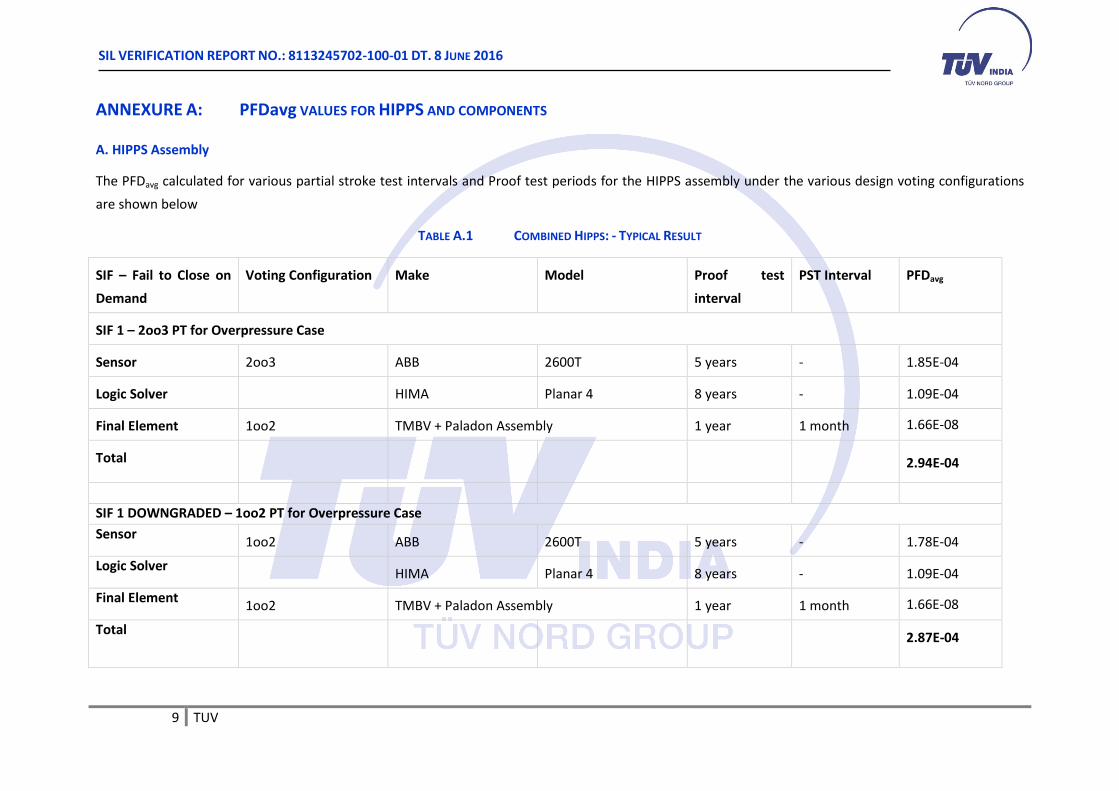
ANNEXURE A: PFDavg VALUES FOR HIPPS AND COMPONENTS
A. HIPPS Assembly
The PFDavg calculated for various partial stroke test intervals and Proof test periods for the HIPPS assembly under the various design voting configurations
are shown below
TABLE A.1 COMBINED HIPPS: - TYPICAL RESULT
SIF – Fail to Close on
Demand
Voting Configuration Make Model Proof test
interval
PST Interval PFDavg
SIF 1 – 2oo3 PT for Overpressure Case
Sensor 2oo3 ABB 2600T 5 years - 1.85E-04
Logic Solver HIMA Planar 4 8 years - 1.09E-04
Final Element 1oo2 TMBV + Paladon Assembly 1 year 1 month 1.66E-08
Total 2.94E-04
SIF 1 DOWNGRADED – 1oo2 PT for Overpressure Case
Sensor 1oo2 ABB 2600T 5 years - 1.78E-04
Logic Solver HIMA Planar 4 8 years - 1.09E-04
Final Element 1oo2 TMBV + Paladon Assembly 1 year 1 month 1.66E-08
Total 2.87E-04
SIL VERIFICATION REPORT NO.: 8113245702-100-01 DT. 8 JUNE 2016
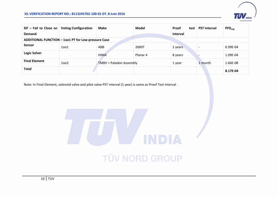
10 TUV
SIF – Fail to Close on
Demand
Voting Configuration Make Model Proof test
interval
PST Interval PFDavg
ADDITIONAL FUNCTION – 1oo1 PT for Low pressure Case
Sensor 1oo1 ABB 2600T 2 years - 6.99E-04
Logic Solver HIMA Planar 4 8 years - 1.09E-04
Final Element 1oo2 TMBV + Paladon Assembly 1 year 1 month 1.66E-08
Total 8.17E-04
Note: In Final Element, solenoid valve and pilot valve PST interval (1 year) is same as Proof Test interval .
SIL VERIFICATION REPORT NO.: 8113245702-100-01 DT. 8 JUNE 2016
11 TUV
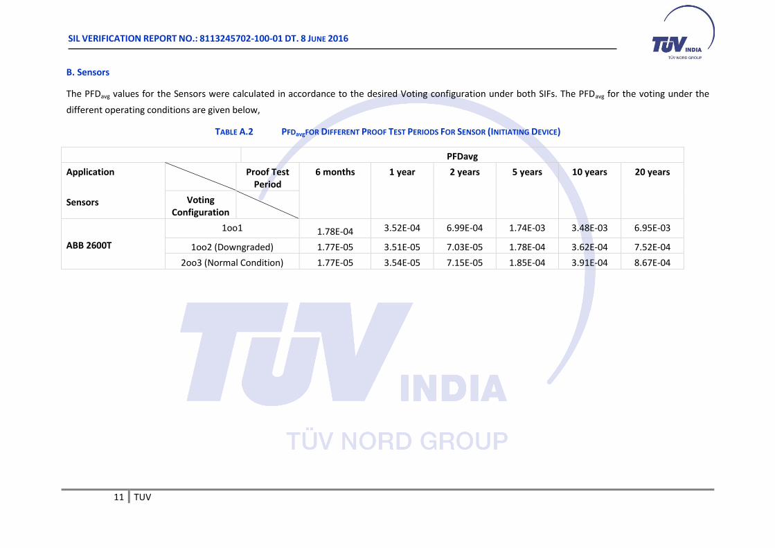
B. Sensors
The PFDavg values for the Sensors were calculated in accordance to the desired Voting configuration under both SIFs. The PFDavg for the voting under the
different operating conditions are given below,
TABLE A.2 PFDavgFOR DIFFERENT PROOF TEST PERIODS FOR SENSOR (INITIATING DEVICE)
PFDavg
Application
Sensors
Proof Test Period
6 months 1 year 2 years 5 years 10 years 20 years
Voting Configuration
ABB 2600T
1oo1 1.78E-04 3.52E-04 6.99E-04 1.74E-03 3.48E-03 6.95E-03
1oo2 (Downgraded) 1.77E-05 3.51E-05 7.03E-05 1.78E-04 3.62E-04 7.52E-04
2oo3 (Normal Condition) 1.77E-05 3.54E-05 7.15E-05 1.85E-04 3.91E-04 8.67E-04

SIL VERIFICATION REPORT NO.: 8113245702-100-01 DT. 8 JUNE 2016
12 TUV
C. Final Element
The PFDavg calculated for various partial stroke test intervals and Proof test periods for the Final element under 1oo2 voting condition are shown below,
TABLE A.3 PFDavgFOR DIFFERENT PROOF TEST PERIODS AND PARTIAL STROKE TEST FREQUENCY FOR FINAL ELEMENT
PFDavg
Application
1oo2 w/ PST
Proof Test Period
6 months 1 year 2 years
5 years 10 years 20 years
PST Interval
Metal Seat 1 month 6.79E-09 1.66E-08 4.94E-08 2.52E-07 9.37E-07 3.61E-06
2 months 1.28E-08 2.55E-08 6.40E-08 2.84E-07 9.97E-07 3.73E-06
3 months 2.07E-08 3.63E-08 8.05E-08 3.17E-07 1.06E-06 3.85E-06
6 months - 7.99E-08 1.41E-07 4.30E-07 1.26E-06 4.22E-06
9 months - - 2.19E-07 5.59E-07 1.47E-06 4.61E-06
12 months - - 3.14E-07 7.05E-07 1.71E-06 5.01E-06