Embed Size (px)
Citation preview

LSW Reference Manual
For the Lantronix LSW8F-S Fast Ethernet Switch

Contents
1 Introduction 1-1
1.1 Features............................................................................................................................................ 1-11.1.1 Connectivity Features .................................................................................................. 1-11.1.2 Automatic Switching Features.................................................................................... 1-11.1.3 Management Options................................................................................................... 1-21.1.4 Management Features .................................................................................................. 1-21.1.5 Additional Features ...................................................................................................... 1-3
1.2 Concepts .......................................................................................................................................... 1-31.2.1 Ethernet .......................................................................................................................... 1-31.2.2 Fast Ethernet .................................................................................................................. 1-51.2.3 Switching........................................................................................................................ 1-6
2 EZWebCon Management 2-1
2.1 Obtaining EZWebCon Software................................................................................................... 2-12.2 Installing and Running EZWebCon Software ........................................................................... 2-1
2.2.1 Windows 95/NT........................................................................................................... 2-22.2.2 Solaris/SPARC.............................................................................................................. 2-22.2.3 Java.................................................................................................................................. 2-3
2.3 Using EZWebCon........................................................................................................................... 2-42.3.1 Navigating EZWebCon................................................................................................ 2-52.3.2 Device Selection ............................................................................................................ 2-62.3.3 SNMP Communities Screen ........................................................................................ 2-62.3.4 EZWebCon Device Main Menu Screen ..................................................................... 2-7
3 Telnet/Serial Login Management 3-1
3.1 Assigning an IP Address............................................................................................................... 3-13.1.1 Via Telnet ....................................................................................................................... 3-13.1.2 Via the Serial Port ......................................................................................................... 3-1
i

3.2 Navigating In Telnet/Serial Login Screens ................................................................................ 3-33.2.1 Terminal Type Selection Screen.................................................................................. 3-33.2.2 Main Menu Screen ........................................................................................................ 3-43.2.3 The Network Configuration Screen ........................................................................... 3-53.2.4 About Screen ................................................................................................................. 3-73.2.5 Quit Current Session .................................................................................................... 3-7
4 SNMP 4-1
4.1 Overview ......................................................................................................................................... 4-14.2 Configuration.................................................................................................................................. 4-1
4.2.1 Telnet/Serial Configuration........................................................................................ 4-24.2.2 EZWebCon Configuration........................................................................................... 4-5
5 RMON 5-1
5.1 RMON Groups ............................................................................................................................... 5-15.2 RMON Set-up ................................................................................................................................. 5-15.3 Using RMON .................................................................................................................................. 5-2
5.3.1 Using EZWebCon to Access RMON.......................................................................... 5-25.3.2 Using HP OpenView for Windows to access RMON ........................................... 5-155.3.3 Using SNMPc to access RMON ................................................................................ 5-155.3.4 History Group ............................................................................................................. 5-17
6 MIBS 6-1
7 Spanning Tree 7-1
7.1 Configuration.................................................................................................................................. 7-27.1.1 Telnet/Serial Configuration........................................................................................ 7-27.1.2 EZWebCon Configuration........................................................................................... 7-3
8 VLANs 8-1
8.1 Telnet/Serial Configuration ......................................................................................................... 8-18.2 EZWebCon Configuration ............................................................................................................ 8-2
9 Port Configuration 9-1
9.1 Telnet/Serial Port Configuration................................................................................................. 9-19.2 EZWebCon Port Configuration.................................................................................................... 9-2
10 Statistics 10-1
ii

A Technical Support A-1
B Troubleshooting B-1
C Updating Software C-1
Index i
iii


1
Introduction
1.1 Features .............................................................................................................................. 1-1
1.1.1 Connectivity Features.................................................................................. 1-1
1.1.2 Automatic Switching Features ................................................................... 1-1
1.1.3 Management Options .................................................................................. 1-2
1.1.4 Management Features ................................................................................. 1-2
1.1.5 Additional Features ..................................................................................... 1-3
1.2 Concepts ............................................................................................................................. 1-3
1.2.1 Ethernet ......................................................................................................... 1-3
1.2.2 Fast Ethernet ................................................................................................. 1-5
1.2.3 Switching....................................................................................................... 1-6


Introduction Features
1 - 1
1 - IntroductionThe LSW8F-S Ethernet Switch provides the user with state-of-the-art 10Mbps Ethernet or 100Mbps Fast Ethernet switching technology. The LSW8F-S allows the user to segment a network into 10Mbps Ethernet segments or 100Mbps Fast Ethernet segments.
This chapter outlines LSW8F-S features and explains important concepts related to operating the LSW8F-S.
1.1 Features
1.1.1 Connectivity Features
1.1.1.1 Eight Fast Ethernet Ports
The LSW8F-S has eight RJ45 10/100 Fast Ethernet Ports, and allows the user to choose between Ethernet and Fast Ethernet for each network segment. Each port supports a full segment length allowing the maximum number of repeater hops or the maximum number of allowable nodes to be attached. All ports can support UTP or STP cable.
1.1.1.2 A 1 Gbps Switching Bus
The LSW8F-S bus is capable of handling throughput of up to 1 Gigabit across its ports. The LSW8F-S is tested to both internal and external specifications for throughput verification.
1.1.1.3 MDI/MDI-X Support
Port 1 features an MDI/MDI-X option push button to allow uplink to another device without changing Ethernet cables. The MDI option is selected when connecting to another switch or a hub, while selecting the MDI-X option allows Port 1 to function just as the other seven ports.
1.1.2 Automatic Switching Features
The managed LSW8F-S Fast Ethernet Switch has a number of automatic switching functions that require no configuration or management. These features make the LSW8F-S a stand-alone, plug-and-play switching solution.
1.1.2.1 Self-learning
Once powered on, the LSW8F-S evaluates all Ethernet/Fast Ethernet packet traffic. It then main-tains a table listing MAC addresses, and the switch segments on which those addresses reside. This function is automatic and continuous for the life of the LSW8F-S.
The LSW8F-S forwards (sends) or filters (drops) packets based upon their source and destination addresses, and the segments on which those addresses reside. Broadcasts are sent to all ports.
The optional filters and VLAN support, provided by the LSW8F-S software, work over and above this basic switch functionality.
1.1.2.2 Bad Packet Filtering
The LSW8F-S is a store-and-forward switch, which examines each and every packet in its entirety. This method allows the LSW8F-S to identify, and subsequently filter out, bad packets. By remov-ing bad packets, the LSW8F-S improves network performance. The LSW8F-S also provides relief from potentially catastrophic conditions caused by a failure on a single segment. Cut-through switches, and most hubs, do not support this function.

Features Introduction
1.1.2.3 Auto-negotiation of Speed and Duplex
When an Ethernet or Fast Ethernet segment is attached to the LSW8F-S, the port will automatically negotiate the speed and duplex mode of the port according to the IEEE 802.3u clause 28 rules. The hierarchy for this negotiation is as follows:
1. 100BASE-T full duplex
2. 100BASE-T half duplex
3. 10BASE-T full duplex
4. 10BASE-T half duplex
If the device on the other end of the segment does not support auto-negotiation, the connection will default to half duplex. The LSW8F-S also has the ability to autosense the speed of a connection without the use of auto-negotiation, and allow the user to manually set both speed and duplex for individual ports (see Chapter 9, Port Configuration). This feature enhances compatibility with older NICs and other devices that do not support auto-negotiation.
1.1.3 Management Options
The LSW8F-S can be managed via EZWebCon and serial logins. Support for the SNMP, MIBs, RMON, the Spanning Tree Algorithm, VLANs, and packet filters further enhances management functionality.
1.1.3.1 EZWebCon
EZWebCon is a Java application that allows point-and-click configuration and management of the LSW8F-S.
NOTE: As web browsers begin to support Java, EZWebCon will be a web browser based interface.m Such operation is not recommended at this time.
1.1.3.2 Serial Logins
The LSW8F-S supports logins via the serial port or (once an IP address has been configured in the unit) logins via Telnet. Logins use a menu-driven interface that requires an access password in order to make device changes.
NOTE: An RJ45 cable kit is included with every unit for management via the RJ45 serial management port.
1.1.4 Management Features
1.1.4.1 SNMP
The LSW8F-S supports SNMP, the Simple Network Management Protocol (specifically RFCs 1155 through 1157). This feature allows any device compatible with SNMP (Version 1) to manage the LSW8F-S.
1.1.4.2 MIBs
The following MIBs (Management Information Bases) are supported: RMON, MIB2, Bridge MIB and Lantronix Enterprise MIB.
Four groups of RMON (Remote Monitoring MIB) are supported by the LSW8F-S: Statistics, His-tory, Alarms and Events.
1 - 2

Introduction Concepts
1.1.4.3 Spanning Tree
The LSW8F-S supports the Spanning Tree Algorithm (IEEE 802.1d). When this feature is enabled (the default), the LSW8F-S will share addressing information with other participating devices, ensuring singular pathways between all network nodes.
1.1.4.4 VLANs
The LSW8F-S allows the user to create port-based VLANs (Virtual Large Area Networks). VLANs allow the user to group nodes together, irrespective of their physical locations on the switched segments. When a port is configured as part of a VLAN, that port will see all traffic between all ports associated with that VLAN.
1.1.4.5 Filters
The user can create filters based upon IP source addresses or Ethernet (MAC) addresses to selec-tively block packet traffic. Such filters can be used to enhance security or to increase performance.
1.1.4.6 Informational LEDs
LEDs, located prominently on the LSW8F-S, provide instant information on the state of a segment including good link/duplex, speed, collisions, and received data.
1.1.5 Additional Features
1.1.5.1 Support for 8192 Addresses
The LSW8F-S can support up to 8,192 MAC addresses in its table to ensure that it will never over-run the table, even in the largest network applications.
1.1.5.2 Free Technical Support
Lantronix provides free technical support for the lifetime of the LSW8F-S. Support is available by telephone, web-site connection or email. See Appendix A for more information.
1.1.5.3 Five-year Limited Warranty
Lantronix backs all current products with a 5-year limited warranty. Refer to the Warranty page in the back of your Installation Guide for more information.
1.2 Concepts
1.2.1 Ethernet
Ethernet is the most popular physical layer LAN technology in use today. Ethernet is popular because it strikes a good balance between speed, cost, and ease of installation. These strong points, combined with wide acceptance in the computer marketplace and the ability to support virtually all popular network protocols, make Ethernet an ideal networking technology for most computer users today.
NOTE: Other LAN types include Token Ring, Fast Ethernet, Fiber Distributed Data Inter-face (FDDI), Asynchronous Transfer Mode (ATM), and LocalTalk.
The Ethernet standard is defined by the Institute for Electrical and Electronic Engineers (IEEE) as IEEE Standard 802.3. This standard defines the rules for configuring an Ethernet, as well as speci-fies how elements in an Ethernet network interact with one another. By adhering to the IEEE stan-dard, network equipment and network protocols will interoperate efficiently.
1 - 3

Concepts Introduction
Ethernet has design rules that must be followed, in order to function correctly. The maximum number of nodes, the number of repeaters, and maximum segment distances are defined by the electrical and mechanical design properties of each type of Ethernet media. Although electrical signals on the media travel near the speed of light, it still takes a finite time for the signal to travel from one end of an Ethernet to another. The Ethernet standard assumes it will take roughly 50 microseconds for a signal to reach its destination.
Travel time of an impulse on the Ethernet network is important because Ethernet is a shared-bus design. Since only one node can transmit at a time, all other nodes must wait. If two nodes trans-mit at once, a collision occurs.
Ethernet operates on a principle known as CSMA/CD (Carrier Sense Multiple Access / Collision Detect). If a node detects another node transmitting, it will not transmit. The speed of an impulse is critical to this timing, since a node waiting to transmit knows it must wait a minimum of 50 µs for an existing impulse to reach all ends of the medium. Once this time period elapses, the node wishing to transmit can try again. Should any node notice that another node is transmitting, dur-ing or after transmission is initiated, it must “jam” its transmission to invalidate the data, back off and attempt to send later. While all of this sounds like it takes a long time, recall that the intervals are microseconds. A lot can happen on the Ethernet in one second!
The speed and impedance of the Ethernet media affects network size and transmission distance. The following are calculated maximum distances and nodes supported:
To expand on these distance restrictions, the IEEE 802.3 specification allows for the use of repeat-ers. Repeaters are devices that amplify an existing Ethernet signal and send it out single or multi-ple ports. By boosting the signal, repeaters allow the network to extend beyond the single cable limits shown above.
There are limits to this expansion. First, Ethernet is subject to the “5-4-3” rule of repeater place-ment. Based on the electrical properties of the re-transmissions and overall end-to-end transmit times, an Ethernet network can have only five segments connected via repeaters. Second, an Ethernet network can use only four repeaters in the overall configuration. Finally, of the five seg-ments, only three can have users (end nodes) attached to them. The other two must be inter-repeater links, strictly between repeaters. If the design of the network violates the rules of repeater or node placement, collisions, bad packets, and other timing problems will result in poor network performance.
Table 1-1: Ethernet Media Specifications
Network TypeMaximum. Nodes Per Segment
Maximum. DistancePer Segment
10BASE5 100 500 m
10BASE2 30 185 m
10BASE-T 2 100 m
10BASE-FL 2 2000 m
1 - 4

Introduction Concepts
1.2.2 Fast Ethernet
Ethernet provides a well established standard, achieving a very high level of vendor interoperabil-ity for data transmission at a rate of 10 Megabits per second (Mbps). For Ethernet networks that need higher transmission speeds, the Fast Ethernet standard (IEEE 802.3u) was established. This standard raised the Ethernet speed limit from 10 Mbps to 100 Mbps, with only minimal changes to the existing cable structure.
There are three types of Fast Ethernet: 100BASE-TX for use with level 5 UTP cable; 100BASE-FX for use with fiber-optic cable; and 100BASE-T4 which utilizes an extra two wires for use with level 3 UTP cable. In comparison, standard 10 Mbps Ethernet will run on level 3 or above UTP cable.
Additionally, several vendors developed a competing standard called 100VG-AnyLAN, but this standard received only mild reception in the IS community. This discussion will focus only on the IEEE 802.3u specification.
The 100BASE-TX standard has become the most popular, due to its compatibility with the 10BASE-T Ethernet standard. Both standards utilize the same Ethernet frame design. The primary difference between the two standards is the signal timing; 100BASE-TX is simply 10 times faster.
The difference between normal Ethernet and Fast Ethernet is the media. Fast Ethernet is specified to run over UTP (Category 5 and above) cable or fiber optic cable. This means that the overall dis-tance possible with copper-based, Fast Ethernet is limited versus coaxial media, specified for dis-tances up to 500 meters for standard 10 Mbps Ethernet.
Fast Ethernet allows for the use of repeaters, in a manner similar to 10 Mbps Ethernet. Since Fast Ethernet uses UTP cable, and the minimum packet size takes less time to transmit than regular Ethernet, UTP repeater (hub) rules are more strict. The length of the network links and the stan-dard allow fewer repeaters.
In Fast Ethernet networks, there are two classes of repeaters. Class I repeaters have a latency of 0.7 microseconds or less, and are limited to one repeater per network. Class II repeaters have a latency of 0.46 microseconds or less, and are limited to two repeaters per network. The following are the distance (diameter) characteristics for these types of Fast Ethernet repeater combinations:
For the network manager, the incorporation of Fast Ethernet into an existing configuration pre-sents a number of decisions. Each site in the network must determine the number of users that really need the higher throughput. It must also be determined which segments of the backbone need to be reconfigured specifically for 100BASE-T. The necessary hardware must be chosen to connect the 100BASE-T segments with existing 10BASE-T segments. The abundance of compo-nents such as 10/100 NICs and 100 Mbps hubs makes these decisions easier.
Table 1-2: Media/Repeater Combinations
Fast Ethernet Copper Fiber
No repeaters 100 m 412 m*
One Class I repeater 200 m 272 m
One Class II repeater 200 m 272 m
Two Class II repeaters 205 m 228 m
(*Full Duplex Mode 2 km)
1 - 5

Concepts Introduction
1 - 6
Since all users on a shared network are competitors for the Ethernet bus, as more users are added to the network or as applications requiring more data are added, performance deteriorates. On a moderately loaded 10 Mbps Ethernet network with 30-50 users, a throughput of 2.5 Mbps may be sustained, after accounting for packet overhead, inter-packet gaps, and collisions. Increasing the number of users (and therefore packet transmissions) increases potential for collisions.
Collisions occur when two or more nodes attempt to send information at the same time. When they realize a collision has occurred, each node backs off for a random time before attempting another transmission. With shared Ethernet, the likelihood of collisions increases as more nodes are added to the shared collision domain of the shared Ethernet. The same conditions can occur on Fast Ethernet networks. If a single server or uplink is forced to support a large number of users in a shared network topology, bandwidth will be sacrificed as contention increases.
With Fast Ethernet, however, the additional problem of scalability probably outweighs the throughput issue. Since there can only be one or at most two repeated segments on the LAN, how can a Fast Ethernet network be expanded?
1.2.3 Switching
The solution to the issues of throughput in shared networks, and the scalability of Fast Ethernet networks, lies in switching. When added to the network, Ethernet switches provide a number of enhancements over shared networks. The foremost enhancement is the ability to divide networks into smaller and faster segments. Ethernet switches examine each packet, determine where that packet is destined, then forward that packet to only those ports to which the packet needs to go. Modern switches are able to perform all these tasks at wire speed, that is, without adding delay.
Aside from deciding when to forward or filter the packet, Ethernet switches also completely regenerate the Ethernet packet. This regeneration and re-timing of the packet allows each port on a switch to be treated as a complete Ethernet segment, capable of supporting the full length of the cabling along with all of the repeater restrictions.
Additionally, bad packets are identified by Ethernet switches and immediately dropped from any future transmission. This “cleansing” activity keeps problems isolated to a single segment, and keeps them from disrupting other network activity. This aspect of switching is critical in a network environment where hardware failures are to be anticipated.
Ethernet, and Fast Ethernet switching, has it roots in older Ethernet bridges. Originally designed to allow different types of media to coexist or to transmit network packets over wide distances, bridges read whole Ethernet packets, converted them to whatever format was necessary to run on the other side of the bridge, and forwarded the information on to the other side. Bridges were used within campuses, as links via leased lines to other remote networks and, in some cases, as links to other types of networks (for example, Token Ring).
As network managers began to understand how bridges worked, it became clear that the normal operation of the device provided numerous benefits, if the device were used within the LAN itself. Bridges were smart, and only forwarded packets that needed to be sent to the other side. Since the bridge was looking at the whole packet, bad packets could be dropped. Perhaps more importantly, each segment coming from a bridge was a full Ethernet segment where the full repeater rules could be applied.
Originally, bridges were slow. Primarily software devices, bridges were not able to support wire-speed transfers between two network segments. As ASIC (Application Specific Integrated Circuit) matured, bridge speed increased. As more functions could be handled by fast hardware, wire-speed packet forwarding and filtering became possible, and bridges could support multiple ports. As vendors began calling such multi-port devices switches, the term “bridge” was relegated to two-port only devices.

Introduction Concepts
1.2.3.1 The Benefits of Switching
One function of a switch is to connect separate networks together. Switches can connect different network types (such as Ethernet and Fast Ethernet), or networks composed of a single medium. Switches map the Ethernet addresses of the nodes residing on each network segment, allowing only the necessary traffic to pass through (forwarding). When a packet is received by the switch, the switch determines the destination and source segments. If the segments are the same, the packet is dropped (filtered). If the segments are different, the packet is forwarded to the correct segment.
One of the ways to alleviate throughput problems in a network is to divide traffic by segmenting it with a switch. Replacing an 8-port hub with an 8-port switch means that instead of one network being shared by all users, there will be eight networks connected to each other by a smart, wire-speed device. Wire speed, as used here, means that packet traffic moves without significant delay between segments.
Figure 1-1: Hub Versus Switch
In the above diagram, the hub connects all of the users in a shared network. All users are essen-tially competing for a spot on the same wire. In the switched environment, users on separate seg-ments see only the necessary traffic for that segment; the result is less contention, fewer packets, and increased speed. If a packet must be sent to another segment, the switch forwards that packet without delay. The users on both segments are unaware of the transaction.
Users on a 10 Mbps shared hub must compete for bandwidth. Assuming each user has the same transmission requirements, expected throughput for each user will be 1/x of the total bandwidth. If ten nodes are on the network, each gets 1 Mbps of bandwidth. Unfortunately, Ethernet does not normally run at a utilization rate of 10 Megabits. There are many estimates of maximum effective utilization, but assuming a frequently mentioned 37% effective throughput, our 10 users are now splitting 3.7 Megabits of bandwidth 10 ways (each gets 370K). Realizing they will not use a proto-col that maximizes packet sizes and data passed, we can assume a further reduction to 30%, so now each user each has only 250K of effective bandwidth.
In a switched network environment, each user has his own segment. Since each segment supports a full 10 Mbps of bandwidth, each user gets 10 Megabits. Node A sends a packet to node B. The packet reaches the switch on port 1, and it is evaluated and forwarded to the segment on port 2 at wire speed. When node B receives the packet, it sends back a packet, with virtually no contention on the Ethernet segment, to which the node is attached. Each switched segment, with dedicated or limited users, is able to get higher throughput than a shared network. For example, an 8-port switch can support eight Ethernets, each running at a full 10 Mbps. Another option is to dedicate one or more of these switched ports to a high traffic device such as a file server.
HUB
A
E
G
B
C
D
H
F to C
SWITCH
A
E
G
B
C
D
H
F to C
Shared
Switched
1 - 7

Concepts Introduction
Multimedia and video applications demand as much as 1.5 Mbps of continuous bandwidth. It would be difficult for a single user to get this bandwidth as a share of an average 10 Mbps net-work. Since video will look disjointed if the data rate is not sustained, the network manager must provide greater throughput to support such applications.
Full duplex is another method to increase bandwidth to dedicated workstations or servers. To use full duplex, special network interface cards are used in the server or workstation, and the switch must support full duplex operation. Full duplex doubles the bandwidth on a link, providing 20 Mbps for Ethernet and 200 Mbps for Fast Ethernet.
Implementing Fast Ethernet to increase performance is the next logical step. Higher traffic devices are connected to switches, or each other, via 100 Mbps Fast Ethernet, providing a tremendous amount of bandwidth. Many switches are designed with this in mind, and have Fast Ethernet uplinks for connection to a file server or other switches. Eventually, Fast Ethernet can be deployed at the desk top by equipping all computers with Fast Ethernet network interface cards and using Fast Ethernet switches and repeaters. With an understanding of the underlying technologies and products used in Ethernet networks, we can discuss some popular, real world applications.
When conditions require more distance, or an increase in the number of nodes/repeaters, a switch can be used to connect networks together. This device joins two separate networks, allowing the network design criteria to be restarted. With switches, network designers can build large networks that function well. Each network connected via one of these devices is referred to as a separate col-lision domain in the overall network. The reduction in cost of bridges and switches has reduced the impact of repeater rules on network design.
1 - 8

2
EZWebCon Management
2.1 Obtaining EZWebCon Software ..................................................................................... 2-1
2.2 Installing and Running EZWebCon Software .............................................................. 2-1
2.2.1 Windows 95/NT .......................................................................................... 2-2
2.2.2 Solaris/SPARC ............................................................................................. 2-2
2.2.3 Java................................................................................................................. 2-3
2.3 Using EZWebCon ............................................................................................................. 2-4
2.3.1 Navigating EZWebCon............................................................................... 2-5
2.3.2 Device Selection............................................................................................ 2-6
2.3.3 SNMP Communities Screen ....................................................................... 2-6
2.3.4 EZWebCon Device Main Menu Screen .................................................... 2-7


EZWebCon Management Obtaining EZWebCon Software
2 - EZWebCon ManagementEZWebCon is a Lantronix management tool designed to allow the LSW8F-S to be managed from anywhere on the network. EZWebCon is a Java application that runs on any platform supporting the Java Run-time Environment (JRE) from Sun Microsystems. EZWebCon can be used to manage all LSW8F-S units on a network. It can also be used to manage all Lantronix Remote Access, Termi-nal, and Print server products.
NOTE: The MSS1 is not currently supported.
EZWebCon provides network managers with a tool to install, configure, and manage the LSW8F-S from any computer with Java 1.1. The JRE comes bundled with EZWebCon and is installed along with EZWebCon on the target system. The result is a simple installation that provides easy point-and-click operation of the application.
2.1 Obtaining EZWebCon SoftwareEZWebCon software is currently available in three different forms: Windows 95/NT (version 4.0 or newer), Solaris/SPARC (version 2.4 or newer) or any Java 1.1 virtual machine. The first two ver-sions contain Sun’s Java virtual machine, specifically for Windows 95/Windows NT or for Sun Solaris/SPARC. The third version requires a Java 1.1 virtual machine running on the target plat-form.
If you are loading the software from the Lantronix CD-ROM, navigate to the EZWebCon directory and select the appropriate file for your operating system (Win32 for Windows 95/NT, Solaris for Solaris/SPARC, or Java for Java 1.1).
If you would prefer to download the software from the Lantronix ftp site, the URLs are as follows:
Windows 95/NT: ftp://ftp.lantronix.com/pub/ezwebcon/win32/ezwebcon.exe
Solaris/SPARC: ftp://ftp.lantronix.com/pub/ezwebcon/solaris/ezwebcon.tar.Z
Java 1.1: ftp://ftp.lantronix.com/pub/ezwebcon/java/ezwebcon.zipftp://ftp.lantronix.com/pub/ezwebcon/java/ezwebcon.tar.Z
If future software releases occur after you have purchased your LSW8F-S, and you wish to upgrade your switch software, the files will be available at a designated location on the Lantronix ftp site. As always, such software upgrades are free of charge.
2.2 Installing and Running EZWebCon SoftwareThe following instructions are for installing and running EZWebCon in Windows 95/NT and Sun Solaris/SPARC environments, and on some other systems running the Java 1.1 virtual machine.
The present state of browser-based Java implementations prevents EZWebCon from functioning properly within browsers; therefore, Lantronix does not recommend the use of EZWebCon within a web browser. Once browser-based Java implementations become stable, browser-based versions of EZWebCon will be released.
2 - 1

Installing and Running EZWebCon Software EZWebCon Management
2.2.1 Windows 95/NT
From the CD-ROM:
1. Double-click on the file ezwebcon.exe.
2. Follow the standard Windows 95 installation program through the installation process.
3. Run EZWebCon by double-clicking its icon or by choosing EZWebCon from the Start Menu (Windows 95 or NT 4.0).
From the FTP site:
1. Download the file ezwebcon.exe.
2. Create a temporary directory. This makes it easy to delete the installation files after installation is finished.
3. Run ezwebcon.exe from within the temporary directory.
4. Follow the standard Windows 95 installation program to completion.
5. Run EZWebCon by double-clicking its icon or by choosing it from the Start Menu (Windows 95 or NT 4.0).
2.2.2 Solaris/SPARC
From the CD-ROM:
1. Copy the ezwebcon.tar file from the /ezwebcon/solaris directory into a tempo-rary directory.
2. Untar the file.
Figure 2-1: Untarring the EZWebCon File
There should now be a directory called ezwebcon in the current directory, and the ezwebcon.tar file may be deleted.
3. Run EZWebCon. The following example assumes you are still in the installation directory).
Figure 2-2: Running EZWebCon
NOTE: Adding the EZWebCon/bin directory to your path will enable you to run EZWeb-Con from other directories.
tar xvf ezwebcon.tar
cd EZWebCon/bin
ezwebcon
2 - 2

EZWebCon Management Installing and Running EZWebCon Software
From the FTP site:
1. Download the ezwebcon.tar.Z archive.
2. Move or copy the archive to the directory where you want to install EZWebCon. The installation process will create an ezwebcon directory in the current direc-tory.
3. Uncompress and untar the archive.
Figure 2-3: Uncompressing and Untarring the EZWebCon File
There should now be a directory called ezwebcon in the current directory, and the ezwebcon.tar file may be deleted.
4. Run EZWebCon. You can use the same syntax as used in Figure 2-2.
NOTE: Adding the EZWebCon/bin directory to your path will enable you to run EZWeb-Con from other directories.
2.2.3 Java
From the CD-ROM or the FTP site:
1. Uncompress and untar/unzip the archive into the directory where EZWebCon will be installed. Refer to the previous sections for Windows 95/NT and Solaris/SPARC for specific commands.
2. Install a Java-1.1-compatible virtual machine for your platform (see Java 1.1 Vir-tual Machines below for details).
3. Run EZWebCon from the Java virtual machine.
Figure 2-4: Running EZWebCon via Java Virtual Machine
The java program must be in your path, and the EZWebCon.class file must be in your CLASSPATH. See your virtual machine’s documentation for specific information and instructions.
2.2.3.1 Java 1.1 Virtual Machines
Java virtual machines can be downloaded from the following URLs. Java applications work cross-platform, though not yet reliably, so not all virtual machines will successfully run EZWebCon.
• SGI Irix 5.3, 6.2, 6.3, and 6.4
SGI has a Java 1.1.3 virtual machine available at:http://www.sgi.com/Products/Evaluation/5.3-6.x_jdk_3.0.1/
If the above URL fails, a new version may have been released at:http://www.sgi.com/Fun/Free_webtools.html
uncompress ezwebcon.tar.Z
tar xvf ezwebcon.tar
java EZWebCon
2 - 3

Using EZWebCon EZWebCon Management
• Sun Solaris/x86 2.5
Sun has a Java 1.1.4 virtual machine (pre-release) for Solaris 2.5/x86 at:http://www.javasoft.com/products/jdk/1.1/jre/index.html
• HP-UX 10.20
HP has a Java 1.1.2 virtual machine for HP-UX 10.20 at:http://www.hp.com/gsyinternet/hpjdk/prel112.html
• OS/2 Warp x86
IBM has an OS/2 Warp Java 1.1.1 (w/ JIT) virtual machine at:http://www.ibm.com/Java/tools/jdk.html
You must register (free) before downloading.
• AIX 4.1.3
IBM has an AIX 4.1.3 or later Java 1.1.2 (w/ JIT) virtual machine at:http://www.ibm.com/Java/tools/jdk.html
You must register (free) before downloading.
• MacOS
Apple has not publicly released their 1.1 Java implementation. MRJ 2.0 will support Java 1.1.
2.3 Using EZWebConWhen you start EZWebCon, a screen welcomes you to the program. Click on the product family containing the product to which you wish to connect.
Figure 2-5: EZWebCon Product Selection Screen
NOTE: Placing the selection arrow (or icon) on the product family will display a list of sup-ported products for that group.
2 - 4

EZWebCon Management Using EZWebCon
2.3.1 Navigating EZWebCon
Users interact with EZWebCon screens via two methods: keyboard input to specific questions and selection of activities via the command buttons on the display. Most interaction will take place using the command buttons. The following table lists the command buttons and the functions they normally provide.
Once in EZWebCon applications, such as SNMP, RMON, or Configuration, simply clicking on a parameter field will allow editing of that field. For help text, click on the Help button.
Table 2-1: EZWebCon Button Functions
Button Color Functions
Help Yellow Obtain help for current screen.
Options Grey Display a window of general EZWebCon preference settings.
Close Blue Close the window it is in.
Previous Blue Go to the previous screen (interview or web browser).
Next Blue Go to the next screen (interview or web browser).
Reload Red In the web browser, reload the current page from the source.
Cancel Red Cancel the action the current dialog will do, and closes the dialog.
OK Green Accept the action of the current dialog and close the dialog.
Menu Blue Go to the previous menu screen.
Abort Red Exit the current interview or maintenance page.
Advanced Grey Jump to an advanced page in an interview.
Yes Green Accept the statement in a dialog.
No Red Do not accept the statement in a dialog.
Select Blue Accept the currently selected item in the maintenance navigator.
Restore Red Restore settings on current maintenance page to original values.
Re-Visit Blue Interview summary page: jump back to where selected value was entered.
Finish Blue Finish. Last page of interview has Finish button instead of Next button.
2 - 5

Using EZWebCon EZWebCon Management
2 - 6
2.3.2 Device Selection
Once you have chosen a product family, you can specify the individual device to which to connect via the Unit Selection Screen, seen in Figure 2-6.
Figure 2-6: Unit Selection Screen
The Unit Selection Screen asks you to specify a particular LSW8F-S unit. An LSW8F-S can be iden-tified by its host name or IP address. EZWebCon will default to the most recently connected node if no entry is made. Once you have selected a device, click on the OK button to proceed.
2.3.3 SNMP Communities Screen
Once connected to an LSW8F-S, EZWebCon will ask you to specify the SNMP GET and SET com-munities for the device. This ensures that a unit is reachable if SNMP is going to be used.
Figure 2-7: SNMP Communities Screen
Click in either field to enter changes; if no changes are necessary, accept the default value (the ini-tial default for LSW8F-S is public) by clicking on the OK button.
2.3.3.1 SNMP Security
In order to make the switch easier to configure initially, the LSW8F-S allows SNMP connections from any host and/or community via SNMP or RMON. THis mode is called Promiscuous mode and is designed to allow easy access to the LSW8F-S during first configuration.
Once the LSW8F-S has been powered on, it is strongly recommended that the network manager configure their trusted hosts and communities immediately and then place the LSW8F-S in Secure mode. Secure mode can be enabled via serial/Telnet interface (see SNMP Security on page 3-5) or it can be set using EZWebCon (see System Configuration Screen on page 4-5). Simply change the SNMP Security Enable parameter from OFF to ON to disable Promiscuous mode for SNMP and RMON connections.

EZWebCon Management Using EZWebCon
2.3.4 EZWebCon Device Main Menu Screen
Once connected to an LSW8F-S, EZWebCon presents menu selections for various management or configuration functions. This Main Menu serves three functions:
• It is the entry point to various management and configuration option menus.
• It is the return point after aborting or terminating a specific menu.
• It is the exit point from the configuration or management of this particular device to go back to select another.
Figure 2-8: Device Main Menu Screen
You may select either Configuration or Statistics/Monitoring. Once you have made a selection, you will enter the menu sequence for that particular option. Clicking the Menu button during any part of the ensuing EZWebCon session will return you to this point (but without saving any changes). Clicking the Return button on this screen will return you to the Device Selection Screen.
2 - 7


3 Telnet/Serial Login Management
3.1 Assigning an IP Address.................................................................................................. 3-1
3.1.1 Via Telnet ...................................................................................................... 3-1
3.1.2 Via the Serial Port......................................................................................... 3-1
3.2 Navigating In Telnet/Serial Login Screens................................................................... 3-3
3.2.1 Terminal Type Selection Screen................................................................. 3-3
3.2.2 Main Menu Screen ....................................................................................... 3-4
3.2.3 The Network Configuration Screen .......................................................... 3-5
3.2.4 About Screen................................................................................................. 3-7
3.2.5 Quit Current Session ................................................................................... 3-7

Telnet/Serial Login Management Assigning an IP Address
3 - Telnet/Serial Login ManagementThis chapter discusses the Telnet and serial login capabilities of the LSW8F-S used to access man-agement information and configuration menus. After reading this chapter, you should be able to make Telnet or serial connections to the LSW8F-S, navigate through the menus and screens, and access specific feature menus. Detailed information on each management feature (for example, SNMP and filters) is contained in later chapters.
Once the LSW8F-S has successfully executed the power-up sequence, serial port connections and Telnet logins are available. Logging into the LSW8F-S serial or Telnet ports presents you with a series of menus. These menus allow you to select LSW8F-S options, and enable or disable switch features.
NOTE: Telnet logins and serial port logins use the same menu screens.
3.1 Assigning an IP Address
3.1.1 Via Telnet
Prior to making a Telnet connection to the LSW8F-S, you must assign the switch an IP address. The LSW8F-S supports the following methods for assigning an address to the device during the power-up sequence:
• DHCP
• BOOTP
• RARP
If the LSW8F-S is powered up on a network supporting any or all of these IP-based services, and if there is a device responding to its request for these services, the LSW8F-S can obtain its IP address. Consult your specific host documentation for the procedures necessary to support the above ser-vices.
3.1.2 Via the Serial Port
If none of the above services are supported on the network where the LSW8F-S is being used, the IP address for the switch can be assigned using the serial port.
Configuration of the LSW8F-S IP address from the serial console port can occur in two ways:
• Via keyboard entry during a Boot Command Mode session, or
• Via keyboard entry during a serial port login session, after the boot process is complete.
3 - 1
Assigning an IP Address Telnet/Serial Login Management
3.1.2.1 Boot Command Mode
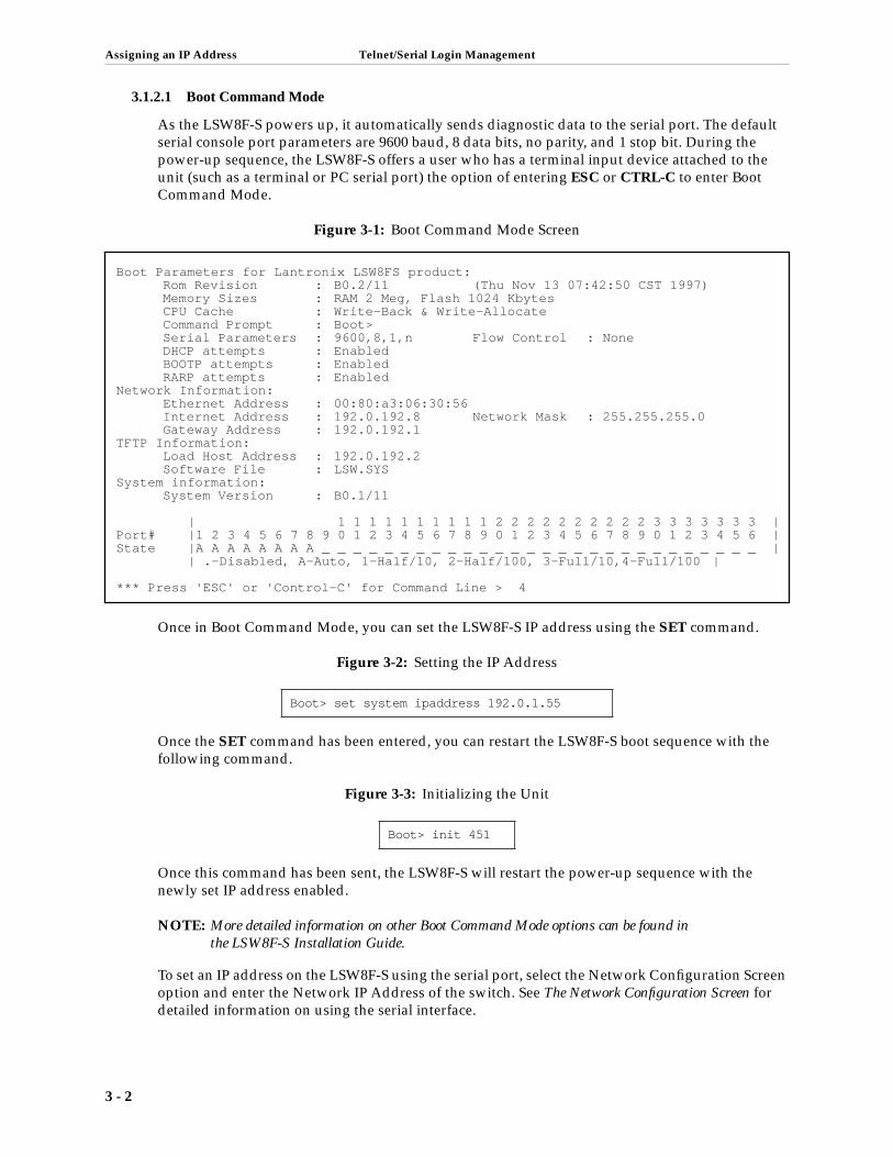
As the LSW8F-S powers up, it automatically sends diagnostic data to the serial port. The default serial console port parameters are 9600 baud, 8 data bits, no parity, and 1 stop bit. During the power-up sequence, the LSW8F-S offers a user who has a terminal input device attached to the unit (such as a terminal or PC serial port) the option of entering ESC or CTRL-C to enter Boot Command Mode.
Figure 3-1: Boot Command Mode Screen
Once in Boot Command Mode, you can set the LSW8F-S IP address using the SET command.
Figure 3-2: Setting the IP Address
Once the SET command has been entered, you can restart the LSW8F-S boot sequence with the following command.
Figure 3-3: Initializing the Unit
Once this command has been sent, the LSW8F-S will restart the power-up sequence with the newly set IP address enabled.
NOTE: More detailed information on other Boot Command Mode options can be found in the LSW8F-S Installation Guide.
To set an IP address on the LSW8F-S using the serial port, select the Network Configuration Screen option and enter the Network IP Address of the switch. See The Network Configuration Screen for detailed information on using the serial interface.
Boot> set system ipaddress 192.0.1.55
Boot> init 451
Boot Parameters for Lantronix LSW8FS product:Rom Revision : B0.2/11 (Thu Nov 13 07:42:50 CST 1997)Memory Sizes : RAM 2 Meg, Flash 1024 KbytesCPU Cache : Write-Back & Write-AllocateCommand Prompt : Boot>Serial Parameters : 9600,8,1,n Flow Control : NoneDHCP attempts : EnabledBOOTP attempts : EnabledRARP attempts : Enabled
Network Information:Ethernet Address : 00:80:a3:06:30:56Internet Address : 192.0.192.8 Network Mask : 255.255.255.0Gateway Address : 192.0.192.1
TFTP Information:Load Host Address : 192.0.192.2Software File : LSW.SYS
System information:System Version : B0.1/11
| 1 1 1 1 1 1 1 1 1 1 2 2 2 2 2 2 2 2 2 2 3 3 3 3 3 3 3 |Port# |1 2 3 4 5 6 7 8 9 0 1 2 3 4 5 6 7 8 9 0 1 2 3 4 5 6 7 8 9 0 1 2 3 4 5 6 |State |A A A A A A A A _ _ _ _ _ _ _ _ _ _ _ _ _ _ _ _ _ _ _ _ _ _ _ _ _ _ _ _ | | .-Disabled, A-Auto, 1-Half/10, 2-Half/100, 3-Full/10,4-Full/100 |
*** Press 'ESC' or 'Control-C' for Command Line > 4
3 - 2
Telnet/Serial Login Management Navigating In Telnet/Serial Login Screens
3.2 Navigating In Telnet/Serial Login ScreensEach screen menu that has values to be changed will have several administrative options listed at the bottom of the screen.
ESC Returns to the LSW8F-S Main Menu.
^K Saves the configuration, as it exists in the current menu.
^R Restores the contents of the configuration menu to that of the previous login session.
Once in a menu, the Enter key will move down through the selections. Once at the bottom of the list of selections, the next Enter will return to the top of the list.
When a menu selection can be one of several choices, the various options can be toggled by hitting the space bar. Each entry will toggle to the next option until the end of the list, at which time the next toggle will return to the start of the list.
Menu selections requiring input allow you to type the desired characters in the appropriate box.
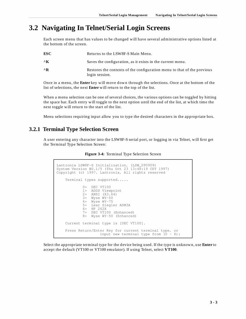
3.2.1 Terminal Type Selection Screen
A user entering any character into the LSW8F-S serial port, or logging in via Telnet, will first get the Terminal Type Selection Screen:
Figure 3-4: Terminal Type Selection Screen
Select the appropriate terminal type for the device being used. If the type is unknown, use Enter to accept the default (VT100 or VT100 emulator). If using Telnet, select VT100.
Lantronix LSW8F-S Initialization, (LSW_090909)System Version B0.1/5 (Thu Oct 23 13:48:19 CDT 1997)Copyright (c) 1997. Lantronix, All rights reserved
Terminal types supported.....
0> DEC VT100 1> ADDS Viewpoint 2> ANSI (X3.64) 3> Wyse WY-50 4> Wyse WY-75 5> Lear Siegler ADM3A 6> HP 262X 7> DEC VT100 (Enhanced) 8> Wyse WY-50 (Enhanced)
Current terminal type is [DEC VT100].
Press Return/Enter Key for current terminal type, or input new terminal type from (0 - 8):
3 - 3

Navigating In Telnet/Serial Login Screens Telnet/Serial Login Management
3.2.2 Main Menu Screen
The next menu that will appear is the Main Menu.
Figure 3-5: LSW8-F Main Menu Screen
The Main Menu provides you with an entry point into the various configuration option menus. The following figure shows the specific parameters that the different management and configura-tion menus contain.
At this point, the System Password is required to enter any of the configuration menus. The default value for this password is system (see System Password for more detailed information). Once the correct password has been entered, the LSW8F-S will proceed to the selected screen.
Table 3-1: Management and Configuration Parameters
Configuration Category Configurable Parameters
Network Hostname, IP address, Netmask, Gateway Spanning Tree, System Password
SNMP/RMON Entry to System, Host, Community Menus
Switch Entry to Filter, VLAN, Port Option Menus
Statistics Packet Traffic Counts, Packet Error Counts
< MAIN MENU > Lantronix, LSW8F-S 10/23/97 17:40:04
LSW8FS MAIN MENU
(N)-->Network Configuration (S)-->SNMP Configuration LANTRONIX (W)-->Switch Configuration LSW8FS (I)-->Statistics
Managed 10/100 Ethernet Switch (A)-->About LSW8FS (Q)-->Quit Current Session
Enter Menu Selection..........[ ]
3 - 4

Telnet/Serial Login Management Navigating In Telnet/Serial Login Screens
3.2.3 The Network Configuration Screen
The Network Configuration Screen allows you to select parameters that affect how the LSW8F-S interacts with other switching devices specifically, or with other network devices in general.
Figure 3-6: Network Configuration Screen
The following sections explain the configurable parameters in this menu.
3.2.3.1 Date/Time
Set the appropriate date and time, when the unit is first configured using the formats mm/dd/yy and hh:mm:ss. Once the selection has been saved, the LSW8F-S real-time clock will maintain the correct date and time.
NOTE: The real-time clock will maintain timing information for up to several weeks, even after the unit has been powered off. Beyond that time period, the LSW8F-S may require that the Date/Time information be updated.
3.2.3.2 Spanning Tree
The LSW8F-S allows you to enable or disable support for the Spanning Tree Algorithm. The default value is ON. This allows for the LSW8F-S to be safely placed into any network supporting Spanning Tree, with the knowledge that it will participate in the negotiations between the switches and bridges. This option can be toggled to the OFF setting by hitting the space bar.
NOTE: See Chapter 7 for a detailed discussion of Spanning Tree.
3.2.3.3 SNMP Security
Select ON to require SNMP host/community name entry for connection, or OFF to allow anyone to connect to the LSW8F-S.
< Network Configuration > Lantronix, LSW8F-S 10/23/97 17:41:17
Date/Time [10/23/97 17:40:51]
Spanning Tree Enable [ON ]
SNMP Security Enable [ON ]
Network Host Name [LSW_090909 ] IP Address [192.0.192.22 ] Netmask [255.255.255.0 ] Default Gateway [192.0.192.1 ]
User Password [ ]
================================================================================ >>>>> Change the DATE/TIME, format: MM/DD/YY HH:MM:SS [ESC] Main-Menu [^K] Save [^R] Restore
3 - 5

Navigating In Telnet/Serial Login Screens Telnet/Serial Login Management
3 - 6
3.2.3.4 Network Host Name
Some users find it helpful to refer to nodes on their network via host names rather than IP addresses. The LSW8F-S receives a unique host name from a combination of its product name, and its unique Ethernet address. The default host name of each LSW8F-S is of the form LSW_xxxxxx, where xxxxxx is the last six bytes of the unit’s Ethernet address.
The host name can be changed to a new value of up to 32 alphanumeric characters in length.
NOTE: Changing the host name of the LSW8F-S while connected via Telnet will cause the connection to be terminated.
3.2.3.5 IP Address
The LSW8F-S IP address is specified in this selection. The format for the address will be in the standard IP address format of 4 octets delimited by periods.
NOTE: Changing the IP address of the LSW8F-S while connected via Telnet will cause the connection to be terminated.
3.2.3.6 Netmask
The default Netmask for the LSW8F-S is class C (255.255.255.0). Users intending to use other net-work classes, or who intend to do subnetting, should make sure to make the necessary changes to this parameter.
3.2.3.7 Default Gateway
For connections that will go outside the local network, a Gateway should be specified. Although the LSW8F-S does not support outbound Telnet connections, it does support SNMP or RMON and, in some cases, will require that a Gateway be configured.
3.2.3.8 System Password
The System Password is required for entry into any of the LSW8F-S management and configura-tion screens. The default value for the password is system. It is strongly recommended that this password be changed as soon as possible.
NOTE: The password is NOT visible in this option box. If a new password is selected, make sure that it is entered correctly and recorded in a safe place.
If the password is lost or forgotten, the only way to set it back to the default is to flush the unit’s configuration back to all of its original defaults (via Boot Command Mode input).

Telnet/Serial Login Management Navigating In Telnet/Serial Login Screens
3.2.4 About Screen
The About Screen supplies relevant information regarding the LSW8F-S hardware and software, its Ethernet address and RAM configuration, as well as contact information for Lantronix.
Figure 3-7: About Screen
Additionally, the screen provides a description of the product and its settings and revision levels, which will be helpful when contacting Lantronix.
3.2.5 Quit Current Session
The Quit Current Session option allows you to exit from the serial port login session. Exiting via the Q command will reset the LSW8F-S, and the next login attempt will require entry of the sys-tem password to gain access to the configuration or management screens.
< About Screen > Lantronix, LSW8F-S 10/23/97 17:46:27
Lantronix15353 Barranca ParkwayIrvine, Californina 92618-2216
Support (Domestic)....... (800) 422-7055Support (International).. (714) 450-7232FAX...................... (714) 450-7226Sales.................... [email protected].................. [email protected] Wide Web........... www.lantronix.com
Ethernet Switch...... LSW8F-SSystem Version....... B0.1/5
RAM Installed........ 2097152 BytesTerminal Emulation... vt100MAC Address.......... 00:80:A3:09:09:09
==========================================================================[ESC] Main-Menu
3 - 7


4 SNMP
4.1 Overview............................................................................................................................ 4-1
4.2 Configuration .................................................................................................................... 4-1
4.2.1 Telnet/Serial Configuration ....................................................................... 4-2
4.2.2 EZWebCon Configuration.......................................................................... 4-5


SNMP Overview
4 - SNMP
4.1 OverviewSNMP, the Simple Network Management Protocol, is a mechanism used to control and monitor the behavior of a network appliance. This network appliance may be an Ethernet Switch, Router, RMON Probe, or any network-capable device. SNMP is defined by a set of core RFC (Requests for Comments) which are specifications describing its implementation and behavior. These RFCs are numbered 1155 through 1157. These documents describe version 1 of SNMP, which is by far the most popular of the available SNMP incarnations.
SNMP defines a relationship between an SNMP agent, on the to-be-monitored device, and an SNMP manager, on the user management station. SNMP identifies elements of a database, which describe statistics and control variables on the device. These elements are identified by a unique string of numbers. Get requests (Reads) from the SNMP manager retrieve information from the SNMP agent. Set requests (Writes) from the SNMP manager change information on the device monitored by the SNMP agent. The SNMP agent may provide unsolicited traps, or asynchronous event indications, to the SNMP manager as well.
The SNMP managers, or hosts that communicate with the SNMP agent, must be members of a defined community. An SNMP community is a collection of hosts which have certain permissions, among them GET (Read), SET (Write) and TRAP (asynchronous event). An SNMP host, or man-ager, may belong to more than one community.
SNMP must have a pre-defined community in order to be used.The default community is public. After a community has been created, trusted hosts or SNMP managers may be added to the com-munity.
The LSW8F-S will initially allow connection from any host or community at power-up. Refer to SNMP Security on page 2-6 (EZWebCon) or SNMP Security on page 3-5 (serial/Telnet) for informa-tion on Secure operation.
4.2 ConfigurationThe SNMP Community Screen and SNMP Host Screen may be used to set up these parameters. In EZWebCon, the COMM and HOST group in the Enterprise MIB may be used.
4 - 1

Configuration SNMP
4 - 2
4.2.1 Telnet/Serial Configuration
The SNMP Community Screen and SNMP Host Screen are used to configure SNMP community and SNMP hosts for the LSW8F-S.
Figure 4-1: Main Menu Screen
Select the SNMP/RMON option in the Main Menu Screen to reach the SNMP/RMON Configura-tion Screen.
Figure 4-2: SNMP/RMON Configuration Menu Screen
Once in the SNMP/RMON Configuration Screen, select either a System, Host, or Community con-figuration option. Host and Community configurations are the relevant parameters for SNMP access.
< MAIN MENU > Lantronix, LSW8F-S 10/23/97 17:40:04
LSW8FS MAIN MENU
(N)-->Network Configuration (S)-->SNMP Configuration LANTRONIX (W)-->Switch Configuration LSW8FS (I)-->Statistics
Managed 10/100 Ethernet Switch (A)-->About LSW8FS (Q)-->Quit Current Session
Enter Menu Selection..........[ ]
< SNMP/RMON Configuration > Lantronix, LSW8F-S 10/23/97 17:42:12
Select SNMP/RMON Configuration
(S)-->System Configuration (H)-->Host Configuration (C)-->Community Configuration
Enter Menu Selection........[ ]
================================================================================ >>>>> Choose the SNMP configuration sub-menu [ESC] Main-Menu

SNMP Configuration
4.2.1.1 Host Configuration Menu
In order for a device running SNMP to access the LSW8F-S, that device must be “known” to the LSW8F-S. The Host Configuration Menu allows you to specify the devices that the LSW8F-S can support for SNMP connections. This feature allows you to ensure that only authorized devices can communicate with the LSW8F-S. Enter up to 16 host systems, their IP addresses, and their com-munity membership for access to the LSW8F-S.
Figure 4-3: Host Configuration Menu Screen
Enter the name of the host, the IP address of the host, and the community of the host (the default is public). ^K will save the selections at any time, and make those selections active. The Enter key will move to the next selection and a wrap to the top of the screen after the last selection in the table.
< Host Configuration > Lantronix, LSW8F-S 10/23/97 17:43:21
Host Name Host IP Address Community
1[Host ] [-- undefined --] [public ] 2[Host1 ] [-- undefined --] [public ] 3[Host2 ] [-- undefined --] [public ] 4[Host3 ] [-- undefined --] [public ] 5[Host4 ] [-- undefined --] [public ] 6[Host5 ] [-- undefined --] [public ] 7[Host6 ] [-- undefined --] [public ] 8[Host7 ] [-- undefined --] [public ] 9[Host8 ] [-- undefined --] [public ] 10[Host9 ] [-- undefined --] [public ] 11[Host10 ] [-- undefined --] [public ] 12[Host11 ] [-- undefined --] [public ] 13[Host12 ] [-- undefined --] [public ] 14[Host13 ] [-- undefined --] [public ] 15[Host14 ] [-- undefined --] [public ] 16[Host15 ] [-- undefined --] [public ]
================================================================================ >>>>> Enter an SNMP manager (trusted host) name [ESC] Main-Menu [^K] Save [^R] Restore
4 - 3

Configuration SNMP
4.2.1.2 Community Configuration Menu
The Community Configuration Menu allows you to assign the supported SNMP features to a given community.
Figure 4-4: Community Configuration Menu Screen
The following functions are supported by these features:
Get Any host in this community can retrieve SNMP variables.
Set Any host in this community can modify SNMP variables.
Trap Any host in this community will receive alarms when an alarm condition, called a trap, has occurred.
The community name is entered as an alpha-numeric string, while the individual Get, Set and Trap parameters are changed by toggling the values with a space. The Enter key will move to the next parameter. When the end of the list is reached, the next Enter will return to the first selection. ^K will save the currently displayed values and make them active. ^R will return the values to those in effect at the last save (or to the defaults, if no save has been made).
< Community Configuration > Lantronix, LSW8F-S 10/23/97 17:43:44
Permission
Community Name Get Set Trap
[public ] [ON ] [ON ] [ON ] [ ] [OFF] [OFF] [OFF] [ ] [OFF] [OFF] [OFF] [ ] [OFF] [OFF] [OFF] [ ] [OFF] [OFF] [OFF] [ ] [OFF] [OFF] [OFF] [ ] [OFF] [OFF] [OFF] [ ] [OFF] [OFF] [OFF]
================================================================================ >>>>> Enter an SNMP community name [ESC] Main-Menu [^K] Save [^R] Restore
4 - 4

SNMP Configuration
4.2.2 EZWebCon Configuration
EZWebCon users can access the Host and Community configuration screens via the EZWebCon Main Menu Screen
Figure 4-5: Main Menu Screen
Click on the Configuration option to access the Host and Community configuration screens, as well as many others.
4.2.2.1 System Configuration Screen
Figure 4-6: System Configuration Screen
The System Configuration Screen provides current status information for the LSW8F-S.
The selection for Secure mode for SNMP/RMON connections is made on this screen as well. See SNMP Security on page 2-6 for more information.
4 - 5

Configuration SNMP
4.2.2.2 Host Configuration Screen
The EZWebCon Host Configuration Screen is accessed by double-clicking on the Host option in the Selection window.
Figure 4-7: Host Configuration Screen
Enter the host name, the host IP address, and community. Once the appropriate information is entered, click Save.
4.2.2.3 Community Configuration Screen
The EZWebCon Community Configuration Screen can be reached by double-clicking Community in the Selection window.
Figure 4-8: Community Configuration Screen
Enter the appropriate community names, then specify the state of the Get, Set and Trap options for that community. Click Save to preserve changes made in the table.
4 - 6

5 RMON
5.1 RMON Groups .................................................................................................................. 4-1
5.2 RMON Set-up .................................................................................................................... 4-1
5.3 Using RMON ..................................................................................................................... 4-2
5.3.1 Using EZWebCon to Access RMON ......................................................... 4-2
5.3.2 Using HP OpenView for Windows to access RMON........................... 4-15
5.3.3 Using SNMPc to access RMON ............................................................... 4-15
5.3.4 History Group ............................................................................................ 4-17

RMON RMON Groups
5 - RMONThe RMON (Remote Monitoring MIB), defined by RFC 1757, provides a mechanism for using the SNMP protocol to gather information about Ethernet segments. Segment-wide, MAC-layer statis-tics are gathered for the segment as a whole, and also for individual addresses seen on the seg-ment. In addition, alarms may be set up, on certain thresholds defined by the user. RMON also has a provision for capturing packets seen on the segment, with or without qualification by user-defined filters.
There are two versions of RMON. RMON Version 1 deals with MAC layer statistics and is widely used. RMON2 deals with Network layer statistics and is not widely used, due to processor and memory constraints.
5.1 RMON GroupsRMON supports nine categories of information. Those supported by the LSW8F-S are marked with asterisks (*).
Group 1* Ethernet MAC-layer statistics, MAC-layer statistics for the segment.
Group 2* History MAC-layer statistics for the segment, in previous time.
Group 3* Alarm conditions for SNMP manager event notification.
Group 4 Hosts, the MAC source addresses seen on the segment, and statistics kept for the address.
Group 5 HostTopN, the Top “N” source addresses, with regard to traffic seen on the segment.
Group 6 Matrix the MAC source and destination address pairs seen on the seg-ment, and statistics kept for the pair.
Group 7 Filter, set up limiting conditions on which packets to capture.
Group 8 Capture packets into buffers on the device, subject to conditions set up by the filter.
Group 9* Event-specific indication, generated when an Alarm condition is met. Traps are usually sent as event notifiers.
These groups provide information on the segment as a whole, with regard to current and past per-formance, current and past errors, most active conversations on the segment, most active nodes on the segment, and the type of packet traffic sent.
The LSW8FS supports RMON groups 1, 2, 3 and 9 in hardware to reduce processing limitations. These groups: Statistics, History, Alarm, and Event, provide information sufficient for an adminis-trator to determine the status of the network, and to set alarms for important thresholds.
5.2 RMON Set-upThe LSW8F-S RMON runs continuously on all ports. There is no setup other than the SNMP com-munity and host setup previously described. Some SNMP managers, such as HP Openview, require that the RMON MIB (RFC 1757) be compiled into the database before access is possible. Other SNMP managers, such as SNMPc, already have built-in support for the RMON MIB.
5 - 1

Using RMON RMON
5 - 2
Host systems wishing to access the LSW8F-S RMON can do so via management software applica-tions configured for RMON, such as HP Openview or Sun NetManager, or via other software, such as Castle Rock Computing’s SNMPc which has an integral RMON component.
Since RMON requires SNMP, the LSW8F-S must have a community defined for SNMP. The default community name is public. After a community has been created, RMON can be accessed from hosts with membership in that community. The procedure for setting up SNMP hosts and communities can be found in Overview.
The nature of RMON configuration and display makes it very difficult to present a user-friendly telnet or serial interface for RMON. For this reason, it is recommended that EZWebCon be used for the configuration and management of the LSW8F-S RMON.
NOTE: The LSW8F-S will allow connection from any host or community on initial power-up. See SNMP Security on page 2-6 for an explanation of Secure operating mode before proceeding.
5.3 Using RMONThe LSW8F-S supports four groups of RMON: Alarms, Events, History and Statistics. Users wish-ing to access RMON information on the LSW8F-S can use EZWebCon or standards-based RMON (using HP Openview, SNMPc or some other package). The EZWebCon interface simplifies some of the steps to obtaining RMON information for those who are unfamiliar with the RMON stan-dards.
5.3.1 Using EZWebCon to Access RMON
EZWebcon allows you to easily and simply use the capabilities supported by the RMON groups comprised of Alarms, Events and History (logging). These groups allow you to specify certain conditions which will trigger SNMP traps or logging of an event in a file. The benefit of these alarms and resultant events is pro-active awareness of network conditions, which allows you to react in time to avoid major catastrophes.
5.3.1.1 Alarms
After selecting the Configuration option in the EZWebCon Main Menu Screen, select Alarm in the Selection window.
Figure 5-1: Alarm Screen

RMON Using RMON
The Alarm Group periodically takes statistical samples from variables in the LSW8F-S, and com-pares them to the configured thresholds. If a monitored variable crosses a threshold, an event is generated. This group requires the implementation of the Event Group as well.
The following variables have been defined for the Alarm Group in the RMON specifications:
Index An index that uniquely identifies an entry in the alarm table. Each such entry defines a diagnostic sample at a particular interval for an object on the device.
Interval The interval in seconds over which the data is sampled and compared with the rising and falling thresholds.
Variable The object identifier of the particular variable to be sampled. This is the unique numeric identifier of the variable in OID notation.
Sample Type The method of sampling the selected variable and calculating the value to be compared against the thresholds. If the value of this object is absolute (1), the value of the selected variable will be compared directly with the thresholds at the end of the sampling interval. If the value of this object is delta (2), the value of the selected variable at the last sample will be sub-tracted from the current value, and the difference compared with the thresholds.
Value The value of the statistic during the last sampling period. For example, if the sample type is delta, this value will be the difference between the samples at the beginning and end of the period. If the sample type is absolute, this value will be the sampled value at the end of the period.
This is the value that is compared with the rising and falling thresholds.
StartUp Alarm The alarm that may be sent when this entry is first set to valid, if the sam-ple indicates that an alarm must be set. The values are Rising Alarm (1), Falling Alarm (2), Rising or Falling Alarm (3).
Rising Threshold A threshold for the sampled statistic. When the current sampled value is greater than or equal to this threshold, and the value at the last sampling interval was less than this threshold, a single event will be generated. A single event will also be generated, if the first sample after this entry becomes valid is greater than or equal to this threshold, and the associ-ated Startup Alarm is equal to Rising Alarm (1) or Rising Or Falling Alarm (3).
After a rising event is generated, another such event will not be generated until the sampled value falls below this threshold and reaches the alarm Falling Threshold.
Falling Threshold A threshold for the sampled statistic. When the current sampled value is less than or equal to this threshold, and the value at the last sampling interval was greater than this threshold, a single event will be generated. A single event will also be generated if the first sample, after this entry becomes valid, is less than or equal to this threshold, and the associated Startup Alarm is equal to Falling Alarm(2) or Rising Or Falling Alarm(3).
After a falling event is generated, another such event will not be gener-ated until the sampled value rises above this threshold and reaches the alarm Rising Threshold.
5 - 3

Using RMON RMON
Rising EventIndex The index of the eventEntry that is used when a rising threshold is crossed. The eventEntry identified by a particular value of this index is the same as identified by the same value of the eventIndex object. If there is no corresponding entry in the eventTable, then no association exists. In particular, if this value is zero, no associated event will be generated, as zero is not a valid event index.
Falling EventIndex The index of the eventEntry that is used when a falling threshold is crossed. The eventEntry identified by a particular value of this index is the same as identified by the same value of the eventIndex object. If there is no corresponding entry in the eventTable, then no association exists. In particular, if this value is zero, no associated event will be generated, as zero is not a valid event index.
Owner The entity that configured this entry, and is therefore using the resources assigned to it. Just a text string.
5.3.1.1.1 Setting up or Changing Alarms
To set up an alarm, select the Add button. Then select the parameters associated with this alarm condition.
Figure 5-2: Alarm Configuration Screen
To modify an existing Alarm, select Edit and then edit the previous entries.
5.3.1.1.2 Port Selection
Select the port of the LSW8F-S which is going to be monitored.
Figure 5-3: Port Selection Screen
5 - 4

RMON Using RMON
5.3.1.1.3 Alarm Variables
Select any one of the following RMON variables as the basis for the alarm:
Octets The total number of octets of data (including those in bad packets) received on the network (excluding framing bits but including FCS octets).
Utilization This object can be used as a reasonable estimate of ethernet utilization. If greater precision is desired, the EtherStatsPkts and EtherStatsOctets objects should be sampled, before and after a common interval. The dif-ferences in the sampled values are Pkts and Octets, respectively, and the number of seconds in the interval is Interval. These values are used to cal-culate the Utilization as follows:
The result of this equation is the value Utilization, which is the percent utilization of the Ethernet segment on a scale of 0 to 100 percent.
Packets The total number of packets (including bad packets, broadcast packets, and multicast packets) received.
BroadCast Packets The total number of good packets received that were directed to the broadcast address. Note that this does not include multicast packets.
Multicast Packets The total number of good packets received that were directed to a multi-cast address. Note that this number does not include packets directed to the broadcast address.
CRC Align The total number of packets received that had a length of between 64 and 1,518 octets inclusive (excluding framing bits, but including FCS octets), but had either a bad Frame Check Sequence (FCS) with an integral num-ber of octets (FCS Error), or a bad FCS with a non-integral number of octets (Alignment Error).
Undersize Packets The total number of packets received that were less than 64 octets long (excluding framing bits, but including FCS octets), and were otherwise well formed.
Oversize Packets The total number of packets received that were longer than 1,518 octets (excluding framing bits, but including FCS octets), and were otherwise well formed.
Fragments The total number of packets received that were less than 64 octets in length (excluding framing bits but including FCS octets), and had either a bad Frame Check Sequence (FCS) with an integral number of octets (FCS Error), or a bad FCS with a non-integral number of octets (Alignment Error).
Jabbers The total number of packets received that were longer than 1,518 octets (excluding framing bits, but including FCS octets), and had either a bad Frame Check Sequence (FCS) with an integral number of octets (FCS Error), or a bad FCS with a non-integral number of octets (Alignment Error).
Packets * (9.6 + 6.4) + (Octets * 0.8)
Interval * 10,000
5 - 5

Using RMON RMON
Collisions The best estimate of the total number of collisions on this Ethernet seg-ment.
Pkts 64 Octets The total number of packets (including bad packets) received that were 64 octets in length (excluding framing bits but including FCS octets).
Pkts 65 to 127 Octets The total number of packets (including bad packets) received that were between 65 and 127 octets in length inclusive (excluding fram-ing bits but including FCS octets).
Pkts 128 to 255 Octets The total number of packets (including bad packets) received that were between 128 and 255 octets in length inclusive (excluding fram-ing bits but including FCS octets).
Pkts 256 to 511 Octets The total number of packets (including bad packets) received that were between 256 and 511 octets in length inclusive (excluding fram-ing bits but including FCS octets).
Pkts 512 to 1023 Octets The total number of packets (including bad packets) received that were between 512 and 1,023 octets in length inclusive (excluding framing bits but including FCS octets).
Pkts 1024 to 1518 Octets The total number of packets (including bad packets) received that were between 1,024 and 1,518 octets in length inclusive (excluding framing bits but including FCS octets).
Select the alarm variable by clicking on it in the Alarm Variable selection menu.
Figure 5-4: Variable Selection Screen
5 - 6
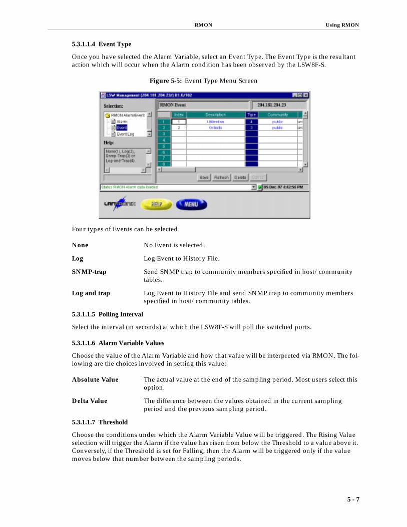
RMON Using RMON
5.3.1.1.4 Event Type
Once you have selected the Alarm Variable, select an Event Type. The Event Type is the resultant action which will occur when the Alarm condition has been observed by the LSW8F-S.
Figure 5-5: Event Type Menu Screen
Four types of Events can be selected.
None No Event is selected.
Log Log Event to History File.
SNMP-trap Send SNMP trap to community members specified in host/community tables.
Log and trap Log Event to History File and send SNMP trap to community members specified in host/community tables.
5.3.1.1.5 Polling Interval
Select the interval (in seconds) at which the LSW8F-S will poll the switched ports.
5.3.1.1.6 Alarm Variable Values
Choose the value of the Alarm Variable and how that value will be interpreted via RMON. The fol-lowing are the choices involved in setting this value:
Absolute Value The actual value at the end of the sampling period. Most users select this option.
Delta Value The difference between the values obtained in the current sampling period and the previous sampling period.
5.3.1.1.7 Threshold
Choose the conditions under which the Alarm Variable Value will be triggered. The Rising Value selection will trigger the Alarm if the value has risen from below the Threshold to a value above it. Conversely, if the Threshold is set for Falling, then the Alarm will be triggered only if the value moves below that number between the sampling periods.
5 - 7

Using RMON RMON
5.3.1.2 Events
Once you have specified an Alarm Condition and specified the type of Event(s) that will result, you can provide further documentation and description of that Event in the Event Table. Click on the Event selection to pull up the following screen.
Figure 5-6: Event Screen
The two fields that are of interest in the Event Table are those for Description and Community.
Description A comment field of up to 30 alphanumeric characters designed to allow the user to document the particular event. Simply click on the desired entry and then enter the text.
Community The Community field can be modified to allow various SNMP communi-ties to receive or have access to the information generated by the event. For instance, if the event is an SNMP-trap, every community listed in the table for that event will see that trap. By carefully selecting those commu-nities that are able to see this information, you can ensure the security of the LSW8F-S RMON information.
5 - 8
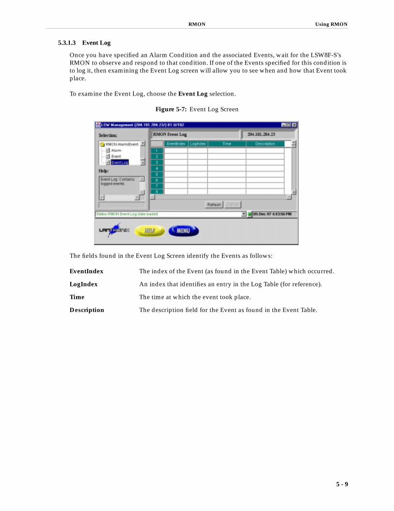
RMON Using RMON
5.3.1.3 Event Log
Once you have specified an Alarm Condition and the associated Events, wait for the LSW8F-S’s RMON to observe and respond to that condition. If one of the Events specified for this condition is to log it, then examining the Event Log screen will allow you to see when and how that Event took place.
To examine the Event Log, choose the Event Log selection.
Figure 5-7: Event Log Screen
The fields found in the Event Log Screen identify the Events as follows:
EventIndex The index of the Event (as found in the Event Table) which occurred.
LogIndex An index that identifies an entry in the Log Table (for reference).
Time The time at which the event took place.
Description The description field for the Event as found in the Event Table.
5 - 9
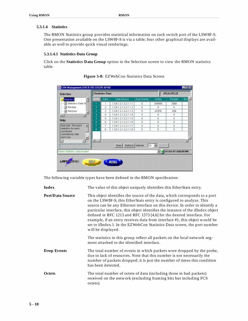
Using RMON RMON
5.3.1.4 Statistics
The RMON Statistics group provides statistical information on each switch port of the LSW8F-S. One presentation available on the LSW8F-S is via a table; four other graphical displays are avail-able as well to provide quick visual renderings.
5.3.1.4.1 Statistics Data Group
Click on the Statistics Data Group option in the Selection screen to view the RMON statistics table.
Figure 5-8: EZWebCon Statistics Data Screen
The following variable types have been defined in the RMON specification:
Index The value of this object uniquely identifies this EtherStats entry.
Port/Data Source This object identifies the source of the data, which corresponds to a port on the LSW8F-S, this EtherStats entry is configured to analyze. This source can be any Ethernet interface on this device. In order to identify a particular interface, this object identifies the instance of the ifIndex object defined in RFC 1213 and RFC 1573 [4,6] for the desired interface. For example, if an entry receives data from interface #1, this object would be set to ifIndex.1. In the EZWebCon Statistics Data screen, the port number will be displayed.
The statistics in this group reflect all packets on the local network seg-ment attached to the identified interface.
Drop Events The total number of events in which packets were dropped by the probe, due to lack of resources. Note that this number is not necessarily the number of packets dropped; it is just the number of times this condition has been detected.
Octets The total number of octets of data (including those in bad packets) received on the network (excluding framing bits but including FCS octets).
5 - 10

RMON Using RMON
Utilization This object can be used as a reasonable estimate of ethernet utilization. If greater precision is desired, the EtherStatsPkts and EtherStatsOctets objects should be sampled, before and after a common interval. The dif-ferences in the sampled values are Pkts and Octets, respectively, and the number of seconds in the interval is Interval. These values are used to cal-culate the Utilization as follows:
The result of this equation is the value Utilization, which is the percent utilization of the Ethernet segment on a scale of 0 to 100 percent.
Packets The total number of packets (including bad packets, broadcast packets, and multicast packets) received.
BroadCast Packets The total number of good packets received that were directed to the broadcast address. Note that this does not include multicast packets.
Multicast Packets The total number of good packets received that were directed to a multi-cast address. Note that this number does not include packets directed to the broadcast address.
CRC Align The total number of packets received that had a length (excluding fram-ing bits, but including FCS octets) of between 64 and 1,518 octets, inclu-sive, but had either a bad Frame Check Sequence (FCS) with an integral number of octets (FCS Error), or a bad FCS with a non-integral number of octets (Alignment Error).
Undersize Packets The total number of packets received that were less than 64 octets long (excluding framing bits, but including FCS octets), and were otherwise well formed.
Oversize Packets The total number of packets received that were longer than 1,518 octets (excluding framing bits, but including FCS octets), and were otherwise well formed.
Fragments The total number of packets received that were less than 64 octets in length (excluding framing bits but including FCS octets), and had either a bad Frame Check Sequence (FCS) with an integral number of octets (FCS Error), or a bad FCS with a non-integral number of octets (Alignment Error).
Jabbers The total number of packets received that were longer than 1,518 octets (excluding framing bits, but including FCS octets), and had either a bad Frame Check Sequence (FCS) with an integral number of octets (FCS Error), or a bad FCS with a non-integral number of octets (Alignment Error).
Collisions The best estimate of the total number of collisions on this Ethernet seg-ment.
Pkts 64 Octets The total number of packets (including bad packets) received that were 64 octets in length (excluding framing bits but including FCS octets).
Pkts 65 to 127 Octets The total number of packets (including bad packets) received that were between 65 and 127 octets in length inclusive (excluding fram-ing bits but including FCS octets).
Packets * (9.6 + 6.4) + (Octets * 0.8)
Interval * 10,000
5 - 11

Using RMON RMON
Pkts 128 to 255 Octets The total number of packets (including bad packets) received that were between 128 and 255 octets in length inclusive (excluding fram-ing bits but including FCS octets).
Pkts 256 to 511 Octets The total number of packets (including bad packets) received that were between 256 and 511 octets in length inclusive (excluding fram-ing bits but including FCS octets).
Pkts 512 to 1023 Octets The total number of packets (including bad packets) received that were between 512 and 1,023 octets in length inclusive (excluding framing bits but including FCS octets).
Pkts 1024 to 1518 Octets The total number of packets (including bad packets) received that were between 1,024 and 1,518 octets in length inclusive (excluding framing bits but including FCS octets).
Owner The entity that configured this entry and is therefore using the resources assigned to it. Owner is a simple text string.
Status The status of this EtherStats entry.
The refresh interval for this table can be adjusted via the arrow next to the numerical interval. Clicking on Refresh will instantly refresh the display.
5.3.1.4.2 Packet Size
Some users prefer a graphical display for quick reference, as opposed to a detailed numerical dis-play. The Packet Sizes Screen in EZWebCon provides this information when you click the Pkt Size option in the Selection window.
Figure 5-9: Packet Sizes Screen
Observed packet size information is displayed in pie-chart format for a quick and easy graphical view. Clicking Refresh will immediately update the display; the refresh interval can be changed if desired.
5 - 12

RMON Using RMON
5.3.1.4.3 Packet Errors
Figure 5-10: Packet Errors Screen
Packet Errors can also be observed in a graphical format by selecting the Pkt Error option in the Selection window. The following packet errors can be observed:
• Drop Events
• CRC Alignment Errors
• Undersize Packets
• Oversize Packets
• Fragments
• Jabbers
Clicking Refresh will immediately update the display; the refresh interval can be changed if desired.
5 - 13

Using RMON RMON
5 - 14
5.3.1.4.4 Packet Type
The Packet Types Screen displays the relative proportions of ordinary packets, broadcast packets, and multicast packets for each LSW8F-S port.
Figure 5-11: Packet Types Screen
Click on Refresh to update immediately, and click on the arrow next to the interval to change it.
5.3.1.4.5 Summary
The Summary option in the EZWebCon Selection window allows you to observe comparative sta-tistics across all LSW8F-S ports. Each port value is color coded for easy identification.
Figure 5-12: Ether Stat Summary Screen
The interval time for each sample can be adjusted by using the arrow next to the interval time win-dow. The data being shown can be changed by using the arrow next to the current data type dis-play.

RMON Using RMON
5.3.2 Using HP OpenView for Windows to access RMON
Since LSW8F-S operates as a normal SNMP device on the network, any SNMP-based network management application should be able to manage it properly. The only issue lies in the area of monitoring Lantronix-specific MIBs where compilation of Lantronix MIB file is required. The fol-lowing instruction outlines the steps needed to manage LSW8F-S under HP OpenView. Note that the instruction is based on HP OpenView for Windows version D.01.02. It serves only as a guide-line for other versions of HP OpenView.
1. Make sure HP OpenView is properly installed.
2. Assign and set up an IP address for LSW8F-S.
3. Add the IP address of the management station to LSW8F-S’s host table via either the serial port console or a Telnet session.
4. Start the HP OpenView auto-discovery process by using sub-menus under Autodiscovery:
A. Configure - Discovery Networks... defines the network domain where LSW8F-S resides. To speed up the discovery process, user can optionally specify the existence of LSW8F-S by using User Specified Devices... sub-menu.
B. Discover - Discovery Manager discovers all devices within defined net-work domains.
C. Layout - Do Basic Layout draws the network map in which LSW8F-S should appear as an SNMP device.
5. Compile RMON MIBs by issuing the menu command Control-SNMP Man-ager-Manage Database.
Make sure that RFC1213.MIB is already in the MIB database and add the file RFC1757.MIB into the database. For some older versions of HP OpenView, the RFC1757.MIB file may not appear on the selection list, in which case you must request this file from HP technical support.
6. If managing Lantronix enterprise MIBs is desired, copy the file LTX.MIB from the release CD into ‘MIBS’ subdirectory where HP OpenView is installed. Com-pile LTX.MIB file as described in Step 5. The LSW8F-S MIBs can then be found under iso.org.dod.internet.private.enterprises.ltx.ltxlsw.
7. Use the Control-SNMP Manager-Define Query... menu command to query MIBs in the MIB-II group, the RMON group, and the enterprise-specific group.
5.3.3 Using SNMPc to access RMON
SNMPc is a Windows application for managing SNMP-based network devices. It provides similar functionality as HP OpenView for Windows, thus much of the instruction for setting up HP Open-View are, in principle, applicable for SNMPc. The following instructions were written for version 4.2.
1. Make sure SNMPc is properly installed.
2. Assign and set up an IP address for LSW8F-S.
3. Add the IP address of the management station to LSW8F-S host table via either the serial port console or a Telnet session.
5 - 15

Using RMON RMON
4. Start the SNMPc auto-discovery process by using commands under Edit-Dis-cover Nodes:
A. Setup-Add sets up the starting address of network domain where LSW8F-S resides. To speed up the discovery process, you may specify the LSW8F-S’s IP address here.
B. Start discovers all devices within defined network domains.
C. Layout draws the network map in which LSW8F-S should appear as an SNMP device.
5. Use the following sub-menus of the Manage menu to monitor MIB-II variables:
A. System: MIB-II System group.
B. Interfaces: MIB-II Interface group.
C. Bridge: MIB-II Bridge group.
6. Use RMON-Set Network Probe... to set up the probe node, specify the Probe Type as other, then click Set.
This operation will invoke a “Fail to enable probe” message because LSW8F-S does not support the RMON Host group. Just ignore this message and proceed. You only need to run Set Network Probe... once, then use the following sub-menus to monitor RMON four groups:
A. Statistics displays RMON Ethernet Statistics table.
B. History displays RMON History table.
C. Alarm displays combined RMON Alarm/Event tables.
7. If managing Lantronix enterprise MIBs is desired, copy the file LTX.MIB from the release CD into the MIBFILES subdirectory where SNMPc is installed. Com-pile the LTX.MIB file by using the Add and Load commands under the Config-Compile MIB... menu command. Use the Manage-Display MIB Table... menu command to view the LSW8F-S MIBs which can be found under [private][ltx]. 8. SNMPc Hubview is supported by double-clicking the LSW8F-S icon.
5 - 16

RMON Using RMON
5.3.4 History Group
The RMON history group records periodic statistical samples from a network and stores them for later retrieval. The history control table stores configuration entries that each defines an interface/port and parameters for the sampling function. Each port in the LSW8F-S adds two history control entries that describe a short term (30 seconds) and a long term (30 minutes) polling period. Once samples are taken, their data is stored in an entry (a bucket) in the history data table. Each such entry defines one sample and is associated with an entry in the control table that caused the sam-ple to be taken. EZWebCon supports the specification of how data is sampled and the display of collected data in various formats, such as data matrix, line chart, and bar chart.
5.3.4.1 History Control Table
Click on the Control Grid option in the Selection window to specify how network data can be sampled on the LSW8F-S.
Figure 5-13: History Control Screen
Specify the following parameters for data collection:
Index An index that uniquely identifies an entry in the historyControl table. Each such entry defines a set of samples at a particular interval for an interface on the device.
Port/Data Source This object identifies the source of the data, which corresponds to a port on the LSW8F-S for which historical data was collected and placed in a media-specific table on behalf of this historyControlEntry. This source can be any interface on the LSW8F-S. In order to identify a particular inter-face, this object will identify the instance of the ifIndex object (defined in RFC 1213 and RFC 1573 [4,6]) for the desired interface. For example, if an entry were to receive data from interface #1, this object would be set to ifIndex.1. In the EZWebCon History Control screen, the port number will be displayed.
The statistics in this group reflect all packets on the local network seg-ment attached to the identified interface.
Buckets Requested The requested number of discrete time intervals over which data is to be saved, in the part of the media-specific table associated with this history-ControlEntry.
5 - 17

Using RMON RMON
Buckets Granted The number of discrete sampling intervals over which data shall be saved, in the part of the media-specific table associated with this history-ControlEntry. The default value is 50.
Interval The interval in seconds over which the data is sampled for each bucket, in the part of the media-specific table associated with this historyControlEn-try. This interval can be set to any number of seconds between 1 and 3600 (1 hour).
Owner The entity that configured this entry and is therefore using the resources assigned to it. Just a text string.
Click on Save to preserve the changes made in this session. Click Refresh to return to the prior configuration.
5.3.4.2 History Data Table
The History Data Screen presents the data obtained from the execution of the parameters specified in the History Control Screen.
Figure 5-14: History Data Screen
The Refresh option immediately resets the screen display to the current values. The Control Index option allows you to select the index to be examined.
The following is an explanation of each value presented, as defined in the RMON specification:
Index The history of which this entry is a part.
Sample Index An index that uniquely identifies the particular sample this entry repre-sents, among all samples associated with the same historyControlEntry. This index starts at 1 and increments as each new sample is taken.
Interval Start The value of system Time at the start of the interval over which this sam-ple was measured.
5 - 18

RMON Using RMON
Drop Events The total number of events in which packets were dropped by the probe due to lack of resources during this sampling interval. Note that this number is not necessarily the number of packets dropped, it is just the number of times this condition has been detected.
Octets The total number of octets of data (including those in bad packets) received on the network (excluding framing bits but including FCS octets).
Packets The number of packets (including bad packets) received during this sam-pling interval.
Broadcast Pkts The number of good packets received during this sampling interval that were directed to the broadcast address.
Multicast Pkts The number of good packets received during this sampling interval that were directed to a multicast address. Note that this number does not include packets addressed to the broadcast address.
CRC Align Errors The number of packets received during this sampling interval that had a length (excluding framing bits but including FCS octets) between 64 and 1,518 octets, inclusive, but had either a bad Frame Check Sequence (FCS) with an integral number of octets (FCS Error), or a bad FCS with a non-integral number of octets (Alignment Error).
Undersize Pkts The number of packets received during this sampling interval that were less than 64 octets long (excluding framing bits but including FCS octets), and were otherwise well formed.
Oversize Pkts The number of packets received during this sampling interval that were longer than 1518 octets (excluding framing bits but including FCS octets), but were otherwise well formed.
Fragment Pkts The total number of packets received during this sampling interval that were less than 64 octets in length (excluding framing bits but including FCS octets) had either a bad Frame Check Sequence (FCS) with an inte-gral number of octets (FCS Error), or a bad FCS with a non-integral num-ber of octets (Alignment Error).
Jabbers The number of packets received during this sampling interval that were longer than 1,518 octets (excluding framing bits but including FCS octets), and had either a bad Frame Check Sequence (FCS) with an integral num-ber of octets (FCS Error), or a bad FCS with a non-integral number of octets (Alignment Error).
Collisions The best estimate of the total number of collisions on this Ethernet seg-ment during this sampling interval.
5 - 19

Using RMON RMON
5.3.4.3 History Line Chart
The History Line Chart is another format in which History Group data can be viewed
Figure 5-15: History Line Chart Screen
The Refresh option will reset the screen to current values. Select the desired Control Index for examination.
5.3.4.4 History Bar Chart
The History Bar Chart provides a bar chart format for viewing the History Group data.
Figure 5-16: History Bar Chart Screen
Select the Refresh option to reset the screen. Select the Control Index option to view the correct index and use the Data Type option to select the type of data to be viewed.
5 - 20

6 MIBs


MIBS
6 - MIBSThe LSW8F-S supports the following MIBs:
• RFC 1757 for RMON version 1, groups 1,2,3 and 9.
These MIBs provide statistics, history and alarm indications. This is suf-ficient for a network administrator to gain information regarding the performance of the network.
The RMON MIB runs automatically on all interfaces on power up, so there is no setup specific to this MIB.
• RFC 1213 for MIB2.
MIB2 provides information on the TCP/IP stack and the lower level interfaces on the switch.
MIB2 may be modified to set up certain parameters in the system group, but does not otherwise need to be modified from the defaults.
• RFC 1493, the Bridge MIB, groups Base and Stp.
The Bridge MIB provides statistics and control of the Spanning Tree component in the switch. Since the LSW8FS is not a bridge, groups TP and STATIC of the Bridge MIB are not required.
The Bridge MIB provides control over parameters governing the opera-tion of Spanning Tree, but the default Spanning Tree parameters are usually adequate for normal operation.
• LTX, the Lantronix Enterprise MIB.
The LTX MIB provides the capability to configure the system parame-ters of the switch, as well as to set up the SNMP configuration.
The Lantronix Enterprise MIB provides the ability to set up system parameters, including the SNMP community and host groups. The MIB definition file Ltx.mib is distributed as a text file on the release CD. The file can be compiled by network management applications, such as HP OpenView and SNMPc, to manage Lantronix Enterprise MIB variables.
6 - 1


7 Spanning Tree
7.1 Configuration .................................................................................................................... 4-2
7.1.1 Telnet/Serial Configuration ....................................................................... 4-2
7.1.2 EZWebCon Configuration.......................................................................... 4-3

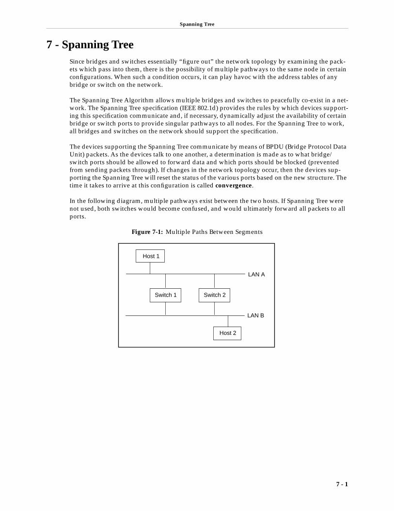
Spanning Tree
7 - Spanning TreeSince bridges and switches essentially “figure out” the network topology by examining the pack-ets which pass into them, there is the possibility of multiple pathways to the same node in certain configurations. When such a condition occurs, it can play havoc with the address tables of any bridge or switch on the network.
The Spanning Tree Algorithm allows multiple bridges and switches to peacefully co-exist in a net-work. The Spanning Tree specification (IEEE 802.1d) provides the rules by which devices support-ing this specification communicate and, if necessary, dynamically adjust the availability of certain bridge or switch ports to provide singular pathways to all nodes. For the Spanning Tree to work, all bridges and switches on the network should support the specification.
The devices supporting the Spanning Tree communicate by means of BPDU (Bridge Protocol Data Unit) packets. As the devices talk to one another, a determination is made as to what bridge/switch ports should be allowed to forward data and which ports should be blocked (prevented from sending packets through). If changes in the network topology occur, then the devices sup-porting the Spanning Tree will reset the status of the various ports based on the new structure. The time it takes to arrive at this configuration is called convergence.
In the following diagram, multiple pathways exist between the two hosts. If Spanning Tree were not used, both switches would become confused, and would ultimately forward all packets to all ports.
Figure 7-1: Multiple Paths Between Segments
LAN A
LAN B
Host 1
Switch 1 Switch 2
Host 2
7 - 1

Configuration Spanning Tree
In the next diagram, Spanning Tree is supported on both devices and one of the ports is “blocked,” so there is now only one path between the two hosts.
Figure 7-2: Network Using Spanning Tree Algorithm
Each disabled port will continue to listen to packet traffic, but will not forward any packets through the switch or transmit any packets out of the disabled port. When multiple paths to the same segment have been identified, the path(s) with the highest path cost will be disabled.
The Spanning Tree Algorithm will respond to changes in network configuration. If an Ethernet port has been disabled due to duplicate paths and the single operational path becomes inoperable, a disabled Ethernet port will be re-enabled to recreate the path.
7.1 Configuration
7.1.1 Telnet/Serial Configuration
The parameter for Spanning Tree configuration is contained in the Network Configuration Menu.
Figure 7-3: Network Configuration Screen
Toggle between ON/OFF states by hitting the space bar.
LAN A
LAN B
Host 1
Switch 1 Switch 2
Host 2
This LAN port isnow in the “blocking” state; it does nottransmit packets.
< Network Configuration > Lantronix LSW8F-S 10/08/97 19:09:20
Date/Time [10/08/97 19:09:13]
Spanning Tree Enable [ON ]
SNMP Security Enable [OFF]
Network Host Name [LSW_707070 ] IP Address [204.181.204.180] Netmask [255.255.255.0 ] Default Gateway [192.0.192.1 ]
User Password [ ]
================================================================================ >>>>> Change the DATE/TIME, format: MM/DD/YY HH:MM:SS [ESC] Main-Menu [^K] Save [^R] Restore
7 - 2

Spanning Tree Configuration
7.1.2 EZWebCon Configuration
The selection for Spanning Tree can be found in the Network option in the Selection window.
Figure 7-4: Network Option Screen
Click on the option bar and enter ON or OFF as desired.
7 - 3


8 VLANs
8.1 Telnet/Serial Configuration ............................................................................................ 4-1
8.2 EZWebCon Configuration............................................................................................... 4-2


VLANs Telnet/Serial Configuration
8 - 1
8 - VLANsThe LSW8F-S supports up to 8 port-based VLANs (Virtual Large Area Networks). Once selected as member of the VLAN, a port will receive all traffic directed to all other ports included in that VLAN. Broadcast traffic will be limited to VLAN members.
8.1 Telnet/Serial ConfigurationSelect the VLAN option in the Switch Configuration Menu to reach the VLAN Configuration Menu.
Figure 8-1: Switch Configuration Menu Screen
Once in the VLAN Configuration Menu, select the VLAN name, whether or not the VLAN should be enabled, and the ports to be included.
Figure 8-2: VLAN Configuration Menu Screen
Use the ^N and ^P keys to move from VLAN to VLAN.
< Switch Configuration > Lantronix, LSW8F-S 10/23/97 17:44:10
Select Switch Configuration
(F)-->Filters Configuration (P)-->Ports Configuration (V)-->VLAN Configuration
Enter Menu Selection........[ ]
================================================================================ >>>>> Select the Switch Configuration sub-menu [ESC] Main-Menu
< VLAN Configuration > Lantronix, LSW8F-S 10/23/97 17:45:09
VLAN Name [ ] Enabled [OFF ]
Select Port Membership for VLAN
Port 1 member [ON ] Port 2 member [ON ] Port 3 member [ON ] Port 4 member [ON ] Port 5 member [ON ] Port 6 member [ON ] Port 7 member [ON ] Port 8 member [ON ]
================================================================================ >>>>> Edit or create a VLAN name [ESC] Main-Menu [^K] Save [^D] Delete [^N] Next [^P] Prev [^R] Restore

EZWebCon Configuration VLANs
8.2 EZWebCon ConfigurationFigure 8-3: VLAN Configuration Screen
Click on the row number on the far left to edit the port numbers to be included in the VLAN.
Figure 8-4: VLAN Edit Screen
8 - 2

9 Port Configuration
9.1 Telnet/Serial Port Configuration.................................................................................... 4-1
9.2 EZWebCon Port Configuration ...................................................................................... 4-2


Port Configuration Telnet/Serial Port Configuration
9 - Port ConfigurationThe eight RJ45 ports of the LSW8F-S are capable of supporting auto-negotiating for both speed and duplex mode. They conform to the IEEE 802.3u clause 28 for support of these features, and should therefore be compatible with other devices supporting the same standard.
In some cases, however, the network may have legacy 10 Mbps or 100 Mbps devices that cannot autonegotiate, or vendor equipment that does not conform to the standard. To facilitate compati-bility with such devices, you can override the LSW8F-S default autonegotiating sequence on a per port basis, as well as select and fix both port speed and duplex mode.
9.1 Telnet/Serial Port ConfigurationFrom the Main Menu, select the Port Configuration option. The following Port Configuration Menu Screen will appear:
Figure 9-1: Port Configuration Menu Screen
Toggle through and select any one of the following options for any of the eight LSW8F-S ports.
Auto Automatic auto-negotiating (the default).
Half_10 Half duplex mode; speed 10 Mbps.
Half_100 Half duplex mode; speed 100 Mbps.
Full_10 Full duplex mode; speed 10 Mbps.
Full_100 Full duplex mode: speed 100 Mbp.
Disabled Port disabled.
Press ^K to save your selections.
< Port Configuration > Lantronix, LSW8F-S 10/23/97 17:44:49
LSW8FS Port Properties
Port 1 [AUTO ] Port 2 [AUTO ] Port 3 [AUTO ] Port 4 [AUTO ] Port 5 [AUTO ] Port 6 [AUTO ] Port 7 [AUTO ] Port 8 [AUTO ]
================================================================================ >>>>> Select the port mode [ESC] Main-Menu [^K] Save [^R] Restore
9 - 1

EZWebCon Port Configuration Port Configuration
9.2 EZWebCon Port ConfigurationFrom the EZWebCon Main Menu, click Configuration. Double-click on Port in the Selection win-dow.
Figure 9-2: Port Configuration Screen
Select the appropriate setting for each port. Then click Save to configure the LSW8F-S as per the screen selections.
9 - 2

10 Statistics


Statistics
10 - StatisticsRMON provides the most detailed statistical information available on the LSW8F-S. See Chapter 5 for details on how to access this data.
For some users, however, quick access to the LSW8F-S via Telnet or the serial interface is preferred. A simple statistical table can be reached via these interfaces.
Figure 10-1: Main Menu Screen
Enter I to select the Statistics option in the Main Menu.
Figure 10-2: Statistics Menu Screen
< MAIN MENU > Lantronix, LSW8F-S 10/23/97 17:40:04
LSW8FS MAIN MENU
(N)-->Network Configuration (S)-->SNMP Configuration LANTRONIX (W)-->Switch Configuration LSW8FS (I)-->Statistics
Managed 10/100 Ethernet Switch (A)-->About LSW8FS (Q)-->Quit Current Session
Enter Menu Selection..........[ ]
< Statistics > Lantronix, LSW8F-S 10/23/97 17:45:40
LSW8FS Statistics
Packets Errors
In-----------Out In-----------Out
Port 1 [1648 ] [0 ] [0 ] [0 ] Port 2 [0 ] [0 ] [0 ] [0 ] Port 3 [176 ] [0 ] [0 ] [0 ] Port 4 [0 ] [0 ] [0 ] [0 ] Port 5 [0 ] [0 ] [0 ] [0 ] Port 6 [0 ] [0 ] [0 ] [0 ] Port 7 [0 ] [0 ] [0 ] [0 ] Port 8 [0 ] [0 ] [0 ] [0 ]
Totals [1824 ] [0 ] [0 ] [0 ]
================================================================================
[ESC] Main-Menu
10 - 1

Statistics
The Statistics Screen presents a self-updating display of packet and error-count statistics for each port on the LSW8F-S. The following are the included data types:
Packets Data packets, broadcast packets, multicast packets.
Errors Error packets.
These counts are totalled for all ports, divided into groups of those received and those transmit-ted.
Press ESC to return to the Main Menu.
10 - 2

Technical Support Lantronix Problem Report Procedure
A - Technical SupportIf the LSW detects a software error, it will attempt to display the cause and circumstances of the error on the terminal attached to the console port. See Appendix B, Troubleshooting, for more infor-mation.
A.1 Lantronix Problem Report ProcedureIf you are experiencing problems with the LSW8F-S or have suggestions for improving the prod-uct, please contact Lantronix Technical Support at (800) 422-7044 or (714) 453-3990. We are also reachable via Internet email at [email protected].
If you are submitting a problem, please provide the following information:
• Your name, company name, address, and phone number
• Product name
• Unit serial number
• Software version
• Network Configuration
• Description of the problem
• Product status when the problem occurred (please try to include information on user and network activity at the time)
A - 1

Lantronix Problem Report Procedure Technical Support
15353 Barranca Parkway, Irvine, CA 92618 USA • 714/453-3990 • Fax: 714/453-3995
North American Direct Sales: 800/422-7055 • North American Reseller Sales: 800/422-7015
North American Sales Fax: 714/450-7232 • Internet: [email protected]
International Sales: 714/450-7227 • International Sales Fax: 714/450-7231
Internet: [email protected]
Technical Support: 800/422-7044 or 714/453-7158
Technical Support Fax: 714/450-7226 • Internet: [email protected]
A - 2

Troubleshooting Diagnosing the Error
B - TroubleshootingThis Appendix discusses symptoms and diagnoses for possible errors.
NOTE: If the Boot> prompt appears on your terminal during power-up, refer to your Installation Guide for Boot configuration instructions.
B.1 Diagnosing the ErrorTo properly diagnose an error, connect a terminal to the console port and take note of any error message displayed on the terminal. Table B-1 lists error messages you may encounter as well as some problems that don’t necessarily display a message. If the terminal displays an error message that isn’t listed in the following table, try to match the message with one discussed in the table. If there is no match, contact your dealer or Lantronix Technical Support.
Table B-1: Error Messages
Problem Error Remedy
The terminal doesn’t display information or doesn’t dis-play a prompt.
The terminal’s setup is incorrect or there is a connection error.
Check the terminal setup and physical con-nections. Try another terminal or cable, or try cycling power on the LSW8F-S.
The terminal displays a Boot> prompt rather than Terminal Selection Screen.
There is a Flash ROM Problem
Cycle the power on the LSW8F-S. If the problem persists, contact Lantronix Techni-cal Support.
Request DHCP: no valid reply received.
The DHCP request has failed.
The unit will still boot. Check the DHCP server’s configuration.
Request BOOTP: no valid reply received.
The BOOTP request has failed.
The unit will still boot. Check the BOOTP server’s configuration.
Request RARP: no valid reply received
The RARP request has failed.
The unit will still boot. See your host man pages for RARPD information.
File not found TFTP could not locate the appropriate boot file.
Make sure that the LSW8F-S is using the complete and correct loadfile pathname, including the drive name. Verify that the loadfile is in the login directory and is world-readable.
Attempting TFTP boot: failed The TFTP request has failed.
See next section for TFTP troubleshooting information.
The flash needs to be replaced.
Contact your dealer or Lantronix Technical Support.
B - 1

DHCP, BOOTP, or RARP Troubleshooting Troubleshooting
B - 2
B.2 DHCP, BOOTP, or RARP Troubleshooting DHCP, BOOTP, or RARP failure does not disable the unit from booting. If the request is failing and you have configured your host to respond to the request, there are a few areas you can check quickly:
• DHCP, BOOTP, or RARP must be an uncommented line in the /etc/services file as a real TCP/IP service.
• The LSW8F-S must be in the loadhost’s /etc/hosts/ file for the host to answer a DHCP, BOOTP, RARP, or TFTP request.
• The download file must be in the correct directory and be world-readable. Specify the full pathname for the download file in the DHCP, BOOTP, or RARP configuration file or, a default pathname may be added to the down-load filename.
• Some hosts do not allow DHCP, BOOTP, or RARP replies across IP networks. Either use a host running a different operating system, or put the LSW8F-S on the same IP network as the host.
B.3 Network TroubleshootingAlthough network problems can be caused by a variety of different factors, the following guide-lines can assist in understanding the source of the problem.
• Know what is normal behavior for the nework.
By monitoring and charting network performance, the network manager can under-stand what constitutes normal operation and what constitutes abnormal conditions or changes. RMON is a very good tool for providing this type of information both immediately and, via logging, historically.
• Look for changes in equipment or user performance.
Obviously, installing new cables or new hardware could lead to problems created by incorrect cables, bad connections, faulty hardware, or improper installation. Be also aware, however, of the impact of such hardware changes on software usage. Power users may move to different network segments, or now must take different routes, and this will change traffic patterns. The installation of a switch or hub may actually make it more difficult for some users to share a fileserver or I/O device and this will result in performance changes. On the software side, the network manager should be aware of any changes in major software packages or in the implementation of new software products.
• If a problem does occur, try to identify the location and scope of the problem as quickly as possible.
With managed devices, it may be possible to disable ports or other features totroubleshoot the problem or to gain extra diagnostic information. SNMP and RMON are useful tools both for providing warnings (via alarms and sets) and for providing diagnostic assistance via statistical information.
• Lastly, understand that as a network gets more complex, problems will be inevitable.
Network managers who combine proactive steps such as network baselining, setting up SNMP/RMON alarms and traps, and contingency plans will be able to adjust much more quickly to network problems as they arise.

Updating Software
C - Updating SoftwareA TFTP server is required to upgrade the LSW8F-S operating software (firmware). There are many different TFTP server products for UNIX, Windows 95, and Windows NT that provide the same basic services. The following steps outline the upgrade process.
1. Connect an Ethernet cable to port 1.
You may need to press the MDI/MDI-X button to establish the link. The left LED is for the link. It should be flashing for 10BaseT or on solid for 100BaseT.
2. Attach a terminal to the LSW8F-S console port. The port settings should be 8 data bits, 1 stop bit, No parity, 9600 baud.
3. Cycle the power on the LSW8F-S.
4. Enter Boot Command Mode. When the LSW8F-S boots up, press ESC or Con-trol-C to get the Boot> prompt.
5. From the Boot> prompt, type the following commands:
Figure C-1: Setting IP Address and Loadhost
The first command assigns an IP address to your LSW8F-S if one has not already been assigned. The second command specifies the address of the TFTP machine.
Show System will display the system configuration, including the hardware address, IP address, load host address, software file, and so on. The default name for the new system file is lsw.sys. This is the file that should be kept on the TFTP machine.
6. Start the upgrade process by typing the following command to request a TFTP download from /tftpboot/lsw.sys.
Figure C-2: Entering Upgrade Commands
If you do not have /tftpboot/lsw.sys path on your load host machine, and your TFTP server is set to a default directory in which the file lsw.sys exists, use the following command instead.
Figure C-3: Entering Alternate Upgrade Commands
In a few seconds, the unit should start transferring the lsw.sys file, from the loadhost machine into the switch. When the process is complete, the Boot> prompt will return.
Boot> SET SYSTEM IPADDRESS xxx.xxx.xxx.xxx
Boot> SET SYSTEM LOADHOST xxx.xxx.xxx.xxx
Boot> FLASH
Boot> FLASH lsw.sys
C - 1

Updating Software
7. To make sure the switch has been upgraded to a proper system version, enter the following command at the Boot> prompt:
Figure C-4: Checking the Upgrade
8. Restart the LSW8F-S with the new operating system.
Figure C-5: Restarting the LSW8F-S
Boot> SHOW SYSTEM
Boot> INIT 451
C - 2

Index
AAutonegotiation 1-2
BBOOTP
Troubleshooting B-2
FFilters 1-3
JJava 2-1JRE 2-1
LLantronix, contacting A-1loadfile B-1
MMAC addresses 1-1Management 1-2MDI/MDI-X 1-1MIBS 1-2
RRJ45 1-1, 1-2RMON 1-2
SSNMP 1-2Spanning Tree 1-3STP 1-1
TTroubleshooting
BOOTP B-2
UUTP 1-1
VVLAN 1-1, 1-3
Index-i

The information in this guide may change without notice. The manufacturer assumes no responsibility for any errors which may appear in this guide.
DEC and VT100 are trademarks of Digital Equipment Corporation. UNIX is a registered trade-mark of AT&T. Ethernet is a trademark of XEROX. Macintosh and MacOS are trademarks of Apple Computer Corp. Windows 95 and Windows NT are trademarks of Microsoft Corpora-tion.
Copyright 1997, Lantronix. All rights reserved. No part of the contents of this book may be transmitted or reproduced in any form or by any means without the written permission of Lantronix. Printed in the United States of America.
The revision date for this manual is December 20, 1997.
Part Number: 900-130Rev. A
WARNING
This equipment has been tested and found to comply with the limits for a Class A digital device pursuant to Part 15 of FCC Rules. These limits are designed to provide reasonable pro-tection against such interference when operating in a commercial environment. This equip-ment generates, uses, and can radiate radio frequency energy, and if not installed and used in accordance with this guide, may cause harmful interference to radio communications.
Operation of this equipment in a residential area is likely to cause interference in which case the user, at his or her own expense, will be required to take whatever measures may be required to correct the interference.
Warning: Changes or modifications to this device not explicitly approved by Lantronix will void the user's authority to operate this device.
Cet appareil doit se soumettre avec la section 15 des statuts et règlements de FCC. Le fonction-nement est subjecté aux conditions suivantes:
(1) Cet appareil ne doit pas causer une interférence malfaisante.
(2) Cet appareil doît accepter n'importé quelle interférence reìue qui peut causer une opéra-tion indésirable.