Embed Size (px)
Citation preview

LSI Load Systems International
LS420 & LS425 – Two lines display – V2i series
Universal User Manual
Document Part Number LM42XV2i, Version 2131, Revision C
(Real life size)
GENERAL: The LS420V2i/LS425V2i display is a wireless capable display that shows the measure-ments taken by up to nine sensors linked in a local radio frequency network that can in-clude any combination of load, angle, anti-two-block and wind sensors. This unit is com-patible with the following sensors: LS050 & LS005 anti-two-block, LS010, LS011, LS015, LS016 series angle & length, all LCxxx series load cells, all LS001A based load pins and line riders, and LS020 wind; this allows for full expansion. All LSI sensors compatible with the LS420V2i/LS425V2i are also compatible with the LS450, and LS2002 displays. New LSI sensors may be added and existing LSI sensors may remain in use when upgrading to a compatible display.


LM42XV2i, Version 2131, Revision C 1
Table of Contents System Description and Features ......................................................................... 2 Important Note on System Operation and Start-up:.............................................. 3 Notes for CSA Class 1, Division 2 Rated Equipment............................................ 3 Chapter 1: LS420/LS425V2i Basic Functions ....................................................... 4
1.1 LS420/425V2i Indicator Lights.............................................................................................4 1.2 LS420/LS425V2i LCD..........................................................................................................5 1.3 LS420/LS425V2i Buttons.....................................................................................................6
Chapter 2: Installation ........................................................................................... 9 2.1 LS420/LS425V2i Display/Receiver ......................................................................................9 2.2 LCxxx Load Cell Installation V1.2 ......................................................................................14 2.3 LS010B Angle Sensor Installation .....................................................................................16 2.4 LS050 Anti-two-block switch installation V2.0....................................................................18 2.5 LS101 Length Sensor Cable Reel Installation ...................................................................21 2.6 Installation of Radius Calculation V1.0 ..............................................................................23 2.7 LS425V2i Chart System ....................................................................................................28 2.8 Portable Battery Operated Display: LS420V2iB/LS425V2iB .............................................29 2.9 Palm Interface Kit Set-Up ..................................................................................................30 2.10 Data Logger Recording....................................................................................................33 2.11 Data Logger Viewer (Option) ...........................................................................................34 2.12 LS020 Wireless Wind Speed Sensor Installation.............................................................36 2.13 LP011 & LP015 Wireless Load Pin Installation................................................................37
Chapter 3: Changing Batteries ............................................................................ 38 3.1 Changing Load Sensor Batteries V1.4 ..............................................................................38 3.2 Changing Angle Sensor Batteries V1.4 .............................................................................41 3.3 Changing Anti-two-block Batteries V1.5 ............................................................................44
Chapter 4: Replacing Antennae .......................................................................... 46 4.1 Replacing Sensor/Transmitter Antennae...........................................................................46
Chapter 5: Adding and Removing Sensors......................................................... 48 5.1 How To Add A Sensor to the LS420/LS425.......................................................................48 5.2 How to Remove A Sensor from the LS420/LS425.............................................................48 5.3 Sensor Configuration of the LS420/LS425 ........................................................................49
Chapter 6: Troubleshooting 1.0........................................................................... 51 6.1 The Display Unit Does Not Light Up ..................................................................................52 6.2 The Lock-out doesn't Engage or is Always Engaged ........................................................53 6.3 The Display Unit Is Always In Alarm Mode, The "2 Block" warning light is on...................54 6.4 The Display Unit Is Always In Alarm Mode, the main hoist green light is flashing.............54 6.5 The Display Unit Is Always In Alarm Mode, the Load warning light is on ..........................55 6.6 The Display Unit Is Always In Alarm Mode, the Limit+ or Limit- warning light is flashing ..56 6.7 The Display Unit Is Always In Alarm Mode, the wind speed alarm message is flashing ...57 6.8 Radio Communication Problem .........................................................................................58 6.9 Palm Pilot Communication Issues .....................................................................................59
Chapter 7: Contact Information ........................................................................... 60 LSI PRODUCT WARRANTY.................................................................................. 61 INSTRUCTIONS TO THE USER ........................................................................ 63 Z. LS42xV2i Menu Reference Section ........................................................... 64
Z.1. Sensor Settings: press bypass + tare simultaneously, and then press limit-................64 Z.2. Radius Settings Menu: press bypass + tare simultaneously and then press limit+. .....66 Z.3. Rigging Menu: press bypass + limit+ simultaneously. ..................................................69 Z.4. Date & Time Menu: press bypass + hoist simultaneously. ...........................................70 Z.5. Data Logger Menu: press bypass + parts simultaneously. ...........................................70 Z.6. Extended Options: press bypass + test simultaneously. ..............................................70 Z.7. Password Protection: press bypass & Limit- simultaneously........................................72

2 LM42XV2i, Version 2131, Revision C
System Description and Features The LS420/LS425 system detects and displays load and capacity related information and can warn the operator when a limit is exceeded or a two-block event is pending. This sys-tem is an operator aid and should not be solely relied upon for safe hoist operation. The operator must at all times be fully aware of the approach of the hook block to the head sheave, the length and angle of the boom and jib, the hoist and crane configuration and rigging (including parts of lines, counter-weights, outriggers, rotation etc.) and the ap-propriate capacity charts. This system is designed as a backup to the operator in the event that he has exceeded the safe limits of the crane.
- Displays information from up to nine wireless sensors including load cells, angle sen-sors, wind speed sensors and anti-two-block switches. - Adjustable load limits and overload warning for hoists. - Adjustable maximum and minimum angle limits with warning for booms and luffing jibs. - Anti-two-block alarm and bypass. - Waterproof. - Multi-position mounting bracket. - All sensors pre-calibrated. - Parts of lines setting. - Tare function. - Bar graph display of percentage of load limit on load cells. - Sensor battery status display and low battery warning.

LM42XV2i, Version 2131, Revision C 3
WARNING! ANY PHYSICAL MODIFICATIONS TO ANY LSI PROD-UCTS WILL VOID ALL WARRANTIES, STATED OR IMPLIED Important Note on System Operation and Start-up: For proper operation of the LS420/LS425 display unit it must be calibrated for the con-figuration of installed sensors. The display unit powers up with several green lights flashing, this indicates that a radio communication link is being created with all load sensors, angle sensors, wind sensors and anti-two-block switches. Once a reliable radio communication link is established, all green lights will remain lit without flashing. This process may take up to four minutes for sensors in sleep mode. The delay is cre-ated by the battery management function and does not affect system security. If an anti-two-block switch detects a pending two-block event, if a load cell detects a change in load, or if an angle sensor detects a change in angle, the appropriate radio link will be established in less than 1/10th of a second. To immediately wake-up a load cell, lift the hook with a load; to immediately wake up an angle sensor, change the boom angle. In special conditions of lockout created by a missing sensor, you may bypass that sen-sor until the next display power up by pressing bypass for 10 seconds. That sensor green light should stop flashing and then turn off.
Notes for CSA Class 1, Division 2 Rated Equipment WARNING: Understand manual before operation. WARNING: Replace batteries only in area known to be non-hazardous. Use only Varta UNI-VERSAL Alkaline batteries model number 4014 or Duracell Procell model number PC1400 bat-teries. WARNING: SUBSTITUTION OF COMPONENTS MAY IMPAIR INTRINSIC SAFETY WARNING: SUBSTITUTION OF COMPONENTS MAY IMPAIR SUITABILITY FOR CLASS I, DIVISION 2 Warning: DO NOT remove power cable from display when on. For sensors: Use "T4" temperature code, and for LS420 use "T4A".

4 LM42XV2i, Version 2131, Revision C
Chapter 1: LS420/LS425V2i Basic Functions
1.1 LS420/425V2i Indicator Lights
1. The Two-Block Alarm Light is red when an anti-two-block sensor is in alarm. 2. The Anti-Two-Block Reception Lights are solid green when a regular radio signal is re-
ceived from anti-two-block sensors; they flash green when a regular signal from anti-two-block sensors is not received. The “M” light refers to the first anti-two-block set in the Sensor Settings Menu; the “A” light refers to all other anti-two-block set in the sensor settings menu.
3. The Load Alarm Light is red when a load sensor exceeds the set maximum. 4. The Load Reception Lights are solid green when a regular radio signal is received from
sensors other than anti-two-block, i.e. load, angle, length and wind. They flash green when a regular signal from sensors other than anti-two-block is not received. The “M” light refers to the first NON-anti-two-block sensor set in the sensor settings menu; the “A” light refers to all other NON-anti-two-block sensors set in the sensor settings menu.
5. The Low Battery Warning Light is yellow when a sensor requires new batteries. 6. The Maximum Angle Warning Light is yellow when an angle sensor exceeds the set
maximum limit. 7. The Tare Warning Light indicates total load is not displayed. 8. The Minimum Angle Warning Light is yellow when an angle sensor indicates below the
set minimum limit. 9. The Bar graph indicates load as a percentage of the set maximum. Where there is more
than one load cell the bar graph indicates load on the load cell closest to its set limit. 10. The Infrared Port is used for communication with the Palm kit.
6. Maximum Angle Warning Light
1. Two-Block Alarm Light
3. Load Alarm Light
8. Minimum Angle Warning Light
2. Anti-Two-Block Reception Lights
Load indicated in pounds
4. Load Reception Lights
10. Wireless Infrared Port
7. Tare Warning Light
9. Bar Graph

LM42XV2i, Version 2131, Revision C 5
1.2 LS420/LS425V2i LCD Note: the firmware version number is displayed on the LCD briefly during power up and at the beginning of the test mode (press test). Information display by the LCD depends on the system sensor configuration as set in the sensor settings menu. The main operating page displays the principal sensor data and, where applica-ble, the selected chart name (abbreviated). Press hoist to scroll through further operating in-formation pages to verify data from multiple sensors. Load is displayed as follows:
1. The number of parts of line (from 1 to 99) 2. The hoist designator: generally M/H for the first load sensor set in the sensor settings
menu and A/H for the second load sensor. 3. The tare indicator: the hook & ball icon indicates that total load is displayed, the hook
icon indicates there is a tare value for the hoist, total load is not displayed. 4. The load, generally expressed in pounds or kilograms. 5. The weight/mass units (generally lbs or kg), where space allows only.
Common display abbreviations: "A" = angle "A/H" = auxiliary hoist “kg” = kilograms "L" = length “lbs” = pounds "M/H" = main hoist "MN" = minimum "MX" = maximum "R" = radius “Rx” = reception "W" = wind speed “W/H” = whip hoist

6 LM42XV2i, Version 2131, Revision C
1.3 LS420/LS425V2i Buttons Bypass 1) Lockout: press bypass to override lockout for emergency purposes. The alarm will remain silent until the next alarm; lockout will re-engage as soon as the button is released. 2) Alarm Bypass Mode (formerly known as Rig Mode): this mode is disabled by default in units produced after July 2006. The mode can be enabled; ask your LSI representa-tive for details. If the alarm bypass mode is enabled, pressing the bypass button for 10 Seconds will engage the alarm bypass mode. In alarm bypass mode the display will continue to indicate sensor information, but all alarms will be ignored. A beep and an onscreen message will be dis-played regularly (*Alarm Bypassed*). 3) Press bypass to return to normal operating mode. 4) Press bypass to return to the main operating page from anywhere in the system.
Hoist 1) Press hoist to advance from one page to the next in the different menus and modes. Example 1: in the operating mode use hoist to select the information dis-play preferred. Note: the precise order and aspect of operating screens depends on system configuration. Example 2: in the limit menu use hoist to select the limit to be adjusted. Example 3: in the tare menu use tare to select the hoist for which the tare value is to be adjusted.
Parts Press parts to enter the parts of line menu. Use the hoist button to select the hoist and the limit+ and limit- buttons to adjust the parts of lines on the selected hoist. Precise concordance between crane configuration and parts of lines indi-cated by the LS420 is necessary for accurate load display.
Tare 1) Zero the hook and rigging weight. Press tare to enter the tare menu. Use the hoist button to select the hoist. Press tare to create a tare value equal to the load on the load sensor (e.g. with block, or ball, and rigging only). Load displayed is net weight (gross weight minus tare value). To remove tare value, press tare.
Tare indicator (LCD)
Tare light (Button)
Load Display (LCD)
Load display (Bar graph)
No tare value Off Total load Total load as percent of set limit.
Tare value = XXX On Total load minus tare value
Total load as percent of set limit.
Limit+ And Limit- Press limit+ or limit- to enter the limit menu. Use hoist to select the limit. Use limit+ and limit- to adjust the selected limit. Press limit+ and limit- simultaneously to reset to the factory default limit setting. The displayed limit is multiplied internally by the number of parts.
Advanced note: when a value is being adjusted by holding the Limit+ or Limit- button, press the tare button at the same time to increase the ad-justment speed.

LM42XV2i, Version 2131, Revision C 7
When using the LS420V2i display without capacity charts, this user settable limit can be set to the minimum of the rope limit and the capacity charts maximum allowed capacity. The bar graph displays load as a percentage of the set limit. When used in LS425V2i with capacity charts, the main hoist limit represents the rope limit or hoist limit, multiplied by the number of parts of line. Note 1: to return the maximum limit to a default value of 10000Lbs, press both limit buttons at
the same time. Note 2: to fine adjust limit values, keep the tare button pressed while pressing the limit+ or
Limit- buttons. Note 3: when units are set in tons, the smallest step is always in 0.1 ton. With 5 parts of line for
example, the step size will then be 0.5 ton.
Test Press test to enter the test mode. Use test to advance through the test pages. Test menu pages Test page
Information & Options Example
1 Firmware version number and System Units LSI 420 V2.0.3.0 Unit:U.S.D000-00
2 LED intensity: use limit+ and limit- to adjust. Light Adjust + - Change Value
3 LCD contrast: Use limit+ and limit- to adjust. Contrast adjust + - Change Value
4 • LCD backlight: use limit+ and limit- for set-up. Options include: a) Auto: backlight normally on, will shut off under high
internal temperature extreme. Note: portable units will function as per “4 seconds”
b) 4 seconds: backlight normally off, will come on for four seconds every time a button is pressed.
c) On: backlight always on. d) Off: backlight always off.
• Display internal temperature
Backlight: Auto Temperature: 92F
5 Green wire alarm function The example on the right indicates the green wire is in alarm, and the second line indicates that appropriate voltage level is detected on the wire. The first line could also show the green wire is in safe condition, and the second line should always indicate ok. If the second line indicate a fail, disconnect the wire from any other equipment and verify for possible short-circuits. Diagnostic: press the tare button once to toggle the green wire between alarm and safe conditions every two seconds.
Green Wire Alarm Function OK
6 White wire alarm function, see the description of the green wire above. Diagnostic: press the tare button once to toggle the green wire between alarm and safe conditions every two seconds
White Wire Alarm Function OK

8 LM42XV2i, Version 2131, Revision C
7 Internal clock Time: 23:12:06 Date: 2004-12-01
8 Background radio noise. A background noise below 30% usually represents a low background level which should not affect sensors.
RF Network Noise Background: 23%
9+ Battery levels for sensors, identified by radio id and sensor type as set in the sensor settings menu. Battery level mes-sages are:
a) XXX% b) Wait: battery level information not yet received. It
could take up to half an hour to receive this reading from a load cell, because of lower priority.
c) No sign yet: sensor not yet received. For specific sensor diagnostic, the tare button could be pressed twice to access two additional diagnostic pages. The radio power represents the effective electric signal strength from this sensor. A value over 40% is good. 30% is weak and a level below 30% should be considered as suspect. Line of sight, antenna positioning and proximity of metal to the an-tenna should be verified The radio power should also be higher than background noise level.
Id:3874Bat: 100% Load Cell
10 • Power supply voltage, this is the voltage coming be-tween the red and black wires in the display. The voltage reading should not have fluctuations larger than 0.5 Volts.
• Power supply mode: a) Crane: wired to crane or other external power supply b) Battery: internal battery pack (models LS420B and
LS425B only)
Batt Volt: 17.7V Power: Crane
11 Advanced - Live RFNet This page shows live communications between a display and its sensors. In the test menu, the display will make a beep every time data is exchanged with a sensor. In this page, the display will show the sensor ID and the type of sensor (if known) involved in the last communication. In the example on the right, an Anti-two-block with ID num-ber 7502 was the last sensor to send data to a display. This page will help detect sensors in alarm in the area, such as an Anti-two-block switch. It will also help retrieve the unknown ID number of a sensor up in the air without going to see the number engraved on the box.
Live RFNet: 7502 Anti-two-block

LM42XV2i, Version 2131, Revision C 9
Chapter 2: Installation Important: The LS420/425V2i display is splash and rain proof. Waterproofing depends in part on the integrity of the lexan fascia; the lexan must not be cracked nor punctured. The LS420/425V2i display is not designed to withstand high-pressure washing devices that can erode the lexan fascia seal or create fissures in the lexan fascia. Power washing the display voids warranty coverage.
2.1 LS420/LS425V2i Display/Receiver
2.1.1 Mounting the LS420/LS425V2i Display/Receiver Step 1) Select mounting location: The display may be installed either inside or outside the cab. The mounting bracket is designed with three pivoting axes so that it can be mounted on the dash, on either sidewall or on the ceiling of the cab. To ensure reliable radio communication between sensors and the LS420/LS425V2i, the antenna must not be in contact with metal and must have a direct and clear line of sight to the antennae of all sensors. Choose a flat surface of at least 1-1/2'' in diameter on both sides and where the back of the surface is acces-sible in order to tighten the nut. Step 2) Drill a 3/8'' bolthole through the mounting surface with a 3/8'' bit. The 3/8'' stainless bolt, washers and stainless lock nut are supplied with the LS420/LS425V2i mounting bracket. Place the display with the bolt through the hole. Mount the 2 large washers and the lock nut behind and tighten sufficiently. If the nut is on the outside of the cab, caulk with silicone between the large washer and the cab to prevent water entry. Orient the display to face the operator. Make sure the display antenna is not close to any metal surface and has a direct line of sight to the antennae of all sensors. Special – Boom Trucks) For a boom truck with two operator stations, weld or bolt a pivoting arm in the center of the column facing the rear. The bracket should be above the rear ledge in order to pivot easily. Bolt the display in place. Use a wing nut instead of the mounting nut in order to make the display more easily removable.
) Bracket length: 4.5" The yellow cable should have this 4.5" room to protect the connector.

10 LM42XV2i, Version 2131, Revision C
2.1.2 LS420/425V2i Display/Receiver Datasheet
Dimensions : Weight: 1.5 pounds Hardware Electronics:
Voltage: 10Vdc to 30Vdc
Radio Frequency: 925.43 MHz
Temperature: 0°F to 140°F (-20°C to +60°C)
Power requirement: 0.5 Amp minimum, 0.3A typical + lockout current.
If two relay outputs are connected to relays and draw 0.5A each, 1.0A must be added to the power supply requirement.
Output: Dual 1 Amp mosfet relay (for lock out relays)
Antenna: 3.25" semi-rigid, replaceable
Hardware Housing:
Rugged aluminium box. Electronic circuit compartment completely filled with neutral gel.
) Thickness: 2.30"
) Width: 4.45"
) Height: 4.45"
The antenna must have a 4” to 6” circular area free of metal parts around it.

LM42XV2i, Version 2131, Revision C 11
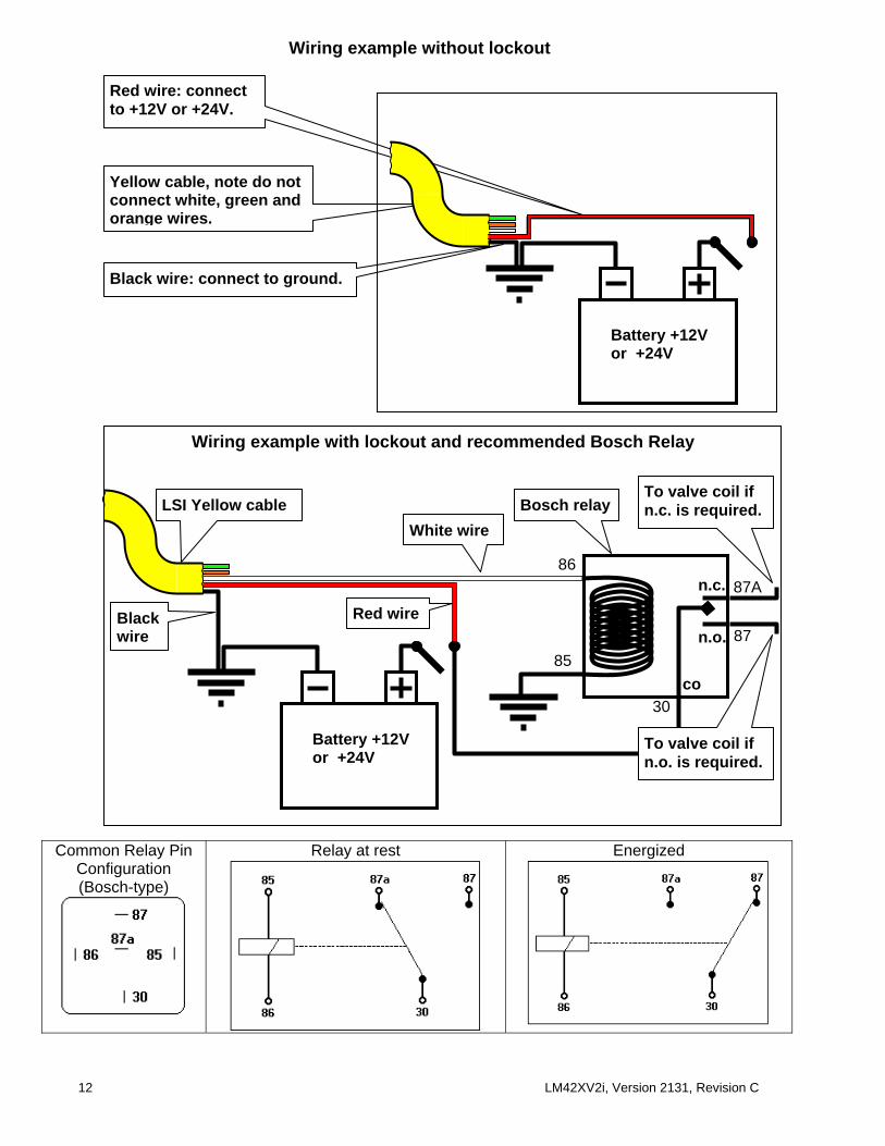
2.1.3 Power Supply and Lockout: The Yellow Power Cable WARNING! Do not connect the LS420/LS425V2i Display/Receiver to a positive body crane (crane structure connected to battery positive terminal). This will damage the display and void warranty. For installation of the LS420/LS425V2i to a positive body crane use the LS061 DC Power Conditioner to insulate the display from the effects of a positive body crane. Step 1) Connect the black wire (ground) to the negative terminal of the crane battery or the panel connection, alternatively bolt the black wire to the body of the machine with a ¼” or 5/16” bolt. The ground connection must be strong enough to sustain 3 Amp. Step 2) Connect the red wire to a fused accessory source, rated at least 3 Amps, that supplies +12 or +24 volts when the crane is on. The LS420/LS425V2i will automatically detect the volt-age level and adjust itself.
Step 3 – Optional Lockout) Connect the white wire to a Bosch relay coil. Connect the other ter-minal of the relay to the ground. When operating properly the white wire will energize at the bat-tery positive level.
Alternatively: the white wire may be connected directly to the lockout valve solenoid, with the other terminal of the solenoid connected to the ground.
Troubleshooting: if no voltage is present on the white wire remove the load connected to the lockout. Current over 1.5 Amps on the white wire triggers an auto re-settable fuse. Current flow will resume several seconds after the short-circuit is eliminated.
Step 4 – Optional Lockout) The green wire functions in the same way as the white wire, see step 3 above. Step 5) Do not connect the orange wire. Step 6) Connect the yellow cable to the LS420/LS425V2i. The connector is waterproof and well rated for external environments. Simply connect the cable to the display and gently tighten the nut. Do not put a kink in the yellow cable where it enters the connector; any bend in the cable at the base of the connec-tor must not be so severe as to break the in-ternal connections where the cable meets the connector.
(Black wire: negative (ground)
Red wire: +12 or 24 volts (crane power supply)
White wire: standard lockout
Green wire: for second lockout where required
Orange wire: do not connect.
Black wire Ground (Batt-)
Orange wire (Options)
Green wire Lockout 2
White wire Lockout 1
Red wire Battery V+ (12V to 24V)
12 LM42XV2i, Version 2131, Revision C
Common Relay Pin Configuration (Bosch-type)
Relay at rest Energized
Wiring example without lockout
Black wire: connect to ground.
Red wire: connect to +12V or +24V.
Yellow cable, note do not connect white, green and orange wires.
Battery +12V or +24V
Wiring example with lockout and recommended Bosch Relay
Battery +12V or +24V
n.c.
n.o.
co
Black wire
Red wire
White wire Bosch relay
To valve coil if n.c. is required. LSI Yellow cable
86
85
30
87A
87
To valve coil if n.o. is required.

LM42XV2i, Version 2131, Revision C 13
2.1.3.4 Lockout codes on white and green wires The LS420/LS425V2i includes the ability to generate two different kinds of alarm or lockout by assigning different triggers to the white and green wires of the yellow cable in the extended op-tions menu
Defining what triggers the lockout: Each alarm type could trigger a lockout if activated. See the list of alarm types in the table. Add lockout codes to create the trigger number. Enter the trigger number with limit+ and limit- on the white and green wire alarm pages. These pages are lo-cated in the extended options menu. Example: crane requires white wire to drop power on anti-two-block and overload signal.
Two-block: lockout code 128 Overload: lockout code 8 Total 136 So, in the extended options menus, under the white wire alarm sensor types, enter the value of 136.
Other typical values:
205 = A2B + Maximum Length + overload + max angle + max wind speed 34 = Maximum radius + minimum angle
2.1.3.5 Password Protection for Menu Access Note: this function is not available in the LS420V2iB and LS425V2iB handheld display/receivers. Three levels of access are present, administrator, user and no password. All menus available from the main screen could be individually set to request the user password. The ‘administrator password’ is required to access the password menu. Use this menu to change which other menu requires the ‘user password’. In the event of a lost of the administrator and the user password, call your LSI representative for a solution.
Step by step example on how to lock some menus
1) With the display powered up, press on Bypass & Limit- 2) Enter the administrator password (default = aza). Use tare to change the
flashing letter, and + & - to change it. Use hoist to go to next page. 3) You could change the administrator password to suite your need. Make sure
the service manager writes it down. A funny three letter word could be easier to remember than other combinations. Use hoist to change page.
4) You could change the operator password. Use hoist to change page. 5) For each of the next screen, protect or un-protect the appropriate menus. 6) Press bypass to exit.
See section Z.7 at the end of this manual for details.
White wire alarm Sensor types:205
Green wire alarm Sensor types: 34
Alarm type Lockout code
Two-Block 128 Maximum Length 64 Maximum Radius 32 Low Battery 16 Overload 8 Maximum Angle 4 Minimum Angle 2 Maximum Wind Speed 1

14 LM42XV2i, Version 2131, Revision C
2.2 LCxxx Load Cell Installation V1.2 The load cell antenna must not be in contact with metal. The load cell antenna must have a clear line of sight to the display unit. The load cell antenna must point to the left or to the right of the boom; it must not point directly to, or away from, the display unit. Step 1) The load cell may have two different pin and bushing sizes to fit different dead end and hook assembly requirements. Assembly of the load cell and adapter plates must be configured to the pin size required by the specific dead end or hook to which it is to be attached. In all cases, the brass bushings must be used where possible to adapt the holes in the load cell to the pins. Bushings must be secured with the hex screws provided, one on each side of the load cell. Step 2) A washer must be placed between adapter plate and cotter pin on each end of the pin that links the adapter plates to the load cell. Additional washers should be added as required to inhibit excessive lateral move-ment of load cell and adapter plates along the pin. If the dead end or hook to be connected to the adapter plates requires a larger opening, washers may be placed between the load cell and the adapter plates. Note: on the smaller of the two pins, space between the link and the plates should not exceed ¼” either side of the centred link regardless of washer place-ment. In all cases the washers must be placed
symmetrically such that the load cell is centred on the pins. Step 3) Once the pins are correctly placed and spaced, they must be secured with the cotter pins provided. Step 4) Every lift assembly must be verified by a qualified person before first use and pe-riodically thereafter, including before any new, difficult or otherwise different lift. WARNING! Capacity and safety factor for load cells and adapter plate assemblies are calculated for load along the intended axis of load (vertical with the assembly hanging free); side loading may cause load cell and adapter plate assembly to fail causing load to drop. Lifts must be rigged such that the load cell and adapter plate assembly hangs free and not be subjected to side loading.

LM42XV2i, Version 2131, Revision C 15
2.2.1 Load cell maintenance Reading Accuracy LSI Load cells are pre-calibrated at the factory. No “zeroing” or other calibration is required on installation. Each link is heat treated to age the steel and ensure stable readings for many years; load cells are individually temperature compensated to guarantee accuracy. Load cells are calibrated to indicate between 100% and 104% of their Safe Working Load (SWL). SAE J-159 4.2.1 recommends load indicating devices should show not less than 100% of the actual load and not more than 110% of the actual load.
Recommended maintenance: Weight accuracy LSI recommends testing the load cell every year for accuracy. The simplest way of testing a load cell is to lift at least two known weights. Note that a test weight should be known with an accuracy of ±1%. If the load cell is installed at the boom tip dead end, all additional equipment such as blocks, slings, sensors, etc. should also be known to an accuracy of ±1%. Determine the accuracy of the tested system with the following formula:
(based on SAE-J-159 7.3) The test loads must be significant relative to the load cell capacity. The minimum test weight is about 20% of the safe working load; a good test weight is greater than 50% of the SWL. For ex-ample, a 30,000 Lbs load cell on 4 parts of line has a SWL of 120,000 Lbs; the minimum test load in this case would be 24,000 lbs, a good test load would be 60,000 lbs or more.
Taking care of the load cell Batteries: at inspection time it is a good idea to change the batteries if they were not changed in the year, even if they are not indicating a low battery signal yet. The reason for it is because it is often easier to do it as a planned activity than in the field in a possibly remote area. Please consult section 3 of this manual for details. Inside the load cell transmitter, verify that no corrosion is visible on the battery holders. If some trace of corrosion is visible, gentle rub it and put a small amount, pea size, of dielectric grease1 on each battery holder posts to protect the contact. Mechanical stresses: verify dents or heavy scratches on the load cell side. The side of the load cell under the transmitter box is the most sensitive section. Engraving a number in this area will affect load cell accuracy and reliability. If the transmitter box has been hit and the box does not fit perfectly to the underlying link, please call LSI to have it repaired. Engraving on the transmit-ter box sides will not affect reading. Box water tightness: if the batteries are changed, make sure silicone has been used to seal the transmitter box. Antenna: small scratches on the antenna will not affect radio communications. A heavy bending of the antenna or bare sections on the wire may reduce the radio efficiency. It could then be wise to use one of the sent spare antennas. Transmitter box hex nuts damages: hex nuts are there to protect the antenna. If one or sev-eral hex nuts are scratched or cut, it will not affect the load cell readings on operation. Even if the load cells are made from heavy stainless steel, care should be taken when manipulating and working with the load cell. The weight measurement mechanism inside measures the tiny stretching of the steel to calculate the applied load. This means that heavy shock or clearly visi-ble scratches could affect accuracy.
1 Dow Corning dielectric grease #4

16 LM42XV2i, Version 2131, Revision C
2.3 LS010B Angle Sensor Installation The angle sensor antenna must not be in contact with metal. The angle sensor antenna must have a clear line of sight to the display unit. Warning! When welding the metal lugs to the boom the angle sensor must be kept well away from the weld site and any touching metal objects. The angle sensor is pre-calibrated at the factory; for correct installation it must be positioned carefully, then zeroed. The bracket has two boltholes, one of which is a curved slot for fine ad-justment. See the diagrams below for correct orientation. The angle sensor should be mounted on the left side or the right side (id#5000+) of the boom (as viewed from the cab) with the indica-tor light towards the boom tip.
Boom centerline.
Cabin
Boom The angle sensor is mounted with its hori-zontal axis parallel to the boom centerline.
Left side Front
Cabin
The angle sensor is mounted with its top/bottom axis within 15 degrees of vertical.
Front Front
Cabin
Boom
The angle sensor must not be mounted with its top/bottom axis more than 15 degrees from vertical.
Cabin
BoomA wedge can be used to mount the angle sensor with its top/bottom axis within 15 degrees of vertical.
Boom
The angle sensor is mounted with its hori-zontal axis parallel to the boom centerline.
Towards boom tip
Indicator light
Towards boom base

LM42XV2i, Version 2131, Revision C 17
Manual zeroing: the easiest method for two people
Mount the angle sensor with the indicator light pointing to the boom tip. Set the boom at a known angle such as 0 degrees, level. Finely adjust the position of the bolt in the curved slot until the angle sensor displays the correct value; allow the sensor a few seconds to ensure it has the most accurate reading. The system should then show the correct angle from zero to ninety degrees.
Angle sensor assisted zeroing: the easiest method for a single person
Step 1) Place the boom at zero degrees. Step 2) Mount the angle sensor with a bolt in the fixed position hole and tighten loosely. Step 3) Rotate the angle sensor to vertical and hold steady until the indicator light stops flashing for ten seconds. Rotate the angle sensor to horizontal (with the indicator light pointing to the boom tip). The indicator light will flash while changing from green to red de-pending on slight changes in the angle: this indicates that the angle sensor is in installation mode. The angle sensor should stay in installation mode for one or two minutes. Step 4) The colour of the light will help to place the angle sensor at zero degrees from horizontal. The goal is to position the angle sensor such that the indicator light is green without flashing: this indicates that zero has been obtained (the angle sensor is placed at 0 degrees, horizontal). Then place the second bolt in the curved slot and tighten both bolts securely. When the sensor angle is between 0.4 and 2 degrees, positive or negative, the light will flash green. Centered on 0 degrees, the light will be steady green. Everywhere else the light will flash red. If the indicator light goes out before zero has been obtained, repeat step 3. Zero could be hard to obtain; this is normal.
Indicator light in 'installation mode'
Angle Sensor at 30 degrees
Angle Sensor at 90 degrees

18 LM42XV2i, Version 2131, Revision C
2.4 LS050 Anti-two-block switch installation V2.0 The anti-two-block switch antenna must not be in contact with metal. The anti-two-block switch antenna must point to the left or to the right of the boom; it must not point directly to, or away from, the display unit. The anti-two-block switch antenna must have a clear line of sight to the display unit; in most cases this means mounting the sensor on the same side of the boom as the opera-tor's cab Before mounting any anti-two-block switch, verify that it is calibrated to the display unit. Switches shipped with display units are pre-calibrated in the factory. The display unit should go into alarm when the wire rope of a calibrated switch is pulled and released. Please note that the black travel clip must be removed to permit the switch to function. If a switch does not appear correctly calibrated to the display unit please follow the instructions in the calibration section (chapter 5) of this manual. Step 1) Remove the black travel clip.
• Leave the black travel clip at-tached to the sensor by the thin wire: it will be useful if the sensor is to be removed and stored in the fu-ture. • Releasing the wire rope will cause the alarm buzzer of the dis-play to which it is calibrated to sound. Pressing the bypass button of the display will silence the buzzer until the next two-block event or simulation.
Step 2) Position the sensor mounting bracket. To ensure that the sensor can pivot securely on the mounting bracket throughout the full range of boom angle, the mounting bracket must be positioned at a 30° from horizontal with the boom parallel to the ground and such that the locking pin of the mounting bracket points up. Bolt or weld securely.
a) A2B switch placement on a telescopic crane. For both live end and dead end mounting:
Up to 8” diameter
Mount bracket below and behind sheave center (see shaded region of diagram).
Depress the small button to release the locking mechanism and simultaneously…
…slide the locking ring back. The clip can now be opened to release the wire rope.
Pin up
30° from horizontal
LM42XV2i, Version 2131, Revision C 19
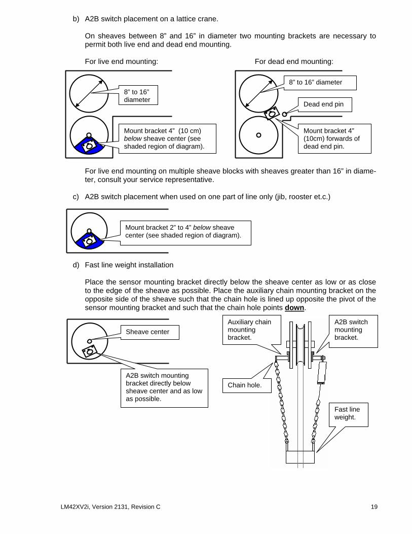
b) A2B switch placement on a lattice crane. On sheaves between 8” and 16” in diameter two mounting brackets are necessary to permit both live end and dead end mounting. For live end mounting: For dead end mounting:
For live end mounting on multiple sheave blocks with sheaves greater than 16” in diame-ter, consult your service representative.
c) A2B switch placement when used on one part of line only (jib, rooster et.c.)
d) Fast line weight installation Place the sensor mounting bracket directly below the sheave center as low or as close to the edge of the sheave as possible. Place the auxiliary chain mounting bracket on the opposite side of the sheave such that the chain hole is lined up opposite the pivot of the sensor mounting bracket and such that the chain hole points down.
8” to 16” diameter
Mount bracket 4” (10 cm) below sheave center (see shaded region of diagram).
8” to 16” diameter
Dead end pin
Mount bracket 4” (10cm) forwards of dead end pin.
Mount bracket 2” to 4” below sheave center (see shaded region of diagram).
A2B switch mounting bracket directly below sheave center and as low as possible.
Sheave center Auxiliary chain mounting bracket.
Chain hole.
Fast line weight.
A2B switch mounting bracket.

20 LM42XV2i, Version 2131, Revision C
Step 3) Test chain length.
i) At minimum boom angle, with no additional weight on the hook block and one part of line only, lift the boom just enough to have the hook block suspend and clear the sensor chain and weight. ii) Hoist slowly until the red two-block warning lights up and the buzzer sounds. Note the hoisting distance remaining; this distance must be great enough to allow the operator or the lockout system, if installed, to prevent a two-block event. If necessary, add lightweight chain between the sensor and weight to increase warning distance. If still insufficient, contact your service representative.
iii) Raise the boom to the maximum angle and repeat the procedure detailed in Step 2 very carefully. It will help to have a second person standing off to the side of the crane to closely monitor the hoisting distance from the hook block to the head sheave block. Verify that the warning distance is equal to or greater than that determined at the minimum boom angle. iv) Lower the boom until the weight height becomes visually clear to the operator. Repeat-edly create two-block, progressively hoisting faster to ensure that the warning and lockout (if installed) work within acceptable amount of time and distance. Increase the length of the small chain if needed.
Boom at minimum angle, two-block alarm triggered.
Hook block stops rising, two-block prevented with safety margin.
Boom at maximum angle, two-block alarm triggered.
Hook block stops rising, two-block prevented with safety margin.

LM42XV2i, Version 2131, Revision C 21
2.5 LS101 Length Sensor Cable Reel Installation Step 1) Install the reel on its solder tab on the main boom. The cable reel is usually installed on the main boom’s lower section on a clear area. Guides should be placed along the boom sections and a cable anchor near the boom head.
Step 2) Feed the cable through the cable guides and pull on it to attach it to the cable anchor. There should be minimal tension on the cable reel spring when the boom is fully retracted. Verify the boom length as shown on the appropriate operation screen of the dis-play unit. Please consult your Quick Reference Guide to find the length display for your specific LS420/LS425V2i system configuration. The boom length should represent the actual total boom length from the boom pin to the head sheave center, however, depending on the exact placement of the cable reel and cable anchor the displayed length may differ from the actual length. Note the differ-ence to the tenths of feet. Step 3) Adjust the length displayed: enter the sensor settings screen. To enter the sensor settings screens, hold the bypass button down continuously and press the tare button once. Release the bypass button when the screen offers the sensor set-ting menu. Press on the ‘Limit-’ button to access the sensor set-tings screen. Use hoist to find the length sensor position (a number between 1and 9). Continue to use hoist to find the "Trim" and "Scale" of the length sensor position number. Ex: if the sensor #3 is the length sensor, use hoist to find "#3 Trim: / Scale: ". Use the limit+ and limit– buttons to enter the difference noted above in tenths of feet. If the length displayed is 6 feet 6 inches too long, the trim should be reduced by 65. If displayed length is 5 feet short, add 50 to the trim value. When finished, press bypass to return to the main operation screen. For help with the buttons of the display please refer to the quick refer-ence guide or section 1.3 of the user manual. IMPORTANT! Step 4) Test: verify that the display correctly shows boom length when com-pletely retracted and when fully extended. It is safer to have someone helping to ensure that the reel has enough cable to reach full crane extension.
A:70.0º :22.8L:24.2 R: 8.2
Cable anchor
Cable guide
Cable reel
Boom base pin
Boom length: distance from boom base pin to head sheave center.
+ Radius Settings- Sensor Settings
#2 Trim : 125 Scale : 447
#2 Id= 4232 Length Sensor

22 LM42XV2i, Version 2131, Revision C

LM42XV2i, Version 2131, Revision C 23
Boom Length:150.0 + - change value
Jib Length: 50.0 + - change value
Jib Offset: 10.0 + - change value
+ Radius Settings- Sensor Settings
SlewOffset: 2.4+ - change value
2.6 Installation of Radius Calculation V1.0 Before proceeding with radius calibration: • Install the display unit (see section 2.1 of this manual). • Install the angle sensor (see section 2.3 of this manual) and verify the accuracy of its read-
ing. • For telescopic crane: install the length sensor (see section 2.5 of this manual). Make sure
the length is displayed properly for retracted and extended boom. • For lattice crane without a chart system: the boom length must be entered manually in the
display. This value must be adjusted every time the length of the lattice boom is changed. To access this page in the main operating pages, press on the Hoist button several times and one of the first 3 or 4 pages should offer to adjust the boom length. Note: the boom length adjustment screen will not be visible if the system is setup with a cable reel system because the cable reel will provide boom length automati-cally. The page will not be visible if the system has charts in it because the rigging menu will offer the available boom length (see section2.7)
• Enter the jib length if the working hoist is rigged to a jib. This value must be adjusted every time the length of the jib is changed.
• Enter the jib-offset angle if the working hoist is rigged to a jib. This value must be adjusted every time the angle of the jib is changed. Note: for accurate radius display when working with a luffing jib, an angle sensor must be installed on the luffing jib.
2.6.1 Radius Settings The boom length (lattice cranes only), jib length and jib offset angle must be correctly entered in the LS420/LS425V2i for accurate radius display. Furthermore, upon installation the LS420/LS425V2i must be calibrated for several crane specific angle and length parameters. De-fault values may have been programmed at the factory before shipping. Upon installation these parameters must be confirmed and accurate radius display verified. Step 1) To enter the radius settings screens, hold the bypass button down continuously and press the tare button once. Release the bypass button when the screen displays the radius and sensors settings. Press on the ‘+’ button to access the radius settings screen. Step 2) Determine the following measurements to within a tenth of a foot: slew offset, sheave head length and sheave radius. These measurements are described in sections 2.6.2 (lattice cranes) and 2.6.3 (hydrau-lic cranes). Verify that the radius parameters have been set correctly; the values may be ad-justed with the limit + and limit - buttons. Press the hoist button to proceed from one parame-ter to the next. Step 3) Test radius display. Compare the radius displayed with the actual radius at different lengths of boom extension and dif-ferent boom angles. If the radius displayed by the LS420/LS425V2i corresponds to the actual radius in all cases, the radius function is correctly calibrated. Be sure that all radius parameters have been carefully noted to facilitate re-calibration in the event of component or system up-grade, change, or re-installation. If there is a difference between displayed radius and actual radius that remains constant during changes in boom length and angle the slew offset can be adjusted to compensate (see step 2 above). E.g. if the radius displayed is always 2.3 feet longer than the actual radius subtract 2.3 from slew offset. If the radius displayed is still different from the actual radius proceed to section 2.6.4 of this manual (radius display trouble shooting).
1 25400 A:20.0L: 16.0 R: 7.5

24 LM42XV2i, Version 2131, Revision C
2.6.2 Radius Parameters for a Lattice Crane. The radius calculation parameters highlighted in green must be measured on the crane and set into the radius settings of the LS420/LS425V2i display unit.
The radius equation is roughly:
slew offset + boom length x cos(angle)
+ sheave length x sin(angle) + sheave radius
= radius
Jib offset angle.
Jib length.
Boom length: distance from boom base pin to head sheave center.
Crane center of rotation.
Slew offset: distance from boom base pin to crane center of rotation. If the boom base pin is behind the crane center of rotation this value must be negative.
(Your measurement)
Boom base pin.
Distance from head sheave center to jib mounting point. (Your measurement)
Head sheave radius. (Your measurement)
Sheave head length: distance from head sheave center to boom centerline. (Your measurement)
Head sheave.Jib mounting point.

LM42XV2i, Version 2131, Revision C 25
2.6.3 Radius Parameters for a Hydraulique Crane. The radius calculation parameters in green must be measured on the crane and set into the radius settings in the LS420/LS425V2i display.
The radius equation is roughly: slew offset
+ boom length x cos(angle) + sheave head lenPr x sin(angle)
+ sheave radius = radius
The slew offset is the distance between the boom heel pin and the center of ro-tation. If the boom pin is behind the center of rotation, the value must be negative.
(Your measurement)
Sheave radius.
(Your measurement)
Crane center of rotation
Boom heel pin
Boom length: distance from boom base pin to head sheave center.
The sheave head length is the distance be-tween the center of the lower sheave and the projection of the boom heel pin along the boom. This is called the “Sh.Len Pr:” pa-rameter in the radius settings.
(Your measurement)
Boom heel pin

26 LM42XV2i, Version 2131, Revision C
Boom Deflc: 0.0+ - change value
2.6.4 Radius Display Troubleshooting For accurate radius calculation the actual boom length and angle, and the jib length and angle must be correctly displayed by the LS420/LS425V2i and the calibration parameters described in section 2.6.1 must be correctly measured and entered in the radius settings of the LS420/LS425V2i display. Before proceeding with troubleshooting confirm that the radius calibra-tion procedure described in section 2.6.1 has been followed correctly. The most common rea-son for error is caused by incorrect slew offset compensation. If the difference between the ra-dius displayed and the actual radius remains constant through all boom angles and boom lengths the slew offset should be adjusted accordingly. Some booms bend significantly with a load on the hook, thus reducing effective radius. Boom deflection can be verified if the displayed radius is equal to the actual radius with the boom at 0° and at 90° but greater at a boom angle of 45° (boom deflection is greatest at 45°). Furthermore, the effect of boom deflection is greater when the boom is longer. To compensate for boom de-flection, adjust the boom deflection value in the radius settings of the LS420/LS425V2i display. Follow the steps below to determine the appropriate boom deflection compensation value.
Step 1) Raise the boom to 45° with a known load. Step 2) Compare the radius displayed with the actual radius. Change the boom deflection compensation value and again compare the radius dis-played with the actual radius. Adjust the boom deflection value until the radius displayed equals the actual radius. Tip: with the boom at 45° and the maximum load on the hoist, the boom deflection compensation value should equal the difference in feet between the radius displayed and the actual radius. With the boom at 45° and half the maximum load on the hoist, the boom deflection compensation value should equal twice the difference in feet be-tween the radius displayed and the actual radius. Etc.
Note: the "No Ld Defl" (no load deflection) value permits compensation for booms that deflect significantly under their own weight, even with no load on the hoist. This value should only be adjusted in consultation with LSI. For any information contact LSI: see page 2 of this manual.

LM42XV2i, Version 2131, Revision C 27
2.6.5 Advanced Radius Settings (Reference) On most cranes, the parameters described in the sections 2.6.2 to 2.6.4 should be sufficient to provide accurate radius. On complex cranes with chart system, engineer will usually have set the appropriate information on the crane structure. This is complemental information.
Lattice Extension Offset Angle (LExt Off)
Boom Length
Extensions, two possibilities: 1) Manual Length: offset always zero degrees. 2) Lattice Extension Length: offset angle must be set too. Parameter name in radius settings menu: (LExt Len)
Boom Top Length (BTop Len)
Boom Top Offset (BTop Off)
With the most common Sheave Head: (Sh.Len Pr) distance perpendicular to boom centerline: arrow D1 (Sh.Len Pl), distance parallel to last boom section = 0
Special top sheaves such as rooster sheaves: (Sh.Len Pr) distance perpendicular to boom centerline: dimension D2 (Sh.Len Pl), distance parallel to last boom section: dimension D3
D2
D3
Slew Offset.
Boom top Length & offset BTop Len BTop Off
Lattice Extension Length & offset LExt Len: LExt Off
Main Boom
Jib Mounting Point Parallel & perpendicular JibMntPtPl JibMntPtPr
Fixed Jib Length & Offset Jib Length Jib Offset
Luffing Jib Length (center sheave to center sheave) LJib Length
Boom Heel Pin
Angle sensor
Angle sensor
Boom length in-cludes boom top
Lattice Extension Length (LExt Len)
D1

28 LM42XV2i, Version 2131, Revision C
2.7 LS425V2i Chart System Capacity Chart Selection (Rigging a Sheave) Principles of operation: The LS425V2i has been custom programmed with specific crane capacity charts. The LS425V2i displays working load limit (WLL), based on chart selected and angle/radius information re-ceived from the boom-mounted sensors. For accurate WLL display, the correct chart must be selected. Furthermore, the display may be calibrated for several load cells, e.g. the main hoist, auxiliary hoist, a “whip-line” etc. Because hoists can be rigged to different sheaves and each sheave may have different dimensions and mounting point characteristics, the system must be programmed to know what load cell is where in order to display the correct WLL for each load cell. The LS425V2i defines 4 sheaves, numbered 1 to 4. Usually, the first load cell calibrated to the sensor settings would be the main hoist load cell, and is usually set as the sheave #1. The auxil-iary would be set on sheave number 2, and so on… How to – the “Chart Wizard”:
1. Press Bypass and Limit+ simultaneously to enter the chart wizard. 2. Press Hoist to rig. 3. Select the sheave number with Limit+ and Limit-. Press on Hoist to continue. 4. Select the capacity chart with Limit+ and Limit-. 5. Press Hoist to confirm selection. Other chart options could
be present. 6. Verify system limits – press Limit-.
Select Sheave Number: 3

LM42XV2i, Version 2131, Revision C 29
2.8 Portable Battery Operated Display: LS420V2iB/LS425V2iB The portable battery display LS420/LS425V2iB has an internal battery pack composed of 5 NiMH AA batteries. A charge cable with wall plug adapter is supplied. To recharge internal battery pack, connect the charge cable to the display for about 5 hours. The batteries use NiMH technology, similar to common cell phone and digital camera batteries. They can be charged on a regular basis, even if not fully discharged.
Charge time 5 hours Battery operation 8 hours Number of charge cycles Over 1000 cycles Technology AA size NiMH (similar to digital cameras) Battery pack replacements Contact your LSI representative
Turn the display on with the toggle switch on the right side of the display. When fully charged, the display will operate for 8 consecutive hours or more. Battery life is con-served when the display is off.
Charge cable with wall plug adapter
Transformer cable must be connected to the display to
charge it

30 LM42XV2i, Version 2131, Revision C
2.9 Palm Interface Kit Set-Up Kit includes:
• Palm • Charge cable • Palm-USB cable • CDRom “Desktop Software & Manual”
The Palm must be charged prior to, or during, set-up. The purpose of this section is to explain:
a) LS425V2i internal datalogger content (black box): how to access 2.9.1 How to install Palm software to a desktop pc. 2.9.4 How to upload data logger files from LS425V2i to the Palm. 2.9.5 How to transfer files from the Palm to the desktop pc.
b) Updating a LS420V2i or LS425V2i firmware: installation and update process 2.9.1 How to install Palm software to a desktop pc. 2.9.2 How to transfer files from a desktop pc to the Palm. 2.9.3 How to download firmware from the Palm to the LS425V2i.
2.9.1 Install Palm Software to a Desktop PC 1. Insert the CDRom identified Desktop Software & manual in the PC CDRom drive; instal-
lation will begin automatically. This software is also available on the internet at Palm’s web site: http://www.palmone.com/us/support/downloads/win_desktop.html
2. The software should be installed in the default directory: C:\Program Files\Palm. 3. Follow the installation wizard step by step. 4. When asked to create a new account, select “Yes” but leave the name in the entry text
box blank. The installation wizard will automatically create a folder with the name of the Palm or other compatible device. For example: Zire21 (with no space).
5. When prompted to reboot the pc select “Yes”. 6. In Windows Explorer go to C:\Program Files\palmOne and start HotSync.exe. A small
icon will appear in the Windows tray bar to indicate that HotSync is installed on your desktop pc; this software is use to establish communication and synchronize data be-tween the Palm and the pc.
2.9.2 Transfer Files from the PC to the Palm Two types of files can be sent to the Palm:
• LSI Firmware, Charts and Configuration updates for the LS425V2i, identified by a .PDB suffix.
• LSI Firmware and LSI Datalogger software, identified by the .PRC suffix. These files are required in the Palm to enable communication with an LS420/Ls420V2i display.
A. Send an LS425V2i firmware update to the Palm:
1. Connect the Palm to the pc using the Palm-USB cable. 2. In Windows Explorer double click (or right click) on files
with the PDB extension to add them to the Palm installation list. Windows will automatically start a PalmOne files list; this corresponds to the files that can be sent to the Palm the next time the Palm will e synchronized.
3. Synchronization Palm-PC. On the Palm, start HotSync: press the star icon on the Palm. Alternatively press the house icon, select “all” from the drop down menu in the upper right hand corner, select HotSync from the Palm “home” menu and then press the center

LM42XV2i, Version 2131, Revision C 31
of the HotSync icon. Once started HotSync will connect the Palm with the pc and update files from each.
2.9.3 Transfer Firmware Updates from the Palm to the LS425V2I
1. Start the LSI Firmware Palm Software: on the Palm,
press the house icon to go to the “home” menu, select “all” from the drop down menu in the upper right hand corner, select “LSI Firmware”.
2. On the Palm, select the firmware file to send in Firmwares file list.
3. Correctly align the infrared ports of the Palm and the LS425V2i at a distance less than 3 feet.
4. The display should be powered up. 5. On the Palm, press “send”. 6. If a valid firmware is already inside the LS425V2i, the Palm application will ask if the
user wants to keep the actual LS425V2i Configuration Page. Select Yes to keep the configuration and No to have the default configuration. We recommend clicking on ‘No’ to reset the display to default settings unless you know the update is minor. (See section 2.9.6 for more on the configuration.)
7. If the transfer fails or does not start: power down and power up the display while keeping the test button pressed. It will enter a fail safe mode which will allow the update to be accomplished.
8. The LS425V2i will display “Transferring”. 9. Note: If the option to keep the configuration is
selected, the Palm Software will first receive the actual configuration and then send the firmware.
10. When the transfer is complete the Palm generates a short musical alarm; the LS425V2i displays the version identification of the LS425V2i firmware now installed.
2.9.4 Transfer Data Logger Files from LS425V2i to the Palm 1. Start the LSI Datalogger Palm software on the Palm. If it
is not installed yet, follow the procedure in step 2.9.2. Press the house icon to go to the “home” menu, select “all” from the drop down menu in the upper right hand corner, select “LSI Datalogger”.
2. Correctly align the infrared ports of the Palm and the LS425V2i at a distance less than 3 feet.
3. On the Palm, press “receive”. 4. The LS425V2I will display “Transferring”. 5. When the transfer is complete the Palm generates a
short musical alarm and displays the uploaded file name in the LSI Datalogger file list.
6. If the transfer fails or does not start: power down and power up the display while keeping the test button pressed. It will enter a fail safe mode which will allow the update to be accomplished.

32 LM42XV2i, Version 2131, Revision C
2.9.5 Transfer Data Logger Files from the Palm to the Desktop PC 1. Connect the Palm to the pc using the Palm-USB cable. 2. On the Palm, start HotSync: press the star icon on the Palm. Alternatively press the
house icon, select “all” from the drop down menu in the upper right hand corner, select HotSync from the Palm “home” menu and then press the center of the HotSync icon. Once started HotSync will connect the Palm with the pc and update files from each. Data logger files will be transferred to the following directory of the pc:
C:\Program Files\Palm\LSI\Backup 3. The Data Logger Viewer Windows application may now be used to read the file.
2.9.6 LS425V2i Configuration Page The LSI Firmware Palm Software can conserve the actual (old) system configuration when up-dating a firmware. This means that system parameters entered to the LS425V2i menus will not be erased (e.g. radius parameters and sensor ids). When this option is selected the Palm Pilot retrieves the configuration from the LS425V2i and saves it before sending the new firmware. If a problem occurs during the firmware update, the saved configuration file will be displayed in the LSI Firmware Charts/Config list. It’s then possible to send the configuration back to the LS425V2i by selecting the file in the list and by pressing the send button of the LSI Firmware Palm Software. In case of difficulties, or if strange result occurs, do the update and select the ‘No’ option when asked to keep current configuration. This will reset all sensors, radius information, to the default settings of this firmware.
2.9.7 Transfer Configuration Files from LS425V2i to the Palm 3 Start the LSI Firmware Palm Software: on the Palm, press the house icon to go to the
“home” menu, select “all” from the drop down menu in the upper right hand corner, se-lect “LSI Firmware”.
4 On the Palm, press “GetCfg” 5 Correctly align the infrared ports of the Palm and the LS425V2I. 6 The LS425V2i will display “Transferring”. 7 When the transfer is complete the Palm generates a short musical alarm and a file with
the name CONFIG# is added to the Charts/Config list.

LM42XV2i, Version 2131, Revision C 33
Variation 5% + - change value
2.10 Data Logger Recording Set the mode for data logger function in the extended options menu. The six modes available are described below. All alerts are recorded by the data logger regardless of the mode selected.
2.10.1 All Data Mode All communications between a display and its sensors are recorded.
2.10.2 User Input Mode The status of all sensors is recorded on demand. This option is available on request only; it re-quires a custom hardware modification to the display and a normally open push button must be installed on the orange wire of the LB003 yellow power supply cable.
2.10.3 Automatic Peak Mode The datalogger analyzes the measured weight and records the peak value only. When “Automatic Peak” is selected in the extended options menu four other pages in the menu are made available: “Threshold1”, “Threshold2”, “Threshold3” and “Threshold4”. Adjust the weight thresholds for up to four load sensors here. If the crane has only one load cell, only “Threshold1” must be adjusted. How it works? The automatic peak detection finds the highest load measured between the moment the load exceeds the set threshold (the load clears the ground or is taken by the load cell) and the mo-ment load returns below the set threshold (the load is returned to the ground or removed from the load cell). The threshold should be a value greater than the weight of hook, block and rig-ging, and lower than the weight of the load that must be detected. Example: With a hook block weighing 230 lbs, the threshold could be set to 400 lbs. The system will detect the highest load measured between the moment the load is greater than 400 lbs and the moment the load it falls under 400 lbs. Note: if units are in Kg, the threshold will be in Kg.
2.10.4 Automatic Variation Mode Load is recorded when it varies by more than the set variation threshold from the last recorded value. The difference between the current load and the last datalogger recorded load is re-calculated several times per second. With a variation threshold of 5% the datalogger will record an event every time the load changes by 5% or more. The variation threshold is adjustable in page four in the extended options menu; by default it is set to 5%.
2.10.5 AutoRecord 1 min The datalogger records all current sensor readings once every minute.
2.10.6 AutoRecord 10min The datalogger records all current sensor readings once every 10 minutes.
Adjustable “Pick threshold”
0 Lbs
Weight
Time
“Peak weight”
3
2
1
Example of a pick

34 LM42XV2i, Version 2131, Revision C
2.11 Data Logger Viewer (Option) 2.11.1 Description The Data logger viewer software is an application that is used to display a data logger file on a PC. For instructions on how to transfer datalogger files from the LS425V2i to the PC via the Palm, see the LS420 – palm/pc interface guide. The Data logger viewer software opens the Palm database file, converts it into a text (binary) file and displays the contents. The Export to Excel feature exports the log into an excel workbook.
2.11.2 Installation Three files are needed to install the DataloggerViewer application: DataloggerViewer.CAB, setup.exe, and SETUP.LST To start the installation process, run the setup.exe program and follow the installation wizard through the steps of the installation.
2.11.3 Operation First, run the installation program if not already installed. In the upper left corner there are four icons.
The first is to open a file, the second is to save a file under a new name. The third is to print a file and the fourth is to export a file to Microsoft excel. Microsoft Excel must be installed on the PC to use this option. The first three icons can be found in the file menu and the fourth one in the tool menu. The view menu is to select the toolbar that you want to view.
To view a datalogger log, click on File->Open and open a Palm Database File (.pdb) that was previously retrieved from the Palm device. Note that only .pdb files generated by the LS420 Download Palm software are supported.
Note: The .pdb file you have just downloaded onto the PC with your Palm will probably be in the C:\Palm\$UserName$\Backup directory. The name of the file will look like this:
LSI_08_13_2004_15_31_48.PDB A Text file can also be opened. This is a .pdb file that was converted and saved under a tab-delimited format using the DataloggerViewer application.

LM42XV2i, Version 2131, Revision C 35
The DataloggerViewer application now displays the datalogger log information. To export the log to excel, click on the Export to Excel toolbar button or menu.
2.11.4 Log File Information The following information is related to the sensor that has generated the event:
Time: The time that the event was generated. Date: The date that the event was generated. Crane Battery Voltage: Voltage of the crane at the moment of the event. Event: The type of event logged.
Two-block event Overload event Length limit event Angle low limit event Angle high limit event Radius High limit event Wind limit event Sensor Low battery event Bypass key activated event Crane Start-up event Value: Value of the sensor that has generated the event. Sensor Battery Value: The percentage of the battery remaining of the sensor that has gener-ated the event. Radio power: The radio power of the sensor that has generated the event. Sensor Code: The type of sensor that has generated the event: Load Cell sensor, Load Pin sensor, Anti-two-block sensor, Wind sensor, Length sensor Radius sensor, Angle sensor, Sum sensor The following information is related to all the other sensor in the system and is the same for the eight sensor remaining: Sensor Code #1 to 8: The type of sensor. Sensor Status #1 to 8: The sensor was active or inactive. Value #1 to 8: The value of the sensor

36 LM42XV2i, Version 2131, Revision C
2.12 LS020 Wireless Wind Speed Sensor Installation Includes:
1. Wind speed sensor/transmitter assembly 2. Mounting rod 3. Mounting screw 4. Mounting screw washers (2)
Installation
1. Unscrew the mounting rod from the wind speed sensor transmit-ter assembly.
2. Select the welding point for the mounting rod. The mounting rod must be installed on the same side of the boom as the cabin mounted display, perpendicular to the boom at the highest point possible. Notes:
a. The sensor/transmitter assembly must swing free of any obstruction,
b. No object should interfere with the wind cups, c. There must be a clear and unobstructed line of sight between the sen-
sor/transmitter antenna and the cabin mounted display unit, d. The transmitter antenna must not contact any metal object.
WARNING! Do not weld in proximity to LSI sensor/transmitters. 3. Weld the mounting rod to the boom at the selected point. 4. Screw the sensor/transmitter assembly to the mounting rod with the mounting screw.
Note that washers should be screwed one to each side of the brass bushing of the sen-sor/transmitter assembly.
Mounting rod
LS020 wind speed sensor/transmitter
Boom tip
Weld point
Sheave head
Boom tip
LS020 speed wind sensor/ transmitter

LM42XV2i, Version 2131, Revision C 37
↑
2. Single part block
LP011/LP015 load pin
Crosby wedge socket
Cotter pin
LP011/LP015 load pin
Pigtail
AA10K11 LINE PULL
↓
1. Boom tip
2.13 LP011 & LP015 Wireless Load Pin Installation Includes:
5. LP011/LP015 load pin 6. LB501 jumper cable, 20” 7. LS001A load transmitter
WARNING! Do not pull on the load pin by the pigtail. WARNING! Do not weld in proximity to LSI sensor/transmitters. Installation:
A. The Load pin: 1. The load pin mounts to the boom tip or block by replacing the pin of the Crosby
wedge socket. 2. The load pin is directional and must be oriented correctly to indicate load accu-
rately; the pin must be installed such that the bracket embraces the wedge socket thus preventing pin rotation. Note: for boom tip installation the lot number can be read right side up and the “line pull” arrow points down to-wards the block. For single part block installation the lot number can be read upside down and the “line pull” arrow points up towards the boom tip.
3. The load pin must be secured in place with a cotter pin or other suitable keeper device.
B. The load pin transmitter:
1. The load pin transmitter mounts on the two solder tabs provided. 2. The load pin transmitter should be placed such that:
i. The load pin and transmitter pigtails connect easily without stretching or kinking under all boom angles and working conditions. Note that the jumper cable may be used between the load pin and transmitter pigtails to increase transmitter placement options.
ii. There is a direct unobstructed line of sight from the transmitter to the dis-play/receiver (note: this may not be required on cranes with a maximum boom length less than 100’).
iii. The transmitter antenna contacts no metal object.

38 LM42XV2i, Version 2131, Revision C
Chapter 3: Changing Batteries 3.1 Changing Load Sensor Batteries V1.4
DO NOT change load sensor batteries without first reading these in-structions.
Many operators damage their load sensors with incorrect battery changing pro-
cedures.
ALWAYS replace all three batteries of a load sensor at the same time. Replacing just one or two batteries will cause the unchanged batteries to reverse polarity, dramati-cally reducing the efficiency and life of the new batteries. This means all batteries will need to be changed again within the next couple of days or even hours… ONLY use an RTV non-corrosive silicone (available where auto-parts are sold) to re-seal the box after batteries have been changed. Many silicones give off corrosive gasses that destroy the battery contacts; this renders the sensor useless. ALWAYS remove the battery closest to the indicator light first, by applying pressure to the NEGATIVE pole ( – ) only. When metal (i.e. a screwdriver) touches the steel box and any battery pole other than the negative pole of the battery closest to the indica-tor light, a short is caused which may burn the sensor's internal circuits. FOLLOW all the instructions detailed below. Carefully following every step described below is the quickest, easiest way to successfully change batteries without damaging the load sensor. • Batteries should be changed when reduced to 10 – 20 % of full charge. • The following items are necessary to successfully change the batteries of the load sen-
sor: a) Three new, high quality, alkaline “C” cell batteries (e.g. Duracell Ultra or Energizer E2). b) A Phillips head screwdriver c) A small knife d) A flat head screwdriver e) Optionally, a very small flat head screwdriver f) An RTV non-corrosive silicone (available where auto parts are sold)
Notes For CSA Class 1, Division 2 Rated Equipment
WARNING: Understand manual before operation. WARNING: Replace batteries only in area known to be non-hazardous. Use only Varta UNIVERSAL Alka-line batteries model number 4014 or Duracell Procell model number PC1400 batteries. WARNING: SUBSTITUTION OF COMPONENTS MAY IMPAIR INTRINSIC SAFETY WARNING: SUBSTITUTION OF COMPONENTS MAY IMPAIR SUITABILITY FOR CLASS I, DIVISION 2 For sensors: Use "T4" temperature code, and for LS420 use "T4A".
Step 1. Remove the load sensor from the crane Step 2. Clean off dust and grime. During the following operations the interior of the battery box must be protected from dirt and humidity at all times.

LM42XV2i, Version 2131, Revision C 39
Do not unscrew the white nylon hex bolt of the antenna. Do not unscrew the four round topped hex bolts Do not cut any wires Step 3. Unscrew the two Phillips head screws about ¼ inch. Do
not fully unscrew or remove these screws to avoid destroying the seal in which they are set.
Step 4. Carefully cut the silicone seal all around the base of the
box where it meets the link. Step 5. Carefully separate the box from the link by inserting a
flat head screwdriver in the notch where the box meets the link and turning. Do not damage the wires that run between the link and the box.
Step 6. Gently pull
on the connecting wires to disconnect the plug in the bat-tery box.
Avoid all contact with the tiny white inter-rupter switches.
Step 7. To remove the batteries, always remove the
battery closest to the indicator light first, the mid-dle battery second, and the battery furthest from the indicator LED last. The batteries can easily be re-moved by hand. Gently apply pressure in the direc-tion of the negative pole while lifting out the positive pole.
Tip: Alternative method: use a very small, flat head screwdriver. Gently place the tip of the screwdriver against the top of the negative pole of the battery closest to the indicator light and, using the side of the box for support, lift the battery up until it can be grasped and removed by hand.
Indicator light
+
The battery closest to the indicator light is removed first.
The screwdriver is applied to the negative contact only.
+
+
Notch

40 LM42XV2i, Version 2131, Revision C
Step 8. To install the three fresh, top quality, alkaline “C” cells the positive/negative alignment of the batteries as in-dicated on the interior walls of the box must be respected. Insert the negative pole first. Once the negative pole is halfway in, gentle pressure in the direction of the negative pole will allow the positive end of the battery to be pushed in. Do not force more than is necessary. Upon installa-tion of the third battery, the indicator LED will light briefly, indicating correct placement of the batteries
Step 9. Clean the leading edges of the box and
the surface of the load cell where contact is to be made.
Step 10. Apply the RTV non-corrosive silicone to the link to create a joint of 1/8th inch. Step 11. Reconnect the wire connector. Only one orientation is possible. When correct ori-
entation is achieved, press down to mate securely.
Once again the small flat head screwdriver may help: use extreme caution!
Step 12. Reposition the box over the link. Avoid pinching the connecting wire between the box and the link or between the batteries and the link. Verify that the silicone forms an ef-fective seal all around the joint between box and link.
Step 13. Secure the box to the link by tightening the two Phillips head screws. Step 14. Clean off excess silicone. Step 15. If battery replacement has been successful, the “Low Batt” icon of the cabin-
mounted display will no longer be lit. Use of the test function will confirm new battery status.
Step 16. Reinstall load sensor.

LM42XV2i, Version 2131, Revision C 41
3.2 Changing Angle Sensor Batteries V1.4
DO NOT change angle or wind sensor batteries without first reading these in-structions.
Many operators of LS401, 420, 425 and 2002 systems damage their angle and wind sensors
with incorrect battery changing procedures.
ALWAYS replace all three batteries of an angle or wind sensor at the same time. Re-placing just one or two batteries will cause the unchanged batteries to reverse polar-ity. This means that all batteries will need to be changed again within the next couple of days or even hours… ONLY use an RTV non-corrosive silicone (available where auto parts are sold) to re-seal the box after batteries have been changed. Many silicones give off corrosive gasses that destroy the battery contacts; this renders the sensor useless. ALWAYS remove the battery closest to the indicator light first, by applying pressure to the NEGATIVE pole ( – ) only. When metal (i.e. a screwdriver) touches the steel box and any battery pole other than the negative pole of the battery closest to the indica-tor light, a short is caused which may burn the sensor's internal circuits. FOLLOW all the instructions detailed below. Carefully following every step described below is the quickest, easiest way to successfully change batteries without damaging the angle or wind sensor.
• Batteries should be changed when reduced to 10 – 20 % of full charge. • An angle sensor must be re-calibrated after this procedure. Follow instructions in the angle
sensor installation chapter of this manual. • The following items are necessary to successfully change angle or wind sensor batteries:
a) Three new, high quality, alkaline “C” cell batteries (e.g. Duracell Ultra or Energizer E2). b) A Phillips head screwdriver c) A small knife d) A flat head screwdriver e) Optionally, a very small flat head screwdriver f) An RTV non-corrosive silicone (available where auto parts are sold)
Notes For CSA Class 1, Division 2 Rated Equipment WARNING: Understand manual before operation. WARNING: Replace batteries only in area known to be non-hazardous. Use only Varta UNIVERSAL Alka-line batteries model number 4014 or Duracell Procell model number PC1400 batteries. WARNING: SUBSTITUTION OF COMPONENTS MAY IMPAIR INTRINSIC SAFETY WARNING: SUBSTITUTION OF COMPONENTS MAY IMPAIR SUITABILITY FOR CLASS I, DIVISION 2 For sensors: Use "T4" temperature code, and for LS420 use "T4A".
Step 1. Remove the angle or wind sensor from the crane. Step 2. Clean off dust and grime. During the following operations the interior of the angle or wind sensor box must be protected from dirt and humidity at all times.

42 LM42XV2i, Version 2131, Revision C
Do not unscrew the white nylon hex bolt of the antenna. Do not unscrew the four round topped hex bolts Step 3. Unscrew the two Phillips head screws about ¼ inch. Do not fully unscrew or remove
these screws to avoid destroying the seal in which they are set. Step 4. Carefully cut the silicone seal all around the base of the box where it meets the
mounting plate. Step 5. Carefully separate the box from the mounting plate by inserting a flat head screw-
driver in the notch where the box meets the link and turning.
Avoid all contact with the tiny white interrupter switches. Step 6. Remove the battery closest to the indicator
light first, the middle battery second, and the battery furthest from the indicator LED last. The batteries can easily be removed by hand. Gently apply pressure in the direction of the negative pole while lifting out the positive pole.
Tip: Alternative method: use a very small, flat head screwdriver. Gently place the tip of the screwdriver against the top of the negative pole of the battery closest to the indicator light and, using the side of the box for support, lift the battery up until it can be grasped and removed by hand.
Indicator light
+
The battery closest to the indicator light is removed first.
The screwdriver is applied to the negative contact only.
+
+
Notch

LM42XV2i, Version 2131, Revision C 43
Step 7. Install the three fresh, top quality, alkaline “C” cells; the positive/negative alignment of the batteries must be re-spected as indicated on the interior walls of the box. Insert the negative pole first, keeping the battery as parallel to its final position as possible. Once the negative pole is half-way in, gentle pressure in the direction of the negative pole will allow the positive end of the battery to be pushed in. Do not force more than is necessary. Upon installation of the third battery, the indicator light will flash briefly, indicat-ing correct battery placement.
Step 8. Clean the leading edges of the sensor box and the surface of the mounting plate
where contact is to be made. Step 9. Apply the RTV non-corrosive silicone to the mounting plate to create a 1/8th inch
joint. Step 10. Reposition the sensor box over the mounting plate. Verify that the silicone forms
an effective seal all around the joint between box and plate. Step 11. Secure the box to the mounting plate by tightening the two Phillips head screws. Step 12. Clean off excess silicone. Step 13. If battery replacement has been successful, the “Low Batt” icon of the cabin-
mounted display will no longer be lit. Use of the test function will confirm new battery status.
Step 14. Reinstall the angle or wind sensor; calibrate an angle sensor following the installa-
tion procedure outlined in the angle sensor installation chapter of this manual.

44 LM42XV2i, Version 2131, Revision C
3.3 Changing Anti-two-block Batteries V1.5
ALWAYS replace all four batteries of a two-block sensor at the same time. Replacing just one, two or three batteries will cause the un-changed batteries to reverse polarity. This means that all batteries will need to be changed again within the next couple of days or even hours…
• Batteries should be changed when reduced to 10 – 20 % of full charge.
• The following items are necessary to successfully change the batteries of the anti-two-block:
a) A monkey wrench. b) Four new, high-quality, alkaline “C”-cell batteries (Duracell Ultra or Energizer E2 rec-
ommended).
Notes For CSA Class 1, Division 2 Rated Equipment WARNING: Understand manual before operation. WARNING: Replace batteries only in area known to be non-hazardous. Use only Varta UNIVERSAL Alka-line batteries model number 4014 or Duracell Procell model number PC1400 batteries. WARNING: SUBSTITUTION OF COMPONENTS MAY IMPAIR INTRINSIC SAFETY WARNING: SUBSTITUTION OF COMPONENTS MAY IMPAIR SUITABILITY FOR CLASS I, DIVISION 2 For sensors: Use "T4" temperature code, and for LS420 use "T4A".
Step 1) Remove the anti-two-block from the crane and clean off dust and grime. During the following operations the interior of the anti-two-block must be protected from dirt and humidity at all times. Do not unscrew the white nylon hex bolt of the antenna. Do not unscrew the small screw to the left of the antenna. Do not remove the small black plastic plug on the bottom of the anti-two-block. Step 2) Place the anti-two-block on the edge of flat surface. Using a monkey wrench, partly unscrew (about a half-inch) the large white nylon hex bolt through which the wire rope passes. Step 3) Carefully remove the plunger assembly, without separating it from the cover, and place it on a clean and dry sur-face. Step 4) The four batteries will easily slide out. Step 5) Insert the four fresh, clean, top quality, alkaline “C” cells according to +/- schema printed on the back of the sensor.

LM42XV2i, Version 2131, Revision C 45
Step 6) Replace the plunger assembly. Correctly align the bot-tom cover before screwing in the white nylon hex bolt through which the wire rope passes. This hex bolt should be well tight-ened with the monkey wrench. If battery replacement has been successful the LED on the bot-tom of the sensor will flash red when the wire rope is pulled and the “Low Batt” icon of the cabin-mounted display will no longer be lit. Use the test function of the cabin-mounted display unit to confirm new battery status. Step 7) Reinstall the anti-two-block.

46 LM42XV2i, Version 2131, Revision C
Chapter 4: Replacing Antennae 4.1 Replacing Sensor/Transmitter Antennae • There are two types of sensor antennae:
1. Part number TA010, load/angle/wind sensor antenna: a green tape identifies those made in the spring of 2002 and thereafter. The TA010 is used on the following sensor transmitters: all load sensors, all angle sensors, all wind sensors and the LS005 anti-two-block transmit-ter (wired to mechanical switch). The TA010 is re-placeable.
2. Part number TA011, two-block sensor antenna: a blue tape identifies those made in the spring of 2002 and thereafter. The TA011 is used on LS050 and LS050B anti-two-block switch/transmitters only. The TA011 is replaceable. The antennae of two-block sensors made before February 16th, 2002 are not replaceable in the field: please contact your service representative.
Note: the TA010 and TA011 are not inter-changeable. • Slightly damaged antennae (bent, sheathing scratched,
plastic head cap missing etc.) should not be replaced unless otherwise identified as prevent-ing proper sensor function. Heavily damaged antennae (ripped out, sheared off, wire ex-posed and fraying etc.) should be replaced to ensure communication between the sensor and the cabin mounted display unit.
• The following items are necessary to successfully replace the antenna of a load or angle
sensor: a) a new antenna, of the appropriate type (load/angle/wind sensor or two-block sensor),
with white nylon hex bolt b) a small pair of pliers c) an electrical insulating compound
Step 1. Place the crane, boom, jib or ball hook such that the sensor is safely accessible. This procedure may be followed without removing the sensor from the crane only if it is safe to do so; avoiding removal and reinstallation procedures may save time. If removed, an angle sensor must be re-calibrated during reinstallation for correct angle display (see the angle sensor installation section of the user manual). During this procedure the interior of the sensor must be protected from dust, grime and water at all times. If it rains during the procedure an umbrella or other suitable means of protection should be used. Step 2. Clean dust, grime and water from the sensor. Step 3. Identify the short black whip antenna and the
white hex bolt securing it. Step 4. Inspect the antenna for signs of obvious
physical damage. Step 5. Carefully unscrew the white nylon hex bolt
completely and slide it up the antenna.
Anti-two-block an-tenna with identifying blue strip
Load/ angle/
wind an-tenna
with identi-fying
green strip

LM42XV2i, Version 2131, Revision C 47
Step 6. Grip the antenna by the base of the black
plastic sheathing and pull it straight out of the hole in which it is seated. Place the old antenna aside.
Step 7. Slide the white nylon hex bolt to the middle of
the length of the new antenna. Step 8. Coat the exposed metal foot of the new an-
tenna with an electrical insulating compound by care-fully inserting it in the mouth of the compound tube.
Step 9. Hold the new antenna by the black plastic sheathing and guide it through the hole in the sensor box. Carefully seat the antenna in its mating connector. When the antenna is correctly seated, pulling on it will be met with light resistance.
Step 10. Carefully re-thread, screw-in and
tighten the white nylon hex bolt to secure the antenna in place.
Step 11. Reinstall the sensor if necessary (if removed from the boom or jib, an angle sensor
will require re-calibration during the installation procedure, see the angle sensor installation section of the user manual).
Step 12. Verify that the sensor functions properly.
White nylon hex bolt
Antenna
Sensor box
Antenna receptacle

48 LM42XV2i, Version 2131, Revision C
Chapter 5: Adding and Removing Sensors • If in difficulty, disconnect and reconnect the yellow cable of the LS420/LS425, then press
the test button to verify all calibrated sensors. If in serious difficulty, simply start over by erasing all sensors from the system (section 5.2), then re-entering them one by one (sec-tion 5.1).
• Correctly set the parts of line, tare and all applicable limits for any newly added sensor. The buzzer will usually sound when a sensor is added until the appropriate limits have been set; this is to ensure that the limits will be verified. While adjusting limits or parts of line, press the limit + and the limit - buttons simultaneously to set a default value.
5.1 How To Add A Sensor to the LS420/LS425. 5.1.1 The Sensor Settings Screens Step 1) Determine the ID (a number between 0 and 60000) of the sensor to be added; the ID is engraved on the sensor. The LS420/LS425 uses the ID to identify the sensor. Sensors should be installed on the crane before engaging in the calibration procedure. Sensors must transmit to be identified by the LS420/LS425; lifting a load with a load cell or changing the angle of an angle sensor will ensure immediate transmission. Step 2) To enter the sensor settings screens, hold the bypass button down continuously and press the tare button once. Release the bypass button when the screen displays: Press on the ‘-’ button to access the sensor settings screen. Step 3) Press the hoist button until the second line of the screen displays “No Sensor”, which is a free slot in the list of 9 possible sensors. Use the limit + and limit - buttons to set the ID number of the sensor to be added. Use the parts button to select the type of sensor to be added. Every time the parts button is pressed, the type of sensors will cycle through a list like this one: { No Sensor, Load Cell, Load Pin, Anti-Two-Block, Wind Sensor, Length Sensor, Ra-dius Sensor, Sum Load Cell, Rope Payout, Angle Sensor, etc… }. When sensors are added or removed, the display will automatically try to find a set of pages to show all the relevant informa-tion in the main operating pages. The ‘configuration number’ selects a set of page and is de-scribed in section 5.3. Press the bypass button to exit the manual calibration mode at any time.
5.2 How to Remove A Sensor from the LS420/LS425 Step 1) To enter the sensor settings screens, hold the bypass button down continuously and press the tare button once. Release the bypass button when the screen displays: Press on the ‘-’ button to access the sensor settings screen. Step 2) Press the hoist button until the sensor to be removed is shown with the correct ID and sensor type (Load, Angle etc.). Press the tare button to remove the sensor. The display will show "ID = 0" on the first line and "No Sensor" on the second line. Press the bypass button to exit the manual calibration mode at any time.
+ Radius Settings- Sensor Settings
+ Radius Settings- Sensor Settings

LM42XV2i, Version 2131, Revision C 49
5.3 Sensor Configuration of the LS420/LS425 When a sensor is added or removed, the system configuration number is automatically ad-justed. The configuration number identifies the page set used for information display in the op-eration mode. If necessary the configuration number can be adjusted manually: hold bypass down continuously and press tare once. Release bypass when the screen displays "Radius Setting + / Sensor Setting - ". Press limit - to select sensor settings. Scroll through the pages with hoist until the screen displays "Select Config / Config= xx Ok". Use limit + and limit - to select the appropriate configuration number. Press bypass to exit the manual calibration mode at any time.
LS420 mode x32 x16 x8 x4 Length Radius Wind Angle Load Comment 1 0 0 0 0 1 1 load sensor 2 0 0 0 0 2 2 load sensors 3 0 0 0 0 3 3 load sensors 4 0 0 0 1 0 1 angle sensor 5 0 0 0 1 1 1 load, 1 angle 6 0 0 0 1 2 2 load, 1 angle 7 0 0 0 1 3 3 load, 1 angle 8 0 0 1 0 0 1 wind sensor 9 0 0 1 0 1 1 wind 1 load sensor
10 0 0 1 0 2 1 wind 2 load sensors 12 0 0 1 1 0 1 angle, 1 wind 13 0 0 1 1 1 1 load, 1 angle, 1 wind 14 0 0 1 1 2 2 load, 1 angle, 1 wind 15 2 wind speed, 1 angle sensor 16 0 0 2 0 0 2 wind speed sensors 21 0 1 0 1 1 1 load, 1 angle, 1 radius 22 0 1 0 1 2 2 load, 1 angle, 1 radius 29 0 1 1 1 1 1 load, 1 angle, 1 wind, 1 radius 30 0 1 1 1 2 2 load, 1 angle, 1 wind, 1 radius 27 Heel & List angle sensors, wind on page 2 28 Heel & List angle sensors 31 3 load cells; page 1 displays A, B, C and weight units 32 8 load sensors, A through H 33 For systems with only anti-two-block 34 1 load + 2 angle 35 1 load + 2 angle + 1 radius 36 1 load + 2 angle + 1 radius + 1 wind 37 Special chart system 38 2 load + 1 summation. Page 1= sum. Page 2=2 loads 39 2 load + 1 angle + 1 summation 40 2 load + 1 summation. Page 1=2 loads. Page 2= sum. 41 2 load + 2 angle + 1 wind 42 2 load + 2 angle + 1 radius + length 43 2 load + 2 angle + 1 radius + 1 wind 44 3 loads, 2 angle & radius 45 4 load, A, B, C & D 46 4 load + 1 summation 47 4 load + 1 wind 48 2 load + 1 angle + 1 radius, show aux on page1 49 2 load + 1 angle + 1 radius,show 2 loads on page1 50 Page1=load, angle & radius. Page 2 = wind 51 Page1=load, angle & radius. P2=Heel&List P3 = wind 52 1 1 0 1 0 1 angle, 1 radius, 1 length 53 1 1 0 1 1 1 load, 1 angle, 1 radius, 1 length 54 1 1 0 1 2 2 load, 1 angle, 1 radius, 1 length 61 1 1 1 1 1 1 load, 1 angle, 1 radius, 1 length, 1 wind 62 1 1 1 1 2 2 load, 1 angle, 1 radius, 1 length, 1 wind
Several special configuration numbers must be entered manually to the select configu-ration page. System will return to default configuration on every entry in sensor settings.

50 LM42XV2i, Version 2131, Revision C
* Note: multiple hoist cranes only require one “radius sensor”. Radius ID is not used, it could be set at any value without affecting the system.
LS425 mode
Configuration number
Hydraulic / Lattice Length Radius Wind Angle Load
64 H 1 1 0 1 1 65 L 0 1 0 1 1 66 H 1 1 0 1 2 67 L 0 1 0 1 2 68 H 1 1 0 2 2 69 L 0 1 0 2 2 70 H 1 1 1 1 1 71 L 0 1 1 1 1 72 H 1 1 1 1 2 73 L 0 1 1 1 2 74 H 1 1 1 2 2 75 L 0 1 1 2 2
When in LS425 mode, the configuration number corresponding to the sensor configuration cali-brated will be selected automatically.

LM42XV2i, Version 2131, Revision C 51
Chapter 6: Troubleshooting 1.0 Troubleshooting Index 6.1 The Display Doesn't Light Up 6.2 The Lock-out Doesn't Engage 6.3 The Display Unit Is Always In 2 Block Alarm Mode 6.4 The Display Unit Is Always In Alarm Mode, the main hoist green light is flashing 6.5 The Display Unit Is Always In Overload Alarm Mode 6.6 The Display Unit Is Always In Limit Alarm Mode 6.7 The Display Unit Is Always In Wind Speed Alarm Mode 6.8 Radio Communication Problem

52 LM42XV2i, Version 2131, Revision C
6.1 The Display Unit Does Not Light Up
Verify the connections of the blackwire, the red wire and, if appro-
priate, the white wire of the yellowcable as described in section 2.1
of the Universal User Manual.
Yes
No
Yes
Verify the voltage on the black wire,the red wire and, if appropriate
according to the specifications inthe user manual, the white wire of
the yellow cable.
No
Yes
No
Disconnect theyellow cable fromthe display unitand reconnect it
carefully
No
No
Yes
Yes
Is therea change in the
display?
Please call your servicerepresentative
The display won't light up
Press "Test" button
Is there a badconnection? reconnect properly
Is therea change in the
display?
Press "Test" buttonto verify communica-tion and battery sta-tus of all sensors.
Is thevoltage on the wires
equal to that of the cranebattery?
Verify the crane battery. Verify thecrane fuse. Verify the crane
accessory switch if applicable.
Please call your servicerepresentative
Press "Test" buttonto verify communica-tion and battery sta-tus of all sensors.
Is therea change in the
display?

LM42XV2i, Version 2131, Revision C 53
6.2 The Lock-out doesn't Engage or is Always Engaged
Disconnect the yellowcable from the displayunit and reconnect it
carefully.
Wait 30 seconds and measure the voltage on the white wire.
Is the voltage on thewhite wire equal to thatof the crane battery?
Please call yourservice representative
Verify the connection of thewhite wire of the yellow cable
No
No
Disconnect the white wire from the lock-out circuit
Place the cranein non-lock-out
condition
Yes
Is thedisplay in lock-outor alarm mode?
Verify the voltage on the white wire of the yellow cable.
Is the voltage on thewhite wire equal to that of the
crane battery?
No
No
Is the voltage on thewhite wire equal to that of the
crane battery?
Wait 30 secondsand measure the
voltage on thewhite wire.
No
No
The display should befine, verify lock-out
functionYes
Measure currentdrawn on whitewire by lock-out
system. Refer tolock-out section inthe user manual.
YesDoes lock-out system
draw more than 1A on thewhite wire?
Is thevoltage on the
white wire equal to thatof the crane
battery?
Measure the voltageon the white wire.
Reconnect the white wire to the lock-out circuit
No
Yes
No
Install a relay asexplained in the
lock-out section ofthe user manual.
Yes
Yes
Carefully create a lock-out using an A2B switch. If there isno A2B switch in communication with the display lock-out
may be created by temporarily adjusting a load or angle limit.
Measure the voltage on the white wire of the yellow cable.
Is the voltageon the white wire
equal to zero?
Everything seemsfine, return any limits
you may have changedto their appropriatevalues and verifylock-out function
Disconnect the white wirefrom the lock-out circuit
Wait 30 seconds andmeasure the voltage on
the white wire.
Is the voltageon the white wire
equal to zero?
Yes
No
Lock-out coilsmay be connected tothe positive batteryvoltage of the crane
instead of the negativeground. Verify andrefer to the lock-outsection of the user
manual.Call customer service
No
Yes
Yes
Is there any flashinggreen lights on the
display?
Verify all sensors ID,wait 4 minute, still
flashing?
See section 6.8 on radiocommunication
Yes

54 LM42XV2i, Version 2131, Revision C
6.3 The Display Unit Is Always In Alarm Mode, The "2 Block" warning light is on 6.4 The Display Unit Is Always In Alarm Mode, the main hoist green light is flashing
Yes
Place all A2Bswitches in
safe condition.
No
The anti-two-block switchappears to be working properly,
please refer to the lockoutsection of the user manual.
Yes
Press the "Test" button.
Are A2Bbatteries low? No
Take the A2Bswitch off thecable. Pullon the wire
rope.
Does the redlight on the A2B switchflash after pulling on the
wire rope?
Yes
Thereappears to be acommunicationproblem, see
diagnosticmode p. ?
Yes
The batteriesneed changing.
Refer to thechanging anti-two-
block batteriessection of theuser manual.
No
Reinstall the batteries, carefully inspectthe battery and plunger cavities for
infiltration of water or dirt. Refer to thechanging batteries section of the user
manual.
Pull on the wire rope.
Does the red light onthe A2B switch flash after pulling on
the wire rope?
Yes
Reinstall the A2Bswitch on the cable.Verify A2B function.
No
Please call yourservice representative
Is the"2 Block"warninglight still
on?
Yes
The load cell failsafewarning is on. On
startup this is normal asthe load cell may take up
to fifteen minutes tocommunicate its batterystatus to the display unit,
until which time thefailsafe warning will
sound.
Are load cell batteries low?
Verify battery installation orchange batteries if necessary,
see the changing load cellbatteries of the user manual.
Yes
No
Verifycommunication
between the loadcell and the display
unit (follow theprocedure).
Press the "Test" button to verify battery status.
The display is always in alarm mode,the "2 Block" warning light is on?
The display is always in alarm mode,the main hoist green light is on?

LM42XV2i, Version 2131, Revision C 55
6.5 The Display Unit Is Always In Alarm Mode, the Load warning light is on
If "Hoist" button green light is on press the "Hoist" button until it goes off.
Press the "Parts" button to verify that the parts of lines is consistent with actualcable configuration. Refer to the "Parts" button section in the user manual.
If the "Tare" button light is on, press the "Tare" button once to disable the tare function
Press either the "Limit +" or the "Limit -" button to see the limit programmed for the hoist.Verify thatthe limit programmed is consistent with the crane capacity in its present configuration.
Remove weightfrom load cell.
The display isalways in alarm
mode: the "Load"warning light
is on.
If there is an auxilliary load cell press the "Hoist" button until the "Hoist" button light is on. Repeatthe previous three steps to verify the parts of lines, tare and laod limit for the auxilliary hoist.
Does theload displayed nowcorrespond with the
weight on theload cell?
No
Yes
Is theoverload alarm
still on?
Please call yourservice representative
Yes
Everything seems to befunctioning normally.No
Verifycommunication
between load cell anddisplay unit (follow
procedure on page x)then return here.
Verify overloadalarm function.
Doesthe overload
alarm now functionproperly?
Yes
No Press "Test" to verifyloadcell batteries.
Verify battery installation. Please pay specialattention to avoid infiltration of water or dirt and to
ensure that the load cell wires are properly connecteand not severed. Change the batteries if necessar
Verify proper loadcell function.
Does theload displayed nowcorrespond with the
weight on theload cell?
Is theoverload alarm
still on?
Please call yourservice representative
Everything seems to befunctioning normally.
Please callyour service
representative
Yes
No
No
Yes

56 LM42XV2i, Version 2131, Revision C
6.6 The Display Unit Is Always In Alarm Mode, the Limit+ or Limit- warning light is flashing
The display is alwaysin alarm mode: the"Limit +" warninglight is flashing.
Press the "Hoist" button untilthe boom angle is displayed.
Does the angleshown correspond toactual boom angle.
The maximum angle limitappears to be reached: pressthe "Limit +" button to verify
that this limit has beencorrectly set, refer to the
adjusting angle limit section ofthe user manual.
Press the "Bypass" button toreturn to the main operatingscreen. Press the "Hoist"
button until the boom angle isshown.
Verify the angle sensorinstallation. Reinstall or
recalibrate if necessary, seethe angle sensor installationsection of the user manual.
Press the "Test" button toverify battery status.
Is theboom angle
shown less than themaximum angle
limit set?
Is the"Limit +" warning light
still flashing?
The maximumangle limit warning
appears to befunctioning normally:
refer to the usermanual for a
description of thiswarning.
Please contact yourservice representative.
Yes
No
Yes
Yes
Are anglesensor batteries
low?
Verify battery installationor change batteries ifnecessary, see the
changing angle sensorbatteries of the user
manual.
Yes
No
Verifycommunicationbetween angle
sensor and displayunit (Section 6.4).
No
No
The display is alwaysin alarm mode: the
"Limit -" warning lightis flashing.
Press the "Hoist" button untilthe boom angle is displayed.
Does the angleshown correspond toactual boom angle.
The minimum angle limitappears to be reached: press
the "Limit -" button to verifythat this limit has been
correctly set, refer to theadjusting angle limit section
of the user manual.
Press the "Bypass" button toreturn to the main operatingscreen. Press the "Hoist"button until the boom angle
is shown.
Is theboom angle
shown greater than themaximum angle
limit set?
Is the"Limit -" warning light still
flashing?
The minimumangle limit warning
appears to befunctioning normally:
refer to the usermanual for a
description of thiswarning. Please contact your
service representative.
Yes
No
Yes
Yes
No
No

LM42XV2i, Version 2131, Revision C 57
6.7 The Display Unit Is Always In Alarm Mode, the wind speed alarm message is flashing
The windspeed alarm
message is alwaysflashing
Visually inspect the windspeed sensor for
physical damage. Verifyproper installation, referto wind speed sensor
installation instructions.
Does thewind speed shown
correspond to actualwind speed?
Is windspeed greater than
set wind speedlimit?
Yes
Yes
No
No
The maximumwind speed warning
appears to befunctioning normally:
refer to the usermanual for a
description of thiswarning.
Press the "Test" buttonto verify battery status.
Are windspeed sensorbatteries low?
Verify battery installationor change batteries ifnecessary, see the
changing wind speedsensor batteries of the
user manual.
Yes
No
Verifycommunicationbetween wind
speed sensor anddisplay unit
(Section 6.4).

58 LM42XV2i, Version 2131, Revision C
6.8 Radio Communication Problem
Radio communication between sensor(s) and cabin mounted display unit faulty.
Press the "Test" button and verify the sensor ID #. The ID # for each sensor can be found on the sensor itself or on any invoiceor shipping document for that sensor. Note that the ID # of older A2B switches is indicated on the A2B switch body in binaryform. The binary to decimel conversion procedure is detailed in the A2B calibration mode section of the distributor manual.
Does thedisplay unit indicatethe correct ID # for
the sensor?
Yes
No
Does thedisplay unit indicate"0" or "5535" as the
sensor ID #?
Yes
The sensor chip's memory has been erased, please refer tothe technical manual or contact your service representative.
No
Visually inspect the antennas of the sensorand the cabin mounted display unit.
Is there a clear anddirect line of sight between the sensor antenna and the
antenna of the display unit?
Yes
Are both the sensor andthe display unit antennas clear (6") of all contact with any
metal object at all times?
Yes
Are both the sensorand the display unit antennas complete and
undamaged?
Reinstall either the display unit, thesensor or both such that there is a clearand direct line of sight between the two
antennas at all times.
No
Reinstall either the display unit orthe sensor such that both antennas are
clear of all contact with any metalincluding cables, chains, the boom,
or the cabin itself.
No
No
A damaged antenna may need replacing.To replace the antenna of a load cell, an anglesensor or a wind speed sensor please see theappropriate section of the user manual. If an
A2B switch antenna needs to be replaced pleasecontact your service representative.
Yes
If it is safe to do so, verify that the sensor is operational by observing its red LED during a changein condition (change the boom angle for an angle sensor, pull the wire whip for an A2B switch,
change the load for a load cell, change the apparent wind speed for a wind sensor).
If either the sensor or the display unit hasrecently been installed or replaced, the displayunit may require recalibration. If display unit's
memory has been affected by a lightning strike orother electrical event it may need reprogramming.
Refer to the technical manual or contact yourservice representative.
Does thesensor appearoperational?
No
Verify sensor batteries, reinstall or replace ifnecessary, see the appropriate section of theuser manual. Check for possible interferencesfrom a defective fan or air conditioning in the
cab. Verify the frequency range of any wirelessdevice used in the cab.
Does thesensor appearoperational?
There appears to be aproblem with the sensor,
please contact your servicerepresentative.
No

LM42XV2i, Version 2131, Revision C 59
6.9 Palm Pilot Communication Issues Difficulties copying a file to a Palm Pilot when using several Palms with the same PC. 1. Transfer a firmware to a Palm
a. Click on the mouse right-button over the file in an Explorer window. Then select “Send To”… and “Palm Quick Install”. See the pic-ture below.
b. Or… double-click on the firmware received in an email. 2) Usually a window will pop up to confirm the addition of this file to the list of files to be transferred to a Palm. Verify the “User” in this window. Two or more “User”s may be configured to the PC. How to verify how much memory is left on a Palm Pilot. 1) Power up the Palm. With the plastic pen, press on the Home icon on the lower left side of the screen to see the time of day on the upper left. 2) Press on the time of day, a menu should pop up, press on <Info…> in this menu. A page will show how much free memory is available on the Palm. Example; 1.1M means 1.1 megabytes, equates to 1100 Kb (Kilo-bytes). Each LS420 firmware uses about 140Kb of mem-ory. If there is not enough memory left, verify if some ap-plications or datalogger files could be removed. Note: A firmware with crane capacity charts may require more memory. What to do if the palm doesn’t respond. If the Palm doesn’t appear to respond to commands, or if problems occurr during a transfer operation, the Palm can be reset by pressing the reset button on the back. All ap-plications will then restart; data should not be lost.
Example of having two usernames on the same PC. One is “LSI” and the other one is “lsi”. This could be really confusing and must be verified if you have problems copying to your Palm Pilot.
How to free up memory 1) Power up the Palm. With the plastic
pen, press on the Home icon on the lower left side of the screen until an icon called “LS420 Download” is visi-ble.
2) Press on the LS420Download icon. A list of available files will be displayed.
3) Press on the file to be deleted 4) Press on the delete button 5) The system will ask confirmation be-
fore deleting the file

60 LM42XV2i, Version 2131, Revision C
Chapter 7: Contact Information
USA Corporate Office: 9223 Solon, Suite A Houston, TX 77064 Toll Free Phone: (888) 819 4355 Direct Phone: (281) 664 1330 Toll Free Fax: (888) 238 4099 Direct Fax: (281) 664 1390
Email: [email protected] Dubai Corporate Office: Y02 Saif Zone P.O. Box 7976 Sharjah, United Arab Emirates Tel.: +971 6 557 3814 Fax: +971 6 557 3815
Email: [email protected] Canadian Corporate Office: 4495 boul. Wilfrid-Hamel, bureau 110 Québec QC G1P 2J7 Direct Phone: (418) 650 2330 Direct Fax: (418) 650 3340
Email: [email protected] Technical Support 9223 Solon Rd., Suite A Houston TX 77064 Toll Free Phone: (888) 819 4355 Direct Phone: (281) 664 1330 Toll Free Fax: (888) 238 4099 Direct Fax: (281) 664 1390
Email: [email protected]

LM42XV2i, Version 2131, Revision C 61
LSI PRODUCT WARRANTY 2006/05/26
LIMITED WARRANTY:
LOAD SYSTEMS INTERNATIONAL INC. (“LSI”) warrants that its products (the “Products”), for a pe-riod of two (2) years after delivery of such Products (the “Warranty Period”), when installed and used in ac-cordance with specifications described in user manuals, technical materials and any related writings published by LSI with respect with such Products, will be free from defects in materials and workmanship. During the Warranty Period, LSI or its designated service representative shall repair, or at its option, replace any Product that is confirmed to be defective by LSI in accordance with the warranty services procedures described below.
WARRANTY SERVICES PROCEDURES:
In order to benefit of the above-mentioned warranty, the purchaser shall notify LSI’s customer service or LSI’s authorized distributor or representative originally responsible for the sale of the Products within the Warranty Period in order to obtain a Return Authorization Number. A proof of purchase of the Product, such as an invoice or a receipt certifying the validity of this warranty, shall be presented in order to obtain warranty services. In any event, even if a Return Authorization Number is provided to purchaser, LSI re-serves the right to inspect the damaged Product or part before the final decision of repairing or replacing the defective Product or part.
The defective Product or part shall be returned to LSI or its designated service representative, accompanied by the Return Authorization Number with prepaid shipping charges at the address mentioned below. The purchaser must insure the shipment or accept the risk of loss or damage during the shipment. Purchaser shall also pay any tariff or duty applicable to the return of defective part or Product. LSI will, at its option, repair or replace the Product or part returned to LSI or to its designated service representative. LSI owns all parts removed from a repaired Product. If LSI repairs a Product, its warranty is not extended. If LSI replaces a Product, the replaced Product is warrantied for the remainder of the original term or sixty (60) days, which-ever is longer.
LSI will pay transportation costs of replacement or repaired parts to the destination in Canada and the conti-nental United States of America. LSI will not pay any transportation costs of replacement or repaired parts to destination outside of Canada and the continental United States of America which costs shall be for the pur-chaser’s account.
Parts with a Return Authorization Number can be sent to the following location:
From the USA and Mexico:
Receiving Department Tel.: (281) 664-1330 Fax: (281) 664-1390 LSI – U.S. Warehouse 9223 Solon Rd., Ste. A Houston, TX 77064-1238 United States
From Canada:
Warranty & Repair Tel.: (418) 650-2330 Fax: (418) 650-3340 Load Systems International Inc. 4495 boul. Wilfrid-Hamel, Bureau 110 Québec, QC G1P-2J7 Canada

62 LM42XV2i, Version 2131, Revision C
EXCLUSION OF OTHER WARRANTIES
The above warranty is the sole warranty applicable and there are no express, legal or implied warranties or conditions in relation to any Products including any implied warranty or condition of merchantability, non-infringement or fitness for a particular purpose and those otherwise arising by statute or otherwise in law or from a course of dealing or usage of trade, which are expressly disclaimed. No oral or written information or advice given by LSI or its employees or representatives shall create a warranty or condition or in any way in-crease the scope of LSI’s obligation. LSI does not warrant that the business results obtained from the use of the Products will be appropriate or adequate for the purchaser.
EXCLUSION
The above-mentioned warranty does not cover and shall not apply to:
• any shipping charges to LSI or an designated service representative as well as the technician out-of-pocket expenses including traveling, lodging and meal expenses, if any;
• the damages caused during the transport or the move of the Products;
• damages caused by accidents, abuse, misuse, a force majeure or external cause;
• Products altered, modified or repaired not expressly authorized by LSI;
• any cost, damage or expenses for field labor or any other expenses related to or arising from the re-placement of defective parts.
• Products used for pile-driving, wire rope activated clamshell or dragline applications. If pur-chaser uses the Products for pile-driving, wire rope activated clamshell or dragline applica-tion, the warranty will automatically become null and void.
LIMITATION OF LIABILITY
To the maximum extent permitted by applicable law, in no event will LSI be liable to the purchaser or any third party for any indirect, special, consequential, incidental or exemplary damages whatsoever, including but not limited to loss or revenue or profit, lost or damaged data, business interruption or any other pecuniary loss whether based in contract, tort or other causes of action, even if LSI has been advised of the possibility of such damages. In any event, the total liability of LSI arising from any cause of action or claim whatsoever, whether (1) in contract, (2) in tort (including negligence, whether sole, joint, contributory, concurrent or oth-erwise, but not including intentional, reckless or wanton tort), (3) under strict liability, (4) under any environ-mental or antipollution law or regulation, (5) connected with any toxic or hazardous substance or constituent, (6) arising out of any representation or instruction, or under any warranty, (7) or otherwise, arising out of, connected with, or resulting from the design, manufacture, sale, resale, delivery, repair, replacement or use of Products or the furnishing of any service shall in no event exceed the price allocable to and paid to LSI for the individual unit of Products or service or part thereof which gives rise to the cause of action or claim.
RECOMMENDED PRACTICE
LSI recommends careful consideration of the following factors when specifying and installing the Products. Before installing a Product, the Installation, Operation, and Maintenance instructions provided with the unit must be read and understood.

LM42XV2i, Version 2131, Revision C 63
INSTRUCTIONS TO THE USER This equipment has been tested and found to comply with the limits for a class B digital device, pursuant to part 15 of the FCC Rules. These limits are designed to provide reasonable protec-tion against harmful interference in a residential installation. This equipment generates, uses, and can radiate radio frequency energy and if not installed and used in accordance with the in-structions, may cause harmful interference to radio communications. However, there is no guar-antee that interference will not occur in a particular installation. If this equipment does cause harmful interference to radio or television reception, which can be determined by turning the equipment off and on, the user is encouraged to try to correct the interference by one or more of the following measures:
• Reorient or relocate the receiving antenna. • Increase the separation between the equipment and receiver. • Connect the equipment into an outlet on a circuit different from that to which the receiver
is connected. • Consult the dealer or an experienced radio/TV technician for help.
In order to maintain compliance with FCC regulations, shielded cables must be used with this equipment. Operation with non-approved equipment or unshielded cables is likely to result in interference to radio and TV reception. The user is cautioned that changes and modifications made to the equipment without the approval of manufacturer could void the user's authority to operate this equipment.

64 LM42XV2i, Version 2131, Revision C
Z. LS42xV2i Menu Reference Section
Z.1. Sensor Settings: press bypass + tare simultaneously, and then press limit-. Position of sensors is irrelevant, they could be mixed anywhere between the nine slots avail-able. This page show an example, sensors may vary from system to system. The only position related setting is this: the first sensor of any given type in this list should be a main hoist sensor, if applicable. Ex: if two load cells are set, the first one should go on the main boom and the sec-ond on the auxiliary hoist.
# Screen Details 1 Sensor Settings
Scroll W/Hoist Press Hoist button to go to next page
2 #1 Id= 5255 Load cell
Set the ID to the actual load cell transmitter ID. For load pins, dynamometers or other weighting device need-ing calibration, use the ‘Load Pin’ sensor, which will allow in-display calibration. In this menu, the Parts button could be used to change the sensor type. In case of error, press on Tare to erase the current sensor and start from scratch. The sensor programmed here will be represented by the left side green light under the load icon, under letter M for Main.
3 #2 Id= 4855 Angle Sensor
Set the ID to the actual number engraved on the angle or angle-length transmitter.
4 #3 Id= 4855 Length
Set the ID to the actual angle-length transmitter ID. 2xADC sensor no longer exists. See the TB-LS425V2I-2xADC-2004-11-19.
5 #4 Id= 0 Radius Sensor
This is required to provide radius calculations and user settable radius limits. The ID number is not used and could be kept at zero.
6 #5 Id= 5524 A2B switch
Other sensors or A2B switches
7 #6 Id= 4220 Wind Speed
... 10 #9 Id= 0
No Sensor
11 Select Config Config= 70 Ok
The configuration is the set of pages on the main user screen. The number is calculated automatically every time a sensor is added or removed, even for LS425.
The display will exit here if there is no length, angle or load pin sensors.
12 #1 Trim : 0 Scale : 464
Adjustment on the sensor #1. If the sensor #1 is a load pin, this adjustment will be for the load pin. If the sensor #1 is a cable reel, this will adjust the displayed length in tenths(1/10) of feet. Press on tare to switch between edit-ing the trim and editing the scale factors. See the additional technical notes in Section 4 below.

LM42XV2i, Version 2131, Revision C 65
13 #2 Trim : 0 Scale : 1024
If the second sensor is a cable reel, this trim and scale will be for the cable reel. If the second sensor is an angle sen-sor, then the trim will allow adjustment of the angle value. Trimming the angle value is helpful when the cable reel is welded at an angle, the trim could cancel this angle.
14 #3 Trim : 0 Scale : 1024
If the third sensor is a cable reel as in the example in pre-vious page, this trim and scale could be adjusted to get the best accuracy.
See the additional technical notes in Section 4 below.
Adjusting Scale and Trim Values Note: Trim Length: this is usually the only value that requires an adjustment on installation. Sensor types Scale Trim Load cells No adjustments available (load cells are
always pre-calibrated from factory) No adjustments available (load cells are always pre-calibrated from factory)
Load pins
Adjustable. Default: 1024 = no scale Displayed=ReceivedVal*Scale/1024+Trim
Adjustable.
Angle sensor Angle sensors are pre-calibrated from factory, only the trim could be adjusted to compensate for small installation angles. DisplayedAngle=SensorAngle+TrimAngle
Angle trim is available and could be used to compensate installation offsets where the angle sensor cannot be installed level when the boom is at zero degrees. Units: tenths of degrees. Example of adjustment: If an angle sensor show 2.3 de-grees while the actual structure is level, set the trim at: -23
Length sen-sor (often An-gle&Length combined)
Standard LSI cable reels in 2005 have a value of 464. LSI displays should usually ship with this value properly set. Displayed=ReceivedVal*Scale/1024+Trim Standard: 464 Model W: 445 Typical scale factor values for other cable reel manufacturer when retrofitting a new angle-length on an old cable reel:
Load wise: 422*
Wiley: 447*
PAT: 350*
PAT: 284*
Greer: 384* *Note value may change based on model.
Length trim is available and should be used to compensate installation position of the cable reel along the main boom base section. Units: tenths of feet. Example of adjustment: 1) If displayed length is 5.5 feet
short, add 55 to the trim value because the trim is in tenth of feet.
2) If too long by half a feet (0.5), subtract 5 to the current trim value.
3) If the system is using meters: if boom length is too short, calcu-late what is missing in meters and multiply by 32.8 to get the number in tenth of feet. Example: if 4.5 meters must be added 4.5 x 32.8 = 147.6, set the value at 147

66 LM42XV2i, Version 2131, Revision C
Z.2. Radius Settings Menu: press bypass + tare simultaneously and then press limit+. When the capacity charts allow calculations of the radius parameters, those parameters are entered in the system prior to shipping.
Radius settings: if LSI engineering suggested values, it means those values would allow the system to calculate a radius that would match the one in the charts. Some capacity charts only show radius or only show angles and do not allow the extrapolation of slew offset and all the other radius parameters. In those cases, three parameters are more important and should be adjusted at installation time, the SlewOffset, the SheaveHeadLength and the SheaveRadius. They are highlighted in blue in the table below.
When the capacity charts allow calculations of the radius parameters, those parameters are entered in the system prior to shipping. Depending on the system configuration, such as telescopic or lattice boom, the radius settings screens set will only show logically relevant screens. The table below lists all possible screens and in which configuration they may be visible.
Screen Details 0L
0T
5L
5T
Radius Settings Scroll W/Hoist
Press Hoist button to go from page to page.
SlewOffset: 0 + - change value
Distance from boom base pin to crane center of rotation. If the boom base pin is behind the crane center of rotation this value must be negative.
X X X X
Boom Deflc:0 + - change value
Boom Deflection created by a load. The No Load Deflec-tion should be adjusted first to have the radius as accurate as possible.
X X X X
No Ld Defl:0 + - change value
No Load Deflection: natural deflection of the boom which increase radius because the boom is not perfectly a straight line. This will increase radius based on boom length and angle. All other radius parameters must be ad-justed before tuning deflection.
Quick procedure: boom out at 45 degrees, measure radius, increase this value until radius fits.
X X X X
Retr B.Len: 0 + - change value
Retracted Boom Length: threshold required to indicate to the chart system for some cranes what boom length should be considered as retracted.
- - - X
Boom Length: 100 Main boom length. M S C S
LS425 chart system on a Telescopic crane LS425 chart system on a Lattice crane LS420 on a Telescopic crane LS420 on a Lattice crane
Legend X: Available, adjustable. - : not available. C: parameters not available for manual ad-
justment. It is automatically set by the ca-pacity Charts selection.
S: value automatically read from a Sensor. M: Manually adjustable in the main operating
screens.

LM42XV2i, Version 2131, Revision C 67
Screen Details 0L
0T
5L
5T
+ - change value On telescopic cranes, this is read by the length sensor.
On a lattice chart system, it is selected in the chart selec-tion wizard, see the next section of this manual.
On a LS420 lattice system, it is adjustable in the main op-erating pages; consult the Quick Reference Guide accom-panying the system.
BTop Len: 0 + - change value
Boom Top Length, keep this at zero unless special specifi-cations indicate otherwise. Usually managed by the chart system. This parameter is used on special boom tip struc-ture with a length and offset element.
X - C C
BTop Off: 0 + - change value
Boom top Offset, keep this at zero unless special specifica-tions indicate otherwise. Usually managed by the chart system. This parameter is used on special boom tip struc-ture with a length and offset element
X - C C
Jib Offset:0 + - change value
Jib offset angle. An offset of 10 degrees positive means the jib makes an angle of 10 degrees below the prolonga-tion of main boom length.
X X C C
LExt Off: 0 + - change value
Lattice extension offset angle. On lattice crane with a lat-tice extension, this parameter represent the inclination an-gle of the lattice extension. Most lattice extensions are at 0 degrees offset angle. On a capacity charts based system, this value is automatically set.
X X C C
JibMntPtPl: 0 + - change value
JIB MouNTing PoinT ParaLlel to the main boom, in the di-rection of the boom length. Used on complex jib system, usually zero on most cranes.
This value is equivalent to adding a distance to the main boom length. It represents the distance along the main boom, between the jib attachment point and the main boom sheave.
X X X X
JibMntPtPr:0 + - change value
JIB MouNTing PoinT PeRpendicular to the main boom. Used on complex jib system, usually zero on most cranes.
Distance perpendicular to main boom length between the jib attachment point and the projection of the boom base pin.
X X X X
Select Sheave 1
This selects a sheave number to set the next series of pa-rameters. When the sheave number is 1, it means the next lines sheave information will be used for the main hoist ra-dius calculations.
To setup sheave information for the auxiliary hoist, select the sheave number 2.
If a third load cell is rigged and the sheave number 3 is not available here, it means the MaxNSheave must be ad-justed in the extended options menu.
Jib Length:0 + - change value
Fixed Jib length, keep at zero if no jib is present for the current sheave number. Often when two load cells are used, the first load cell is on the main boom and this jib
X X C C

68 LM42XV2i, Version 2131, Revision C
Screen Details 0L
0T
5L
5T
length is zero for the sheave #1. Then the second load cell on a fixed jib would be on sheave #2 and this parameter should be set to the jib length. The radius calculation func-tion will also use the jib offset described in the previous page.
Jib length is the distance between the main boom head sheave pin and the jib tip sheave pin.
LJib Length:0 + - change value
Luffing Jib Length, keep at zero if no jib is present. Other-wise set the appropriate length. If load cell installed on the luffing jib is the second load cell, make sure you set this luffing jib length while the sheave number is equal to 2.
The luffing jib length is the distance between the main boom head sheave pin and the jib tip sheave pin.
X X C C
LExt Len:0 + - change value
Lattice extension, keep at zero if no lattice extension exists on the crane. Otherwise set to the appropriate length. The system will consider this lattice extension for radius calcu-lation like a fixed jib. The lattice extension offset angle will be used (see “LExt Off“ on previous page)
X X C C
Manual Len:0 + - change value
Manual extension length, also called “Power Pin Fly”. On a telescopic system with capacity charts, this value is not adjustable and already accounted for in the system.
X X - C
Sh.Len Pr:0 + - change value
Sheave Length Perpendicular to main boom. The sheave head length Pr is the distance between the boom tip head sheave and the projection line along the boom of the boom base pin. It is usually zero for lattice booms, and between 0 and 2 ft for hydraulic cranes. See the section on radius for details.
X X X X
Sh.Len Pl:0 + - change value
Sheave Length Parallel to main boom. This is rarely used and should be reserved for special head sheave like rooster sheave options, etc.
X X X X
Sheave Rad:0 + - change value
Boom tip head sheave radius in feet. Often around 0.5 ft for small cranes. This value will be added to radius when this hoist is rigged in single parts of line.
X X X X
Deduct: 0 + - change value
Default: 0
This could be used to de-rate the displayed capacity from charts. If there is additional weight added to the boom tip and which will not be detected be the load cell or load pin, this could be used to lower the rated capacity.
Ex: Man basket or special device welded to boom tip that add weights and should reduce lifting capacity.
X X X X
Rigging: OK
Message on exit
Parameters in blue are the mostly used parameters and the ones most likely to required ad-justments.

LM42XV2i, Version 2131, Revision C 69
Z.3. Rigging Menu: press bypass + limit+ simultaneously. This is the menu to select the current boom configuration. If only one load cell is installed, only the sheave 1 should be 'rigged' to a boom configuration. If two load cells are installed, then sheave 1 and sheave 2 should be rigged (sheave one on a main boom chart and sheave 2 on a jib chart). Often, if a sensor is required to rig a chart (angle-length or angle sensor), the rigging process could be stopped by a message like: "Sensor Invalid". This prevents a crane operator to select an invalid chart. In this case, the rigging menu must be executed on the crane with the sensors installed. Example: if a chart is valid only with a retracted boom length, the system may prevent selecting this chart if the boom is not retracted. # Screen Details 1 Rigging Menu
Scroll W/Hoist Press Hoist button to go to next page
2 Select Sheave 1
3 CHART OverSide
Press on Limit+ or Limit- buttons to change the chart name.
…
Sensor Invalid
Message on exit if a sensor is missing. This often means a sensor is required in the chart selection mechanism and no radio signal is received yet.
Rigging: OK
Message on successful chart selection

70 LM42XV2i, Version 2131, Revision C
Z.4. Date & Time Menu: press bypass + hoist simultaneously. Time and date are set at the factory
Z.5. Data Logger Menu: press bypass + parts simultaneously. Note: Time and date could be verified from the test menu.
# Screen Details 1 Enter
Password: aaa Password entry page. Use tare to select position, use limit+ and limit- to select letter, press hoist to confirm. If password incorrect, correct and then press hoist to con-firm.
2 Upload Memory Press Test
Not pertinent for LS420/LS425V2i function; for LS420/LS425V2 only. Press Hoist to continue, press test to download datalogger content.
Z.6. Extended Options: press bypass + test simultaneously. This menu is protected by password. Settings in this menu are critical to system func-tion. LSI is not responsible for problems created by changes in this menu.
# Screen Details Enter
Password: aaa Password entry page. Use tare to select position, use limit+ and limit- to select letter, press hoist to confirm. If password incorrect, correct and then press hoist to con-firm.
Mode: LS425 + - change value
LS425 or LS420 mode, LS425 uses capacity charts.
RopePayout Dir + - change value
Rope Payout sensor direction. Everytime the + or the – button is pressed, the direction is reversed. It is useful if a rope payout is working reversed right after installing it.
# Screen Details 1 Enter
Password: aaa Password entry page. Use tare to select position, use limit+ and limit- to select letter, press hoist to confirm. If password incorrect, correct and then press hoist to con-firm.
2 Adjust Date 2004-10-26
Press Tare to get the flashing over the year, month or date. Press + or – to adjust, press Hoist to go next page.
3 Adjust Time 21:38:10
Press Tare to get the flashing over the hour, minute or seconds. Press + or – to adjust, press Hoist to go next page.
4 Real Time Clock Battery: OK
Show the lithium battery status. There is small internal lith-ium battery with a battery life of about 10 years inside the display.

LM42XV2i, Version 2131, Revision C 71
Datalogger Mode
All Data User Input Automatic Peak Automatic Var. AutoRecord 1 min AutoRecord 10min
Default: Alarm Only: records several months of alarms. All Data: records about two days of information. See the additional notes on datalogger mode for details (Section 2.10). AutoRecord 1 min: records sensor values every minute AutoRecord 10min: records sensor values every 10 min-utes.
Variation: 10% + - change value
This page is present only if the previous page datalogger mode is set to ‘Automatic Variation’. See datalogger mode for details (Section 2.10)
Language English + - change value
English, French and Spanish are available. Contact LSI for other languages.
Rounding: 1 + - change value
Standard load cells round off before transmitting. Load pins and line riders calibrated in the display are rounded in the display. Set to 10 or 50Lbs for those sensors.
Warning Lev 90% + - change value
Overload light flashes when load is equal to or higher than 90% of maximum load
Alarm Lev 100% + - change value
Alarm (buzzer and red light) engage when load is equal or higher than 100% of rated load capacity
Lockout Lev 105% + - change value
Default: 105% based on B30.5 norms. Lockout function activated when the load reaches 105% of maximum load.
Out Chart: 0 + - change value
Outside Capacity Charts Working Load Limit; default = 0 Set maximum capacity allowed outside of charts. If no ca-pacity is allowed outside of charts, set this value to zero. A zero creates alarms as soon as system is outside charts.
Units: U.S. + - change value
Default: U.S. Lbs select pounds, feet and mph. Could be set to Metric Tons, British long tons, U.S. Lbs, U.S. tons
Download Firm. + - Confirm
Not pertinent for LS420/LS425V2i function. Resets the LS420/LS425V2 display for firmware upload, used where power supply interruption difficult.
White wire alarm Sensor types:205
See the additional technical notes on lockout codes for details.
Green wire alarm Sensor types: 34
See the additional technical notes on lockout codes for details.
Lockout Relay Inverted: No
This inverts the output polarity of the lockouts.
System Type: x Inverted: No
Reserved for LSI; do not change this number.
Note: These menu pages wrap around; press bypass to exit.

72 LM42XV2i, Version 2131, Revision C
Z.7. Password Protection: press bypass & Limit- simultaneously. Note: this function is not available in the LS420V2iB and LS425V2iB handheld display/receivers.
See section 2.1.3.5 of this manual for details
# Page Details 1 Enter Admin
Password: aaa The Password Menu is protected by the administrator password. Use Tare, Limit+ and Limit- to enter the correct password. Use Hoist to go to next page.
2 Set Administratr Password: aza
The default administrator password is “aza”. Use Tare, Limit+ and Limit- to change. Any change to this password must be con-firmed; press Test to confirm. Use Hoist to go to next page.
3 Set User Password: aza
The user password is required to access all protected menus except the Password menu (which requires the administrator password). The default user password is “aza”. Use Tare, Limit+ and Limit- to change. Any change to this password must be confirmed; press Test to confirm. Use Hoist to go to next page.
4 Settings Menu Protected: Yes
Press Limit+ or Limit- to protect the Sensor & Radius Settings menus (accessed with Bypass & Tare) with the user password. Default: No
5 Tare Menu Protected: No
Press Limit+ or Limit- to protect the Tare menu with the user password. Default: No
6 PartsOfLine Menu Protected: No
Press Limit+ or Limit- to protect the Parts of Line menu with the user password. Default: No
7 Limits Menu Protected: No
Press Limit+ or Limit- to protect the Limit menu with the user password. Default: No
8 Time Adjust Menu Protected: No
Press Limit+ or Limit- to protect the Time Adjustment menu with the user password. Default: No
9 Test Menu Protected: No
Press Limit+ or Limit- to protect the Test menu with the user password. Default: No
10 Datalogger Menu Protected: No
Press Limit+ or Limit- to protect the Datalogger menu with the user password. Default: No
11 Rigging Menu Protected: No
Press Limit+ or Limit- to protect the Rigging menu (LS425V2i displays only, accessed with Bypass & Limit+) with the user password.
12 Extendd Opt.Menu Protected: No
Press Limit+ or Limit- to protect the Extended options menu with the user password. Default: Yes
13 PowerUp Password Protected: No
Press Limit+ or Limit- to protect system power-up. With power up password protected the operator must enter the user pass-word to power up the display. If the display controls lockout func-tion and this option is enabled the operator will have to enter the user password to lift lockout.
14 Alrm Bypass Mode Protected: Yes
The alarm bypass mode (previously called rig mode) is protected (de-activated) by default. If “No” is selected, the alarm bypass mode will be activated when the bypass button is pressed for 10 seconds.