Embed Size (px)
Citation preview

7/5/2012 Page 1 of 24 K6861397
LOWER GRILLE
DODGE DART
Description Parts Quantity
Grille Supplied in Kit 1
Mounting Clip Supplied in Kit 10
Foam Spacer Supplied in Kit 10
Tools Required
7mm, 10mm, 12mm Socket and Ratchet
Phillips Screwdriver Small Flat Blade Screwdriver
Trim Panel Tool/ Fiber Stick
Shop Towels Small Pick/Pry Tool Needle Nose Pliers Wood Block
NOTE: IT IS RECOMMENDED THE INSTALLER/TECHNICIAN READ THE INSTRUCTIONS THOROUGHLY PRIOR TO INSTALLATION OF THIS PRODUCT.
A
C
B x10 x10
You created this PDF from an application that is not licensed to print to novaPDF printer (http://www.novapdf.com)

7/5/2012 Page 2 of 24 K6861397
1. Open the hood.
2. Disconnect the negative battery cable.
3. Raise and support the vehicle.
4. Remove the front splash shield.
5. Remove the thirteen fasteners (2) securing the fascia lower closeout panel (1). 6. Remove the fascia lower closeout panel (1).
7. Accessing from under the vehicle, disconnect the active grille shutter wire harness.
8. If equipped, disconnect the fog lamps.
9. Accessing from the wheelhouse, remove the fender to
fascia fastener (1). Repeat for the opposite side.
10. Lower the vehicle slightly.
You created this PDF from an application that is not licensed to print to novaPDF printer (http://www.novapdf.com)

7/5/2012 Page 3 of 24 K6861397
11. Remove the two fascia to upper radiator support push pins (1) located above the headlamp. Repeat on the opposite side.
12. Remove the fascia to upper radiator fasteners (2, 3, 6).
13. Carefully pull out on the upper and lower fascia sides (4, 5) to disengage the fascia retaining tabs.
Repeat on opposite side.
14. Remove the fascia from the vehicle.
15. Accessing from the underside of the fascia, remove the two fasteners (2) securing the active grille shutter (1) to the fascia.
You created this PDF from an application that is not licensed to print to novaPDF printer (http://www.novapdf.com)

7/5/2012 Page 4 of 24 K6861397
16. Accessing from the rear of the fascia, remove the fastener (2) securing the active grille shutter (1) to the fascia. Repeat on the opposite side.
17. Accessing from the top of the active grille shutter
and using a small pry tool or equivalent, disengage the retaining tabs (1) securing the active grille shutter to the lower grille opening. There are eight retaining tabs total.
18. Remove the active grille shutter from the fascia. 19. Accessing from the rear of the fascia and using a
small pry tool or equivalent, disengage the retaining tabs (1) securing the lower grille opening (2) to the fascia. There are seventeen retaining tabs total.
20. Remove the lower grille opening (2) from the rear
of the fascia.
You created this PDF from an application that is not licensed to print to novaPDF printer (http://www.novapdf.com)
7/5/2012 Page 5 of 24 K6861397
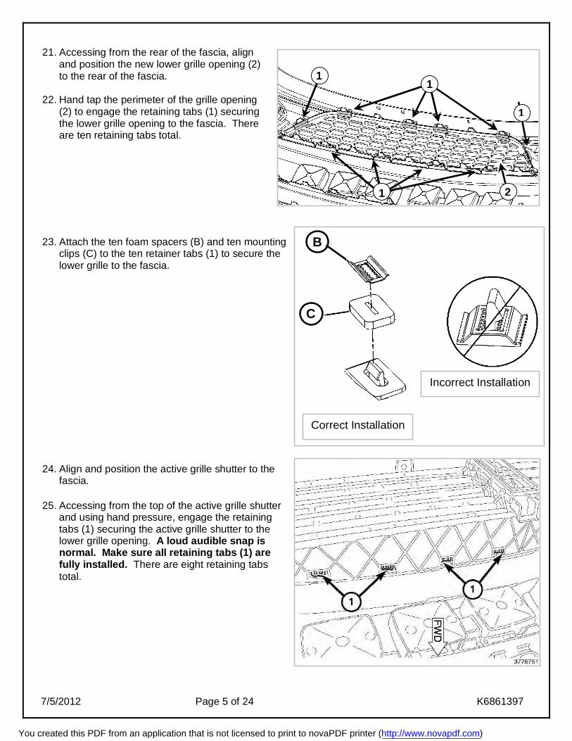
21. Accessing from the rear of the fascia, align
and position the new lower grille opening (2) to the rear of the fascia.
22. Hand tap the perimeter of the grille opening (2) to engage the retaining tabs (1) securing the lower grille opening to the fascia. There are ten retaining tabs total.
23. Attach the ten foam spacers (B) and ten mounting clips (C) to the ten retainer tabs (1) to secure the lower grille to the fascia.
24. Align and position the active grille shutter to the fascia.
25. Accessing from the top of the active grille shutter
and using hand pressure, engage the retaining tabs (1) securing the active grille shutter to the lower grille opening. A loud audible snap is normal. Make sure all retaining tabs (1) are fully installed. There are eight retaining tabs total.
1 1
1
1 2
Incorrect Installation
Correct Installation
B
C
You created this PDF from an application that is not licensed to print to novaPDF printer (http://www.novapdf.com)

7/5/2012 Page 6 of 24 K6861397
26. Accessing from the rear of the fascia, install the
fastener (2) securing the active grille shutter (1) to the fascia. Tighten the fastener securely. Repeat on the opposite side.
27. Accessing from the underside of the fascia, install
the two fasteners (2) securing the active grille shutter (1) to the fascia. Tighten the fasteners securely.
You created this PDF from an application that is not licensed to print to novaPDF printer (http://www.novapdf.com)
7/5/2012 Page 7 of 24 K6861397
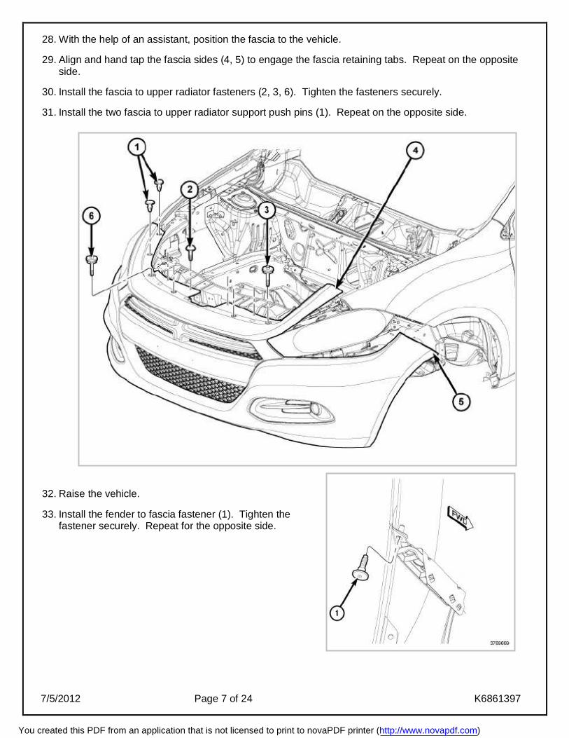
28. With the help of an assistant, position the fascia to the vehicle. 29. Align and hand tap the fascia sides (4, 5) to engage the fascia retaining tabs. Repeat on the opposite
side. 30. Install the fascia to upper radiator fasteners (2, 3, 6). Tighten the fasteners securely. 31. Install the two fascia to upper radiator support push pins (1). Repeat on the opposite side.
32. Raise the vehicle. 33. Install the fender to fascia fastener (1). Tighten the
fastener securely. Repeat for the opposite side.
You created this PDF from an application that is not licensed to print to novaPDF printer (http://www.novapdf.com)

7/5/2012 Page 8 of 24 K6861397
34. If equipped, connect the fog lamps. 35. Accessing from under the vehicle, connect the active grille shutter wire harness. 36. Position the fascia lower closeout panel (1), install the thirteen fasteners (2) securing the fascia lower
close out panel. Tighten the fasteners securely. 37. Install the front splash shield.
38. Lower the vehicle. 39. Connect the negative battery cable.
40. Close the hood.
You created this PDF from an application that is not licensed to print to novaPDF printer (http://www.novapdf.com)
7/5/2012 Page 9 of 24 K6861397
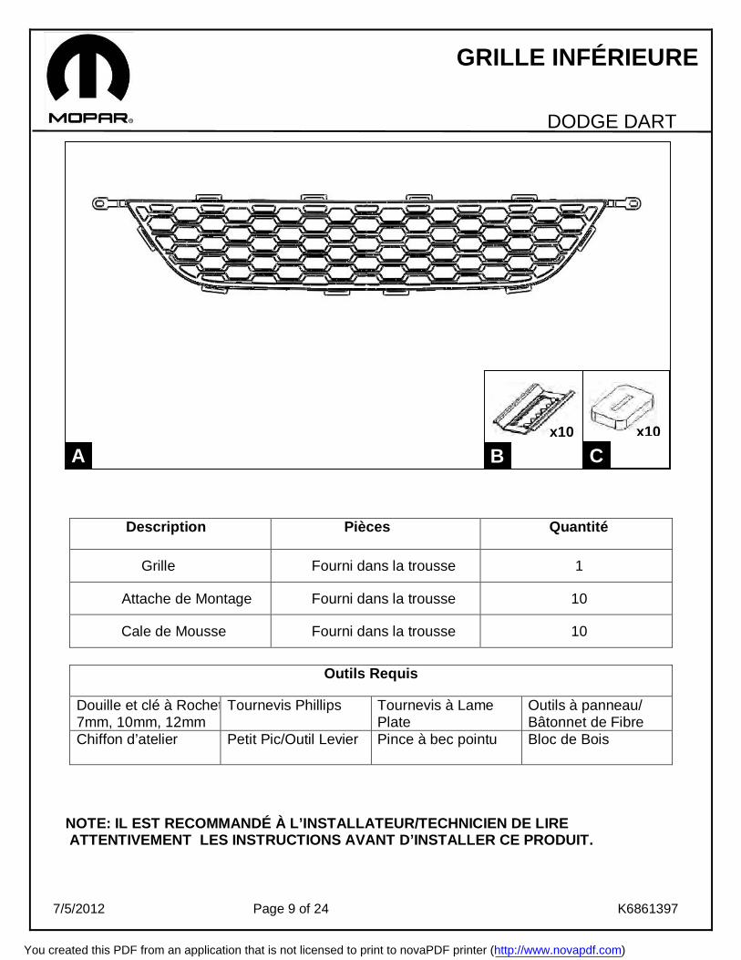
GRILLE INFÉRIEURE
DODGE DART
Description Pièces Quantité
Grille Fourni dans la trousse 1
Attache de Montage Fourni dans la trousse 10
Cale de Mousse Fourni dans la trousse 10
Outils Requis
Douille et clé à Rochet 7mm, 7mm, 10mm, 12mm
Tournevis Phillips Tournevis à Lame Plate
Outils à panneau/ Bâtonnet de Fibre
Chiffon d’atelier Petit Pic/Outil Levier
Pince à bec pointu Bloc de Bois
NOTE: IL EST RECOMMANDÉ À L’INSTALLATEUR/TECHNICIEN DE LIRE ATTENTIVEMENT LES INSTRUCTIONS AVANT D’INSTALLER CE PRODUIT.
A
C
B x10 x10
You created this PDF from an application that is not licensed to print to novaPDF printer (http://www.novapdf.com)
7/5/2012 Page 10 of 24 K6861397
1. Ouvrez le capot
2. Déconnectez le câble négatif de la batterie.
3. Soulevez et supportez le véhicule.
4. Enlevez le bouclier anti éclaboussure avant.
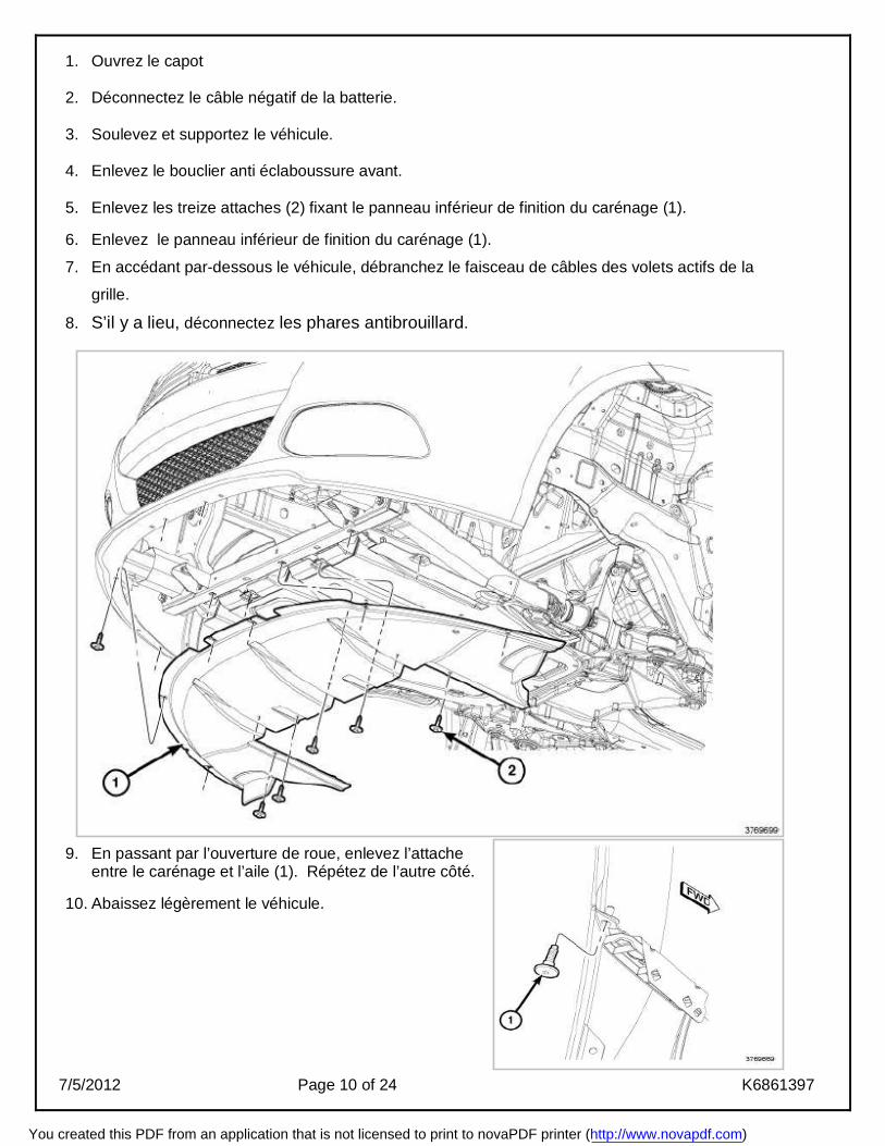
5. Enlevez les treize attaches (2) fixant le panneau inférieur de finition du carénage (1). 6. Enlevez le panneau inférieur de finition du carénage (1).
7. En accédant par-dessous le véhicule, débranchez le faisceau de câbles des volets actifs de la
grille.
8. S’il y a lieu, déconnectez les phares antibrouillard.
9. En passant par l’ouverture de roue, enlevez l’attache entre le carénage et l’aile (1). Répétez de l’autre côté.
10. Abaissez légèrement le véhicule.
You created this PDF from an application that is not licensed to print to novaPDF printer (http://www.novapdf.com)
7/5/2012 Page 11 of 24 K6861397
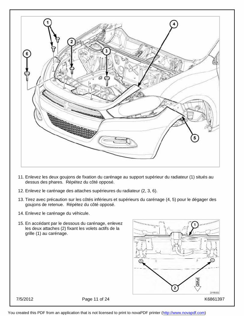
11. Enlevez les deux goujons de fixation du carénage au support supérieur du radiateur (1) situés au dessus des phares. Répétez du côté opposé.
12. Enlevez le carénage des attaches supérieures du radiateur (2, 3, 6).
13. Tirez avec précaution sur les côtés inférieurs et supérieurs du carénage (4, 5) pour le dégager des
goujons de retenue. Répétez du côté opposé.
14. Enlevez le carénage du véhicule.
15. En accédant par le dessous du carénage, enlevez les deux attaches (2) fixant les volets actifs de la grille (1) au carénage.
You created this PDF from an application that is not licensed to print to novaPDF printer (http://www.novapdf.com)

7/5/2012 Page 12 of 24 K6861397
16. En accédant par l’arrière du carénage, enlevez l’attache(2) fixant les volets actifs de la grille (1) au carénage. Répétez du côté opposé.
17. En passant par le dessus des volets actifs de la
grille et en utilisant un petit levier ou l’équivalent, dégagez les languettes de retenus (1) fixant les volets actifs de la grille au bas de l’ouverture de la grille. Il y a huit languettes de retenue au total.
18. Enlevez les volets actifs du carénage. 19. En passant par l’arrière du carénage et en utilisant
un petit levier ou l’équivalent, dégagez les languettes de retenus restantes (1) fixant l’ouverture de la grille inférieure (2) au carénage. Il y a dix-sept languettes de retenue au total.
20. Enlevez l’ouverture de la grille inférieure du
carénage.
You created this PDF from an application that is not licensed to print to novaPDF printer (http://www.novapdf.com)

7/5/2012 Page 13 of 24 K6861397
21. En accédant par l’arrière du carénage, alignez et positionnez la nouvelle ouverture de grille inférieure (2) sur l’arrière du carénage.
22. Tapez légèrement à la main le périmètre de l’ouverture de la grille (2) pour engager les languettes de retenue(1) fixant l’ouverture de la grille inférieure au carénage. Il y a dix languettes de retenue au total.
23. Attachez les dix cales en mousse (B) et les dix attaches de montages(C) aux dix languettes de retenue (1) pour fixer la grille inférieure au carénage.
24. Alignez et positionnez les volets actifs de la
grille sur le carénage. 25. En accédant par le dessus des volets actifs de la
grille, engagez les languettes de retenue (1) fixant ainsi les volets actifs de la grille à l’ouverture de la grille inférieure. Un fort claquement est normal lors de l’installation. Assurez-vous que toutes les languettes de retenue (1) soient pleinement installées. Il y a huit languettes de retenue au total.
1 1
1
1 2
Installation Incorrecte
Installation Correcte
B
C
You created this PDF from an application that is not licensed to print to novaPDF printer (http://www.novapdf.com)
7/5/2012 Page 14 of 24 K6861397
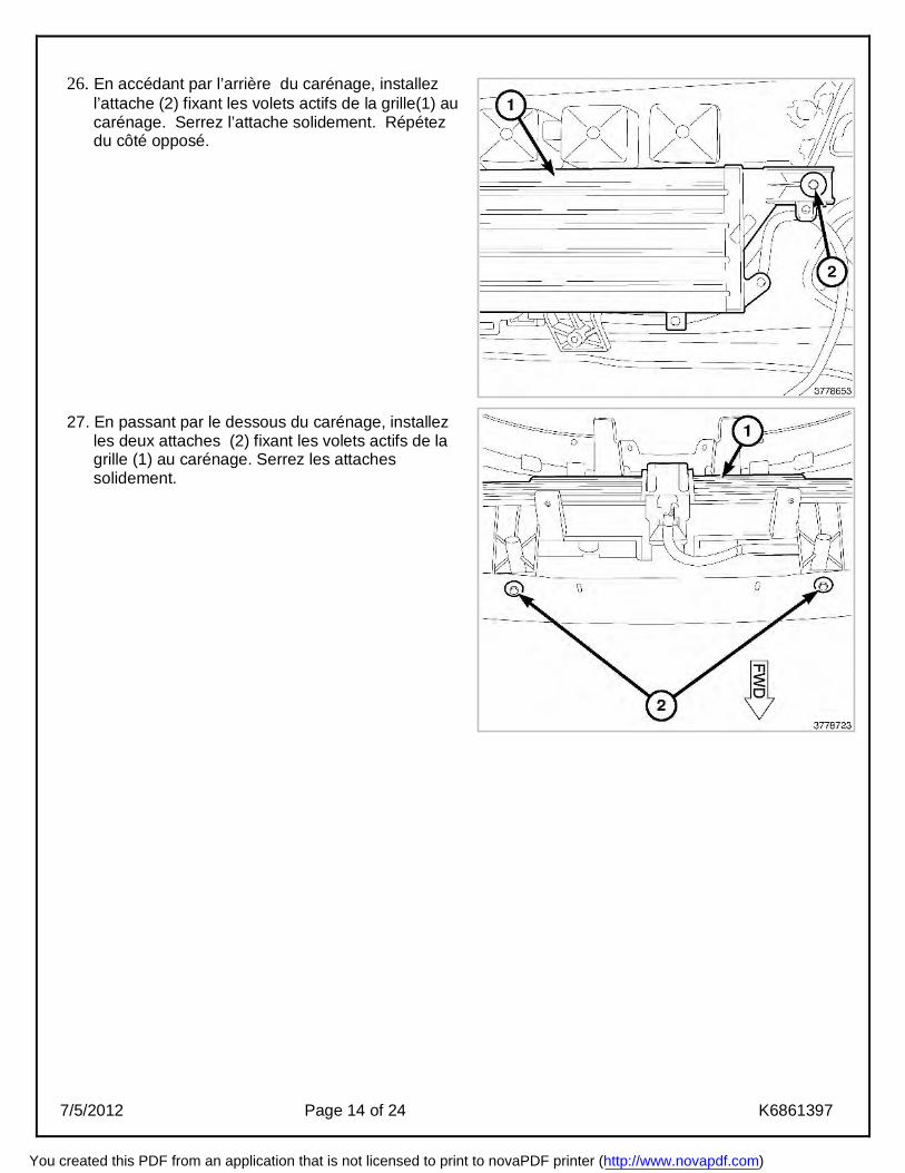
26. En accédant par l’arrière du carénage, installez
l’attache (2) fixant les volets actifs de la grille(1) au carénage. Serrez l’attache solidement. Répétez du côté opposé.
27. En passant par le dessous du carénage, installez
les deux attaches (2) fixant les volets actifs de la grille (1) au carénage. Serrez les attaches solidement.
You created this PDF from an application that is not licensed to print to novaPDF printer (http://www.novapdf.com)

7/5/2012 Page 15 of 24 K6861397
28. Avec l’aide d’un assistant, mettez en position sur le véhicule le carénage avant. 29. Alignez et tapotez à la main les côtés du carénage (4, 5) pour engager les languettes de retenue.
Répétez du côté opposé. 30. Installez le carénage aux attaches du support supérieur de radiateur (2, 3, 6). Serrez les attaches
solidement. 31. Enlevez les deux goujons de fixation du carénage au support supérieur du radiateur (1) situés au
dessus des phares. Répétez du côté opposé.
32. Soulevez le véhicule. 33. Installez l’attache entre l’aile et le carénage (1). Serrez
l’attache solidement. Répétez du côté opposé.
You created this PDF from an application that is not licensed to print to novaPDF printer (http://www.novapdf.com)
7/5/2012 Page 16 of 24 K6861397
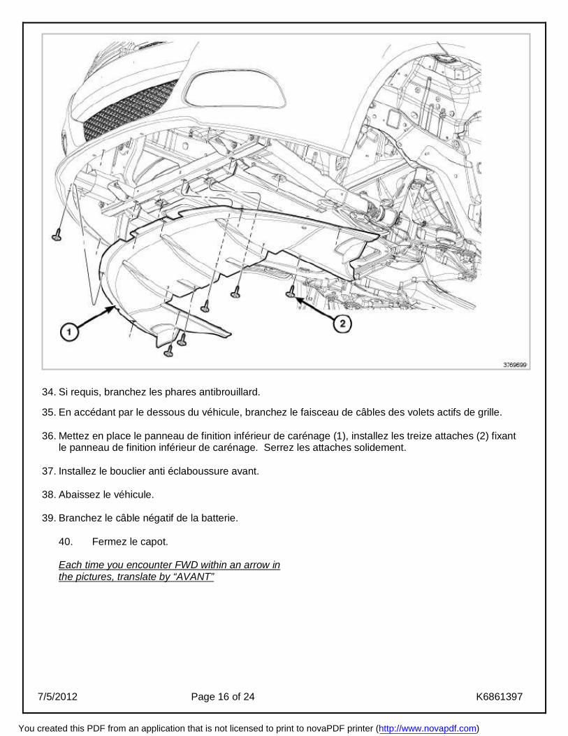
34. Si requis, branchez les phares antibrouillard. 35. En accédant par le dessous du véhicule, branchez le faisceau de câbles des volets actifs de grille. 36. Mettez en place le panneau de finition inférieur de carénage (1), installez les treize attaches (2) fixant
le panneau de finition inférieur de carénage. Serrez les attaches solidement. 37. Installez le bouclier anti éclaboussure avant.
38. Abaissez le véhicule. 39. Branchez le câble négatif de la batterie.
40. Fermez le capot. Each time you encounter FWD within an arrow in the pictures, translate by “AVANT”
You created this PDF from an application that is not licensed to print to novaPDF printer (http://www.novapdf.com)
7/5/2012 Page 17 of 24 K6861397
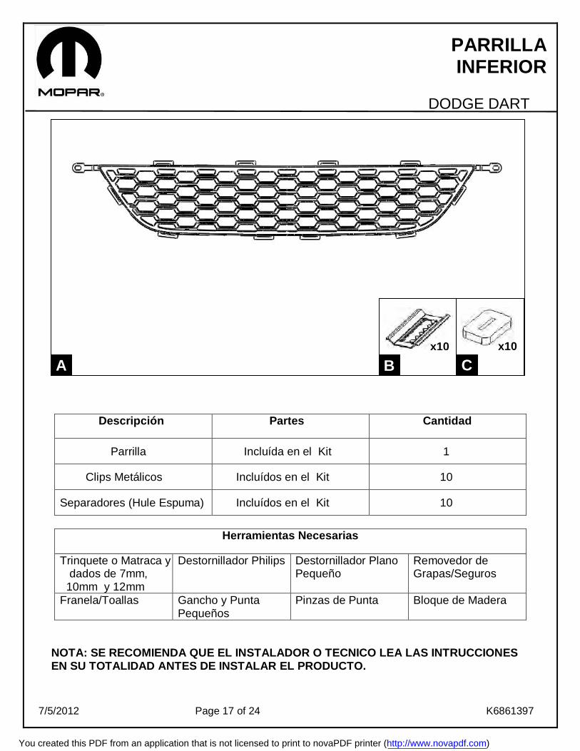
PARRILLA INFERIOR
DODGE DART
Descripción Partes Cantidad
Parrilla Incluída en el Kit 1
Clips Metálicos Incluídos en el Kit 10
Separadores (Hule Espuma) Incluídos en el Kit 10
Herramientas Necesarias
Trinquete o Matraca y dados de 7mm, 10mm y 12mm
Destornillador Philips Destornillador Plano Pequeño
Removedor de Grapas/Seguros
Franela/Toallas Gancho y Punta Pequeños
Pinzas de Punta Bloque de Madera
NOTA: SE RECOMIENDA QUE EL INSTALADOR O TECNICO LEA LAS INTRUCCIONES EN SU TOTALIDAD ANTES DE INSTALAR EL PRODUCTO.
A
C
B x10 x10
You created this PDF from an application that is not licensed to print to novaPDF printer (http://www.novapdf.com)
7/5/2012 Page 18 of 24 K6861397
1. Abra el cofre.
2. Desconecte el cable negativo de la batería.
3. Levante y sostenga el vehículo.
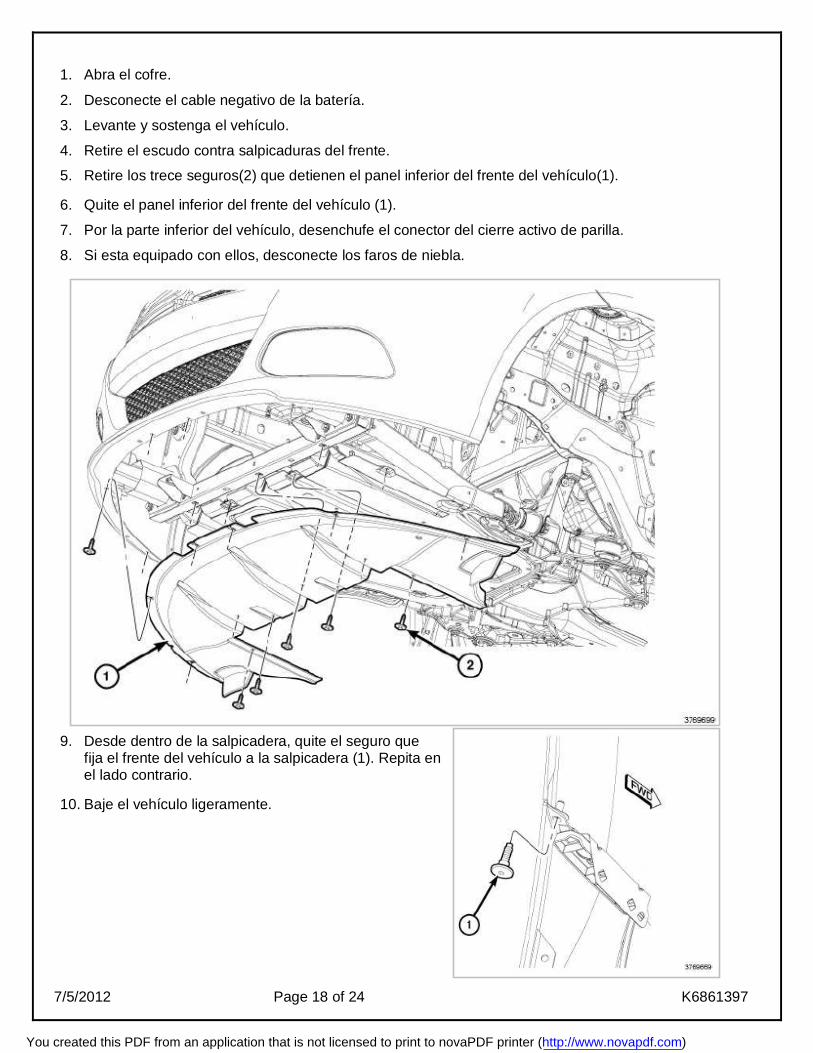
4. Retire el escudo contra salpicaduras del frente.
5. Retire los trece seguros(2) que detienen el panel inferior del frente del vehículo(1).
6. Quite el panel inferior del frente del vehículo (1).
7. Por la parte inferior del vehículo, desenchufe el conector del cierre activo de parilla.
8. Si esta equipado con ellos, desconecte los faros de niebla.
9. Desde dentro de la salpicadera, quite el seguro que fija el frente del vehículo a la salpicadera (1). Repita en el lado contrario.
10. Baje el vehículo ligeramente.
You created this PDF from an application that is not licensed to print to novaPDF printer (http://www.novapdf.com)
7/5/2012 Page 19 of 24 K6861397
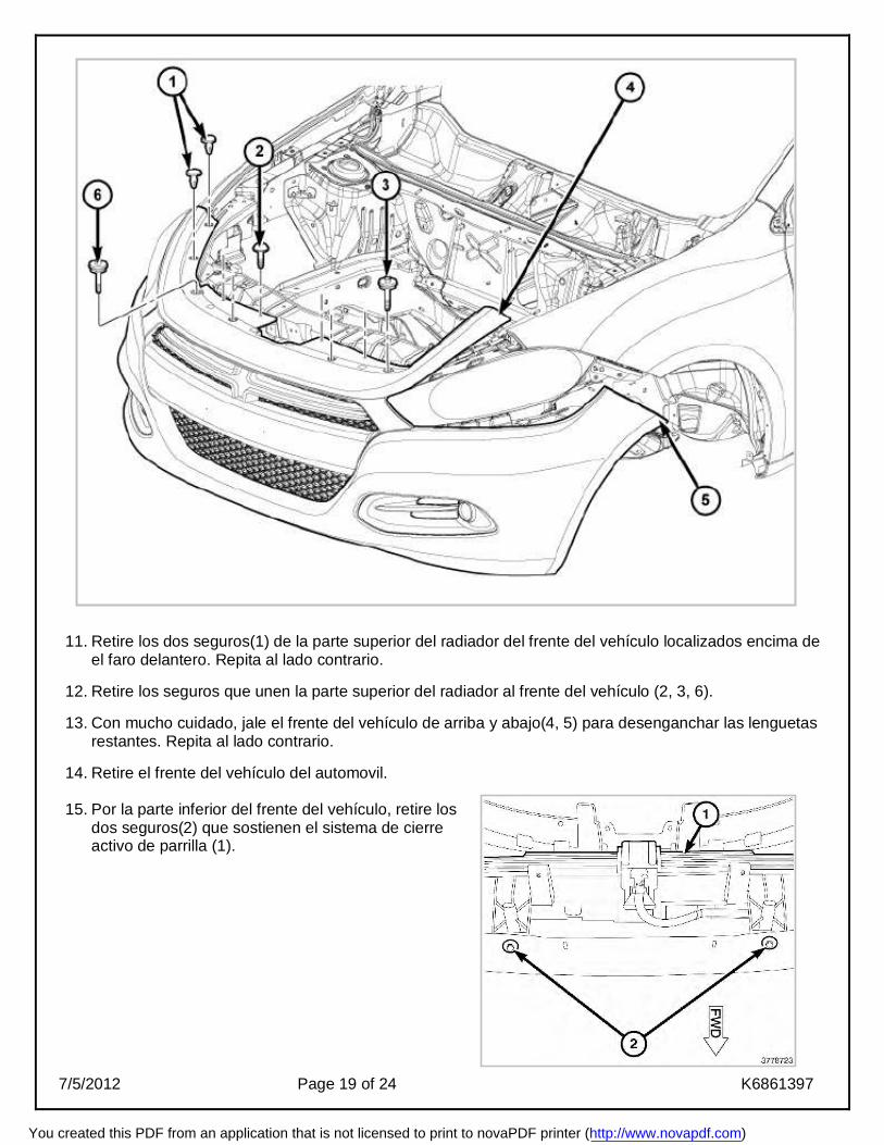
11. Retire los dos seguros(1) de la parte superior del radiador del frente del vehículo localizados encima de el faro delantero. Repita al lado contrario.
12. Retire los seguros que unen la parte superior del radiador al frente del vehículo (2, 3, 6).
13. Con mucho cuidado, jale el frente del vehículo de arriba y abajo(4, 5) para desenganchar las lenguetas restantes. Repita al lado contrario.
14. Retire el frente del vehículo del automovil.
15. Por la parte inferior del frente del vehículo, retire los dos seguros(2) que sostienen el sistema de cierre activo de parrilla (1).
You created this PDF from an application that is not licensed to print to novaPDF printer (http://www.novapdf.com)
7/5/2012 Page 20 of 24 K6861397
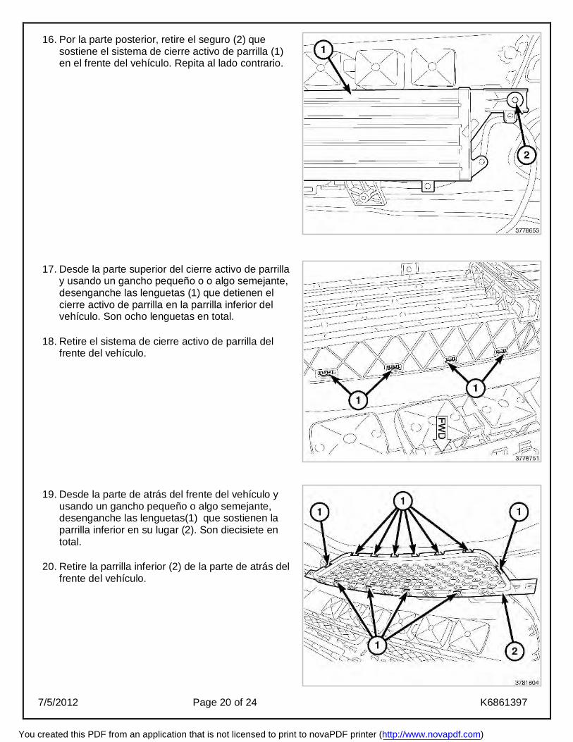
16. Por la parte posterior, retire el seguro (2) que sostiene el sistema de cierre activo de parrilla (1) en el frente del vehículo. Repita al lado contrario.
17. Desde la parte superior del cierre activo de parrilla
y usando un gancho pequeño o o algo semejante, desenganche las lenguetas (1) que detienen el cierre activo de parrilla en la parrilla inferior del vehículo. Son ocho lenguetas en total.
18. Retire el sistema de cierre activo de parrilla del frente del vehículo.
19. Desde la parte de atrás del frente del vehículo y
usando un gancho pequeño o algo semejante, desenganche las lenguetas(1) que sostienen la parrilla inferior en su lugar (2). Son diecisiete en total.
20. Retire la parrilla inferior (2) de la parte de atrás del
frente del vehículo.
You created this PDF from an application that is not licensed to print to novaPDF printer (http://www.novapdf.com)
7/5/2012 Page 21 of 24 K6861397
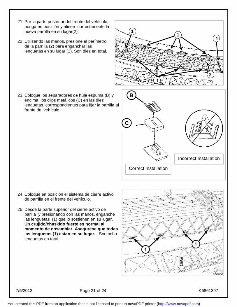
21. Por la parte posterior del frente del vehículo,
ponga en posición y alinee correctamente la nueva parrilla en su lugar(2).
22. Utilizando las manos, presione el perímetro de la parrilla (2) para enganchar las lenguetas en su lugar (1). Son diez en total.
23. Coloque los separadores de hule espuma (B) y encima los clips metálicos (C) en las diez lenguetas correspondientes para fijar la parrilla al frente del vehículo.
24. Coloque en posición el sistema de cierre activo de parrilla en el frente del vehículo.
25. Desde la parte superior del cierre activo de
parilla y presionando con las manos, enganche las lenguetas (1) que lo sostienen en su lugar. Un crujido/chaskido fuerte es normal al momento de ensamblar. Asegurese que todas las lenguetas (1) estan en su lugar. Son ocho lenguetas en total.
1 1
1
1 2
Incorrect Installation
Correct Installation
B
C
You created this PDF from an application that is not licensed to print to novaPDF printer (http://www.novapdf.com)
7/5/2012 Page 22 of 24 K6861397
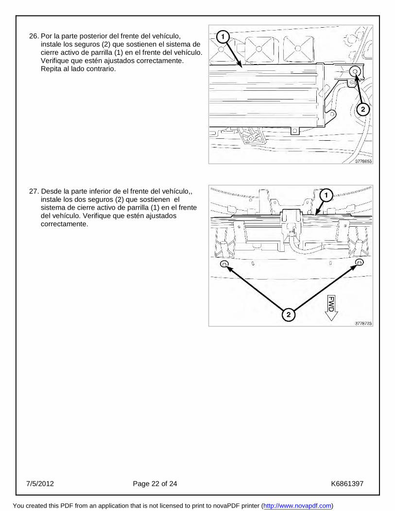
26. Por la parte posterior del frente del vehículo,
instale los seguros (2) que sostienen el sistema de cierre activo de parrilla (1) en el frente del vehículo. Verifique que estén ajustados correctamente. Repita al lado contrario.
27. Desde la parte inferior de el frente del vehículo,,
instale los dos seguros (2) que sostienen el sistema de cierre activo de parrilla (1) en el frente del vehículo. Verifique que estén ajustados correctamente.
You created this PDF from an application that is not licensed to print to novaPDF printer (http://www.novapdf.com)

7/5/2012 Page 23 of 24 K6861397
28. Con ayuda de un asistente, coloque el frente del vehículo de nuevo en el automóvil. 29. Alinee y presione los lados superior e inferior del frente del vehículo (4, 5), de modo que enganchen
las lenguetas en su lugar correspondiente. Repita al lado contrario. 30. Instale los seguros de la parte superior del radiador (2, 3, 6). Verifique que estén ajustados
correctamente. 31. Instale los seguros de la parte superior de el radiador(1) que van encima
de los faros delanteros. Repita al lado contrario.
32. Levante el vehículo de nuevo. 33. Instale el seguro que une el frente del vehículo con la
salpicadera (1). Verifique que esté ajsutado correctamente. Repita al lado contrario.
You created this PDF from an application that is not licensed to print to novaPDF printer (http://www.novapdf.com)

7/5/2012 Page 24 of 24 K6861397
34. Si estan instalados, conecte los faros para niebla. 35. Desde abajo del vehículo, conecte el enchufe del cierre activo de parrilla.
36. Coloque el panel inferior del frente del vehículo en su lugar(1), instalando los trece seguros (2) y
verificando que estén ajustados correctamente. 37. Instale el escudo contra salpicaduras del frente.
38. Baje el vehículo. 39. Conecte el cable negativo a la batería.
40. Cierre el cofre.
You created this PDF from an application that is not licensed to print to novaPDF printer (http://www.novapdf.com)