Embed Size (px)
Citation preview

LOW VOLTAGE MOTORSInstallation, operation, maintenance and safety manual
PRODUCT MANUAL
MOTEURS À BASSE TENSIONL’installation, le fonctionnement, la maintenance et le manuel de sécurité
TechtopCanada.com
FRANÇAIS
ENGLISH
FRANÇAISENGLISH
1 | Techtop Motors TechtopCanada.com
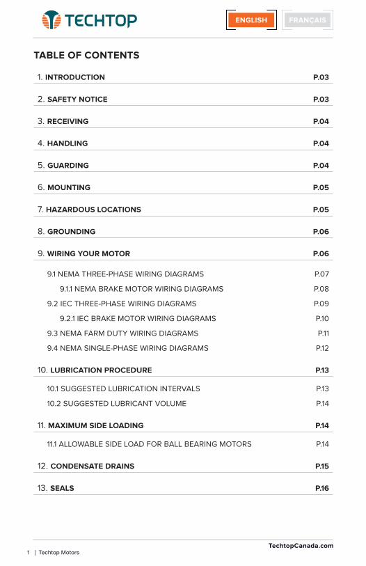
1. INTRODUCTION P.03
2. SAFETY NOTICE P.03
3. RECEIVING P.04
4. HANDLING P.04
5. GUARDING P.04
6. MOUNTING P.05
7. HAZARDOUS LOCATIONS P.05
8. GROUNDING P.06
9. WIRING YOUR MOTOR P.06
9.1 NEMA THREE-PHASE WIRING DIAGRAMS P.07
9.1.1 NEMA BRAKE MOTOR WIRING DIAGRAMS P.08
9.2 IEC THREE-PHASE WIRING DIAGRAMS P.09
9.2.1 IEC BRAKE MOTOR WIRING DIAGRAMS P.10
9.3 NEMA FARM DUTY WIRING DIAGRAMS P.11
9.4 NEMA SINGLE-PHASE WIRING DIAGRAMS P.12
10. LUBRICATION PROCEDURE P.13
10.1 SUGGESTED LUBRICATION INTERVALS P.13
10.2 SUGGESTED LUBRICANT VOLUME P.14
11. MAXIMUM SIDE LOADING P.14
11.1 ALLOWABLE SIDE LOAD FOR BALL BEARING MOTORS P.14
12. CONDENSATE DRAINS P.15
13. SEALS P.16
TABLE OF CONTENTS

Techtop Motors | 2 TechtopCanada.com
TABLE DES MATIÈRES
1. INTRODUCTION P.17
2. AVIS DE SÉCURITÉ P.17
3. RÉCEPTION P.18
4. MANIPULATION P.18
5. PROTECTION P.18
6. MONTAGE P.19
7. ZONES DANGEREUSES P.19
8. MISE À LA TERRE P.20
9. BRANCHEMENT DU MOTEUR P.20
9.1 SCHEMA DE BRANCHEMENT TRIPHASE NEMA P.21
9.1.1 SCHEMAS DE BRANCHEMENT MOTEUR FREIN NEMA P.22
9.2 SCHEMA DE BRANCHEMENT TRIPHASE METRIQUE P.23
9.2.1 SCHEMAS DE BRANCHEMENT MOTEUR FREIN METRIQUE P.24
9.3 SCHEMA DE BRANCHEMENT MOTEURS USAGE DE FERME P.25
9.4 SCHEMA DE BRANCHEMENT SIMPLE PHASE NEMA P.26
10. PROCÉDURE DE LUBRIFICATION P.27
10.1 INTERVALLE DE LUBRIFICATION SUGGÉRÉE P.27
10.2 LUBRIFICATION SUGGÉRÉE AU VOLUME P.28
11. CHARGE LATÉRALE MAXIMALE P.28
11.1 CHARGE LATÉRALE ADMISSIBLE POUR MOTEUR AVEC ROULEMENT À BILLES
P.28
12. DRAIN DE CONDENSATION P.29
13. REMPLACEMENT DU JOINT D’ÉTANCHÉITÉ P.30
FRANÇAISENGLISH
FRANÇAISENGLISH
3 | Techtop Motors TechtopCanada.com
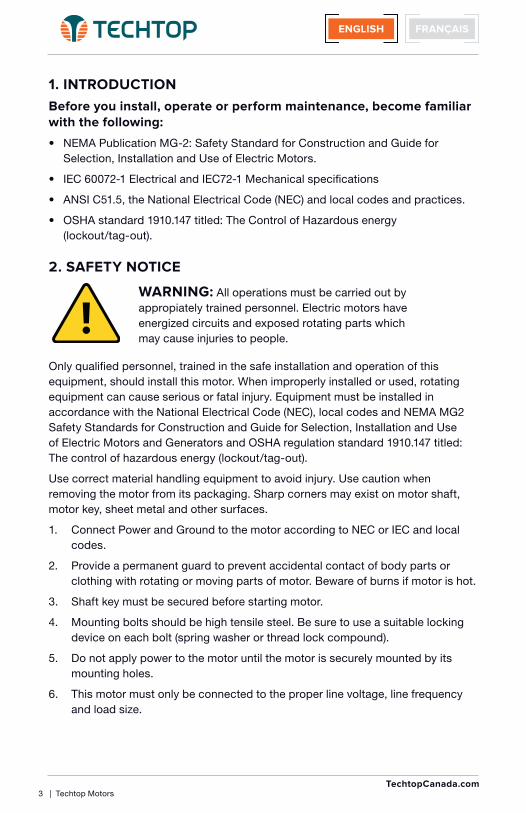
1. INTRODUCTION
Before you install, operate or perform maintenance, become familiar with the following:
• NEMA Publication MG-2: Safety Standard for Construction and Guide for Selection, Installation and Use of Electric Motors.
• IEC 60072-1 Electrical and IEC72-1 Mechanical specifications
• ANSI C51.5, the National Electrical Code (NEC) and local codes and practices.
• OSHA standard 1910.147 titled: The Control of Hazardous energy (lockout/tag-out).
2. SAFETY NOTICE
WARNING: All operations must be carried out by appropiately trained personnel. Electric motors have energized circuits and exposed rotating parts which may cause injuries to people.
Only qualified personnel, trained in the safe installation and operation of this equipment, should install this motor. When improperly installed or used, rotating equipment can cause serious or fatal injury. Equipment must be installed in accordance with the National Electrical Code (NEC), local codes and NEMA MG2 Safety Standards for Construction and Guide for Selection, Installation and Use of Electric Motors and Generators and OSHA regulation standard 1910.147 titled: The control of hazardous energy (lockout/tag-out).
Use correct material handling equipment to avoid injury. Use caution when removing the motor from its packaging. Sharp corners may exist on motor shaft, motor key, sheet metal and other surfaces.
1. Connect Power and Ground to the motor according to NEC or IEC and local codes.
2. Provide a permanent guard to prevent accidental contact of body parts or clothing with rotating or moving parts of motor. Beware of burns if motor is hot.
3. Shaft key must be secured before starting motor.
4. Mounting bolts should be high tensile steel. Be sure to use a suitable locking device on each bolt (spring washer or thread lock compound).
5. Do not apply power to the motor until the motor is securely mounted by its mounting holes.
6. This motor must only be connected to the proper line voltage, line frequency and load size.

FRANÇAISENGLISH
Techtop Motors | 4 TechtopCanada.com
7. Motors are not to be used for load holding or restraining unless a properly sized brake is installed. If a motor mounted brake is installed, provide proper safeguards in case of brake failure.
8. Disconnect all power services, stop the motor and allow it to cool before servicing.
9. For single phase motors, discharge the start and/or run capacitors before servicing.
10. Do not by-pass or render any inoperative safety devices.
3. RECEIVING
Once you receive your motor, instantly observe the condition of the shipping container. Immediately report any damage to the commercial carrier that delivered your motor.
Verify that the part number of the motor you received is the same as the part number listed on your purchase order.
4. HANDLING
Use correct material handling equipment to avoid injury. Use caution when removing the motor from its packaging. Sharp corners may exist on motor shaft, motor key, sheet metal and other surfaces.
5. GUARDING
After motor installation is complete, a guard of suitable dimensions must be constructed and installed around the motor. This guard must prevent personnel from coming in contact with any moving parts of the motor or drive assembly, but must allow sufficient cooling air to pass over the motor. If a motor mounted brake is installed, provide proper safeguards for personnel in case of brake failure.
All parts should be permanently guarded to prevent accidental contact by personnel. Accidental contact with body parts or clothing can cause serious or fatal injury. When this motor is installed according to these instructions, it complies with the EEC Machinery Directive. Electromagnetic Compatibility (EMC) requirements for CE compliance are met when the incoming power is purely sinusoidal.
WARNING: Guards must be installed to form a safe and uncompromised perimeter around rotating parts such as couplings, pulleys, external fans, and unused shaft extensions.

FRANÇAISENGLISH
5 | Techtop Motors TechtopCanada.com
6. MOUNTING
FOOT MOUNTED: Foot mounted motors should be mounted to a rigid foundation to prevent excessive vibration. Shims may be used if the location is uneven. Improper alignment may void the motor’s warranty.
FLANGE MOUNTED: Flange mounted motors should be properly seated and aligned. Note: If improper rotation direction is detrimental to the load, check the rotation or ‘bump’ the motor prior to coupling the load to the motor shaft.
V-BELT DRIVE: Mount the sheave pulley close to the motor housing. Allow clearance for end to end movement of the motor shaft. Do not over tighten belts as this may cause premature bearing failure or shaft breakage.
DIRECT COUPLED: Direct coupled motors should be carefully aligned and the shaft should rotate freely without binding or drag.
Note: Techtop Motors with frame 254T and larger are shipped with an opposite drive end bearing lock. If front end bearing locks are desired, please contact Techtop for assistance.
7. HAZARDOUS LOCATIONS
CLASS I (Gases, Vapors)
Group A: Acetylene
Group B: Butadiene, ethylene oxide, hydrogen, propylene oxide
Group C: Acetaldehyde, cyclopropane, diethel ether, ethylene, isoprene
Group D: Acetone, acrylonitrite, ammonia, benzene, butane, ethylene dichloride, gasoline, hexane, methane, methanol, naphtha, propane, propylene, styrene, toluene, vinyl acetate, vinyl chloride, xylem
CLASS II (Combustible Dusts)
Group E: Aluminum, magnesium and other metal dusts with similar characteristics.
Group F: Carbon black, coke or coal dust
Group G: Flour, starch or grain dust
Division 1: In which ignitable concentrations of hazards exists, under normal operating conditions and/or where hazard is caused by frequent maintenance or repair work or frequent equipment failure.
Division 2: In which ignitable concentrations of hazards are handled, processed or used, but are normally in closed containers or closed systems from which they can only escape through accidental rupture or breakdown of such containers.

FRANÇAISENGLISH
Techtop Motors | 6 TechtopCanada.com
8. GROUNDING
Ground the motor according to NEC and local codes. In the USA, consult the National Electrical Code, Article 430 for information on grounding of motors and generators, and Article 250 for general information on grounding. In making the ground connection, the installer should make certain that there is a solid and permanent metallic connection between the ground point, the motor or generator terminal housing, and the motor or generator frame. In non-USA locations consult the appropriate national or local code applicable.
9. WIRING YOUR MOTOR
Connect the motor as shown in the connection diagram on the motor nameplate. Be sure to identify the proper wiring diagram for the motor you are installing. If you have difficulty determining the proper wiring diagram for your motor, please contact Techtop for assistance. If this motor is installed as part of a motor control drive system, connect and protect the motor according to the control manufacturer’s diagram. When using AC motors with frequency inverters, be certain that the motors maximum speed rating is not exceeded. The wiring, fusing and grounding must comply with the National Electrical Code or IEC and local codes. Note: If improper rotation direction is detrimental to the load, check the rotation or ‘bump’ the motor prior to coupling the load to the motor shaft. When the motor is coupled to the load and started, it should start quickly and run smoothly. If not, stop the motor immediately and determine the cause. Possible causes are: low voltage at the motor, motor connections are not correct or the load is too heavy. Check the motor current after a few minutes of operation and compare the measured current with the nameplate rating.
WARNING: Do not touch electrical connections unless you first ensure that power has been disconnected. Please refer to: OSHA standard 1910.147 titled: The Control of Hazardous energy (lockout/tag-out).

FRANÇAISENGLISH
7 | Techtop Motors TechtopCanada.com
Direct-on-line (DOL) full voltage starting208-230/460V 60Hz
575V 60Hz
Does Not Apply
Wye-Delta starting (Wye Start/Delta Run)
Does Not Apply
Direct-on-line (DOL) full voltage starting Wye-Delta starting (Wye Start/Delta Run)
T1
T7
T2
T8
T3
T9
T4 T5 T6
L1 L2 L3LOW VOLTAGE
T1
T7
T2
T8
T3
T9
L1 L2 L3HIGH VOLTAGE
T4 T5 T6
NEMA 215T Frame & Smaller9 Leads YY/Y
HIGH VOLTAGE
T1
T12
T2
T10
T3
T11
L1 L2 L3LOW VOLTAGE
T7 T8 T9
T6 T4 T5
T1
T12
T2
T10
T3
T11
L1 L2 L3
T7 T8 T9
T4 T5 T6
NEMA 254T Frame & Larger12 Leads ΔΔ/Δ
T1
T6
T2
T4
T3
T5
L1 L2 L3
NEMA > 100HP6 Leads Δ(460V)
SINGLE VOLTAGE (460V)
T1
T6
T2
T4
T3
T5
L1 L2 L3
NEMA 254T Frame & Larger6 Leads Δ
NEMA 215T Frame & Smaller3 Leads Y
L1 L2 L3
T1 T2 T3
T1
T12
T2
T10
T3
T11
L1 L2 L3LOW VOLTAGE DELTA RUN
T7 T8 T9
T6 T4 T5
T1
T12
T2
T10
T3
T11
L1 L2 L3
T7 T8 T9
T4 T5 T6
HIGH VOLTAGE DELTA RUN
T1
T7
T2
T8
T3
T9
L1 L2 L3LOW VOLTAGE WYE START
T10 T11 T12
T1
T4
T2
T5
T3
T6
L1 L2 L3
T7 T8 T9
HIGH VOLTAGE WYE START
T4 T5 T6
T10 T11 T12
T1
T6
T2
T4
T3
T5
L1 L2 L3SINGLE VOLTAGE WYE START
T1
T6
T2
T4
T3
T5
L1 L2 L3SINGLE VOLTAGE DELTA RUN
T1
T6
T2
T4
T3
T5
L1 L2 L3WYE START
T1
T6
T2
T4
T3
T5
L1 L2 L3DELTA RUN
Lead ColorT1, T4 BlueT2, T5 WhiteT3, T6 Orange
Lead ColorT1 BlueT2 WhiteT3 Orange
Lead ColorT1, T4 BlueT2, T5 WhiteT3, T6 Orange
Lead ColorT1, T4 BlueT2, T5 WhiteT3, T6 Orange
T7, T10 YellowT8, T11 BlackT9, T12 Red
Lead ColorT1, T4 BlueT2, T5 WhiteT3, T6 Orange
T7 YellowT8 BlackT9 Red
9.1 NEMA THREE-PHASE WIRING DIAGRAMS
1. CCW rotation facing ODE for connections shown
2. Swap any two input lines to reverse rotation

FRANÇAISENGLISH
Techtop Motors | 8 TechtopCanada.com
Direct-on-line (DOL) full voltage starting208-230/460V 60Hz
575V 60Hz
Does Not Apply
Wye-Delta starting (Wye Start/Delta Run)
Does Not Apply
Direct-on-line (DOL) full voltage starting Wye-Delta starting (Wye Start/Delta Run)
NEMA215T Frame & Smaller9 Leads YY/Y
NEMA 215T Frame & Smaller3 Leads Y
Lead ColorT1 BlueT2 WhiteT3 Orange
Lead ColorT1, T4 BlueT2, T5 WhiteT3, T6 Orange
T7 YellowT8 BlackT9 Red
L1 L2 L3
T1 T2 T3
~ _ + ~
BRIDGE RECTIFIER
DC BRAKE
T1 T2 T3
T4 T5 T6
L1 L2 L3LOW VOLTAGE
T1
T7
T2
T8
T3
T9
L1 L2 L3HIGH VOLTAGE
T4 T5 T6
~ _ + ~
BRIDGE RECTIFIER
DC BRAKE
T7 T8 T9
~ _ + ~
BRIDGE RECTIFIER
DC BRAKE
Bridge Rectifier located inside motor terminal box
Bridge Rectifier located inside motor terminal box
9.1.1 NEMA BRAKE MOTOR WIRING DIAGRAMS
1. CCW rotation facing ODE for connections shown
2. Swap any two input lines to reverse rotation
WARNING: Surface temperatures of motor enclosures may reach temperatures which can cause discomfort or injury to personnel coming in contact with hot surfaces. Protection should be provided by the user to protect against accidental contact with hot surfaces. Failure to observe this precaution could result in bodily injury.

FRANÇAISENGLISH
9 | Techtop Motors TechtopCanada.com
9.2 IEC THREE-PHASE WIRING DIAGRAMS
Direct-on-line (DOL) full voltage starting208-230/460V 60Hz
575V 60Hz
Does Not Apply
Wye-Delta starting (Wye Start/Delta Run)
Does Not Apply
Direct-on-line (DOL) full voltage starting Wye-Delta starting (Wye Start/Delta Run)
LOW VOLTAGE DELTA RUN
HIGH VOLTAGE
U1
U3
V1
V3
W1
W3
U2 V2 W2
L1 L2 L3LOW VOLTAGE
U1
U3
V1
V3
W1
W3
L1 L2 L3HIGH VOLTAGE
U2 V2 W2
IEC132M Frame & Smaller9 Leads YY/Y
U1
U3
V1
V3
W1
W3
L1 L2 L3LOW VOLTAGE
W2 U2 V2
W4 U4 V4
U1
W4
V1
U4
W1
V4
L1 L2 L3
U2 V2 W2
U3 V3 W3
IEC 160M Frame & Larger12 Leads ΔΔ/Δ
U1
W2
V1
U2
W1
V2
L1 L2 L3
IEC > 100HP6 Leads Δ(460V)
SINGLE VOLTAGE (460V)
IEC 160M Frame & Larger6 Leads Δ
IEC 132M Frame & Smaller6 Leads Y
HIGH VOLTAGE DELTA RUN
U1
U3
V1
V3
W1
W3
L1 L2 L3LOW VOLTAGE WYE START
U4 V4 W4
U1
U2
V1
V2
W1
W2
L1 L2 L3
U3 V3 W3
HIGH VOLTAGE WYE START
U2 V2 W2
W4 U4 V4
U1
W2
V1
U2
W1
V2
L1 L2 L3SINGLE VOLTAGE WYE START
U1
W2
V1
U2
W1
V2
L1 L2 L3SINGLE VOLTAGE DELTA RUN
WYE START DELTA RUN
U1
W2
V1
U2
W1
V2
L1 L2 L3
U1
W2
V1
U2
W1
V2
L1 L2 L3
U1
W2
V1
U2
W1
V2
L1 L2 L3
U1
W2
V1
U2
W1
V2
L1 L2 L3
U1
U3
V1
V3
W1
W3
L1 L2 L3
W2 U2 V2
W4 U4 V4
U1
W4
V1
U4
W1
V4
L1 L2 L3
U2 V2 W2
U3 V3 W3
1. CCW rotation facing ODE for connections shown
2. Swap any two input lines to reverse rotation

FRANÇAISENGLISH
Techtop Motors | 10 TechtopCanada.com
1. CCW rotation facing ODE for connections shown
2. Swap any two input lines to reverse rotation
9.2.1 IEC BRAKE MOTOR WIRING DIAGRAMS
Direct-on-line (DOL) full voltage starting208-230/460V 60Hz
575V 60Hz
Does Not Apply
Wye-Delta starting (Wye Start/Delta Run)
Does Not Apply
Direct-on-line (DOL) full voltage starting Wye-Delta starting (Wye Start/Delta Run)
IEC132M Frame & Smaller9 Leads YY/Y
IEC 132M Frame & Smaller6 Leads Y
L1 L2 L3
~ _ + ~BRIDGE RECTIFIER
DC BRAKE
U1 V1 W1
U2 V2 W2
L1 L2 L3LOW VOLTAGE
U1
U3
V1
V3
W1
W3
L1 L2 L3HIGH VOLTAGE
U2 V2 W2
~ _ + ~BRIDGE RECTIFIER
DC BRAKE
U3 V3 W3
~ _ + ~BRIDGE RECTIFIER
DC BRAKE
Bridge Rectifier located inside motor terminal box
Bridge Rectifier located inside motor terminal box
W2 U2 V2
U1 V1 W1
WARNING: Surface temperatures of motor enclosures may reach temperatures which can cause discomfort or injury to personnel coming in contact with hot surfaces. Protection should be provided by the user to protect against accidental contact with hot surfaces. Failure to observe this precaution could result in bodily injury.

FRANÇAISENGLISH
11 | Techtop Motors TechtopCanada.com
132
P1
P2
T 1
M
M
S
T2
T3
T4
T8
T5
132
P1
P2M
S
T5
T4
T8
T 1
P1
T2
T4
T5
P2
T8
T3
L1 L2LOW VOLTAGE
NEMA Farm Duty56 Frame 1/3-2HP Manual Reset Thermal O/L Protection
P1 T4
T5
L1 L2
NEMA Farm Duty182T-213T Frame3-7.5HPManual Reset Thermal O/L Protection
T1 T8
P1 T4
T5
L1 L2
NEMA Farm Duty215T Frame10HPManual Reset Thermal O/L Protection
P2 T8
132
P1
M
S
T5
T 1
T4
T8
T1
Lead ColorP1 BlueP2 BrownT2T3T4 YellowT5 BlackT8 Red
OrangeWhite
P1
T2
T8
T3
T4
T5
L1 L2
HIGH VOLTAGE
P2
Thermally Protected Single-Phase Circuit Diagram
Direct-on-line (DOL) full voltage starting115/208-230V 60Hz Thermally Protected Single-Phase Circuit Diagram
Direct-on-line (DOL) full voltage starting208-230V 60Hz
9.3 NEMA FARM DUTY WIRING DIAGRAMS
1. CCW rotation facing ODE for connections shown
2. Interchange T5 and T8 to reverse rotation

FRANÇAISENGLISH
Techtop Motors | 12 TechtopCanada.com
9.4 NEMA SINGLE-PHASE WIRING DIAGRAMS
132
P1
P2
T 1
M
M
S
T2
T3
T4
T8
T5
P1
T2
T4
T5
P2
T8
T3
L1 L2LOW VOLTAGE
HIGH VOLTAGE
NEMA Single-Phase56 Frame 1/3-2HP Manual Reset Thermal O/L Protection
Lead ColorP1 BlueP2 BrownT2T3T4 YellowT5 BlackT8 Red
OrangeWhite
2 Pole Only
P1
T2
T8
T3
T4
T5
L1 L2P2
Direct-on-line (DOL) full voltage starting115/208-230V 60Hz Thermally Protected Single-Phase Circuit Diagram
T1
M
M
S
T2
T3
T4
T8
T5
T1 T5
T4
L1 L2
NEMA Single-Phase56 Frame1/3-2HP
T8T2
T3
LOW VOLTAGE
HIGH VOLTAGE
T1 T5
T4
L1 L2
T8 T2
T3
Lead ColorT1 BlueT2 WhiteT3 OrangeT4 YellowT5 BlackT8 Red
Direct-on-line (DOL) full voltage starting115/208-230V 60Hz Single-Phase Circuit Diagram
4 Pole Only
1. CCW rotation facing ODE for connections shown
2. Interchange T5 and T8 to reverse rotation
WARNING: Surface temperatures of motor enclosures may reach temperatures which can cause discomfort or injury to personnel coming in contact with hot surfaces. Protection should be provided by the user to protect against accidental contact with hot surfaces. Failure to observe this precaution could result in bodily injury.

FRANÇAISENGLISH
13 | Techtop Motors TechtopCanada.com
1. Re-lubrication is recommended when the motor is warm and the shaft is stationary.
2. Remove all dirt and wipe the outside of the grease fills and drains.
3. Clean the grease fitting (or area around grease hole, if equipped with slotted grease screws). If the motor has a purge plug, remove it. Motors can be re-greased while stopped (at less than 80°C) or while running.
4. When applicable, locate the grease inlet at the top of the bearing hub. If the motor is not equipped with grease fitting, clean the area and replace the 1/8-inch pipe plug with grease fitting.
5. Remove grease drain plug located opposite the grease inlet.
6. Apply grease gun to fitting (or grease hole). Too much grease or injecting grease too quickly can cause premature bearing failure. Slowly apply the recommended amount of grease, taking a few minutes or so to apply.
7. Operate the motor for 20 minutes and reinstall the purge plug if previously removed.
8. Install grease drain plug located opposite the grease inlet.
10.1 SUGGESTED LUBRICATION INTERVALS
FrameRPM (r/min) Duty Interval
NEMA IEC
254T-365T 160M-225M 1800 or less standard 2 years
254T-365T 160M-225M 1800 or less severe 1 year
254T-365T 160M-225M > 1800 standard 6 months
254T-365T 160M-225M > 1800 severe 3 months
404T-500 250M-315L 1800 or less standard 1 year
404T-500 250M-315L 1800 or less severe 6 months
404T-500 250M-315L > 1800 standard 3 months
404T-500 250M-315L > 1800 severe 1 month
10. LUBRICATION PROCEDURE
CAUTION: Keep grease clean. Mixing dissimilar grease is not recommended and may result in premature bearing failure.

FRANÇAISENGLISH
Techtop Motors | 14 TechtopCanada.com
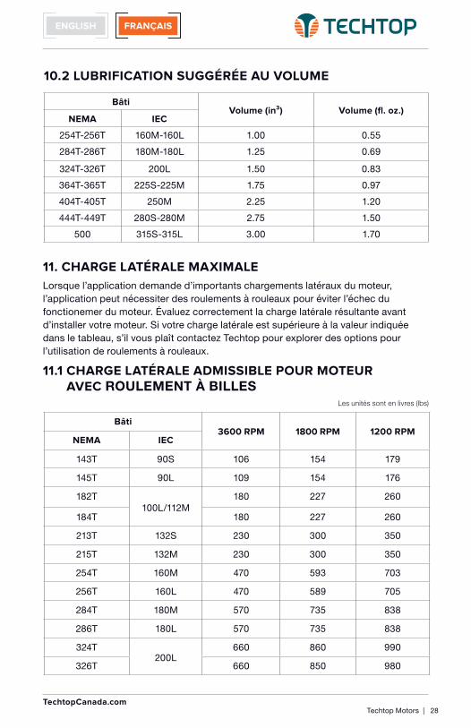
11. MAXIMUM SIDE LOADING
When application calls for significant side loading of the motor, the application may require roller bearings to avoid early life failure of motor.
Properly assess the resultant side load before installing your motor. If your side load exceeds the value shown in the table, please contact Techtop to explore options for use of roller bearings.
11.1 ALLOWABLE SIDE LOAD FOR BALL BEARING MOTORS
FrameVolume (in³) Volume (fl. oz.)
NEMA IEC
254T-256T 160M-160L 1.00 0.55
284T-286T 180M-180L 1.25 0.69
324T-326T 200L 1.50 0.83
364T-365T 225S-225M 1.75 0.97
404T-405T 250M 2.25 1.20
444T-449T 280S-280M 2.75 1.50
500 315S-315L 3.00 1.70
10.2 SUGGESTED LUBRICANT VOLUME
Frame3600 RPM 1800 RPM 1200 RPM
NEMA IEC
143T 90S 106 154 179
145T 90L 109 154 176
182T100L/112M
180 227 260
184T 180 227 260
213T 132S 230 300 350
215T 132M 230 300 350
254T 160M 470 593 703
256T 160L 470 589 705
284T 180M 570 735 838
286T 180L 570 735 838
324T200L
660 860 990
326T 660 850 980
Units are in pounds (lbs)

FRANÇAISENGLISH
15 | Techtop Motors TechtopCanada.com
Frame3600 RPM 1800 RPM 1200 RPM
NEMA IEC
364T 225S 820 1080 1240
365T 225M 820 1080 1240
404T250M
-- 1270 1450
405T -- 1290 1480
444T 280S -- 1560 1760
445T 280M -- 1520 1760
447T--
-- 1450 1660
449T -- 1490 1660
500 315S/M/L -- 1490 1660
11.1 CONTINUED
If the application calls for significant thrust loads, please contact Techtop to determine if you have the correct motor for your application.
Notes:
1. Overhung loads are considered to include belt tension and sheave weight.
2. Belt loads considered to act in a vertically downward direction.
3. To determine load at shaft end subtract 15%.
4. Overhung load radial limits are based on a bearing L-10 life of 26,280 hours.
5. Overhung load limits don’t include effects of any unbalanced magnetic pull.
12. CONDENSATE DRAINS
Many Techtop motors come standard with one way sintered brass breather drains. These drains allow the motor to expel liquids from the casing without allowing liquid to enter the motor. Drains may require periodic maintenance to keep them clean of debris and flowing freely. Occasionally, remove the brass drains and wash them thoroughly. Eliminate any built up debris which may be impeding their operation.
For motors which are equipped with rubber plugs in their condensate drain holes, be sure to remove the plug (i.e. especially if the motor is installed in a location where condensate build up is likely).
In all instances, ensure that the drain is in the lowest portion of the motor. Some motors may require rotation of the end plates (i.e. if the mounting location is not a typical horizontal mounting).
For IEC frame, select the lower value of the equivalent NEMA frames.
Units are in pounds (lbs)

FRANÇAISENGLISH
Techtop Motors | 16 TechtopCanada.com
13. SEALS
Inspect seals regularly for excessive wear which could lead to bearing failure. If significant wear is present, please contact Techtop for replacement seals.
If you have any questions, not answered in this manual, please contact Techtop at 1.888.286.1820 or e-mail us at [email protected].
FRANÇAISENGLISH
17 | Techtop Motors TechtopCanada.com
Seul le personnel qualifié, formé à la sécurité de l’installation et le fonctionnement de cet équipement, devrait installer ce moteur. S’il est mal installé ou utilisé, l’équipement rotatif peut causer des blessures graves ou mortelles. L’équipement doit être installé conformément au Code national d’électricité (NEC), les codes locaux et NEMA Normes de sécurité pour la construction et MG2 Guide pour la sélection, l’installation et l’utilisation de moteurs électriques et générateurs ainsi que la réglementation OSHA 1910.147 norme intitulée: Le contrôle des énergies dangereuses (verrouillage / tag-out).
Utiliser un équipement de manutention de matériel correctement pour éviter les blessures. Faites preuve de prudence lorsque vous retirez le moteur de son emballage. Des angles coupants peuvent exister sur l’arbre moteur, clé du moteur, de la tôle et d’autres surfaces.
1. Faire la connexion des fils d’alimentation et de mise à la terre selon le NEC ou IEC et les codes locaux.
2. Installer un garde permanent pour éviter tout contact accidentel avec des parties du corps ou des vêtements avec des pièces en rotation ou des moteurs en mouvement. Méfiez-vous des brûlures si le moteur est chaud.
3. La clé de l’arbre doit être fixée et sécurisee avant de démarrer le moteur.
4. Les boulons de fixation doivent être en acier à haute résistance. Veillez à utiliser un dispositif de verrouillage approprié sur chaque boulon (rondelle ou une colle à fillet de verrouillage).
5. N’appliquez pas d’alimentation au moteur jusqu’à ce qu’il soit bien installé, en toute sécurité par ses trous de montage.
6. Les moteurs doivent être connectés à la tension d’alimentation appropriée, de la fréquence de ligne et de la taille de la charge.
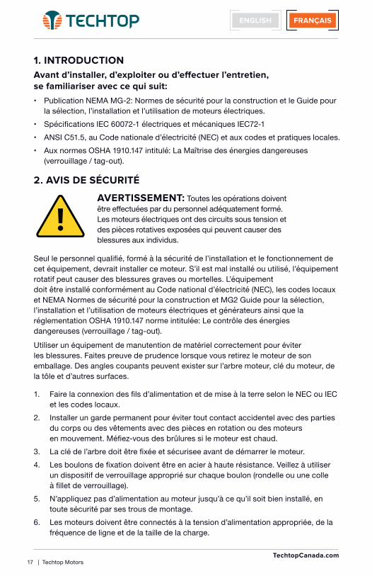
1. INTRODUCTION
Avant d’installer, d’exploiter ou d’effectuer l’entretien, se familiariser avec ce qui suit:
• Publication NEMA MG-2: Normes de sécurité pour la construction et le Guide pour la sélection, l’installation et l’utilisation de moteurs électriques.
• Spécifications IEC 60072-1 électriques et mécaniques IEC72-1 • ANSI C51.5, au Code nationale d’électricité (NEC) et aux codes et pratiques locales. • Aux normes OSHA 1910.147 intitulé: La Maîtrise des énergies dangereuses
(verrouillage / tag-out).
2. AVIS DE SÉCURITÉ
AVERTISSEMENT: Toutes les opérations doivent être effectuées par du personnel adéquatement formé. Les moteurs électriques ont des circuits sous tension et des pièces rotatives exposées qui peuvent causer des blessures aux individus.

FRANÇAISENGLISH
Techtop Motors | 18 TechtopCanada.com
7. Les moteurs ne doivent pas être utilisés pour le maintien de la charge ou de la restreindre, à moins qu’un frein de taille appropriée soit installée. Si un moteur avec frein est installé, fournir des protection adéquates en cas de défaillance des freins.
8. Débranchez tous les services d’alimentation, arrêtez le moteur et laissez refroidir avant l’entretien.
9. Pour les moteurs monophasés, déchargez les condensateurs de démarage et/ou de marche.
10. Ne pas contourner les dispositifs de sécurité.
3. RÉCEPTION
Une fois que vous recevez votre moteur, observez instantanément l’état de l’emballage d’expédition. Signalez immédiatement tout dommage au transporteur commercial qui a livré votre moteur.
Vérifiez que le numéro de pièce du moteur que vous avez reçu est le même que le numéro de pièce indiqué sur votre bon de commande.
4. MANIPULATION
Utiliser un équipement de manutention de matériel adéquat pour éviter les blessures. Faites preuve de prudence lorsque vous retirez le moteur de son emballage. Les angles coupants peuvent exister sur l’arbre moteur, clé du moteur, de la tôle et d’autres surfaces.
5. PROTECTION
Après que l’installation du moteur soit terminée, un garde protecteur de dimensions appropriées doit être construit, et installé autour du moteur. Cette protection doit empêcher le personnel d’entrer en contact avec n’importe quelle piéce mobile du moteur, mais doit permettre à l’air de refroidissement de passer au-dessus du moteur. Si un moteur avec frein monté est installé, fournir des protections adéquates pour le personnel en cas de défaillance des freins.
AVERTISSEMENT: Les protecteurs doivent être installés pour former un périmètre de sécurité et sans compromettre des parties tels que les accouplements, les poulies, ventilateurs externes et les extensions de l’arbre tournant inutilisés.
Toutes les pièces doivent être isolées en permanence pour empêcher tout contact accidentel par le personnel. Le contact accidentel avec des parties du corps ou des vêtements peut causer des blessures graves ou mortelles. Lorsque ce moteur est installé conformément aux instructions, il est conforme à la Directive Machines CEE. Compatibilité électromagnétique (CEM) pour la conformité CE sont remplies lorsque la puissance d’entrée est purement sinusoïdale.

FRANÇAISENGLISH
19 | Techtop Motors TechtopCanada.com
6. MONTAGE
MONTAGE SUR PATTES: Les moteurs à pattes doivent être installés à une fondation rigide pour éviter des vibrations excessives. Des cales peuvent être utilisées si l’emplacement est inégale. Un mauvais alignement peut annuler la garantie du moteur.
MONTAGE AVEC BRIDE: Les moteurs à bride doivent être correctement installés et alignés. Remarque: si le sens de rotation incorrect est préjudiciable à la charge, vérifier la rotation ou “bump” du moteur avant le couplage de la charge à l’arbre du moteur.
APPLICATION À COURROIE V: Monter la poulie pres du bâti du moteur. Laisser un espace adéquat pour le va-et-vient lateraux de l’arbre du moteur. Ne pas trop serrer la courroie car cela pourrait entraîner une défaillance prématurée des roulements ou rupture de l’arbre.
APPLICATION DIRECT: Moteurs à application direct doivent être soigneusement alignés et l’arbre doit tourner librement sans se lier ni frotter.
Remarque: Les moteurs Techtop avec bâti 254T et plus sont livrés avec un verrou en face de roulement à la fin de l’entraînement. Si les serrures de roulement frontaux sont souhaitées, s’il vous plaît contacter Techtop pour de l’aide.
7. ZONES DANGEREUSES
CLASSE I (gaz, vapeurs)
Groupe A: Acétylène
Groupe B: Butadiène, de l’oxyde d’éthylène, l’hydrogène, l’oxyde de propylène
Groupe C: Acétaldéhyde, du cyclopropane, de l’éther diethel, l’éthylène, l’isoprène
Groupe D: Acétone, acrylonitrite, de l’ammoniac, le benzène, le butane, le dichlorure d’éthylène, de l’essence, de l’hexane, le méthane, le méthanol, le naphta, le propane, le propylène, le styrène, le toluène, l’acétate de vinyle, le chlorure de vinyle, le xylème
CLASSE II (combustibles poussières)
Groupe E: Aluminium, magnésium et autres poussières métalliques ayant des caractéristiques similaires.
Groupe F: Le noir de carbone, le coke ou de poussière de charbon
Groupe G: Farine, l’amidon ou grain de poussière
Division 1: Dans lequels des concentrations inflammables à risque existent, dans des conditions normales de fonctionnement et / ou où le danger est causée par un entretien fréquent ou des travaux de réparation ou de défaillance de l’équipement fréquent.

FRANÇAISENGLISH
Techtop Motors | 20 TechtopCanada.com
Division 2: Dans lesquels les concentrations inflammables de danger sont traitées, ou utilisées, mais sont normalement dans des contenants ou systèmes fermés dont ils ne peuvent pas s’échapper par la rupture accidentelle ou de panne de ces conteneurs.
8. MISE À LA TERRE
Relier le moteur selon l’NEC et les codes locaux. Aux États-Unis, consultez le National Electrical Code, l’article 430 pour des informations sur la mise à la terre des moteurs et des générateurs, et de l’article 250 pour des informations générales sur la mise à la terre. En faisant la mise à la terre, l’installateur doit faire sorte qu’il y ait une connexion métallique solide et permanente entre le point de masse, le moteur ou le boîtier de terminal, et le bâti du moteur ou générateur. Dans les endroits non-USA consulter le code national ou local approprié applicable.
9. BRANCHEMENT DU MOTEUR
Raccorder le moteur comme indiqué dans le schéma de raccordement sur la plaque signalétique du moteur. Assurez-vous d’identifier le schéma de câblage approprié pour le moteur que vous installez. Si vous avez des difficultés à déterminer le schéma de câblage approprié pour votre moteur, s’il vous plaît contactez Techtop pour de l’aide. Si ce moteur est installé en tant que partie d’un système de commande d’entraînement de moteur, brancher et protéger le moteur selon le schéma de la commande du fabricant. Lors de l’utilisation de moteurs à courant alternatif avec des variateurs de fréquence, être certain que la côte de vitesse des moteurs maximale ne soit pas dépassée. Le câblage, fixation et mise à la terre doivent être conformes au Code national de l’électricité ou de la IEC et les codes locaux. Remarque: si le sens de rotation est incorrect et préjudiciable à la charge, vérifier la rotation ou “bump” du moteur avant le couplage de la charge à l’arbre du moteur. Lorsque le moteur est couplé à la charge et démarre, Il devrait partir rapidement et fonctionner en douceur. Sinon, arrêter immédiatement le moteur et déterminer la cause. Les causes possibles sont: basse tension au niveau du moteur, les connexions du moteur ne sont pas correctes ou si la charge est trop lourde. Vérifiez le courant du moteur après quelques minutes de fonctionnement et de comparer le courant mesuré à la plaque signalétique.
AVERTISSEMENT: Ne touchez pas les connexions électriques à moins que vous vérifiez d’abord que l’alim- entation a été déconnectée. S’il vous plaît se référer à: OSHA 1910.147 norme intitulée: La Maîtrise des énergies dangereuses (verrouillage/tag-out).

FRANÇAISENGLISH
21 | Techtop Motors TechtopCanada.com
575V 60Hz
T1
T7
T2
T8
T3
T9
T4 T5 T6
L1 L2 L3
T1
T7
T2
T8
T3
T9
L1 L2 L3
T4 T5 T6
T1
T12
T2
T10
T3
T11
L1 L2 L3
T7 T8 T9
T6 T4 T5
T1
T12
T2
T10
T3
T11
L1 L2 L3
T7 T8 T9
T4 T5 T6
T1
T6
T2
T4
T3
T5
L1 L2 L3
T1
T6
T2
T4
T3
T5
L1 L2 L3
L1 L2 L3
T1 T2 T3
T1
T12
T2
T10
T3
T11
L1 L2 L3
T7 T8 T9
T6 T4 T5
T1
T12
T2
T10
T3
T11
L1 L2 L3
T7 T8 T9
T4 T5 T6
T1
T7
T2
T8
T3
T9
L1 L2 L3
T10 T11 T12
T1
T4
T2
T5
T3
T6
L1 L2 L3
T7 T8 T9
T4 T5 T6
T10 T11 T12
T1
T6
T2
T4
T3
T5
L1 L2 L3
T1
T6
T2
T4
T3
T5
L1 L2 L3
T1
T6
T2
T4
T3
T5
L1 L2 L3
T1
T6
T2
T4
T3
T5
L1 L2 L3
Branchement Direct Voltage 208-230/460V 60Hz
Ne s'applique pas
Star Démarrage / Delta Marche
BASSE TENSION
HAUTE TENSION
NEMA 215T Bâti et plus petits9 Leads YY/Y
Lead CouleurT1, T4 BleuT2, T5 BlancT3, T6 Orange
T7 JauneT8 NoirT9 Rouge
Branchement Direct Voltage Star Démarrage / Delta Marche
Ne s'applique pas
HAUTE TENSION
BASSE TENSION
NEMA 254T Bâti et plus grand12 Leads ΔΔ/Δ
NEMA > 100HP6 Leads Δ(460V)
MONOTENSION (460V)
NEMA 254T Bâti et plus grand6 Leads Δ
NEMA 215T Bâti et plus petits3 Leads Y
BASSE TENSION DELTA MARCHE
HAUTE TENSION DELTA MARCHE
BASSE TENSION STAR DÉMARRAGE
HAUTE TENSION STAR DÉMARRAGE
MONOTENSION STAR DÉMARRAGE MONOTENSION DELTA MARCHE
STAR DÉMARRAGE DELTA MARCHE
Lead CouleurT1, T4 BleuT2, T5 BlancT3, T6 Orange
Lead CouleurT1 BleuT2 BlancT3 Orange
Lead CouleurT1, T4 BleuT2, T5 BlancT3, T6 Orange
T7, T10 JauneT8, T11 NoirT9, T12 Rouge
Lead CouleurT1, T4 BleuT2, T5 BlancT3, T6 Orange
9.1 SCHEMA DE BRANCHEMENT TRIPHASE NEMA
1. Sens de rotation inverse lorsque vue par l’arriere pour le branchement indiqué
2. Interchanger 2 fils de branchement à l’entrée pour changer la rotation

FRANÇAISENGLISH
Techtop Motors | 22 TechtopCanada.com
9.1.1 SCHEMAS DE BRANCHEMENT MOTEUR FREIN NEMA
208-230/460V 60Hz
575V 60Hz
L1 L2 L3
T1 T2 T3
~ _ + ~
BRIDGE RECTIFIER
DC BRAKE
T1 T2 T3
T4 T5 T6
L1 L2 L3
T1
T7
T2
T8
T3
T9
L1 L2 L3
T4 T5 T6
~ _ + ~
BRIDGE RECTIFIER
DC BRAKE
T7 T8 T9
~ _ + ~
BRIDGE RECTIFIER
DC BRAKE
Pont Redresseur situé à l'intérieur de la boîte à bornes du moteur
Pont Redresseur situé à l'intérieur de la boîte à bornes du moteur
Branchement Direct Voltage
Ne s'applique pas
Star Démarrage / Delta Marche
BASSE TENSION
HAUTE TENSION
Branchement Direct Voltage Star Démarrage / Delta Marche
Ne s'applique pas
NEMA 215T Bâti et plus petits9 Leads YY/Y
Lead CouleurT1, T4 BleuT2, T5 BlancT3, T6 Orange
T7 JauneT8 NoirT9 Rouge
NEMA 215T Bâti et plus petits3 Leads Y
Lead CouleurT1 BleuT2 BlancT3 Orange
1. Sens de rotation inverse lorsque vue par l’arriere pour le branchement indiqué
2. Interchanger 2 fils de branchement à l’entrée pour changer la rotation
AVERTISSEMENT: Les températures de surface du bâti du moteur peuvent atteindre des températures qui peuvent causer de l’inconfort ou des blessures pour le personnel en contact avec les surfaces chaudes. La protection devrait être fournie par l’utilisateur pour se protéger contre tout contact accidentel avec les surfaces chaudes. Le non-respect de cette précaution peut entraîner des blessures corporelles.

FRANÇAISENGLISH
23 | Techtop Motors TechtopCanada.com
208-230/460V 60Hz
575V 60Hz
U1
U3
V1
V3
W1
W3
U2 V2 W2
L1 L2 L3
U1
U3
V1
V3
W1
W3
L1 L2 L3
U2 V2 W2
U1
U3
V1
V3
W1
W3
L1 L2 L3
W2 U2 V2
W4 U4 V4
U1
W4
V1
U4
W1
V4
L1 L2 L3
U2 V2 W2
U3 V3 W3
U1
W2
V1
U2
W1
V2
L1 L2 L3
U1
U3
V1
V3
W1
W3
L1 L2 L3
U4 V4 W4
U1
U2
V1
V2
W1
W2
L1 L2 L3
U3 V3 W3
U2 V2 W2
W4 U4 V4
U1
W2
V1
U2
W1
V2
L1 L2 L3
U1
W2
V1
U2
W1
V2
L1 L2 L3
U1
W2
V1
U2
W1
V2
L1 L2 L3
U1
W2
V1
U2
W1
V2
L1 L2 L3
U1
W2
V1
U2
W1
V2
L1 L2 L3
U1
W2
V1
U2
W1
V2
L1 L2 L3
U1
U3
V1
V3
W1
W3
L1 L2 L3
W2 U2 V2
W4 U4 V4
U1
W4
V1
U4
W1
V4
L1 L2 L3
U2 V2 W2
U3 V3 W3
Branchement Direct Voltage Star Démarrage / Delta Marche
Branchement Direct Voltage
Ne s'applique pas
Star Démarrage / Delta Marche
Ne s'applique pas
BASSE TENSION
HAUTE TENSION
IEC 132M Bâti et plus petits9 Leads YY/Y
HAUTE TENSION
BASSE TENSIONIEC 160M Bâti et plus grand12 Leads ΔΔ/Δ
IEC > 100HP6 Leads Δ(460V)
MONOTENSION (460V)
IEC 160M Bâti et plus grand6 Leads Δ
IEC 132M Bâti et plus petits6 Leads Y
BASSE TENSION DELTA MARCHE
HAUTE TENSION DELTA MARCHE
BASSE TENSION STAR DÉMARRAGE
HAUTE TENSION STAR DÉMARRAGE
MONOTENSION STAR DÉMARRAGE MONOTENSION DELTA MARCHE
STAR DÉMARRAGE DELTA MARCHE
9.2 SCHEMA DE BRANCHEMENT TRIPHASE METRIQUE
1. Sens de rotation inverse lorsque vue par l’arriere pour le branchement indiqué
2. Interchanger 2 fils de branchement à l’entrée pour changer la rotation

FRANÇAISENGLISH
Techtop Motors | 24 TechtopCanada.com
9.2.1 SCHEMAS DE BRANCHEMENT MOTEUR FREIN METRIQUE
208-230/460V 60Hz
575V 60Hz Branchement Direct Voltage Star Démarrage / Delta Marche
Branchement Direct Voltage
Ne s'applique pas
Star Démarrage / Delta Marche
Ne s'applique pas
BASSE TENSION
HAUTE TENSION
IEC 132M Bâti et plus petits9 Leads YY/Y
IEC 132M Bâti et plus petits6 Leads Y
L1 L2 L3
~ _ + ~BRIDGE RECTIFIER
DC BRAKE
U1 V1 W1
U2 V2 W2
L1 L2 L3
U1
U3
V1
V3
W1
W3
L1 L2 L3
U2 V2 W2
~ _ + ~BRIDGE RECTIFIER
DC BRAKE
U3 V3 W3
~ _ + ~BRIDGE RECTIFIER
DC BRAKE
Pont Redresseur situé à l'intérieur de la boîte à bornes du moteur
Pont Redresseur situé à l'intérieur de la boîte à bornes du moteur
W2 U2 V2
U1 V1 W1
1. Sens de rotation inverse lorsque vue par l’arriere pour le branchement indiqué
2. Interchanger 2 fils de branchement à l’entrée pour changer la rotation
AVERTISSEMENT: Les températures de surface du bâti du moteur peuvent atteindre des températures qui peuvent causer de l’inconfort ou des blessures pour le personnel en contact avec les surfaces chaudes. La protection devrait être fournie par l’utilisateur pour se protéger contre tout contact accidentel avec les surfaces chaudes. Le non-respect de cette précaution peut entraîner des blessures corporelles.

FRANÇAISENGLISH
25 | Techtop Motors TechtopCanada.com
132
P1
P2
T 1
M
M
S
T2
T3
T4
T8
T5
132
P1
P2M
S
T5
T4
T8
T 1
P1
T2
T4
T5
P2
T8
T3
L1 L2
P1 T4
T5
L1 L2
T1 T8
P1 T4
T5
L1 L2
P2 T8
132
P1
M
S
T5
T 1
T4
T8
T1
P1
T2
T8
T3
T4
T5
L1 L2P2
115/208-230V 60Hz
208-230V 60Hz
NEMA Ferme Moteurs215T Bâti10HPProtection thermique de surcharge avec réinitialisation manuel
BASSE TENSION
HAUTE TENSION
NEMA Ferme Moteurs56 Bâti 1/3-2HP Protection thermique de surcharge avec réinitialisation manuel
NEMA Ferme Moteurs182T-213T Bâti3-7.5HPProtection thermique de surcharge avec réinitialisation manuel
Lead CouleurP1 BleuP2 MarronT2T3T4 JauneT5 NoirT8 Rouge
OrangeBlanc
Branchement Direct Voltage
Branchement Direct Voltage Diagramme De Branchement Moteur Simple Phase Avec Protection Thermique
Diagramme De Branchement Moteur Simple Phase Avec Protection Thermique
9.3 SCHEMA DE BRANCHEMENT MOTEURS USAGE DE FERME
1. Sens de rotation inverse lorsque vue par l’arriere pour le branchement indiqué
2. Interchanger 2 fils de branchement à l’entrée pour changer la rotation

FRANÇAISENGLISH
Techtop Motors | 26 TechtopCanada.com
9.4 SCHEMA DE BRANCHEMENT SIMPLE PHASE NEMA
132
P1
P2
T 1
M
M
S
T2
T3
T4
T8
T5
P1
T2
T4
T5
P2
T8
T3
L1 L2
P1
T2
T8
T3
T4
T5
L1 L2P2
115/208-230V 60Hz
T1
M
M
S
T2
T3
T4
T8
T5
T1 T5
T4
L1 L2
T8T2
T3
T1 T5
T4
L1 L2
T8 T2
T3
115/208-230V 60Hz
NEMA Simple Phase56 Bâti1/3-2HP
Lead CouleurT1 BleuT2 BlancT3 OrangeT4 JuaneT5 NoirT8 Rouge
BASSE TENSION
HAUTE TENSION
NEMA Ferme Moteurs56 Bâti 1/3-2HP Protection thermique de surcharge avec réinitialisation manuel
Lead CouleurP1 BleuP2 MarronT2T3T4 JauneT5 NoirT8 Rouge
OrangeBlanc
Branchement Direct Voltage
Branchement Direct Voltage
Diagramme De Branchement Moteur Simple Phase Avec Protection Thermique
BASSE TENSION
HAUTE TENSION
Diagramme De Branchement Moteur Simple Phase
2 Pôles
4 Pôles
AVERTISSEMENT: Les températures de surface du bâti du moteur peuvent atteindre des températures qui peuvent causer de l’inconfort ou des blessures pour le personnel en contact avec les surfaces chaudes. La protection devrait être fournie par l’utilisateur pour se protéger contre tout contact accidentel avec les surfaces chaudes. Le non-respect de cette précaution peut entraîner des blessures corporelles.
1. Sens de rotation inverse lorsque vue par l’arriere pour le branchement indiqué
2. Interchanger 2 fils de branchement à l’entrée pour changer la rotation

FRANÇAISENGLISH
27 | Techtop Motors TechtopCanada.com
1. La re-lubrification est recommandée lorsque le moteur est chaud et l’arbre est à l’arrêt.
2. Enlevez toute la saleté et essuyez l’extérieur des conduits de graisse et des drains.
3. Nettoyez le graisseur (ou la zone autour du trou de la graisse, si équipé de vis de graisse à fente). Si le moteur a un bouchon de purge, retirez-le. Les moteurs peuvent être re-graissés à l’arrêt (à moins de 80°C) ou lors de l’exécution.
4. Le cas échéant, localisez l’entrée de la graisse dans la partie supérieure du moyeu de palier. Si le moteur n’est pas équipé de graisseur, nettoyez la zone et remplacez le bouchon de tuyau de 1/8 pouces avec graisseur.
5. Retirez le bouchon de vidange de la graisse situé en face de l’entrée de la graisse.
6. Appliquez de la graisse à pistolet au raccord (ou trou de la graisse). Trop de graisse ou injecter de la graisse trop rapidement peut entraîner une défaillance prématurée des roulements. Appliquez progressivement la quantité de graisse recommandée, en prenant quelques minutes pour l’appliquer.
7. Faire fonctionner le moteur pendant 20 minutes et remettre le bouchon de purge si précédemment retirée.
8. Installez le bouchon de vidange de la graisse située en face de l’entrée de la graisse.
10.1 INTERVALLE DE LUBRIFICATION SUGGÉRÉE
BâtiVitesse Fonction Intervalle
NEMA IEC
254T-365T 160M-225M 1800 ou moins standard 2 ans
254T-365T 160M-225M 1800 ou moins severe 1 an
254T-365T 160M-225M > 1800 standard 6 mois
254T-365T 160M-225M > 1800 severe 3 mois
404T-500 250M-315L 1800 ou moins standard 1 an
404T-500 250M-315L 1800 ou moins severe 6 mois
404T-500 250M-315L > 1800 standard 3 mois
404T-500 250M-315L > 1800 severe 1 mois
10. PROCÉDURE DE LUBRIFICATION
AVERTISSEMENT: Gardez la graisse propre. Le mélange de graisse différente n’est pas recommandé et peut entraîner une défaillance prématurée des roulements.
FRANÇAISENGLISH
Techtop Motors | 28 TechtopCanada.com
11. CHARGE LATÉRALE MAXIMALE
Lorsque l’application demande d’importants chargements latéraux du moteur, l’application peut nécessiter des roulements à rouleaux pour éviter l’échec du fonctionemer du moteur. Évaluez correctement la charge latérale résultante avant d’installer votre moteur. Si votre charge latérale est supérieure à la valeur indiquée dans le tableau, s’il vous plaît contactez Techtop pour explorer des options pour l’utilisation de roulements à rouleaux.
11.1 CHARGE LATÉRALE ADMISSIBLE POUR MOTEUR AVEC ROULEMENT À BILLES
Bâti3600 RPM 1800 RPM 1200 RPM
NEMA IEC
143T 90S 106 154 179
145T 90L 109 154 176
182T100L/112M
180 227 260
184T 180 227 260
213T 132S 230 300 350
215T 132M 230 300 350
254T 160M 470 593 703
256T 160L 470 589 705
284T 180M 570 735 838
286T 180L 570 735 838
324T200L
660 860 990
326T 660 850 980
BâtiVolume (in³) Volume (fl. oz.)
NEMA IEC
254T-256T 160M-160L 1.00 0.55
284T-286T 180M-180L 1.25 0.69
324T-326T 200L 1.50 0.83
364T-365T 225S-225M 1.75 0.97
404T-405T 250M 2.25 1.20
444T-449T 280S-280M 2.75 1.50
500 315S-315L 3.00 1.70
10.2 LUBRIFICATION SUGGÉRÉE AU VOLUME
Les unités sont en livres (lbs)

FRANÇAISENGLISH
29 | Techtop Motors TechtopCanada.com
Bâti3600 RPM 1800 RPM 1200 RPM
NEMA IEC
364T 225S 820 1080 1240
365T 225M 820 1080 1240
404T250M
-- 1270 1450
405T -- 1290 1480
444T 280S -- 1560 1760
445T 280M -- 1520 1760
447T--
-- 1450 1660
449T -- 1490 1660
500 315S/M/L -- 1490 1660
11.1 SUITE
Si l’application nécessite des efforts de poussée importants, s’il vous plaît contactez Techtop pour déterminer si vous avez le moteur adapté à votre application.
Remarque:
1. Les charges lourdes sont considérés d’inclure la courroie et la poulie de poids.
2. Les courroies sont considérés d’agir dans une direction verticale vers le bas.
3. Pour déterminer la charge à la fin de l’arbre, soustraire 15%.
4. Surmonter les limites de charges radiales sont basées sur un palier L-10 vie de 26,280 heures.
5. Limites de charge lourdes ne comprennent pas les effets d’une attraction magnétique déséquilibrée.
12. DRAIN DE CONDENSATION
Beaucoup de moteurs de base Techtop sont livrés avec un sens laiton fritté drains d’aération. Ces drains permettent au moteur d’expulser les liquides du corps sans laisser de liquide pénétrer dans le moteur. Les drains peuvent nécessiter un entretien périodique pour les garder propres de débris et d’écouler librement. De temps en temps, retirez les drains en laiton et lavez-les soigneusement. Éliminer tous les débris de construction qui risquent d’entraver leur fonctionnement.
Pour les moteurs qui sont équipés de bouchons en caoutchouc dans les trous d’eau de condensation, veillez à retirer la fiche (surtout si le moteur est installé dans un endroit où l’accumulation de condensation est probable).
Dans tous les cas, votez que la fuite se trouve dans la partie la plus basse du moteur. Certains moteurs peuvent nécessiter une rotation des plaques d’extrémité (par exemple, si l’emplacement de montage n’est pas un montage horizontal typique).
Pour les cadres IEC, sélectionnez la valeur inférieure des cadres NEMA équivalentes.
Les unités sont en livres (lbs)

FRANÇAISENGLISH
Techtop Motors | 30 TechtopCanada.com
Si vous avez des questions, sans réponse dans ce manuel, s’il vous plaît contactez Techtop au 1.844.354.5111 ou envoyez-nous un courriel à [email protected].
13. REMPLACEMENT DU JOINT D’ÉTANCHÉITÉ
Inspectez les joints régulièrement, l’usure excessive pourrait conduire à une défaillance du roulement. Si une usure importante est présente, s’il vous plaît contactez Techtop pour des joints de rechange.
Rev. 2017.06
TechtopCanada.com
TORONTOTOLL FREE 1.888.286.1820PHONE 905.829.1001Fax 905.829.6600EMAIL [email protected]
MONCTONPHONE 506.386.5794FAX 506.386.6643EMAIL [email protected]
MONTREALTOLL FREE 1.844.354.5111PHONE 514.354.1002FAX 514.354.1102EMAIL [email protected]
VANCOUVERPHONE 604.525.1551FAX 604.525.7800EMAIL [email protected]