Embed Size (px)
Citation preview

F
v _ 4_, • .... _!'_ Technicai _" ' t_tiJ__'._lvlcmoran_lum
Low-Temperature Solder for Joining
Large Cryogenic Structures
J ,
John D. Buckley and Paul G. Sandefilr, Jr.
https://ntrs.nasa.gov/search.jsp?R=19800023982 2018-05-12T23:15:01+00:00Z

NASA Tt-chnical Mcmorandunl 81836
Low-Temperature Solder fi,r Joining
Large Cryogenic Structures
John D. Buckles" and Paul G Sandcft, r, Jr.Langh'y Res,',trch Center
i
Hampton. Virginia
NIX., ANdt_oo,al Aeronaullcs
• _dSgace Admm_slrai_on
S_ientilic and Technical
Information B(anch
1980
1980023982-002
SUI_4ARY
Three joining methods were considered for use in fabricating cooling coils
for the National Transonic Facility. After analysis and preliminary testing,
soldering was chosen as the cooling-coil joining technique over mechan cal
force-fit and brazing techniques. Charpy V-Notch tests, cyclic thermal tests
(ambient to 77.8 K) and tensile tests at cryogenic temperatures were performed
on solder joints to eval_'.ate their structural integrity. It was determined that
low-temperature solder can be used to ensure good fin-to-tube contact for
cooling-coil applications.
INTRODUCT ION
It has been shown (ref. 1) that the cryogenic wind-tunnel concept permits
high Reynolds numbers to be_ obtained at relatively low energy consumption levels
compared to other high Reynolds number wind-tunnel concepts. However, despite
this relatively economical use of energy, the overall consumption of energy in
high Reynolds number tunnels is high, primarily because of the use of liquid-
nitrogen injection for cooling (ref. 2). If a conventional chilled-_ater heat
exchanger were used for cooling in the ambient temperature mode of _eration
instead of liquid-nitrogen injection, it has been estimated that t_e consump-
tion of energy in this mode would be reduced by an order ok magnitude. The cost
of the energy would be reduced even further. In addition to the advantages in
energy consumption, the benefits of using a conventional heat exchanger for
cooling would also include the capability to use air as well as nitrogen as the
test gas in the ambient temperature mode. Figure ] s_ws the location of the
cooling coil in the National Transonic Facility (NTF). It will be used when
operating under ambient conditions using air; however, it will not be used when
operating under c_'yogenic conditions. Tests performed on round and elliptical
tube and fin oooling-coil specimens, measured as a function of Reynolds number
based on tube hydraulic diameter, showed an apparent aerodynamic advantage of
elliptical tube sha_e compared with round shape for pressure loss and turbulence
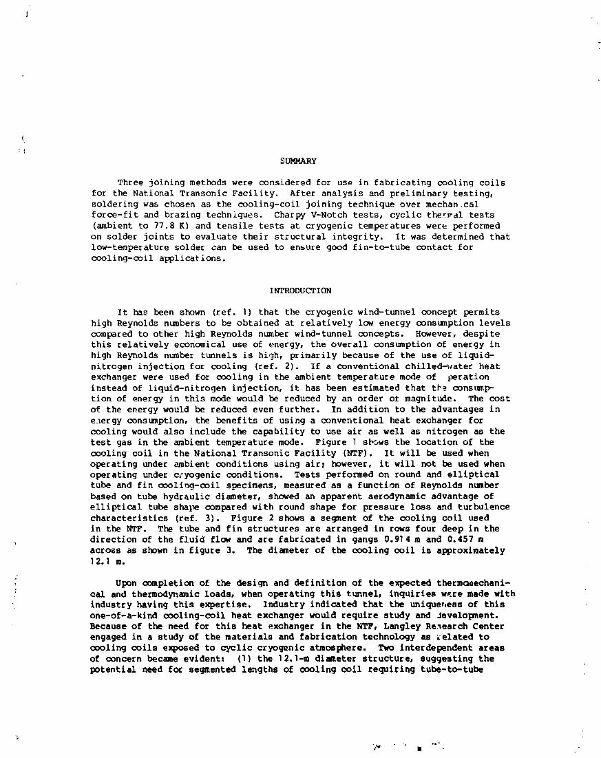
characteristics (ref. 3). Figure 2 shows a segment of the cooling coil used
in the NTF. The tube and fin structures are arranged in rows four deep in the
direction of the fluid flow and are fabricated in gangs 0.91 4 m and 0.457 m
across as shown in figure 3. The diameter of the cooling coil is approximately12.1 m.
Upon completion of the design and definition of the expected therm(_nechani-
cal and thermodynamic loads, when operating this tunnel, inquiries w_.re made with
industry having this expertise. Industry indicated that the uniqueness of this
one-of-a-kind cooling-coil heat exchanger would require study and Jevelopment.
Because of the need for this heat exchanger in the NTF, Langley Research Center
engaged in a study of the materials and fabrication technology as _elated to
cooling coils exposed to cyclic cryogenic atmosphere. Two interdependent areas
of concern became evident. (I) the 1 2.1-m diameter structure, suggesting the
potential need for segmented lengths of cooling coil requiring tube-to-tube
1980023982-003

joints and (2) the effect of cyclic thermal excursions at cryogenic temperatures
and the eff_ct of cryogenic to ambient temperatures on joints and joint bonding
materials.
JOINING METHODS AND MATERIALS
Table I shows the joining methods considered for fabricating the NTF cool-
ing coils. Mechanical force fit is the technique most commonly used in industry
to fabricate cooling coils. This method was ruled out early in the study when
analysis indicated that thermal cycling in a cryogenic atmosphere would loosen
the interface between the tube and fin components making up the cooling coil,
thereby decreasing the heat transfer efficiency of the system. A second method
eliminated early in the study was the dip brazing of aluminum (tables I and II).
This technique was dropped because of corrosion experienced with aluminum tubing
used in similar circumstances. Vacuum brazing of as-drawn (hard copper) oxygen-
free copper (tables I and If) brazed with an alloy composed of 72 percent silver
and 28 percent copper was accomplished in a vacuum braze furnace at
0.00]33 newton/ meter 2 at a maximum temperature of 1097.6 K. Figure 4 shows the
braze test specimen with fins, tubes, and joints. The joints were requireJ in
the specimen because joints would be needed in the full-scale cooling coil.
There are no vacuum braze furnaces in the United States capable of brazing a
cooling coil over ]2.l m in length with the configuration required for the NTF.
Finally, two low-temperature solders (table II) were also evaluated for joining
the as-drawn (hard copper) oxygen-free copper. The advantage of using low-
temperature solder was the availability of furnaces that would allow for fabri-
cating ]2.5-m-long (diameter) cooling coils. The two solders evaluated were
eutectic compositions as shown in figures 5 and 6. These eutectic alloys .=:_3w
melting temperatures of 494 K and 456 K, respectively, low enough not tc delet-
eriously affect the mechanical properties of the hard copper tubes and fins
being soldered. The low melting temperature of these alloys plus limited exper-
ience in their use at Langley were the reasons for evaluating them as candidate
joining materials. A major disadvantage when using high tin solders is the
brittleness of tb,_,sesolders when subjected to temperatures at and below their
ductile-brittle transition temperature of 173.6 K (ref. 4).
TEST AND PROCEDURE
Because of the problem of brittleness with tin solder and limited data on
materials subjected to the unique environmental regime of the NTF, a series of
quality tests were undertaken. Tensile load tests were performed on copper tube
specimens (fig. 7) joined at the center to evaluate solder alloy compositions
(table II) in cryogenic atmospheres. Cryogenic tensile tests were performed
in a cold-box tensile test facility. Cyclic cryogenic tests consisted of two
steps. Tensile specimens (fig. 7) were submerged in liquid nitrogen, held in
place until thermal equilibrium was reached, raised out of the nitrogen Into
a furnace at 355.6 K, and again held in position until thermal equilibrium was
reached. Then the cycle was repeated for a predetermined number of cycles.
Upon completion of the desired number of thermal cycles, the specimens were
i
1980023982-004

: removed from the thermal cycling system and tested (ambient conditions) in
tension in the tensile testing machine. Tensile tests were conducted at a
strain rate of 0.51 mm per minute. Thermal cycle tests made on a segment of
" the NTF cooling coil to evaluate the integrity of the fin-to-tube bond used the
thermal cyclic technique described previously for the tensile specimens
: (fig. 8). Upon completion of the thermal cycles, the specimen was examined with
a metallograph to observe the presenc _ of cracks at the fin-tube interface.
RESULTS AND DISCUSSION
As described previously in this paper, mechanical force-fit brazing and
dip brazing were eliminated after analysis of these techniques. Upon comple-
tion of vacuum brazing a hard copper specimen brazed with 72 percent silver and
28 perr:ent copper, this technique was dropped. The specimen shown in figure 9
was so ductile after brazing that it was determined that copper cooling coils
fabricated using this technique would be considered structurally unacceptable.
Because soldering would allow fabrication at low temperatures (453.6 K) and
eliminate the need for joints, it was considered the most promising method for
manufacture of the cooling coils. The solder material now had only one major
function and that was to maintain its thermal interface between cooling-coil
fin and tube when subjected, though not in use, to cryogenic cycling. Theresults of a literature search are summarized in table III. The data indicate
that solder alloys having a major tin constituent become brittle and eventually
crack when subjected to cyclic heating and cooling between 355.6 K and 77.8 K.
Charpy V-Notch tests were performed on the two solder alloys chosen for this
structure to substantiate data from the literature. The V-Notch tests showed
both alloys had acceptable toughness at room temperature but had very low impact
strength at 77.8 K.
Because the cooling coil would have no impact loads and would operate in
ambient conditions, several additional tests were performed to evaluate the
integrity of the tube-to-fin solder joint. Tensile load tests were performed
on copper tube specimens (fig. 7) joined at the center with the solder alloy
compositions shown in table If. Tensile tests were used as the criteria for
solder joint acceptability since a cracked spec_J,en, assuming a crack in the
solder joint resulted from specimen exposure to cycling at cryogenic tempera-
tures, would have a lower tensile strength than a specimen with no flaws. Fig-
ure 10 shows solder joint strength as a function of temperature. The curves
show the expected increase in strength to the ductile-brittle transition temper-
ature, where the strength then falls off (ref. 5). The important point observed
in these curves was that the solder joint strength (low notch toughness,
table IV) at cryogenic temperatures approximated or was stronger than the solder
= joint tested at room temperature (good notch toughness, table IV). Figure 11
shows joint strength of specimens pulled at ambient temperature after up to
5000 cyclic cryogenic exposures between 77.8 K and 355.6 K. Lines faired
through data points for the two solder alloys evaluated showed no appreciable
change in the strength of the solder joints. Finally, the typical segment of
a fin-tube cooling coil (fig. 8) cycled 5000 times between 77.8 K and 355.6 K
showed no cracks at the tube-fin interface when examined with a metallograph.
1980023982-005

CONCLUS IONS
The results of this study indicate the following conclusions:
[ ]. Cyclic cryogenic exposure did not affect the room-temperature strength
of the low-temperature solder joint.
2. The low-temperature solders in the joints tested did not show cracking
when submitted to cyclic exposure below their ductile-brittle transition
temperature.
3. Low-temperature solder can be used to ensure good fin-to-tube contactfor cooling-coil applications.
Langley Research Center
National Aeronautics and Space Administration
Hampton, VA 23665
August 27, ]980
REFERENCES
1. Kilgore, Robert A._ Goodyer, Michael J.; Adcock, Jerry B.; and Davenport,
Edwin E. : The Cryogenic Wind-Tunnel Concept for High Reynolds Number
Testing. NASA TN D-7762, ]974.
2. Polhamus, E. C._ Kilgore, R. A._ Adcock, J. B.; and Ray, E. J. : The Langley
Cryogenic High Reynolds Number Wind-Tunnel Program, Astronaut. & Aeronaut.,vol. ]2, no. 10, Oct. 1974, pp. 30-40.
3. Johnson, William G., Jr.; and Igoe, William B.: Aerodynamic ChaEacteristicsat Low Reynolds Numbers of Several Heat-Exchanger Configurations for Wind-Tunnel Use. NASA TM-801 88, 1979.
4. Hansen, Max: Constitution of Binary Alloys. Second ed. McGraw-Hill BookCo., Inc., 1958.
r
5. Jaffee, R. I._ Minarcik, E. J.; and Gonser, B. W." Low-Temperature Proper-ties of Lead-Base Solders and Soldered Joints. Metals Progr., vol. 54,
no. 6, Dec. ]948, pp. 843-845.
4
L _t
L
1980023982-006

TABLE I.- JOINING METHODS
• MECHANICALFORCEFIT
• BRAZING
A. DIP BRAZING
B. VACUUMFURNACEBRAZING
• SOLDERING
A. 95"/oTIN-5"/,,SILVER
B. 63%TIN - 37%LEAD
TABLE II.- COOLING-COIL MATERIALS
TUBEANDFIN BRAZE SOLDER JOININGALLOYS ALLOYS ALLOYS TECHNIQUES
6061ALUMINUM 89%ALUMINUM DIP BRAZING11%SILICON
OXYGENFREE 72%SILVER VACUUM BRAZE
COPPER 28%COPPER (HARD-COPPER)
- { 95%TINOXYGENFREE .5%SILVER LOWTEMPERATUREFURNACESOLDER
COPPER ,r 63%TIN (HARD-COPPER)L 37%LEAD
1980023982-007

TABLE III.- SOLDER DATA - ELECTRICAL OONNECTIONS
• TIN SOLDERTESTS
--63TIN - 37 LEAD
--95TIN - 5 ANTIMONY
• CYCLEDBETWEEN77.8 K AND 355.6K
• SOLDERWIRECONNECTIONSBECAMEBRITTLEANDDEVELOPEDCRACKSRESULTINGIN NOISY ELECTRICALOUTPUT
TABLE IV.- ASTM CHARPY V-NOTCH TEST DATA
SOLDERMATERIALS
QUANTITY 95"IoTIN-5%SILVER 03%TIN-37%LEAD
TEMPERATURE,K IMPACT VALUE, J IMPACT VALUE, J
ROC)MTEMP. 6 51.68 25.84
: 355.6 6 51.68 25.84
77.8 6 .544 1.22
6
la,
1980023982-008

%
a
COOLINGCOIL-_'_-J_J-J_ "
Figure l.- Location of cooling coils in NTF.
0.026 m -_/ ELLIPTICALTUBE
0.014 m x 0.036m
0.055m 0.001m WALL
FIN
0.0003 m THICK
._L
0.003m
FLOW
¢.
Figure 2.- Fin-tul:_ concept: showing section of _ _oILn_ coil.
1980023982-009

t
TYPICALCOILBUNDtE
I r FLOWLINER
I1 DIAM ll rn_"- -- SHELL3I- DIAM 12.5 m
Figure 3.- Cross section of NTF tunnelshowing cooling coil.
_>i. lt+J
I
Ii!) II smm i
L-80-192
Piqure 4.- Braze teat apeoilen shovingfln-to-tube and tube-to-tube Jolnta.
h
1980023982-010

" 1273
1173 '_'_!-\_233K
"_ LIQUID & SOLID1073-
_ _TK LIQUID
"- so:,L '°"<273_ _zL__LL'._-I___L__:.I_:_L-_- :1:__-J:_: -__i
0 I0 20 30 40 50 60 70 80 90 100
Ag ATOMICPERCENTTIN Sn
L___].___[ l L ! L [ I [ J0 l0 20 -30 40 50 60 70 80 90 I00
WEIGHTPERCENTTIN
Figure 5.- Equilibrium phase diagram for silver-tin (ref. 4).
623
513 _6_ K
L,QU,D_i /
'2_'so'K T_ /M_ \tu.c uIo_soL,oTE,_lPERATURE. LIQUID& SOLID (Pb)
K 423 _ (Sn) _
373
323 SOLID- 273 __ _ ___Z _I I . J. JJ. 20 40 60 80 100
Sn ATOMI_PERCENTLEAD Pb
i I I I l [, I i I 1 I I_ )lO 20 30 40 50 60 70 80 85 gO 95 lO0
WEIGHTPERCEr_TLEAD
Figure 6.- _Juillbri_ phase diagram for tin-lead (ref. 4).
1980023982-011

.....0.016m "--0.0012m. . . . .
-I L Lo.oo_m---- 0.008m
Figure 7.- Copper tube solder joint ten._'_ile load test specimen.
J
5000CYCLESBEWJEEN
77.8K AND355.6K
?igure 8.- NT? oooling-ooll therIal-aycle test specLien.
10
1980023982-012

L-80-, _J
Figure 9.- Tube and fin specimen after
vacuum braze at 1097.6 K.
2250-
2000 © 95_Sn-5%Ag CuTUBEANNEALEDI097.6K
_ 95%Sn-5%AQ CuTUBEANNEALED??.6K'_ 63%Sn-37 PD CuTUBEANNEA[ED:_37.6K
FAILURE.
kg 1ooo OP-'IGI_'qAL PAGE --
II-- DUCTILE-BRITTLETRANSITIONTEMPERATUREI
i I I I I0 100 200 300 400
TEMPERATURE.K
Figure I0.- Solder Joint atre._gth as a function of tmpetatute.
11
1980023982-013

1700-
0 95%Sn 5%Ag1500 - [] 63%Sn 37%Pb
.x 95%Sn 5%Ag NOCYCLESLOADTO O
FAILURE, O Okg I000 x--Cr--O O O O
[]
500 -
I I I I t0 1000 2000 3000 4000 5000
.
THERMAL CYCLES BETWEEN77.8K AND 355.6K
Figure ll.- Solder joint strength pulled at ambient temperature after
thermal cycllc exposure between 77.8 K and 355.6 K.
12
+
, + • ,
1980023982-014