Embed Size (px)
Citation preview

1 IntroductionThis document describes the use of coin cell batteries for lowpower ZigBee connectivity applications. Implementation of anapplication operated by a coin cell battery brings with it manyconstraints, especially when peak currents can attain relativelyhigh values of the order of 30 mA during radio reception andtransmission. The coin cell battery used for testing was thevery popular CR2032, which is often used for small/lowpower applications. It is well known the CR2032 is able tosupport operating loads of a few mA. Furthermore, smalllinear currents are sufficiently well specified by the batterymanufacturer data sheets. However, the use case involvinghigh transient peak currents is not well described in terms ofthe effect on battery lifetime. This application note coverspractical experiments with ZigBee wireless applicationsrunning on Freescale’s MC1323x integrated radio platform,powered by a coin cell battery.
The application was configured to periodically transmit burstsof data, and consequently the battery was stressed by the highpeak current drawn. A series of tests were made to investigatethe use of a coin cell battery power supply for ZigBee radioapplications. Results are presented and a feasibility analysis ismade concerning the use case. This analysis could equally beapplied to other types of low power wireless connectivity, forexample BLE (Bluetooth Low Energy), where similar peak/transient demands are made on the battery.
Freescale Semiconductor Document Number:AN4573
Application Note Rev. 0, August 2012
Low Power Considerations forZigBee Applications Operated byCoin Cell Batteriesby: Karel Povalac and Peter Ligertwood
Freescale Applications
© 2012 Freescale Semiconductor, Inc.
Contents
1 Introduction................................................................1
2 MC1323x overview...................................................2
2.1 Feature summary............................................3
2.2 MC1323x operating modes............................3
2.3 MC1323x low power modes..........................4
2.4 1323x-IPB Small form factorreference design.............................................4
3 Coin cell battery considerations................................5
4 Battery lifetime estimation........................................5
4.1 Peak current considerations...........................6
4.2 Parallel capacitor calculation.........................8
5 Experimental results.................................................9
5.1 Measurement setup.........................................9
5.2 Measured results............................................9
5.3 Mitigation techniques and bestpractices.......................................................11
6 References...............................................................11
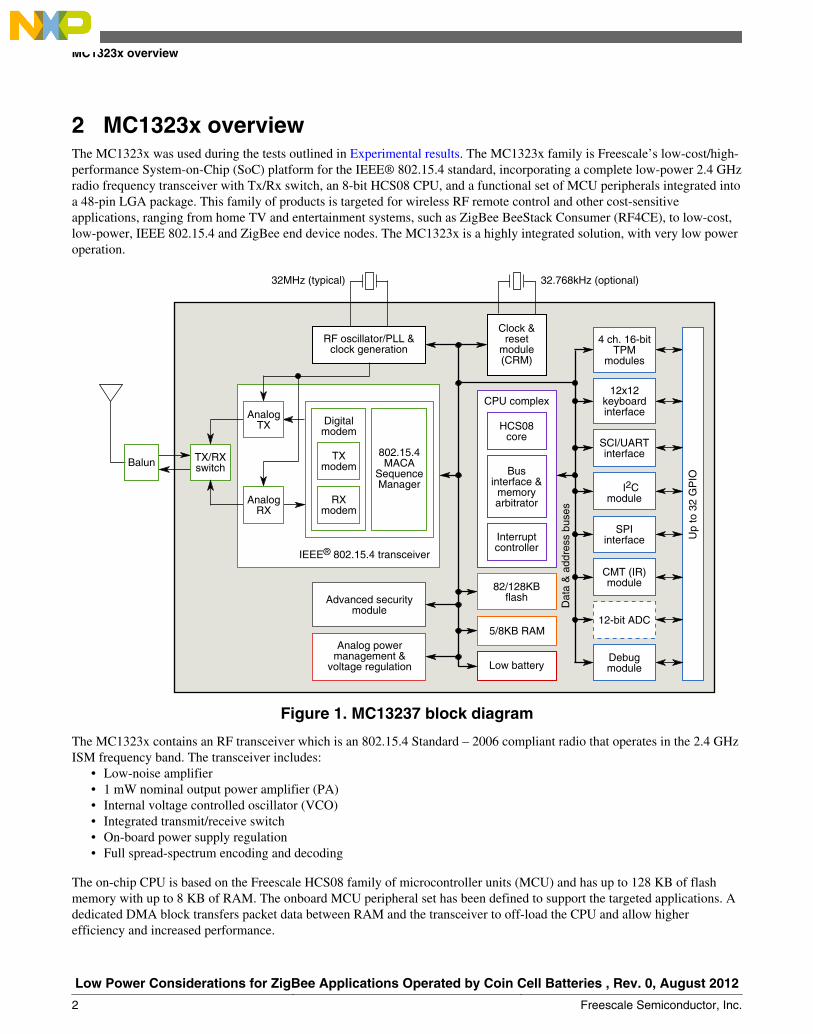
2 MC1323x overviewThe MC1323x was used during the tests outlined in Experimental results. The MC1323x family is Freescale’s low-cost/high-performance System-on-Chip (SoC) platform for the IEEE® 802.15.4 standard, incorporating a complete low-power 2.4 GHzradio frequency transceiver with Tx/Rx switch, an 8-bit HCS08 CPU, and a functional set of MCU peripherals integrated intoa 48-pin LGA package. This family of products is targeted for wireless RF remote control and other cost-sensitiveapplications, ranging from home TV and entertainment systems, such as ZigBee BeeStack Consumer (RF4CE), to low-cost,low-power, IEEE 802.15.4 and ZigBee end device nodes. The MC1323x is a highly integrated solution, with very low poweroperation.
32.768kHz (optional)32MHz (typical)
TX/RXswitch
TXmodem
802.15.4MACA
SequenceManager
Digitalmodem
RXmodem
IEEE® 802.15.4 transceiver
RF oscillator/PLL &clock generation
Clock &reset
module(CRM)
Advanced securitymodule
Analog powermanagement &
voltage regulation
Up
to 3
2 G
PIO
Dat
a &
add
ress
bus
es
AnalogTX
AnalogRX
4 ch. 16-bitTPM
modules
12x12keyboardinterface
SCI/UARTinterface
I2Cmodule
SPIinterface
CMT (IR)module
12-bit ADC
Debugmodule
HCS08core
CPU complex
Businterface &
memoryarbitrator
Interruptcontroller
82/128KBflash
Low battery
5/8KB RAM
Balun
Figure 1. MC13237 block diagram
The MC1323x contains an RF transceiver which is an 802.15.4 Standard – 2006 compliant radio that operates in the 2.4 GHzISM frequency band. The transceiver includes:
• Low-noise amplifier• 1 mW nominal output power amplifier (PA)• Internal voltage controlled oscillator (VCO)• Integrated transmit/receive switch• On-board power supply regulation• Full spread-spectrum encoding and decoding
The on-chip CPU is based on the Freescale HCS08 family of microcontroller units (MCU) and has up to 128 KB of flashmemory with up to 8 KB of RAM. The onboard MCU peripheral set has been defined to support the targeted applications. Adedicated DMA block transfers packet data between RAM and the transceiver to off-load the CPU and allow higherefficiency and increased performance.
MC1323x overview
Low Power Considerations for ZigBee Applications Operated by Coin Cell Batteries , Rev. 0, August 2012
2 Freescale Semiconductor, Inc.
2.1 Feature summary• MCU Features
• Integrated HC9S08 8-bit up to 32 MHz• Memory
• MC13237: 128 KB flash memory and 8 KB RAM• MC13233: 82 KB flash memory and 5 KB RAM
• Peripherals• SCI• SPI• I2C• Up to 12×12 KBI
• Carrier-modulated timer (IR)• Up to 32 general ourpose input/output ports (GPIO)• 12-bit ADC (on MC13237)
• Radio Features• Programmable transmit from –30 dBm to +2 dBm• Receive sensitivity of –94 dBm• <31 mA receive and 27 mA transmit with radio and MCU• 802.15.4 compliant 2.4 GHz RF transceiver• Auto-trim feature for crystal accuracy• Integrated transmit/receive switch
• General Features• Power supply range: 1.8–3.4 V• AES 128-bit hardware encryption/decryption• 7 mm × 7 mm 48-pin LGA• Operating temperature range: –40 °C to 85 °C
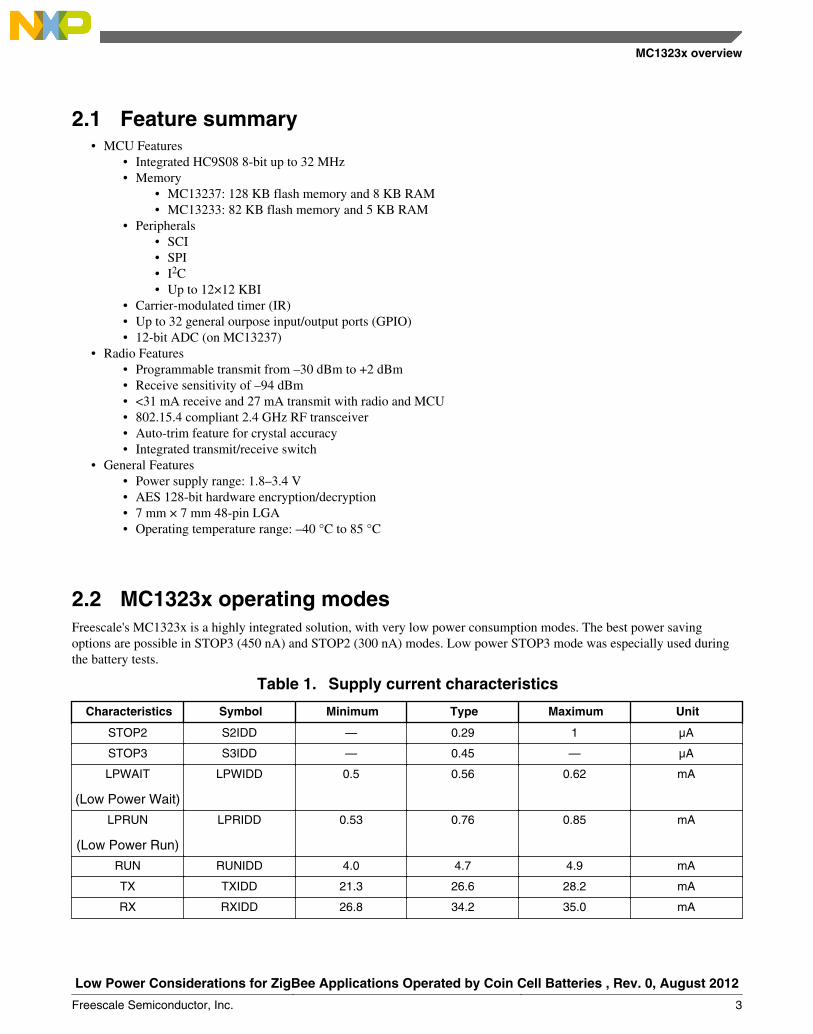
2.2 MC1323x operating modesFreescale's MC1323x is a highly integrated solution, with very low power consumption modes. The best power savingoptions are possible in STOP3 (450 nA) and STOP2 (300 nA) modes. Low power STOP3 mode was especially used duringthe battery tests.
Table 1. Supply current characteristics
Characteristics Symbol Minimum Type Maximum Unit
STOP2 S2IDD — 0.29 1 µA
STOP3 S3IDD — 0.45 — µA
LPWAIT
(Low Power Wait)
LPWIDD 0.5 0.56 0.62 mA
LPRUN
(Low Power Run)
LPRIDD 0.53 0.76 0.85 mA
RUN RUNIDD 4.0 4.7 4.9 mA
TX TXIDD 21.3 26.6 28.2 mA
RX RXIDD 26.8 34.2 35.0 mA
MC1323x overview
Low Power Considerations for ZigBee Applications Operated by Coin Cell Batteries , Rev. 0, August 2012
Freescale Semiconductor, Inc. 3
Typical radio and MCU power consumption specified values are presented in Table 1. (For more information, see items 1and 2 in References.) These values were used for the battery lifetime calculations which follow. It is evident from the tablethat the most stressful situation for the battery is when transmitting and receiving bursts of data.
2.3 MC1323x low power modesA summary of MC1323x operating modes is described below. There are a number of different operating modes for thisdevice. (For more information, see item 2 in References.)
• STOP modes — System clocks are stopped and voltage regulator is in standby.• STOP2 — Partial power down of internal circuits, RAM content is retained; I/O states are held.• STOP3 — All internal circuits are powered for fast recovery (32 MHz oscillator on-off optional).
• LPRun mode — CPU clock is set to 500 kHz and peripheral clocks (bus clock) to 250 kHz. The internal voltageregulator is in standby.
• Wait mode — CPU shuts down to conserve power. System clocks are running and full regulation is maintained.• LPWait mode — CPU shuts down to conserve power; peripheral clocks are restricted to 250 kHz and the internal
voltage regulator is in standby.• Run mode — CPU clocks can run at full speed and the internal supply is fully regulated.
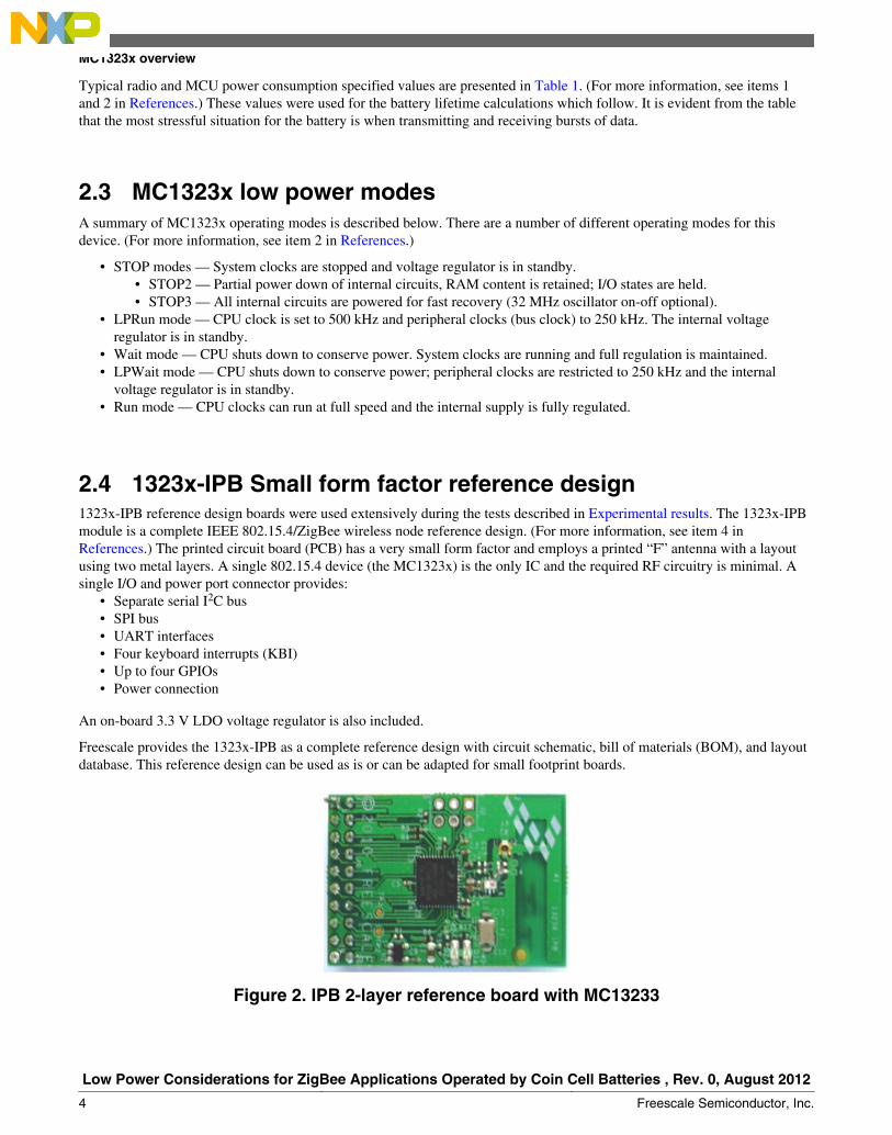
2.4 1323x-IPB Small form factor reference design1323x-IPB reference design boards were used extensively during the tests described in Experimental results. The 1323x-IPBmodule is a complete IEEE 802.15.4/ZigBee wireless node reference design. (For more information, see item 4 inReferences.) The printed circuit board (PCB) has a very small form factor and employs a printed “F” antenna with a layoutusing two metal layers. A single 802.15.4 device (the MC1323x) is the only IC and the required RF circuitry is minimal. Asingle I/O and power port connector provides:
• Separate serial I2C bus• SPI bus• UART interfaces• Four keyboard interrupts (KBI)• Up to four GPIOs• Power connection
An on-board 3.3 V LDO voltage regulator is also included.
Freescale provides the 1323x-IPB as a complete reference design with circuit schematic, bill of materials (BOM), and layoutdatabase. This reference design can be used as is or can be adapted for small footprint boards.
Figure 2. IPB 2-layer reference board with MC13233
MC1323x overview
Low Power Considerations for ZigBee Applications Operated by Coin Cell Batteries , Rev. 0, August 2012
4 Freescale Semiconductor, Inc.
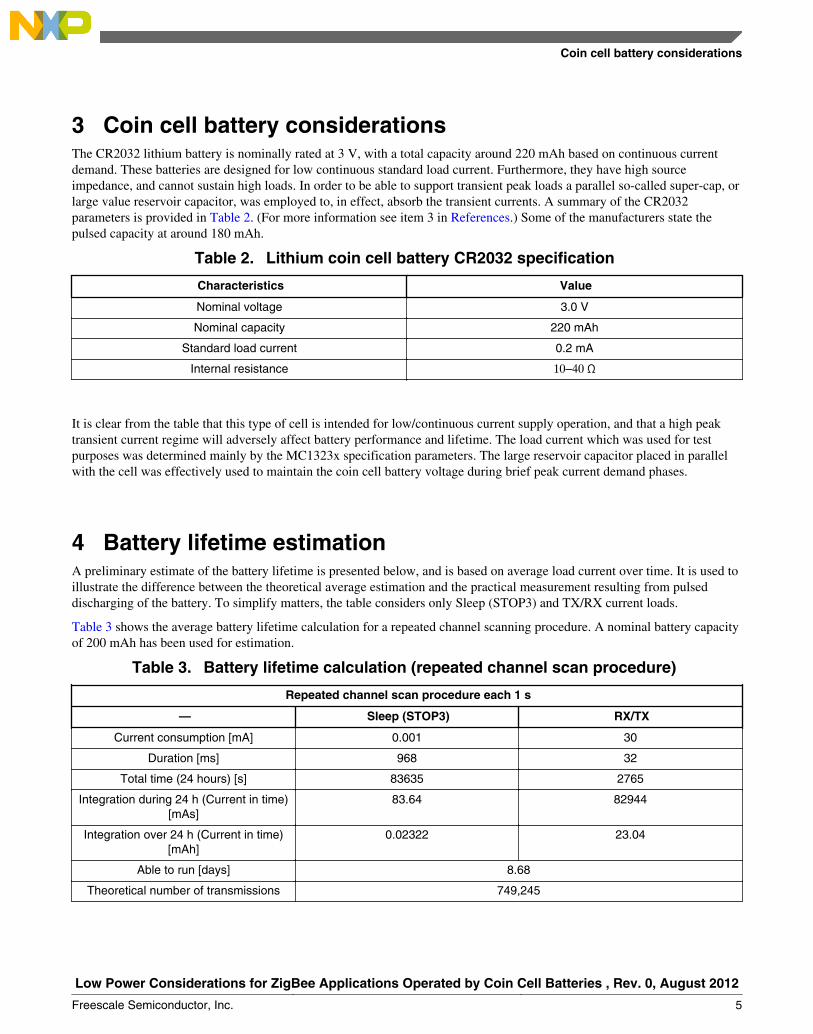
3 Coin cell battery considerationsThe CR2032 lithium battery is nominally rated at 3 V, with a total capacity around 220 mAh based on continuous currentdemand. These batteries are designed for low continuous standard load current. Furthermore, they have high sourceimpedance, and cannot sustain high loads. In order to be able to support transient peak loads a parallel so-called super-cap, orlarge value reservoir capacitor, was employed to, in effect, absorb the transient currents. A summary of the CR2032parameters is provided in Table 2. (For more information see item 3 in References.) Some of the manufacturers state thepulsed capacity at around 180 mAh.
Table 2. Lithium coin cell battery CR2032 specification
Characteristics Value
Nominal voltage 3.0 V
Nominal capacity 220 mAh
Standard load current 0.2 mA
Internal resistance 10–40 Ω
It is clear from the table that this type of cell is intended for low/continuous current supply operation, and that a high peaktransient current regime will adversely affect battery performance and lifetime. The load current which was used for testpurposes was determined mainly by the MC1323x specification parameters. The large reservoir capacitor placed in parallelwith the cell was effectively used to maintain the coin cell battery voltage during brief peak current demand phases.
4 Battery lifetime estimationA preliminary estimate of the battery lifetime is presented below, and is based on average load current over time. It is used toillustrate the difference between the theoretical average estimation and the practical measurement resulting from pulseddischarging of the battery. To simplify matters, the table considers only Sleep (STOP3) and TX/RX current loads.
Table 3 shows the average battery lifetime calculation for a repeated channel scanning procedure. A nominal battery capacityof 200 mAh has been used for estimation.
Table 3. Battery lifetime calculation (repeated channel scan procedure)
Repeated channel scan procedure each 1 s
— Sleep (STOP3) RX/TX
Current consumption [mA] 0.001 30
Duration [ms] 968 32
Total time (24 hours) [s] 83635 2765
Integration during 24 h (Current in time)[mAs]
83.64 82944
Integration over 24 h (Current in time)[mAh]
0.02322 23.04
Able to run [days] 8.68
Theoretical number of transmissions 749,245
Coin cell battery considerations
Low Power Considerations for ZigBee Applications Operated by Coin Cell Batteries , Rev. 0, August 2012
Freescale Semiconductor, Inc. 5
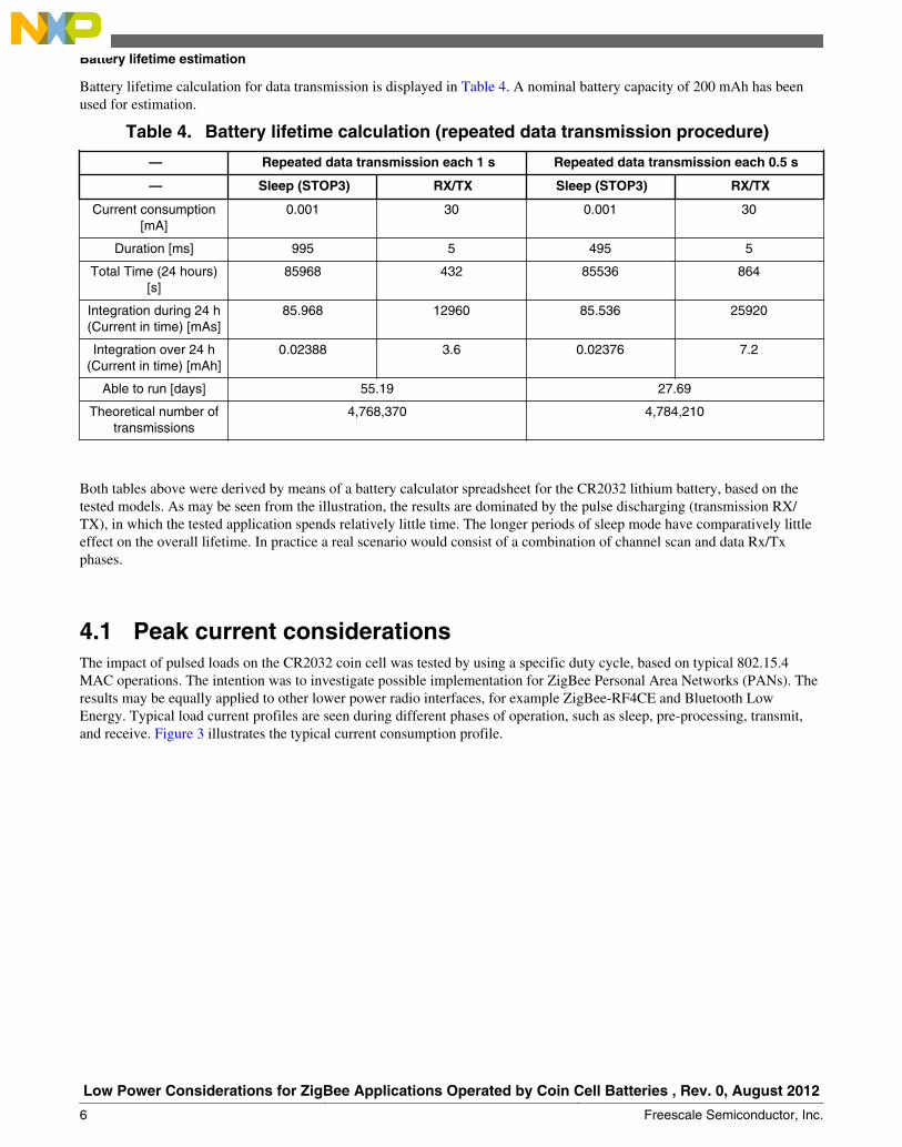
Battery lifetime calculation for data transmission is displayed in Table 4. A nominal battery capacity of 200 mAh has beenused for estimation.
Table 4. Battery lifetime calculation (repeated data transmission procedure)
— Repeated data transmission each 1 s Repeated data transmission each 0.5 s
— Sleep (STOP3) RX/TX Sleep (STOP3) RX/TX
Current consumption[mA]
0.001 30 0.001 30
Duration [ms] 995 5 495 5
Total Time (24 hours)[s]
85968 432 85536 864
Integration during 24 h(Current in time) [mAs]
85.968 12960 85.536 25920
Integration over 24 h(Current in time) [mAh]
0.02388 3.6 0.02376 7.2
Able to run [days] 55.19 27.69
Theoretical number oftransmissions
4,768,370 4,784,210
Both tables above were derived by means of a battery calculator spreadsheet for the CR2032 lithium battery, based on thetested models. As may be seen from the illustration, the results are dominated by the pulse discharging (transmission RX/TX), in which the tested application spends relatively little time. The longer periods of sleep mode have comparatively littleeffect on the overall lifetime. In practice a real scenario would consist of a combination of channel scan and data Rx/Txphases.
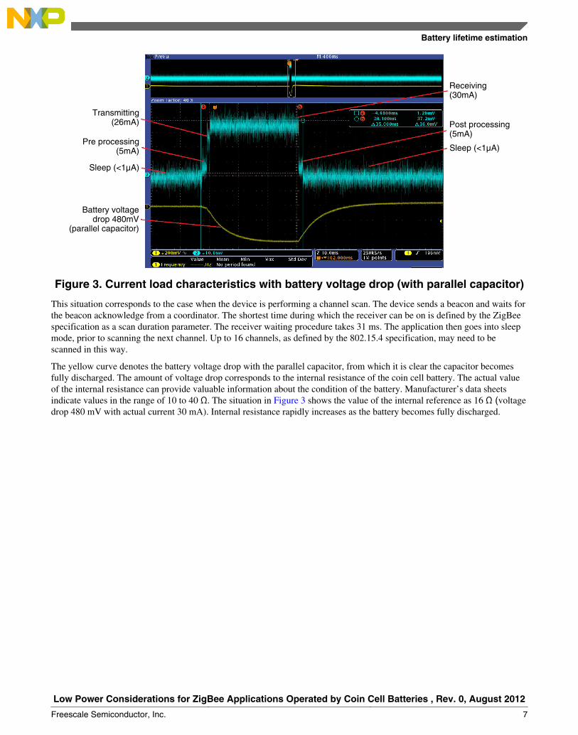
4.1 Peak current considerationsThe impact of pulsed loads on the CR2032 coin cell was tested by using a specific duty cycle, based on typical 802.15.4MAC operations. The intention was to investigate possible implementation for ZigBee Personal Area Networks (PANs). Theresults may be equally applied to other lower power radio interfaces, for example ZigBee-RF4CE and Bluetooth LowEnergy. Typical load current profiles are seen during different phases of operation, such as sleep, pre-processing, transmit,and receive. Figure 3 illustrates the typical current consumption profile.
Battery lifetime estimation
Low Power Considerations for ZigBee Applications Operated by Coin Cell Batteries , Rev. 0, August 2012
6 Freescale Semiconductor, Inc.
Transmitting(26mA)
Pre processing(5mA)
Sleep (<1µA)
Battery voltagedrop 480mV
(parallel capacitor)
Sleep (<1µA)
Post processing(5mA)
Receiving(30mA)
Figure 3. Current load characteristics with battery voltage drop (with parallel capacitor)
This situation corresponds to the case when the device is performing a channel scan. The device sends a beacon and waits forthe beacon acknowledge from a coordinator. The shortest time during which the receiver can be on is defined by the ZigBeespecification as a scan duration parameter. The receiver waiting procedure takes 31 ms. The application then goes into sleepmode, prior to scanning the next channel. Up to 16 channels, as defined by the 802.15.4 specification, may need to bescanned in this way.
The yellow curve denotes the battery voltage drop with the parallel capacitor, from which it is clear the capacitor becomesfully discharged. The amount of voltage drop corresponds to the internal resistance of the coin cell battery. The actual valueof the internal resistance can provide valuable information about the condition of the battery. Manufacturer’s data sheetsindicate values in the range of 10 to 40 Ω. The situation in Figure 3 shows the value of the internal reference as 16 Ω (voltagedrop 480 mV with actual current 30 mA). Internal resistance rapidly increases as the battery becomes fully discharged.
Battery lifetime estimation
Low Power Considerations for ZigBee Applications Operated by Coin Cell Batteries , Rev. 0, August 2012
Freescale Semiconductor, Inc. 7

Figure 4. Current load characteristics with battery voltage drop (without parallelcapacitor)
Voltage drop without parallel capacitor is shown in Figure 4, using the same beacon request scenario. (In this case the testedbattery was brand new, which explains why the value of the voltage drop (300 mV) is smaller.)
Another experiment covers the situation when the transmitting and receiving window is shorter (5 ms) with the same currentload. This corresponds to the situation when the ZigBee End Device needs to transmit (for example) 100 bytes of data. In thiscase the parallel reservoir capacitor is not fully discharged during the data transmission, as was the case in the previousscenario.
4.2 Parallel capacitor calculationIn this section, we provide an example calculation of how the parallel capacitor is able to maintain output voltage while understress by the peak load current. A typical 802.15.4 MAC level interaction is used to illustrate the case.
To determine the drop in supply voltage from the capacitor:
Where: C = 470 μF, i = 30 mA, Δt = 35 ms.
The resulting voltage drop would be:
Looking at it another way, it is possible to determine how long the capacitor can hold up before the voltage collapses to apoint where the MCU would be forced to reset.
Where Δu is assumed to be 1.2 V; nominal supply is 3 V and minimum voltage for the MC1323x is 1.8 V, as given in thespecification.
Therefore
Battery lifetime estimation
Low Power Considerations for ZigBee Applications Operated by Coin Cell Batteries , Rev. 0, August 2012
8 Freescale Semiconductor, Inc.
This demonstrates that use of a large reservoir capacitor can support typical 802.15.4 MAC interactions. If multipleinteractions are required, then it is necessary for the device to go to standby mode for a recovery period. The reservoircapacitor can easily support the battery during the non-continuous short data transmission process, for example, 5 ms bursts.However in the longer term, the transmissions will definitely cause the battery voltage level to drop, as determined by theinternal battery resistance, which increases as the battery nears the end of its life. The choice of capacitor value is ultimatelydependent on the demands of the application.
Another factor to take into account is capacitor leakage current, which can also decrease battery lifetime. The capacitorleakage current can continuously discharge the battery and depends on factors such as the capacitor value, the nominalvoltage rating, and the production process technology used.
5 Experimental resultsSeveral test scenarios were considered in order to obtain a realistic expectation of the battery lifetime, for the peak transientcurrent use case. Practical measurements were required to be able to assess whether or not the coin cell could withstand theanticipated discharge characteristics. The sections below illustrate the practical measurement results.
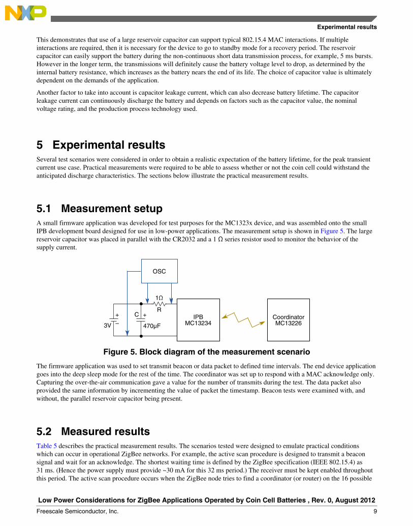
5.1 Measurement setupA small firmware application was developed for test purposes for the MC1323x device, and was assembled onto the smallIPB development board designed for use in low-power applications. The measurement setup is shown in Figure 5. The largereservoir capacitor was placed in parallel with the CR2032 and a 1 Ω series resistor used to monitor the behavior of thesupply current.
CoordinatorMC13226
IPBMC13234470µF
C ++
3V
OSC
1Ω
R
–
Figure 5. Block diagram of the measurement scenario
The firmware application was used to set transmit beacon or data packet to defined time intervals. The end device applicationgoes into the deep sleep mode for the rest of the time. The coordinator was set up to respond with a MAC acknowledge only.Capturing the over-the-air communication gave a value for the number of transmits during the test. The data packet alsoprovided the same information by incrementing the value of packet the timestamp. Beacon tests were examined with, andwithout, the parallel reservoir capacitor being present.
5.2 Measured resultsTable 5 describes the practical measurement results. The scenarios tested were designed to emulate practical conditionswhich can occur in operational ZigBee networks. For example, the active scan procedure is designed to transmit a beaconsignal and wait for an acknowledge. The shortest waiting time is defined by the ZigBee specification (IEEE 802.15.4) as31 ms. (Hence the power supply must provide ~30 mA for this 32 ms period.) The receiver must be kept enabled throughoutthis period. The active scan procedure occurs when the ZigBee node tries to find a coordinator (or router) on the 16 possible
Experimental results
Low Power Considerations for ZigBee Applications Operated by Coin Cell Batteries , Rev. 0, August 2012
Freescale Semiconductor, Inc. 9
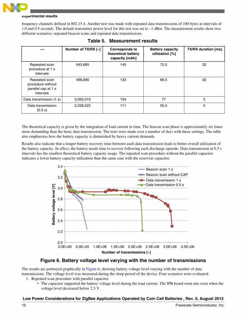
frequency channels defined in 802.15.4. Another test was made with repeated data transmissions of 100 bytes at intervals of1.0 and 0.5 seconds. The default transmitter power level for this test was set to –1 dBm. The measurement results show twodifferent scenarios: repeated beacon scans and repeated data transmissions.
Table 5. Measurement results
— Number of TX/RX [–] Corresponds totheoretical battery
capacity [mAh]
Battery capacityutilization [%]
TX/RX duration [ms]
Repeated scanprocedure at 1 s
intervals
543,685 145 72.5 32
Repeated scanprocedure withoutparallel cap at 1 s
intervals
498,990 133 66.5 32
Data transmission (1 s) 3,055,015 154 77 5
Data transmission(0.5 s)
2,228,022 111 55.5 5
The theoretical capacity is given by the integration of load current in time. The beacon scan phase is approximately six timesmore demanding than the basic data transmission. The tests were made over a number of days with these settings. The tablealso emphasizes how the battery capacity is diminished by heavy current demands.
Results also indicate that a longer battery recovery time between each data transmission leads to better overall utilization ofthe battery capacity. In effect, the battery needs time to recover following each discharge episode. Data transmission at 0.5 sintervals has the smallest theoretical battery capacity usage. The repeated scan procedure without the parallel capacitorindicates a lower battery capacity utilization than the same case with the reservoir capacitor.
5.0E+05 1.0E+06 1.5E+06 2.0E+06 2.5E+06 3.0E+06 3.5E+062.00.0E+00
2.2
2.4
2.6
2.8
3.0
3.2
3.4Beacon scan 1 s
Beacon scan without CAP
Data transmission 1 s
Number of transmissions [–]
Bat
tery
vo
ltag
e le
vel [
V] Data transmission 0.5 s
Figure 6. Battery voltage level varying with the number of transmissions
The results are portrayed graphically in Figure 6, showing battery voltage level varying with the number of datatransmissions. The voltage level was measured during the sleep period of the device. Four scenarios were evaluated:
1. Repeated scan procedure with parallel capacitor• The capacitor supported the battery voltage level during the load current. The IPB board went into reset when the
voltage level decreased below 2.3 V.
Experimental results
Low Power Considerations for ZigBee Applications Operated by Coin Cell Batteries , Rev. 0, August 2012
10 Freescale Semiconductor, Inc.

2. Repeated scan procedure without parallel capacitor• When the battery voltage level fell under 2.8 V, the voltage drop had a large impact (increasing the value of
internal resistance) and caused the reset of the device (1.8 V limit).3. Data transmission of 100 bytes at 1 s intervals with the parallel capacitor
• This test case had the best results overall, with respect to the battery capacity utilization. The board went intoreset when the voltage level dropped below 2.3 V.
4. Data transmission of 100 bytes at 0.5 s intervals with the parallel capacitor• This scenario indicates the lowest battery utilization, probably caused by the reduced recovery time.
These experimental measurements provide a clear picture of how the coin cell behaves under pulsed discharge conditions.Preliminary optimistic estimates given by integration of load current in time were compared with the actual measured results.The best case result of battery utilization (77 %) was found to be that for data transmission at 1 s intervals. The nominalcapacity of 200 mAh as specified by battery manufacturers corresponds to the 100 % level.
The value of voltage drop corresponds to the state of actual internal resistance. Practical tests demonstrate the voltagedropped during the period under observation, from approximately 120 mV to 1100 mV. The use of the parallel capacitorsignificantly affects the rate at which the internal resistance increases.
5.3 Mitigation techniques and best practicesIn the foregoing sections it was shown how a Freescale RF transceiver node (MC1323x) could be powered from a CR2032coin cell for use with typical ZigBee radio operations. Based on actual laboratory measurements made, it is possible to infer anumber of recommendations on how to obtain the best possible usage from the battery.
• A good indication of the state of the battery can be seen via the measure of internal battery resistance. This has a directcorrespondence to the voltage difference across the battery terminals, between loaded and unloaded conditions. It isproportional to the remaining battery capacity and, as was seen, increases rapidly as the battery nears the end of life.
• Coin cells work best with more constant, lower current demand, than with high peak transient currents. Battery capacityis significantly reduced by this type of usage.
• Use of a large value reservoir capacitor can help to absorb the transient peaks and hence protect the battery and helpmaintain mAh capacity.
• When selecting a reservoir capacitor, a low leakage value is very important.• Short peak current transients, followed by long recovery times, are better for a coin cell battery. For example, channel
scan for 30 ms @ 30 mA, followed by 0.5 to 1.0 seconds in Stop mode, will allow ample time for the battery torecover.
• Close attention needs to be paid to the MCU firmware configuration when in Stop mode, to avoid any possibility offloating pins. All ports not in use must be grounded to avoid this situation.
6 References1. Freescale document MC1323x, "MC1323x Low Cost SoC Remote Control Platform for the 2.4 GHz IEEE® 802.15.4
Standard"2. Freescale document MC1323xRM, MC1323x ZigBee™- Compliant Platform 2.4 GHz Low Power Transceiver for the
IEEE® 802.15.4 Standard plus Microcontroller Reference Manual3. Energizer CR2032 battery data sheet4. Freescale document 1323xIPBRM, 1323x-IPB Reference Design Reference Manual, Rev. 1.0
References
Low Power Considerations for ZigBee Applications Operated by Coin Cell Batteries , Rev. 0, August 2012
Freescale Semiconductor, Inc. 11
How to Reach Us:
Home Page:www.freescale.com
Web Support:http://www.freescale.com/support
USA/Europe or Locations Not Listed:Freescale SemiconductorTechnical Information Center, EL5162100 East Elliot RoadTempe, Arizona 85284+1-800-521-6274 or +1-480-768-2130www.freescale.com/support
Europe, Middle East, and Africa:Freescale Halbleiter Deutschland GmbHTechnical Information CenterSchatzbogen 781829 Muenchen, Germany+44 1296 380 456 (English)+46 8 52200080 (English)+49 89 92103 559 (German)+33 1 69 35 48 48 (French)www.freescale.com/support
Japan:Freescale Semiconductor Japan Ltd.HeadquartersARCO Tower 15F1-8-1, Shimo-Meguro, Meguro-ku,Tokyo 153-0064Japan0120 191014 or +81 3 5437 [email protected]
Asia/Pacific:Freescale Semiconductor China Ltd.Exchange Building 23FNo. 118 Jianguo RoadChaoyang DistrictBeijing 100022China+86 10 5879 [email protected]
Document Number: AN4573Rev. 0, August 2012
Information in this document is provided solely to enable system and softwareimplementers to use Freescale Semiconductors products. There are no express or impliedcopyright licenses granted hereunder to design or fabricate any integrated circuits orintegrated circuits based on the information in this document.
Freescale Semiconductor reserves the right to make changes without further notice to anyproducts herein. Freescale Semiconductor makes no warranty, representation, orguarantee regarding the suitability of its products for any particular purpose, nor doesFreescale Semiconductor assume any liability arising out of the application or use of anyproduct or circuit, and specifically disclaims any liability, including without limitationconsequential or incidental damages. "Typical" parameters that may be provided inFreescale Semiconductor data sheets and/or specifications can and do vary in differentapplications and actual performance may vary over time. All operating parameters,including "Typicals", must be validated for each customer application by customer'stechnical experts. Freescale Semiconductor does not convey any license under its patentrights nor the rights of others. Freescale Semiconductor products are not designed,intended, or authorized for use as components in systems intended for surgical implantinto the body, or other applications intended to support or sustain life, or for any otherapplication in which failure of the Freescale Semiconductor product could create asituation where personal injury or death may occur. Should Buyer purchase or useFreescale Semiconductor products for any such unintended or unauthorized application,Buyer shall indemnify Freescale Semiconductor and its officers, employees, subsidiaries,affiliates, and distributors harmless against all claims, costs, damages, and expenses, andreasonable attorney fees arising out of, directly or indirectly, any claim of personal injuryor death associated with such unintended or unauthorized use, even if such claims allegesthat Freescale Semiconductor was negligent regarding the design or manufacture ofthe part.
RoHS-compliant and/or Pb-free versions of Freescale products have the functionality andelectrical characteristics as their non-RoHS-complaint and/or non-Pb-free counterparts.For further information, see http://www.freescale.com or contact your Freescalesales representative.
For information on Freescale's Environmental Products program, go tohttp://www.freescale.com/epp.
Freescale™ and the Freescale logo are trademarks of Freescale Semiconductor, Inc.All other product or service names are the property of their respective owners.
© 2012 Freescale Semiconductor, Inc.