Embed Size (px)
Citation preview

Copyright © 2005-2010 EPCglobal®, All Rights Reserved. Page 1 of 198
1
Low Level Reader Protocol (LLRP) 2
Version 1.1 3
Ratified Standard 4
October 13, 2010 5 Disclaimer 6 EPCglobal Inc™ is providing this document as a service to interested industries. 7 This document was developed through a consensus process of interested 8 parties. 9 Although efforts have been to assure that the document is correct, reliable, and 10 technically accurate, EPCglobal Inc makes NO WARRANTY, EXPRESS OR 11 IMPLIED, THAT THIS DOCUMENT IS CORRECT, WILL NOT REQUIRE 12 MODIFICATION AS EXPERIENCE AND TECHNOLOGICAL ADVANCES 13 DICTATE, OR WILL BE SUITABLE FOR ANY 14 PURPOSE OR WORKABLE IN ANY APPLICATION, OR OTHERWISE. Use of 15 this document is with the understanding that EPCglobal Inc has no liability for 16 any claim to the contrary, or for any damage or loss of any kind or 17 nature. 18 19
Copyright notice 20
© 2005-2010, EPCglobal Inc. 21
All rights reserved. Unauthorized reproduction, modification, and/or use of this document is not 22 permitted. Requests for permission to reproduce should be addressed to 23 [email protected]. 24 25 EPCglobal Inc.TM is providing this document as a service to interested industries. This 26 document was developed through a consensus process of interested parties. Although efforts 27 have been to assure that the document is correct, reliable, and technically accurate, EPCglobal 28 Inc. makes NO WARRANTY, EXPRESS OR IMPLIED, THAT THIS DOCUMENT IS 29 CORRECT, WILL NOT REQUIRE MODIFICATION AS EXPERIENCE AND TECHNOLOGICAL 30 ADVANCES DICTATE, OR WILL BE SUITABLE FOR ANY PURPOSE OR WORKABLE IN 31 ANY APPLICATION, OR OTHERWISE. Use of this Document is with the understanding that 32 EPCglobal Inc. has no liability for any claim to the contrary, or for any damage or loss of any 33 kind or nature 34
35

Copyright © 2005-2010 EPCglobal®, All Rights Reserved. Page 2 of 198
Abstract 36
This document specifies an interface between RFID Readers and Clients. The interface 37 protocol is called low-level because it provides control of RFID air protocol operation 38 timing and access to air protocol command parameters. The design of this interface 39 recognizes that in some RFID systems, there is a requirement for explicit knowledge of 40 RFID air protocols and the ability to control Readers that implement RFID air protocol 41 communications. It also recognizes that coupling control to the physical layers of an 42 RFID infrastructure may be useful for the purpose of mitigating RFID interference. 43
Audience for this document 44
The target audience for this specification includes: 45 RFID Network Infrastructure vendors 46
Reader vendors 47 EPC Middleware vendors 48
System integrators 49
Status of this document 50
This section describes the status of this document at the time of its publication. Other 51 documents may supersede this document. The latest status of this document series is 52 maintained at EPCglobal. See http://www.epcglobalinc.org for more 53 information. 54 55
On October 13th, LLRP version 1.1 was ratifieded by the GS1 EPCglobal Board. 56 57
Comments on this document should be sent to the EPCglobal Software Action Group 58 Reader Operations Working Group mailing list at [email protected]. 59
60 61
62

Copyright © 2005-2010 EPCglobal®, All Rights Reserved. Page 3 of 198
Contents 63
INDEX OF FIGURES .......................................................................................................................... 12 64
INDEX OF TABLES ............................................................................................................................ 12 65
1 (INFORMATIVE) GLOSSARY ................................................................................................. 13 66
2 INTRODUCTION ....................................................................................................................... 16 67
3 ROLE WITHIN THE EPCGLOBAL NETWORK ARCHITECTURE .................................... 17 68
4 TERMINOLOGY AND TYPOGRAPHICAL CONVENTIONS ............................................... 19 69
5 OVERVIEW OF LLRP ............................................................................................................... 19 70 5.1 TYPICAL LLRP TIMELINE ..................................................................................................... 20 71
5.1.1 Version Negotiation ......................................................................................................... 20 72 5.1.2 Runtime Operation........................................................................................................... 21 73
6 LLRP OPERATION ................................................................................................................... 22 74 6.1 INVENTORY, RF SURVEY AND ACCESS OPERATIONS .............................................................. 22 75
6.1.1 Operation Triggers .......................................................................................................... 32 76 6.1.1.1 Summary ............................................................................................................................. 32 77 6.1.1.2 Reader Operation Triggers .................................................................................................... 33 78 6.1.1.3 Access Operation Triggers .................................................................................................... 34 79
6.2 REPORTING, EVENT NOTIFICATION AND KEEPALIVES ............................................................. 34 80 7 MESSAGES, PARAMETERS AND FIELDS............................................................................. 36 81
7.1 OVERVIEW............................................................................................................................ 36 82 7.1.1 Formatting Conventions and Data Types .......................................................................... 36 83 7.1.2 Messages ......................................................................................................................... 37 84 7.1.3 Parameters ...................................................................................................................... 38 85
7.1.3.1 General Parameters............................................................................................................... 38 86 7.1.3.1.1 Timestamp ...................................................................................................................... 38 87
7.1.3.1.1.1 UTCTimestamp Parameter ......................................................................................... 38 88 7.1.3.1.1.2 Uptime Parameter ...................................................................................................... 38 89
7.1.4 Fields .............................................................................................................................. 39 90 7.1.5 Functional Grouping ....................................................................................................... 39 91 7.1.6 LLRP Messages and Actions ............................................................................................ 41 92
8 CUSTOM EXTENSION ............................................................................................................. 43 93 8.1 CUSTOM_MESSAGE ......................................................................................................... 43 94 8.2 CUSTOM PARAMETER ............................................................................................................ 43 95 8.3 CUSTOM EXTENSION IN COMMANDS ...................................................................................... 44 96 8.4 CUSTOM EXTENSION IN INDIVIDUAL LLRP PARAMETERS ....................................................... 44 97 8.5 ALLOWABLE PARAMETER EXTENSION ................................................................................... 44 98
9 PROTOCOL VERSION MANAGEMENT ................................................................................ 45 99 9.1 MESSAGES ............................................................................................................................ 45 100
9.1.1 GET_SUPPORTED_VERSION ........................................................................................ 45 101 9.1.2 GET_SUPPORTED_VERSION_RESPONSE .................................................................... 45 102 9.1.3 SET_PROTOCOL_VERSION ........................................................................................... 46 103 9.1.4 SET_PROTOCOL_VERSION_RESPONSE....................................................................... 46 104

Copyright © 2005-2010 EPCglobal®, All Rights Reserved. Page 4 of 198
10 READER DEVICE CAPABILITIES ......................................................................................... 47 105 10.1 MESSAGES ............................................................................................................................ 47 106
10.1.1 GET_READER_CAPABILITIES .................................................................................. 47 107 10.1.2 GET_READER_CAPABILITIES_RESPONSE .............................................................. 47 108
10.2 PARAMETERS ........................................................................................................................ 48 109 10.2.1 GeneralDeviceCapabilities Parameter ......................................................................... 48 110
10.2.1.1 MaximumReceiveSensitivity Parameter ................................................................................ 49 111 10.2.1.2 ReceiveSensitivityTableEntry Parameter ............................................................................... 49 112 10.2.1.3 PerAntennaReceiveSensitivityRange Parameter..................................................................... 49 113 10.2.1.4 PerAntennaAirProtocol Parameter......................................................................................... 50 114 10.2.1.5 GPIOCapabilities Parameter ................................................................................................. 50 115
10.2.2 LLRPCapabilities Parameter ....................................................................................... 51 116 10.2.3 AirProtocolLLRPCapabilities Parameter..................................................................... 52 117 10.2.4 RegulatoryCapabilities Parameter ............................................................................... 52 118
10.2.4.1 UHFBandCapabilities Parameter........................................................................................... 53 119 10.2.4.1.1 TransmitPowerLevelTableEntry Parameter ...................................................................... 53 120 10.2.4.1.2 FrequencyInformation Parameter ..................................................................................... 54 121
10.2.4.1.2.1 FrequencyHopTable Parameter ................................................................................ 54 122 10.2.4.1.2.2 FixedFrequencyTable Parameter .............................................................................. 55 123
10.2.4.1.3 RFSurveyFrequencyCapabilities Parameter ...................................................................... 55 124 11 READER OPERATION (RO) .................................................................................................... 55 125
11.1 MESSAGES ............................................................................................................................ 55 126 11.1.1 ADD_ROSPEC ........................................................................................................... 55 127 11.1.2 ADD_ROSPEC_RESPONSE ....................................................................................... 56 128 11.1.3 DELETE_ROSPEC ..................................................................................................... 56 129 11.1.4 DELETE_ROSPEC_RESPONSE ................................................................................. 56 130 11.1.5 START_ROSPEC ........................................................................................................ 57 131 11.1.6 START_ROSPEC_RESPONSE .................................................................................... 57 132 11.1.7 STOP_ROSPEC .......................................................................................................... 57 133 11.1.8 STOP_ROSPEC_RESPONSE ...................................................................................... 57 134 11.1.9 ENABLE_ROSPEC ..................................................................................................... 58 135 11.1.10 ENABLE_ROSPEC_RESPONSE ................................................................................. 58 136 11.1.11 DISABLE_ROSPEC .................................................................................................... 58 137 11.1.12 DISABLE_ROSPEC_RESPONSE ................................................................................ 59 138 11.1.13 GET_ROSPECS .......................................................................................................... 59 139 11.1.14 GET_ROSPECS_RESPONSE ...................................................................................... 59 140
11.2 PARAMETERS ........................................................................................................................ 59 141 11.2.1 ROSpec Parameter ...................................................................................................... 59 142
11.2.1.1 ROBoundarySpec Parameter ................................................................................................. 60 143 11.2.1.1.1 ROSpecStartTrigger Parameter ........................................................................................ 60 144
11.2.1.1.1.1 PeriodicTriggerValue Parameter .............................................................................. 61 145 11.2.1.1.1.2 GPITriggerValue Parameter ..................................................................................... 61 146
11.2.1.1.2 ROSpecStopTrigger Parameter ........................................................................................ 62 147 11.2.2 AISpec Parameter ....................................................................................................... 62 148
11.2.2.1 AISpecStopTrigger Parameter............................................................................................... 63 149 11.2.2.1.1 TagObservationTrigger Parameter.................................................................................... 63 150
11.2.2.2 InventoryParameterSpec Parameter ....................................................................................... 64 151 11.2.3 RFSurveySpec Parameter ............................................................................................ 64 152
11.2.3.1 RFSurveySpecStopTrigger Parameter ................................................................................... 65 153 11.2.4 LoopSpec Parameter ................................................................................................... 65 154
12 ACCESS OPERATION............................................................................................................... 66 155 12.1 MESSAGES ............................................................................................................................ 66 156
12.1.1 ADD_ACCESSSPEC ................................................................................................... 66 157 12.1.2 ADD_ACCESSSPEC_RESPONSE ............................................................................... 66 158 12.1.3 DELETE_ACCESSSPEC ............................................................................................. 66 159
Copyright © 2005-2010 EPCglobal®, All Rights Reserved. Page 5 of 198
12.1.4 DELETE_ACCESSSPEC_RESPONSE ......................................................................... 67 160 12.1.5 ENABLE_ACCESSSPEC ............................................................................................. 67 161 12.1.6 ENABLE_ACCESSSPEC_RESPONSE ......................................................................... 67 162 12.1.7 DISABLE_ACCESSSPEC ............................................................................................ 68 163 12.1.8 DISABLE_ACCESSSPEC_RESPONSE ........................................................................ 68 164 12.1.9 GET_ACCESSSPECS .................................................................................................. 68 165 12.1.10 GET_ACCESSSPECS_RESPONSE.............................................................................. 68 166 12.1.11 CLIENT_REQUEST_OP ............................................................................................. 69 167 12.1.12 CLIENT_REQUEST_OP_RESPONSE ......................................................................... 69 168
12.2 PARAMETERS ........................................................................................................................ 69 169 12.2.1 AccessSpec Parameter................................................................................................. 69 170
12.2.1.1 AccessSpecStopTrigger Parameter ........................................................................................ 70 171 12.2.1.2 AccessCommand Parameter .................................................................................................. 70 172
12.2.1.2.1 ClientRequestOpSpec Parameter ...................................................................................... 71 173 12.2.2 ClientRequestResponse Parameter .............................................................................. 72 174
13 READER DEVICE CONFIGURATION .................................................................................... 72 175 13.1 MESSAGES ............................................................................................................................ 72 176
13.1.1 GET_READER_CONFIG ............................................................................................ 72 177 13.1.2 GET_READER_CONFIG_RESPONSE ........................................................................ 73 178 13.1.3 SET_READER_CONFIG ............................................................................................. 74 179 13.1.4 SET_READER_CONFIG_RESPONSE ........................................................................ 75 180 13.1.5 CLOSE_CONNECTION .............................................................................................. 75 181 13.1.6 CLOSE_CONNECTION_RESPONSE .......................................................................... 76 182
13.2 PARAMETERS ........................................................................................................................ 76 183 13.2.1 LLRPConfigurationStateValue Parameter ................................................................... 76 184 13.2.2 Identification Parameter .............................................................................................. 77 185 13.2.3 GPOWriteData Parameter .......................................................................................... 77 186 13.2.4 KeepaliveSpec Parameter ............................................................................................ 78 187 13.2.5 AntennaProperties Parameter ..................................................................................... 78 188 13.2.6 AntennaConfiguration Parameter ................................................................................ 79 189
13.2.6.1 RFReceiver Parameter .......................................................................................................... 79 190 13.2.6.2 RFTransmitter Parameter ...................................................................................................... 79 191 13.2.6.3 GPIPortCurrentState Parameter ............................................................................................. 80 192 13.2.6.4 EventsAndReports Parameter................................................................................................ 80 193
14 REPORTS, NOTIFICATIONS AND KEEPALIVES ................................................................ 81 194 14.1 MESSAGES ............................................................................................................................ 81 195
14.1.1 GET_REPORT ............................................................................................................ 81 196 14.1.2 RO_ACCESS_REPORT ............................................................................................... 82 197 14.1.3 KEEPALIVE ............................................................................................................... 82 198 14.1.4 KEEPALIVE_ACK ...................................................................................................... 82 199 14.1.5 READER_EVENT_NOTIFICATION ............................................................................ 82 200 14.1.6 ENABLE_EVENTS_AND_REPORTS........................................................................... 83 201
14.2 PARAMETERS ........................................................................................................................ 83 202 14.2.1 ROReportSpec Parameter............................................................................................ 83 203
14.2.1.1 TagReportContentSelector Parameter .................................................................................... 84 204 14.2.2 AccessReportSpec Parameter ...................................................................................... 85 205 14.2.3 TagReportData Parameter .......................................................................................... 85 206
14.2.3.1 Accumulation of TagReportData ........................................................................................... 86 207 14.2.3.2 EPCData Parameter .............................................................................................................. 87 208 14.2.3.3 ROSpecID Parameter ........................................................................................................... 88 209 14.2.3.4 SpecIndex Parameter ............................................................................................................ 88 210 14.2.3.5 InventoryParameterSpecID Parameter ................................................................................... 88 211 14.2.3.6 AntennaID Parameter ........................................................................................................... 88 212 14.2.3.7 PeakRSSI Parameter ............................................................................................................. 88 213 14.2.3.8 ChannelIndex Parameter ....................................................................................................... 89 214

Copyright © 2005-2010 EPCglobal®, All Rights Reserved. Page 6 of 198
14.2.3.9 FirstSeenTimestampUTC Parameter ..................................................................................... 89 215 14.2.3.10 FirstSeenTimestampUptime Parameter .................................................................................. 89 216 14.2.3.11 LastSeenTimestampUTC Parameter ...................................................................................... 89 217 14.2.3.12 LastSeenTimestampUptime Parameter .................................................................................. 89 218 14.2.3.13 TagSeenCount Parameter ...................................................................................................... 90 219 14.2.3.14 ClientRequestOpSpecResult Parameter ................................................................................. 90 220 14.2.3.15 AccessSpecID Parameter ...................................................................................................... 90 221
14.2.4 RFSurveyReportData Parameter ................................................................................. 90 222 14.2.4.1 FrequencyRSSILevelEntry Parameter ................................................................................... 91 223
14.2.5 ReaderEventNotificationSpec Parameter ..................................................................... 91 224 14.2.5.1 EventNotificationState Parameter.......................................................................................... 91 225
14.2.6 ReaderEventNotificationData Parameter ..................................................................... 92 226 14.2.6.1 Requirements for Ordering of Event Reporting ...................................................................... 93 227 14.2.6.2 HoppingEvent Parameter ...................................................................................................... 93 228 14.2.6.3 GPIEvent Parameter ............................................................................................................. 94 229 14.2.6.4 ROSpecEvent Parameter ....................................................................................................... 94 230 14.2.6.5 ReportBufferLevelWarningEvent Parameter.......................................................................... 94 231 14.2.6.6 ReportBufferOverflowErrorEvent Parameter ......................................................................... 95 232 14.2.6.7 ReaderExceptionEvent Parameter ......................................................................................... 95 233
14.2.6.7.1 OpSpecID Parameter ....................................................................................................... 95 234 14.2.6.8 RFSurveyEvent Parameter .................................................................................................... 96 235 14.2.6.9 AISpecEvent Parameter ........................................................................................................ 96 236 14.2.6.10 AntennaEvent Parameter ...................................................................................................... 97 237 14.2.6.11 ConnectionAttemptEvent Parameter...................................................................................... 97 238 14.2.6.12 ConnectionCloseEvent Parameter ......................................................................................... 97 239 14.2.6.13 SpecLoopEvent Parameter .................................................................................................... 98 240
15 ERRORS...................................................................................................................................... 98 241 15.1 MESSAGES ............................................................................................................................ 99 242
15.1.1 ERROR_MESSAGE ..................................................................................................... 99 243 15.2 PARAMETERS ........................................................................................................................ 99 244
15.2.1 LLRP Status Codes ...................................................................................................... 99 245 15.2.2 LLRPStatus Parameter .............................................................................................. 101 246
15.2.2.1 FieldError Parameter .......................................................................................................... 102 247 15.2.2.2 ParameterError Parameter ................................................................................................... 102 248
16 AIR PROTOCOL SPECIFIC PARAMETERS ........................................................................ 102 249 16.1 LLRP AIR PROTOCOL CROSS-REFERENCE TABLES ............................................................... 103 250
16.1.1 Class-1 Generation-2 (C1G2) Air Protocol ................................................................ 103 251 16.2 LLRP AIR PROTOCOL SPECIFIC PARAMETERS ...................................................................... 103 252
16.2.1 Class-1 Generation-2 (C1G2) Air Protocol ................................................................ 104 253 16.2.1.1 Reader Device Capabilities ................................................................................................. 104 254
16.2.1.1.1 C1G2LLRPCapabilities Parameter ................................................................................. 104 255 16.2.1.1.2 UHFC1G2RFModeTable Parameter............................................................................... 104 256
16.2.1.1.2.1 UHFC1G2RFModeTableEntry Parameter .............................................................. 105 257 16.2.1.2 Inventory Operation............................................................................................................ 106 258
16.2.1.2.1 C1G2InventoryCommand Parameter .............................................................................. 106 259 16.2.1.2.1.1 C1G2Filter Parameter ............................................................................................ 107 260
16.2.1.2.1.1.1 C1G2TagInventoryMask Parameter ................................................................ 108 261 16.2.1.2.1.1.2 C1G2TagInventoryStateAwareFilterAction Parameter .................................... 108 262 16.2.1.2.1.1.3 C1G2TagInventoryStateUnawareFilterAction Parameter................................. 109 263
16.2.1.2.1.2 C1G2RF Control Parameter ................................................................................... 110 264 16.2.1.2.1.3 C1G2SingulationControl Parameter ....................................................................... 110 265
16.2.1.2.1.3.1 C1G2TagInventoryStateAwareSingulationAction Parameter ........................... 111 266 16.2.1.3 Access Operation................................................................................................................ 112 267
16.2.1.3.1 C1G2TagSpec Parameter ............................................................................................... 112 268 16.2.1.3.1.1 C1G2TargetTag Parameter..................................................................................... 113 269
16.2.1.3.2 C1G2 OpSpec Parameters .............................................................................................. 113 270 16.2.1.3.2.1 C1G2Read Parameter ............................................................................................ 113 271 16.2.1.3.2.2 C1G2Write Parameter ............................................................................................ 114 272

Copyright © 2005-2010 EPCglobal®, All Rights Reserved. Page 7 of 198
16.2.1.3.2.3 C1G2Kill Parameter .............................................................................................. 114 273 16.2.1.3.2.4 C1G2Recommission Parameter .............................................................................. 115 274 16.2.1.3.2.5 C1G2Lock Parameter ............................................................................................ 115 275
16.2.1.3.2.5.1 C1G2LockPayload Parameter......................................................................... 115 276 16.2.1.3.2.6 C1G2BlockErase Parameter ................................................................................... 116 277 16.2.1.3.2.7 C1G2BlockWrite Parameter ................................................................................... 116 278 16.2.1.3.2.8 C1G2BlockPermalock Parameter ........................................................................... 117 279 16.2.1.3.2.9 C1G2GetBlockPermalockStatus Parameter............................................................. 118 280
16.2.1.4 Reader Device Configuration .............................................................................................. 118 281 16.2.1.5 Reports .............................................................................................................................. 118 282
16.2.1.5.1 C1G2EPCMemorySelector Parameter ............................................................................ 118 283 16.2.1.5.2 C1G2PC Parameter ....................................................................................................... 119 284 16.2.1.5.3 C1G2XPCW1 Parameter ............................................................................................... 119 285 16.2.1.5.4 C1G2XPCW2 Parameter ............................................................................................... 119 286 16.2.1.5.5 C1G2CRC Parameter .................................................................................................... 119 287 16.2.1.5.6 C1G2SingulationDetails Parameter ................................................................................ 120 288 16.2.1.5.7 C1G2 OpSpec Results ................................................................................................... 120 289
16.2.1.5.7.1 C1G2ReadOpSpecResult Parameter ....................................................................... 120 290 16.2.1.5.7.2 C1G2WriteOpSpecResult Parameter ...................................................................... 120 291 16.2.1.5.7.3 C1G2KillOpSpecResult Parameter ......................................................................... 121 292 16.2.1.5.7.4 C1G2RecommissionOpSpecResult Parameter ........................................................ 121 293 16.2.1.5.7.5 C1G2LockOpSpecResult Parameter ....................................................................... 122 294 16.2.1.5.7.6 C1G2BlockEraseOpSpecResult Parameter ............................................................. 122 295 16.2.1.5.7.7 C1G2BlockWriteOpSpecResult Parameter ............................................................. 122 296 16.2.1.5.7.8 C1G2BlockPermalockOpSpecResult Parameter ...................................................... 123 297 16.2.1.5.7.9 C1G2GetBlockPermalockStatusOpSpecResult Parameter ....................................... 123 298
17 BINARY ENCODING FOR LLRP ........................................................................................... 125 299 17.1 MESSAGES .......................................................................................................................... 126 300
17.1.1 GET_SUPPORTED_VERSION ................................................................................. 128 301 17.1.2 GET_SUPPORTED_VERSION_RESPONSE ............................................................. 128 302 17.1.3 SET_PROTOCOL_VERSION .................................................................................... 128 303 17.1.4 SET_PROTOCOL_VERSION_RESPONSE ................................................................ 128 304 17.1.5 GET_READER_CAPABILITIES ................................................................................ 129 305 17.1.6 GET_READER_CAPABILITIES_RESPONSE ............................................................ 129 306 17.1.7 ADD_ROSPEC ......................................................................................................... 129 307 17.1.8 ADD_ROSPEC_RESPONSE ..................................................................................... 129 308 17.1.9 DELETE_ROSPEC ................................................................................................... 130 309 17.1.10 DELETE_ROSPEC_RESPONSE ............................................................................... 130 310 17.1.11 START_ROSPEC ...................................................................................................... 130 311 17.1.12 START_ROSPEC_RESPONSE .................................................................................. 131 312 17.1.13 STOP_ROSPEC ........................................................................................................ 131 313 17.1.14 STOP_ROSPEC_RESPONSE .................................................................................... 131 314 17.1.15 ENABLE_ROSPEC ................................................................................................... 131 315 17.1.16 ENABLE_ROSPEC_RESPONSE ............................................................................... 132 316 17.1.17 DISABLE_ROSPEC .................................................................................................. 132 317 17.1.18 DISABLE_ROSPEC_RESPONSE .............................................................................. 132 318 17.1.19 GET_ROSPECS ........................................................................................................ 132 319 17.1.20 GET_ROSPECS_RESPONSE .................................................................................... 133 320 17.1.21 ADD_ACCESSSPEC ................................................................................................. 133 321 17.1.22 ADD_ACCESSSPEC_RESPONSE ............................................................................. 133 322 17.1.23 DELETE_ACCESSSPEC ........................................................................................... 134 323 17.1.24 DELETE_ACCESSSPEC_RESPONSE ....................................................................... 134 324 17.1.25 ENABLE_ACCESSSPEC ........................................................................................... 134 325 17.1.26 ENABLE_ACCESSSPEC_RESPONSE ....................................................................... 134 326 17.1.27 DISABLE_ACCESSSPEC .......................................................................................... 135 327 17.1.28 DISABLE_ACCESSSPEC_RESPONSE ...................................................................... 135 328 17.1.29 GET_ACCESSSPECS ................................................................................................ 135 329
Copyright © 2005-2010 EPCglobal®, All Rights Reserved. Page 8 of 198
17.1.30 GET_ACCESSSPECS_RESPONSE............................................................................ 135 330 17.1.31 CLIENT_REQUEST_OP ........................................................................................... 136 331 17.1.32 CLIENT_REQUEST_OP_RESPONSE ....................................................................... 136 332 17.1.33 GET_REPORT .......................................................................................................... 136 333 17.1.34 RO_ACCESS_REPORT ............................................................................................. 137 334 17.1.35 KEEPALIVE ............................................................................................................. 137 335 17.1.36 KEEPALIVE_ACK .................................................................................................... 137 336 17.1.37 READER_EVENT_NOTIFICATION .......................................................................... 138 337 17.1.38 ENABLE_EVENTS_AND_REPORTS......................................................................... 138 338 17.1.39 ERROR_MESSAGE ................................................................................................... 138 339 17.1.40 GET_READER_CONFIG .......................................................................................... 138 340 17.1.41 GET_READER_CONFIG_RESPONSE ...................................................................... 139 341 17.1.42 SET_READER_CONFIG ........................................................................................... 139 342 17.1.43 SET_READER_CONFIG_RESPONSE ...................................................................... 140 343 17.1.44 CLOSE_CONNECTION ............................................................................................ 140 344 17.1.45 CLOSE_CONNECTION_RESPONSE ........................................................................ 140 345 17.1.46 CUSTOM_MESSAGE................................................................................................ 141 346
17.2 LLRP PARAMETERS ............................................................................................................ 141 347 17.2.1 TLV and TV Encoding of LLRP Parameter ................................................................ 141 348
17.2.1.1 TLV-Parameters ................................................................................................................. 141 349 17.2.1.1.1 Encoding Guidelines for TLV-Parameters ...................................................................... 142 350
17.2.1.2 TV-Parameters ................................................................................................................... 142 351 17.2.1.2.1 Encoding Guidelines for TV-Parameters ........................................................................ 143 352
17.2.2 General Parameters .................................................................................................. 143 353 17.2.2.1 UTCTimestamp Parameter.................................................................................................. 143 354 17.2.2.2 Uptime Parameter ............................................................................................................... 143 355
17.2.3 Reader Device Capabilities Parameters ..................................................................... 143 356 17.2.3.1 GeneralDeviceCapabilities Parameter.................................................................................. 143 357
17.2.3.1.1 MaximumReceiveSensitivity Parameter ......................................................................... 144 358 17.2.3.1.2 ReceiveSensitivityTableEntry Parameter ........................................................................ 144 359 17.2.3.1.3 PerAntennaReceiveSensitivityRange Parameter.............................................................. 144 360 17.2.3.1.4 PerAntennaAirProtocol Parameter.................................................................................. 145 361 17.2.3.1.5 GPIOCapabilities Parameter .......................................................................................... 145 362
17.2.3.2 LLRPCapabilities Parameter ............................................................................................... 145 363 17.2.3.3 AirProtocolLLRPCapabilities Parameter ............................................................................. 145 364 17.2.3.4 RegulatoryCapabilities Parameter ....................................................................................... 146 365
17.2.3.4.1 UHFBandCapabilities Parameter.................................................................................... 146 366 17.2.3.4.1.1 TransmitPowerLevelTableEntry Parameter............................................................. 146 367 17.2.3.4.1.2 FrequencyInformation Parameter ........................................................................... 146 368
17.2.3.4.1.2.1 FrequencyHopTable Parameter ...................................................................... 147 369 17.2.3.4.1.2.2 FixedFrequencyTable Parameter .................................................................... 147 370
17.2.3.4.1.3 RFSurveyFrequencyCapabilities Parameter ............................................................ 147 371 17.2.4 Reader Operations Parameters .................................................................................. 147 372
17.2.4.1 ROSpec Parameter ............................................................................................................. 147 373 17.2.4.1.1 ROBoundarySpec Parameter .......................................................................................... 148 374
17.2.4.1.1.1 ROSpecStartTrigger Parameter .............................................................................. 148 375 17.2.4.1.1.1.1 PeriodicTriggerValue Parameter ..................................................................... 148 376 17.2.4.1.1.1.2 GPITriggerValue Parameter ........................................................................... 149 377
17.2.4.1.1.2 ROSpecStopTrigger Parameter .............................................................................. 149 378 17.2.4.2 AISpec Parameter ............................................................................................................... 149 379
17.2.4.2.1 AISpecStopTrigger Parameter........................................................................................ 149 380 17.2.4.2.1.1 TagObservationTrigger Parameter .......................................................................... 150 381
17.2.4.2.2 InventoryParameterSpec Parameter ................................................................................ 150 382 17.2.4.3 RFSurveySpec Parameter ................................................................................................... 150 383
17.2.4.3.1 RFSurveySpecStopTrigger Parameter ............................................................................ 150 384 17.2.4.4 LoopSpec Parameter ........................................................................................................... 151 385
17.2.5 Access Operation Parameters .................................................................................... 151 386 17.2.5.1 AccessSpec Parameter ........................................................................................................ 151 387
17.2.5.1.1 AccessSpecStopTrigger Parameter ................................................................................. 151 388 17.2.5.1.2 AccessCommand Parameter ........................................................................................... 151 389
Copyright © 2005-2010 EPCglobal®, All Rights Reserved. Page 9 of 198
17.2.5.1.3 ClientRequestOpSpec Parameter .................................................................................... 152 390 17.2.5.1.3.1 ClientRequestResponse Parameter ......................................................................... 152 391
17.2.6 Configuration Parameters ......................................................................................... 152 392 17.2.6.1 LLRPConfigurationStateValue Parameter ........................................................................... 152 393 17.2.6.2 Identification Parameter ...................................................................................................... 153 394 17.2.6.3 GPOWriteData Parameter ................................................................................................... 153 395 17.2.6.4 KeepaliveSpec Parameter ................................................................................................... 153 396 17.2.6.5 AntennaProperties Parameter .............................................................................................. 153 397 17.2.6.6 AntennaConfiguration Parameter ........................................................................................ 154 398 17.2.6.7 RFReceiver Parameter ........................................................................................................ 154 399 17.2.6.8 RFTransmitter Parameter .................................................................................................... 154 400 17.2.6.9 GPIPortCurrentState Parameter ........................................................................................... 154 401 17.2.6.10 EventsAndReports Parameter.............................................................................................. 155 402
17.2.7 Reporting Parameters ............................................................................................... 155 403 17.2.7.1 ROReportSpec Parameter ................................................................................................... 155 404
17.2.7.1.1 TagReportContentSelector Parameter ............................................................................. 155 405 17.2.7.2 AccessReportSpec Parameter .............................................................................................. 156 406 17.2.7.3 TagReportData Parameter ................................................................................................... 156 407
17.2.7.3.1 EPCData Parameter ....................................................................................................... 157 408 17.2.7.3.2 EPC-96 Parameter (TV-Encoding) ................................................................................. 157 409 17.2.7.3.3 ROSpecID Parameter (TV-Encoding) ............................................................................ 157 410 17.2.7.3.4 SpecIndex Parameter (TV-Encoding) ............................................................................. 157 411 17.2.7.3.5 InventoryParameterSpecID Parameter (TV-Encoding) .................................................... 157 412 17.2.7.3.6 AntennaID Parameter (TV-Encoding) ............................................................................ 158 413 17.2.7.3.7 PeakRSSI Parameter (TV-Encoding) .............................................................................. 158 414 17.2.7.3.8 ChannelIndex Parameter (TV-Encoding) ........................................................................ 158 415 17.2.7.3.9 FirstSeenTimestampUTC Parameter (TV-Encoding) ...................................................... 158 416 17.2.7.3.10 FirstSeenTimestampUptime Parameter (TV-Encoding) ................................................. 158 417 17.2.7.3.11 LastSeenTimestampUTC Parameter (TV-Encoding) ..................................................... 158 418 17.2.7.3.12 LastSeenTimestampUptime Parameter (TV-Encoding) ................................................. 159 419 17.2.7.3.13 TagSeenCount Parameter (TV-Encoding) ..................................................................... 159 420 17.2.7.3.14 ClientRequestOpSpecResult Parameter (TV-Encoding) ................................................ 159 421 17.2.7.3.15 AccessSpecID Parameter (TV-Encoding) ..................................................................... 159 422
17.2.7.4 RFSurveyReportData Parameter ......................................................................................... 159 423 17.2.7.4.1 FrequencyRSSILevelEntry Parameter ............................................................................ 160 424
17.2.7.5 ReaderEventNotificationSpec Parameter ............................................................................. 160 425 17.2.7.5.1 EventNotificationState Parameter................................................................................... 160 426
17.2.7.6 ReaderEventNotificationData Parameter ............................................................................. 161 427 17.2.7.6.1 HoppingEvent Parameter ............................................................................................... 161 428 17.2.7.6.2 GPIEvent Parameter ...................................................................................................... 161 429 17.2.7.6.3 ROSpecEvent Parameter ................................................................................................ 161 430 17.2.7.6.4 ReportBufferLevelWarningEvent Parameter................................................................... 162 431 17.2.7.6.5 ReportBufferOverflowErrorEvent Parameter .................................................................. 162 432 17.2.7.6.6 ReaderExceptionEvent Parameter .................................................................................. 162 433
17.2.7.6.6.1 OpSpecID Parameter (TV-Encoding) ..................................................................... 162 434 17.2.7.6.7 RFSurveyEvent Parameter ............................................................................................. 163 435 17.2.7.6.8 AISpecEvent Parameter ................................................................................................. 163 436 17.2.7.6.9 AntennaEvent Parameter ............................................................................................... 163 437 17.2.7.6.10 ConnectionAttemptEvent Parameter ............................................................................. 163 438 17.2.7.6.11 ConnectionCloseEvent Parameter ................................................................................ 164 439 17.2.7.6.12 SpecLoopEvent Parameter ........................................................................................... 164 440
17.2.8 LLRP Error Parameters ............................................................................................ 164 441 17.2.8.1 LLRPStatus Parameter........................................................................................................ 164 442
17.2.8.1.1 FieldError Parameter ..................................................................................................... 164 443 17.2.8.1.2 ParameterError Parameter .............................................................................................. 165 444
17.2.9 Custom Parameter .................................................................................................... 165 445 17.3 AIR PROTOCOL SPECIFIC PARAMETERS ................................................................................ 165 446
17.3.1 Class-1 Generation-2 (C1G2) Protocol Parameters ................................................... 165 447 17.3.1.1 Capabilities Parameters....................................................................................................... 166 448
17.3.1.1.1 C1G2LLRPCapabilities Parameter ................................................................................. 166 449 17.3.1.1.2 UHFC1G2RFModeTable Parameter............................................................................... 166 450

Copyright © 2005-2010 EPCglobal®, All Rights Reserved. Page 10 of 198
17.3.1.1.2.1 UHFC1G2RFModeTableEntry Parameter .............................................................. 166 451 17.3.1.2 Reader Operations Parameters ............................................................................................ 167 452
17.3.1.2.1 C1G2InventoryCommand Parameter .............................................................................. 167 453 17.3.1.2.1.1 C1G2Filter Parameter ............................................................................................ 167 454
17.3.1.2.1.1.1 C1G2TagInventoryMask Parameter ................................................................ 167 455 17.3.1.2.1.1.2 C1G2TagInventoryStateAwareFilterAction Parameter .................................... 168 456 17.3.1.2.1.1.3 C1G2TagInventoryStateUnawareFilterAction Parameter................................. 168 457
17.3.1.2.1.2 C1G2RFControl Parameter .................................................................................... 168 458 17.3.1.2.1.3 C1G2SingulationControl Parameter ....................................................................... 168 459
17.3.1.2.1.3.1 C1G2TagInventoryStateAwareSingulationAction Parameter ........................... 169 460 17.3.1.3 Access Operation Parameters .............................................................................................. 169 461
17.3.1.3.1 C1G2TagSpec Parameter ............................................................................................... 169 462 17.3.1.3.1.1 C1G2TargetTag Parameter..................................................................................... 169 463
17.3.1.3.2 C1G2 OpSpecs .............................................................................................................. 170 464 17.3.1.3.2.1 C1G2Read Parameter ............................................................................................ 170 465 17.3.1.3.2.2 C1G2Write Parameter ............................................................................................ 170 466 17.3.1.3.2.3 C1G2Kill Parameter .............................................................................................. 170 467 17.3.1.3.2.4 C1G2Recommission Parameter .............................................................................. 170 468 17.3.1.3.2.5 C1G2Lock Parameter ............................................................................................ 171 469
17.3.1.3.2.5.1 C1G2LockPayload Parameter......................................................................... 171 470 17.3.1.3.2.6 C1G2BlockErase Parameter ................................................................................... 171 471 17.3.1.3.2.7 C1G2BlockWrite Parameter ................................................................................... 171 472 17.3.1.3.2.8 C1G2BlockPermalock Parameter ........................................................................... 172 473 17.3.1.3.2.9 C1G2GetBlockPermalockStatus Parameter............................................................. 172 474
17.3.1.4 Configuration Parameters ................................................................................................... 172 475 17.3.1.5 Reporting Parameters ......................................................................................................... 172 476
17.3.1.5.1 C1G2EPCMemorySelector Parameter ............................................................................ 173 477 17.3.1.5.2 C1G2PC Parameter (TV-Encoding) ............................................................................... 173 478 17.3.1.5.3 C1G2XPCW1 Parameter (TV-Encoding) ....................................................................... 173 479 17.3.1.5.4 C1G2XPCW2 Parameter (TV-Encoding) ....................................................................... 173 480 17.3.1.5.5 C1G2CRC Parameter (TV-Encoding) ............................................................................ 173 481 17.3.1.5.6 C1G2SingulationDetails Parameter (TV-Encoding) ........................................................ 173 482 17.3.1.5.7 C1G2 OpSpec Results ................................................................................................... 174 483
17.3.1.5.7.1 C1G2ReadOpSpecResult Parameter ....................................................................... 174 484 17.3.1.5.7.2 C1G2WriteOpSpecResult Parameter ...................................................................... 174 485 17.3.1.5.7.3 C1G2KillOpSpecResult Parameter ......................................................................... 174 486 17.3.1.5.7.4 C1G2RecommissionOpSpecResult Parameter ........................................................ 174 487 17.3.1.5.7.5 C1G2LockOpSpecResult Parameter ....................................................................... 175 488 17.3.1.5.7.6 C1G2BlockEraseOpSpecResult Parameter ............................................................. 175 489 17.3.1.5.7.7 C1G2BlockWriteOpSpecResult Parameter ............................................................. 175 490 17.3.1.5.7.8 C1G2BlockPermalockOpSpecResult Parameter ...................................................... 175 491 17.3.1.5.7.9 C1G2GetBlockPermalockStatusOpSpecResult Parameter ....................................... 175 492
17.4 LISTING OF MESSAGE AND PARAMETER TYPES .................................................................... 176 493 18 TRANSMITTER BEHAVIOR OF A READER ....................................................................... 181 494
19 FUTURE VERSIONS OF LLRP .............................................................................................. 181 495
20 CONNECTION AND TRANSPORT ........................................................................................ 182 496 20.1 TCP TRANSPORT ................................................................................................................ 182 497
20.1.1 Connection Establishment ......................................................................................... 182 498 20.1.2 Duplicate Connection Management ........................................................................... 182 499 20.1.3 Version Negotiation................................................................................................... 189 500
20.2 SECURITY IN TCP TRANSPORT ............................................................................................ 191 501 20.2.1 Normative Section ..................................................................................................... 191 502 20.2.2 Informative Section ................................................................................................... 192 503
20.2.2.1 Overview of TLS ................................................................................................................ 192 504 20.2.2.2 Threat Analysis for LLRP ................................................................................................... 192 505 20.2.2.3 Configuration Elements for TLS ......................................................................................... 192 506 20.2.2.4 Why different TLS server port?........................................................................................... 193 507

Copyright © 2005-2010 EPCglobal®, All Rights Reserved. Page 11 of 198
21 (INFORMATIVE) TCP KEEPALIVES ................................................................................... 195 508
22 (INFORMATIVE) REFERENCES ........................................................................................... 195 509
23 ACKNOWLEDGEMENT OF CONTRIBUTORS AND COMPANIES OPT’D-IN DURING 510 THE CREATION OF THIS STANDARD (INFORMATIVE) .......................................................... 197 511
512
513
514

Copyright © 2005-2010 EPCglobal®, All Rights Reserved. Page 12 of 198
Index of Figures 515 FIGURE 1: LLRP IN THE EPCGLOBAL ARCHITECTURE 516 .............................................................................. 17FIGURE 2: LLRP ENDPOINTS 517 ................................................................................................................... 20FIGURE 3: TYPICAL LLRP VERSION NEGOTIATION TIMELINE 518 ................................................................... 21FIGURE 4: TYPICAL LLRP RUNTIME TIMELINE 519 ......................................................................................... 22FIGURE 5: ROSPEC STATECHART 520 ............................................................................................................. 24FIGURE 6: ROSPEC ACTIVE STATE 521 ........................................................................................................... 25FIGURE 7: ANTENNA INVENTORY SPEC STATES 522 ........................................................................................ 26FIGURE 8: ACCESS OPERATIONS INTERLEAVED IN AN ANTENNA INVENTORY OPERATION 523 .......................... 27FIGURE 9: CLIENT REQUEST OPSPEC 524 ........................................................................................................ 28FIGURE 10: ACCESS SPEC STATES 525 ............................................................................................................ 29FIGURE 11: RFSURVEYSPEC STATES 526 ........................................................................................................ 30FIGURE 12: BOX FORMATS FOR MESSAGES AND PARAMETERS 527 .................................................................. 36FIGURE 13: LLRP MESSAGES AND READER ACTIONS 528 ............................................................................... 42FIGURE 14: NETWORK ORDER 529 ............................................................................................................... 125FIGURE 15: BIT ORDER IN FIELDS 530 .......................................................................................................... 125FIGURE 16: READER INITIATED CONNECTION (NORMAL) 531 ........................................................................ 183FIGURE 17: READER INITIATED CONNECTION (EXCEPTION) 532 .................................................................... 184FIGURE 18: CLIENT INITIATED CONNECTION (NORMAL) 533 ......................................................................... 184FIGURE 19: CLIENT INITIATED CONNECTION (EXCEPTION #1) 534 ................................................................. 185FIGURE 20: CLIENT INITIATED CONNECTION (EXCEPTION #2) 535 .................................................................. 185FIGURE 21: CLIENT INITIATED CONNECTION (EXCEPTION #3) 536 .................................................................. 186FIGURE 22: CLIENT INITIATED CONNECTION (EXCEPTION #4) 537 .................................................................. 186FIGURE 23: CLIENT INITIATED CONNECTION (EXCEPTION #5) 538 .................................................................. 187FIGURE 24: READER INITIATED CLOSE 539 ................................................................................................... 187FIGURE 25: CLIENT INITIATED CLOSE (NORMAL) 540 ................................................................................... 188FIGURE 26: CLIENT INITIATED CLOSE (EXCEPTION) 541 ................................................................................ 188FIGURE 27: READER VERSION 1, CLIENT VERSION 1 542 ................................................................................ 189FIGURE 28: READER VERSION 2+, CLIENT VERSION 1 543 .............................................................................. 189FIGURE 29: READER VERSION 1, CLIENT VERSION 2+ 544 .............................................................................. 190FIGURE 30: READER VERSION 2+, CLIENT VERSION 2+ 545 ............................................................................ 190FIGURE 30: VERSION NEGOTIATION ACROSS LLRP CONNECTIONS 546 .......................................................... 191 547
Index of Tables 548 TABLE 1: OPERATION TRIGGERS 549 .............................................................................................................. 33TABLE 2: REPORTING TRIGGERS 550 .............................................................................................................. 34TABLE 2: VERSION FIELD TO PROTOCOL VERSION MAPPING 551 ..................................................................... 37TABLE 3: AIR PROTOCOL ENUMERATIONS USED IN LLRP 552 ......................................................................... 39TABLE 4: MESSAGE LISTING 553 .................................................................................................................. 176TABLE 5: PARAMETER LISTING 554 .............................................................................................................. 177 555
556

Copyright © 2005-2010 EPCglobal®, All Rights Reserved. Page 13 of 198
1 (Informative) Glossary 557 This section provides a non-normative summary of terms used within this specification. 558
Term Meaning
Access The operation of communicating with (reading from and/or writing to) a Tag. An individual Tag must be uniquely identified prior to access. Access comprises multiple commands, some of which employ one-time-pad based cover-coding of the R=>T link.
Air Interface The complete communication link between a Reader and a Tag including the physical layer, collision arbitration algorithm, command and response structure, and data-coding methodology.
Antenna An atomic, specifically-addressable RF transmission and/or reception device used for communication with RFID tags. For the purposes of this spec, multiplicity of antenna is going to be referred to as antennas.
Capabilities The set of intrinsic Reader properties relevant to protocol operation. This may include physical, functional, or protocol support information.
Compatibility A general term used to describe a consistency of terminology and/or operation between one or more specifications and/or implementations. It is specifically not intended to be used to define expectations on protocol operation. The proper term for this is 'Interoperability' as defined below.
Configuration Data and parameters to control specific operation of a Reader or the Client that is typically instantiated at boot time or as a result of specific management actions on a timescale much greater than the operations of LLRP. It is possible that certain parameters may be controlled via LLRP and have corresponding default configuration parameters.
Client From the perspective of LLRP, a Client is synonymous with Controller (see below). The specification uses the term Client to identify the endpoint opposite to the Reader.
Controller The function that implements the Reader Protocol (Interface) opposite the Reader (i.e., an LLRP endpoint). In the EPCGlobal Architecture, this function could comprise part of the Filtering & Collection (Role), but it may be implemented in a wide range of devices, including dedicated RFID infrastructure, Readers, and middleware running on server hardware.

Copyright © 2005-2010 EPCglobal®, All Rights Reserved. Page 14 of 198
Term Meaning
GPI General purpose input
GPO General purpose output
Interference There are two types of interference that impact a RFID system’s operating capacity: Reader-to-tag, and Reader-to-Reader. Reader-to-tag interference happens when a tag receives signals of comparable strengths from more than one Reader at the same time. This causes the tag to respond arbitrarily to the Readers, and makes its state unpredictable. Reader-to-Reader interference happens when a Reader in the midst of listening to a tag’s reply at a particular frequency, receives signals much stronger than the tag’s reply, from another Reader operating at the same frequency at the same time. This causes the Reader’s receiver logic to not be able to correctly decode the tag’s reply. Both these interference scenarios can potentially degrade the system performance.
Interoperability The ability for two implementations of protocol endpoints to properly function with each other. Proper function may require negotiation of supported capabilities between the two endpoints.
Interrogator Synonymous with Reader. The EPCglobal Class-1 Gen-2 air protocol specification refers to Readers as Interrogators. However, since the term Reader is included in the title of this specification Low Level Reader Protocol, the term Reader is used instead of Interrogator.
Inventory The operation of identifying Tags. A Reader begins an inventory round by transmitting a Query command (Query starts the round) in one of four sessions. One or more Tags may reply. The Reader detects a single Tag reply and requests the PC, EPC, and CRC-16 from the Tag. Inventory comprises multiple commands. An inventory round operates in one and only one session (defined below) at a time.
LLRP Low Level Reader Protocol
LLRP connection
Instance of LLRP between the Reader and the Client.
LLRP endpoint The endpoints of a LLRP instance (i.e., either a Reader or a Client).

Copyright © 2005-2010 EPCglobal®, All Rights Reserved. Page 15 of 198
Term Meaning
Q A parameter that a Reader uses to regulate the probability of Tag response. A Reader commands Tags in an inventory round to load a Q-bit random (or pseudo-random) number into their slot counter; the Reader may also command Tags to decrement their slot counter. Tags reply when the value in their slot counter is zero. Q is an integer in the range (0,15); the corresponding Tag-response probabilities range from 20 = 1 to 2-15 = 0.000031.
Q algorithm A collision-arbitration algorithm where Tags load a random (or pseudo-random) number into a slot counter, decrement this slot counter based on Reader commands, and reply to the Reader when their slot counter reaches zero.
Reader The function that implements the RFID Reader (Role) in the EPCGlobal Architecture Specification. It is one of the two endpoints of the Reader Protocol (Interface) which is, for the purposes of this specification, LLRP. The Reader comprises of one or more antennas which are used to communicate with RFID tags. Note that a Reader can not only read RFID tags, it can perform other operations on tags such as write and kill.
Receive Sensitivity
Receiver sensitivity is a measure of the weakest tag signal an RFID reader is able to detect and demodulate. Changing this affects the minimum detectable signal (MDS) so as to prevent weaker responses from tying up the receiver. The other commonly used term for such a control is squelch.
Select The operation of choosing a tag population for inventory and access. A Select command may be applied successively to select a particular Tag population based on user-specified criteria. This operation is analogous to selecting records from a database.
Session An inventory process comprising a Reader and an associated Tag population. A Reader chooses one of four sessions and inventories Tags within that session. The Reader and associated Tag population operate in one and only one session for the duration of an inventory round. For each session, Tags maintain a corresponding inventoried flag. Sessions allow Tags to keep track of their inventoried status separately for each of four possible time-interleaved inventory processes, using an independent inventoried flag for each process.
Singulation Identifying an individual Tag in a multiple-Tag environment.
Spec The document uses the term ‘Spec’ to denote the parameter specification for an operation.

Copyright © 2005-2010 EPCglobal®, All Rights Reserved. Page 16 of 198
Term Meaning
UTC Coordinated Universal Time (UTC) is the international time standard as maintained by the Bureau International des Poids et Mesures (BIPM).
2 Introduction 559 This document specifies an interface between RFID Readers and Clients. The design of 560 this interface recognizes that in some RFID systems, there is a requirement for explicit 561 knowledge of RFID air protocols and the ability to control Readers that implement RFID 562 air protocol communications. It also recognizes that coupling control to the physical 563 layers of an RFID infrastructure may be useful for the purpose of mitigating RFID 564 interference. The interface described herein, and the functionality it implies, is called 565 “Low Level Reader Protocol,” or LLRP. 566 Following are the responsibilities of this interface: 567
• Provide means to command an RFID Reader to inventory tags (read the EPC 568 codes carried on tags), read tags (read other data on the tags apart from the EPC 569 code), write tags, and execute other protocol-dependent access commands (such 570 as ‘kill’ and ‘lock’ from EPCglobal Class 1 Generation 2). 571
• Provide means for robust status reporting and error handling during tag access 572 operations. 573
• Provide means for conveying tag passwords necessary to effect commands that 574 may require them, such as the ‘Kill’ command in the EPCglobal Class 1 575 Generation 2 UHF Air Interface Protocol. 576
• Provide means to control the forward and reverse RF link operation to manage RF 577 power levels and spectrum utilization, and assess RF interference, among RFID 578 Readers in a system. 579
• Provide means to control aspects of Tag Protocol operation, including protocol 580 parameters and singulation parameters. 581
• Provide means to facilitate the addition of support for new air protocols. 582
• Provide means for the retrieval of Reader device capabilities. 583
• Provide means for vendors of Reader devices to define vendor-specific extensions 584 to the protocol in a manner that is non-interfering among vendors, and which, to 585 the extent possible, is vendor-administered. 586
In addition LLRP is “regulatory requirements-aware,” such that its functions are 587 applicable in regulatory jurisdictions worldwide. 588
Copyright © 2005-2010 EPCglobal®, All Rights Reserved. Page 17 of 198
The overall organization of this specification is as follows: - General Overview (sections 589 3-6); Abstract Model (sections 1-16, 18), which describes the protocol, its message types 590 and contents without specifying the protocol syntax; Binary Encoding (section 591 16.2.1.5.7.8), which specifies the syntax for representing the abstract protocol; Tranport 592 Binding (section 19), which specifies the mechanism for delivery of protocol messages; 593 Informative Descriptions (sections 1-22). Guidelines for adding support of a new air 594 protocol to LLRP are presented in section 16.1. 595
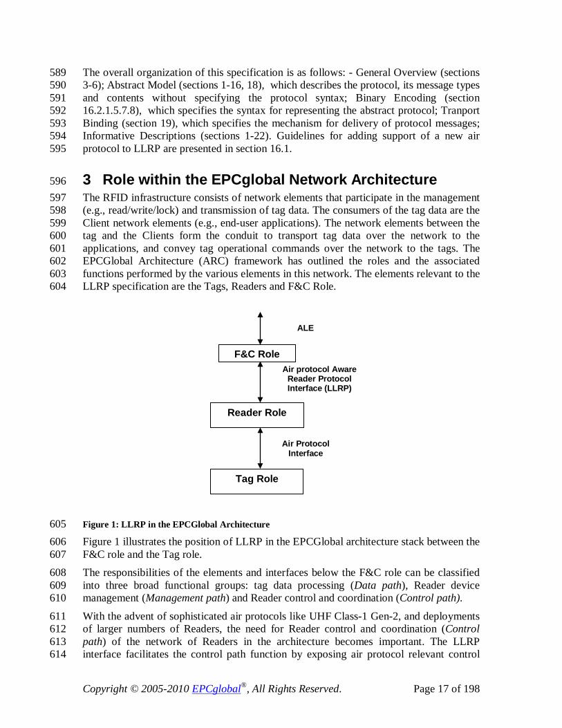
3 Role within the EPCglobal Network Architecture 596 The RFID infrastructure consists of network elements that participate in the management 597 (e.g., read/write/lock) and transmission of tag data. The consumers of the tag data are the 598 Client network elements (e.g., end-user applications). The network elements between the 599 tag and the Clients form the conduit to transport tag data over the network to the 600 applications, and convey tag operational commands over the network to the tags. The 601 EPCGlobal Architecture (ARC) framework has outlined the roles and the associated 602 functions performed by the various elements in this network. The elements relevant to the 603 LLRP specification are the Tags, Readers and F&C Role. 604
Figure 1: LLRP in the EPCGlobal Architecture 605 Figure 1 illustrates the position of LLRP in the EPCGlobal architecture stack between the 606 F&C role and the Tag role. 607 The responsibilities of the elements and interfaces below the F&C role can be classified 608 into three broad functional groups: tag data processing (Data path), Reader device 609 management (Management path) and Reader control and coordination (Control path). 610
With the advent of sophisticated air protocols like UHF Class-1 Gen-2, and deployments 611 of larger numbers of Readers, the need for Reader control and coordination (Control 612 path) of the network of Readers in the architecture becomes important. The LLRP 613 interface facilitates the control path function by exposing air protocol relevant control 614
F&C Role Air protocol Aware
Reader Protocol Interface (LLRP)
Reader Role
Tag Role
ALE
Air Protocol Interface

Copyright © 2005-2010 EPCglobal®, All Rights Reserved. Page 18 of 198
knobs to the F&C role. To that effect, LLRP is designed to be extensible in terms of 615 supporting multiple air protocols. 616
The physical and logical requirements for the communication between the Reader and the 617 tag are defined by the air protocol. Specifically, the air protocol defines the signaling 618 layer of the communication link, the Reader and tag operating procedures and commands, 619 and the collision arbitration (also known as singulation) scheme to identify a specific tag 620 in a multiple-tag environment. One such air protocol is the EPCGlobal Class-1 621 Generation 2 (C1G2) protocol. The tag memory in the C1G2 protocol is logically 622 separated into four distinct banks: reserved memory, EPC memory, TID memory and 623 user memory. The physical memory map of the tag is vendor-specific. The air protocol 624 commands that access memory have a parameter that selects the bank, and an address 625 parameter to select a particular memory location within that bank. 626
The fundamental operations a Reader performs on a tag population are inventory and 627 access. Inventory is the operation of identifying tags, and comprises multiple air protocol 628 commands. Using the singulation scheme, the Reader detects a single tag reply and 629 requests the EPC memory contents from the tag. Access is the operation of 630 communicating with (reading from and/or writing to) a tag. An individual tag must be 631 uniquely identified prior to access. Similar to the inventory operation, access comprises 632 multiple air protocol commands. In addition, a Reader can choose a subset of the tag 633 population for inventory and access. This operation is called Select in the C1G2 protocol. 634 The select operation is used to select and/or de-select a particular tag population for the 635 subsequent inventory and/or access operation. This helps focus the operations on the 636 desired subset of tags, and also thins the tag population participating in the singulation 637 operation, thereby improving the overall singulation rate. 638
It is anticipated that overall system performance may be optimized by tuning the RF, 639 singulation and air protocol parameters within and across Readers. The performance can 640 be further optimized if the tuning is done cognizant of the RF environment in the vicinity 641 of the Reader. 642
The LLRP interface between the Client and the Reader facilitates the management of 643 Reader devices to mitigate Reader-to-tag and Reader-to-Reader interference and 644 maximize the efficiency of singulation and data operations over the tag population. This 645 is achieved by enabling the Reader device operation at the full performance level of the 646 air protocol. In addition, LLRP provides the interface to transport the results of RF 647 monitoring (a.k.a RF survey) if the Reader device is capable of performing that function. 648
In addition, there will be a number of applications that perform operations on the RFID 649 tag data. Operations may range from reading EPC IDs to performing other tag access 650 operations exposed by the air protocol like read, write, kill, lock, etc. Multiple application 651 requirements translate into a set of access operations that a Reader or a set of Readers 652 perform on tags as and when they are in the field of view. The LLRP interface provides a 653 scalable mechanism to manage the access operations at the Reader devices. 654
Lastly, scalable device management capabilities are critical for operations of a large 655 network of Reader devices. The LLRP interface facilitates device status and error 656 reporting, and device capabilities discovery. 657

Copyright © 2005-2010 EPCglobal®, All Rights Reserved. Page 19 of 198
4 Terminology and Typographical Conventions 658 Within this specification, the terms SHALL, SHALL NOT, SHOULD, SHOULD NOT, 659 MAY, NEED NOT, CAN, and CANNOT are to be interpreted as specified in Annex G of 660 the ISO/IEC Directives, Part 2, 2001, 4th edition [ISODir2]. When used in this way, 661 these terms will always be shown in ALL CAPS; when these words appear in ordinary 662 typeface they are intended to have their ordinary English meaning. However in this 663 document only a subset of the terms listed above SHALL be used. The subset of 664 acceptable terms includes the following: SHALL, SHALL NOT and MAY. The terms 665 SHOULD, SHOULD NOT, NEED NOT, CAN, and CANNOT, SHALL NOT be used. 666 All sections of this document, with the exception of section 1-3, 1-22, are normative, 667 except where explicitly noted as non-normative. All figures within the document are non-668 normative unless otherwise specified. 669
The following typographical conventions are used throughout the document: 670 ALL CAPS type is used for the special terms from [ISODir2] enumerated above. 671
ALL_CAPS_UNDERSCORE type is used for LLRP message names. 672 CamelBackType is used for LLRP parameter and data field names. 673
Monospace type is used to denote programming language, UML, and XML identifiers, 674 as well as for the text of XML documents. 675
5 Overview of LLRP 676 LLRP is specifically concerned with providing the formats and procedures of 677 communications between a Client and a Reader. The LLRP protocol data units are called 678 messages. Messages from the Client to the Reader include getting and setting 679 configuration of Readers, capabilities discovery of Readers and managing the inventory 680 and access operations at the Readers. Messages from the Reader to the Client include the 681 reporting of Reader status, RF survey, and inventory and access results. 682
LLRP is an application layer protocol and does not provide retransmission, or reordering 683 facilities. State consistency between the Client and the Reader is critical for the correct 684 functioning of the system. Using LLRP messages, the Client updates the Reader state 685 which includes Reader configuration parameters, dynamically created data structures 686 (e.g., ROSpecs, AccessSpecs, etc), and possibly vendor defined data. For this reason, 687 LLRP requires acknowledgements for the Client to Reader transactions – this provides a 688 fail-safe mechanism at the LLRP layer to cope with network error situations. Also, to 689 cope with intermittent connections, a Client can request a Reader's configuration state to 690 confirm that a Reader's state is consistent with the Client after the Client reconnects (see 691 LLRPConfigurationStateValue in section 13.2.1). The Reader to Client messages are 692 primarily reports, status notifications or keepalives. Only the keepalives are 693 acknowledged by the Client. 694 695

Copyright © 2005-2010 EPCglobal®, All Rights Reserved. Page 20 of 198
696 Figure 2: LLRP Endpoints 697 As shown in Figure 2, from LLRP’s perspective, a Reader contains a collection of one or 698 more antennas. Moreover, Readers as used in this specification may not necessarily be in 699 one-to-one correspondence with hardware devices. 700
5.1 Typical LLRP Timeline 701 The typical timeline of a LLRP connection has two phases: version negotiation, and 702 runtime. 703
5.1.1 Version Negotiation 704 There are multiple documented versions of LLRP, and a Client and a Reader must 705 negotiate a mutually supported protocol version for each connection. When a LLRP 706 connection is first established, both Client and Reader assume LLRP version 1. With the 707 exception of the version negotiation messages themselves, only version 1 messages are 708 sent by the Client and Reader until the version negotiation process is complete. Version 709 negotiation is performed using version 2 messages and is initiated by the Client. The 710 Client requests the supported protocol version from the Reader, determines an 711 appropriate version for the connection, and instructs the reader as to the protocol to use. 712 Once a version has been established using this procedure, all subsequent messages are 713 sent using the negotiated protocol version. The details of this procedure can be found in 714 section 9, with detailed message sequence charts found in section 20.1.3. 715 A typical version negotiation timeline between a Client and a Reader is depicted in 716 Figure 3. 717
Reader
Antenna
Client
Reader . . . LLRP

Copyright © 2005-2010 EPCglobal®, All Rights Reserved. Page 21 of 198
Client Reader
Connection Successful (ver 1)
Get Supported Versions (ver 2)
Get Supported Versions Response (ver 2)
Set Protocol Version (ver 2)
Set Protocol Version Response (ver 2)
Runtime Messages (ver x)
Client discovers what protocolversions the Reader supports
Client selects an appropriateprotocol version and instructsthe Reader to set version x
LLRP runtime messages areexchanged using the negotiatedprotocol version
718 Figure 3: Typical LLRP Version Negotiation Timeline 719
5.1.2 Runtime Operation 720 LLRP runtime operation consists of the following phases of execution: 721
• Capability discovery 722
• Device configuration 723
• [optional] Inventory and access operations setup 724
• Inventory cycles executed 725 If tag conditions matched, access operations will be executed during inventory 726 cycle execution. Access operations include reading, writing, and locking tag 727 memory, killing tags, etc. 728
• RF Survey operations executed 729
• Reports returned to the Client 730 A typical timeline of both LLRP and air protocol interactions between a Client, a Reader 731 and a population of tags is depicted in Figure 4. 732
733
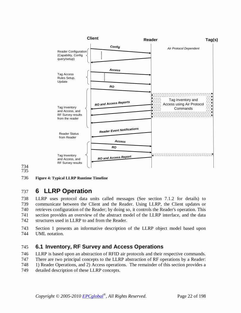
Copyright © 2005-2010 EPCglobal®, All Rights Reserved. Page 22 of 198
Client Reader Tag(s)
Reader Configuration(Capability, Config query/setup)
Tag Access Rules Setup, Update
RO
Access
Air Protocol Dependent
Tag inventory andAccess using Air Protocol
Commands
RO and Access Report
Tag Inventory and Access, and RF Survey results from the reader
Access
RO and Access Reports
RO
Config
Reader Event Notifications
Tag Inventory and Access, and RF Survey results
Reader Statusfrom Reader
734 735 Figure 4: Typical LLRP Runtime Timeline 736
6 LLRP Operation 737 LLRP uses protocol data units called messages (See section 7.1.2 for details) to 738 communicate between the Client and the Reader. Using LLRP, the Client updates or 739 retrieves configuration of the Reader; by doing so, it controls the Reader's operation. This 740 section provides an overview of the abstract model of the LLRP interface, and the data 741 structures used in LLRP to and from the Reader. 742
Section 1 presents an informative description of the LLRP object model based upon 743 UML notation. 744
6.1 Inventory, RF Survey and Access Operations 745 LLRP is based upon an abstraction of RFID air protocols and their respective commands. 746 There are two principal concepts to the LLRP abstraction of RF operations by a Reader: 747 1) Reader Operations, and 2) Access operations. The remainder of this section provides a 748 detailed description of these LLRP concepts. 749
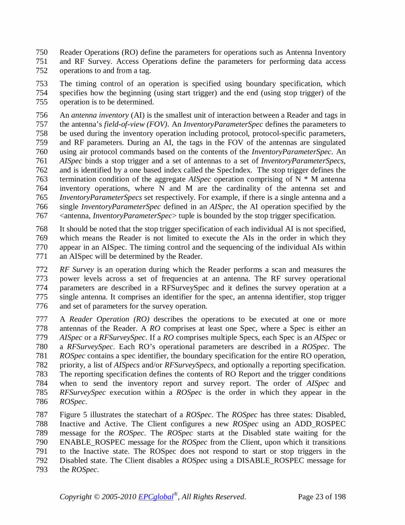
Copyright © 2005-2010 EPCglobal®, All Rights Reserved. Page 23 of 198
Reader Operations (RO) define the parameters for operations such as Antenna Inventory 750 and RF Survey. Access Operations define the parameters for performing data access 751 operations to and from a tag. 752 The timing control of an operation is specified using boundary specification, which 753 specifies how the beginning (using start trigger) and the end (using stop trigger) of the 754 operation is to be determined. 755
An antenna inventory (AI) is the smallest unit of interaction between a Reader and tags in 756 the antenna’s field-of-view (FOV). An InventoryParameterSpec defines the parameters to 757 be used during the inventory operation including protocol, protocol-specific parameters, 758 and RF parameters. During an AI, the tags in the FOV of the antennas are singulated 759 using air protocol commands based on the contents of the InventoryParameterSpec. An 760 AISpec binds a stop trigger and a set of antennas to a set of InventoryParameterSpecs, 761 and is identified by a one based index called the SpecIndex. The stop trigger defines the 762 termination condition of the aggregate AISpec operation comprising of N * M antenna 763 inventory operations, where N and M are the cardinality of the antenna set and 764 InventoryParameterSpecs set respectively. For example, if there is a single antenna and a 765 single InventoryParameterSpec defined in an AISpec, the AI operation specified by the 766 <antenna, InventoryParameterSpec> tuple is bounded by the stop trigger specification. 767
It should be noted that the stop trigger specification of each individual AI is not specified, 768 which means the Reader is not limited to execute the AIs in the order in which they 769 appear in an AISpec. The timing control and the sequencing of the individual AIs within 770 an AISpec will be determined by the Reader. 771
RF Survey is an operation during which the Reader performs a scan and measures the 772 power levels across a set of frequencies at an antenna. The RF survey operational 773 parameters are described in a RFSurveySpec and it defines the survey operation at a 774 single antenna. It comprises an identifier for the spec, an antenna identifier, stop trigger 775 and set of parameters for the survey operation. 776 A Reader Operation (RO) describes the operations to be executed at one or more 777 antennas of the Reader. A RO comprises at least one Spec, where a Spec is either an 778 AISpec or a RFSurveySpec. If a RO comprises multiple Specs, each Spec is an AISpec or 779 a RFSurveySpec. Each RO’s operational parameters are described in a ROSpec. The 780 ROSpec contains a spec identifier, the boundary specification for the entire RO operation, 781 priority, a list of AISpecs and/or RFSurveySpecs, and optionally a reporting specification. 782 The reporting specification defines the contents of RO Report and the trigger conditions 783 when to send the inventory report and survey report. The order of AISpec and 784 RFSurveySpec execution within a ROSpec is the order in which they appear in the 785 ROSpec. 786 Figure 5 illustrates the statechart of a ROSpec. The ROSpec has three states: Disabled, 787 Inactive and Active. The Client configures a new ROSpec using an ADD_ROSPEC 788 message for the ROSpec. The ROSpec starts at the Disabled state waiting for the 789 ENABLE_ROSPEC message for the ROSpec from the Client, upon which it transitions 790 to the Inactive state. The ROSpec does not respond to start or stop triggers in the 791 Disabled state. The Client disables a ROSpec using a DISABLE_ROSPEC message for 792 the ROSpec. 793
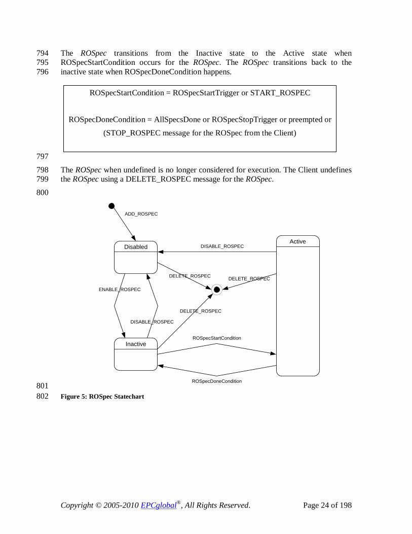
Copyright © 2005-2010 EPCglobal®, All Rights Reserved. Page 24 of 198
The ROSpec transitions from the Inactive state to the Active state when 794 ROSpecStartCondition occurs for the ROSpec. The ROSpec transitions back to the 795 inactive state when ROSpecDoneCondition happens. 796
797
The ROSpec when undefined is no longer considered for execution. The Client undefines 798 the ROSpec using a DELETE_ROSPEC message for the ROSpec. 799
800
ADD_ROSPEC
ENABLE_ROSPEC
DISABLE_ROSPEC
Inactive
Disabled
DELETE_ROSPEC
DELETE_ROSPEC DELETE_ROSPEC
DISABLE_ROSPEC
ROSpecStartCondition
ROSpecDoneCondition
Active
801 Figure 5: ROSpec Statechart 802
ROSpecStartCondition = ROSpecStartTrigger or START_ROSPEC
ROSpecDoneCondition = AllSpecsDone or ROSpecStopTrigger or preempted or
(STOP_ROSPEC message for the ROSpec from the Client)

Copyright © 2005-2010 EPCglobal®, All Rights Reserved. Page 25 of 198
Active
SpecIndex = 1
Move the SpecIndexSpec to the Active State
SpecIndexSpec Type
AISpecStopTrigger?
RFSurveySpecStopTrigger?
RemainingSpecs?
SpecIndex =SpecIndex + 1
AISpec RFSurveySpec
Yes Yes
NoYes
Execute AISpec Execute RFSurveySpec
No No
Move the SpecIndexSpec to the Inactive
State
SpecIndexSpec TypeLoopSpec?
LoopCount > 0
All Specs Done
LoopCount =LoopCount - 1
Yes
No
Yes
No
803 Figure 6: ROSpec Active State 804 LLRP supports configuring multiple ROSpecs. Each ROSpec has a priority field. The 805 default is for all the ROSpecs to have the same priority. Since the start trigger for the 806 ROSpec can be an asynchronous event, there may be situations where a ROSpec’s start 807 trigger event occurs when the Reader is busy executing another ROSpec. The Client, 808 when setting up a ROSpec, can set the appropriate priority so that a high priority ROSpec 809 can preempt a currently active lower priority ROSpec and start execution as soon as the 810 ROSpecStartCondition for the higher priority, inactive ROSpec occurs. The ROSpec that 811 got preempted transitions to the Inactive state. 812
Figure 7 illustrates the AISpec statechart. When the parent ROSpec moves to the active 813 state, each AISpec in the ROSpec starts at the inactive state. During an active ROSpec’s 814
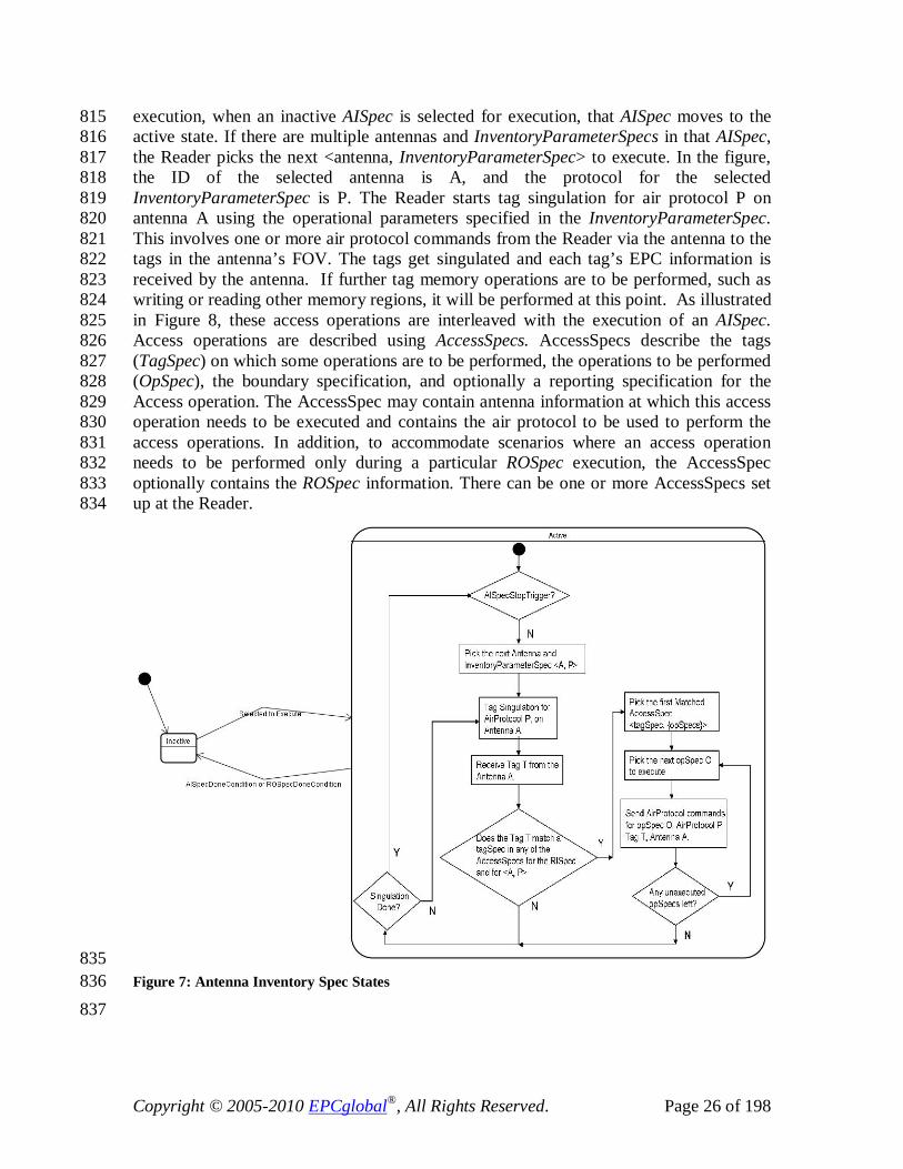
Copyright © 2005-2010 EPCglobal®, All Rights Reserved. Page 26 of 198
execution, when an inactive AISpec is selected for execution, that AISpec moves to the 815 active state. If there are multiple antennas and InventoryParameterSpecs in that AISpec, 816 the Reader picks the next <antenna, InventoryParameterSpec> to execute. In the figure, 817 the ID of the selected antenna is A, and the protocol for the selected 818 InventoryParameterSpec is P. The Reader starts tag singulation for air protocol P on 819 antenna A using the operational parameters specified in the InventoryParameterSpec. 820 This involves one or more air protocol commands from the Reader via the antenna to the 821 tags in the antenna’s FOV. The tags get singulated and each tag’s EPC information is 822 received by the antenna. If further tag memory operations are to be performed, such as 823 writing or reading other memory regions, it will be performed at this point. As illustrated 824 in Figure 8, these access operations are interleaved with the execution of an AISpec. 825 Access operations are described using AccessSpecs. AccessSpecs describe the tags 826 (TagSpec) on which some operations are to be performed, the operations to be performed 827 (OpSpec), the boundary specification, and optionally a reporting specification for the 828 Access operation. The AccessSpec may contain antenna information at which this access 829 operation needs to be executed and contains the air protocol to be used to perform the 830 access operations. In addition, to accommodate scenarios where an access operation 831 needs to be performed only during a particular ROSpec execution, the AccessSpec 832 optionally contains the ROSpec information. There can be one or more AccessSpecs set 833 up at the Reader. 834
835 Figure 7: Antenna Inventory Spec States 836 837

Copyright © 2005-2010 EPCglobal®, All Rights Reserved. Page 27 of 198
838 Figure 8: Access Operations Interleaved in an Antenna Inventory Operation 839 In Figure 7, when tags are received as a result of singulation, a check is performed to 840 determine if the received tag matches the TagSpec defined in any of the Active (See 841 statechart in Figure 10) AccessSpecs. In case there are multiple AccessSpecs that get 842 matched during a tagSpec lookup, the Reader will execute the first AccessSpec that 843 matches, where the ordering of the AccessSpecs is the order in which the AccessSpecs 844 were created by the Client. 845 When an AccessSpec is executed, the set of operations as specified in OpSpecs of the 846 AccessSpec are performed on the tag, which results in one or more air protocol 847 commands and responses transacted between the Reader and the tag via antenna A over 848 air protocol P. In order to support cases where the Reader needs to query the Client for 849 further information to complete the operation on the tag, there is an OpSpec called the 850 ClientRequestOpSpec. 851
Antenna Inventory
Acc
ess O
pera
tions
Acc
ess O
pera
tions
Acc
ess O
pera
tions
Acc
ess O
pera
tions
Acc
ess O
pera
tions
time

Copyright © 2005-2010 EPCglobal®, All Rights Reserved. Page 28 of 198
OpSpec2 = ClientRequestOpSpec
OpSpec1 = Tag Operation
Client Reader Tag
CLIENT_REQUEST_OP
CLIENT_REQUEST_OP_RESPONSE
OpSpec3 = Tag Operation
OpSpec2 = ClientRequestOpSpec
OpSpec1 = Tag Operation
Client Reader Tag
CLIENT_REQUEST_OP
CLIENT_REQUEST_OP_RESPONSE
OpSpec3 = Tag Operation
852 Figure 9: Client Request OpSpec 853 Figure 9 illustrates the message interaction between the Client, Reader and Tag for a 854 ClientRequestOpSpec. For OpSpecs that are not ClientRequestOpSpec, the Reader 855 performs the operations on the tag using the the air protocol commands. If an OpSpec is 856 of the ClientRequestOpSpec, the Reader sends the result of the ongoing AccessSpec till 857 that point in a CLIENT_REQUEST_OP message, so that the Client has all the relevant 858 information to send a response. The client response is carried in a 859 CLIENT_REQUEST_OP_RESPONSE message. This message is the set of OpSpecs that 860 the reader should execute. The reader continues to execute the OpSpecs within an 861 AccessSpec until all opSpecs have been executed or until an error occurs. When 862 execution completes, the reader resumes the inventory operation. 863 The AISpec transitions back to the inactive state when AISpecDoneCondition occurs or 864 when the parent ROSpec’s ROSpecDoneCondition occurs. 865 866
867 868
AISpecDoneCondition = AISpecStopTrigger

Copyright © 2005-2010 EPCglobal®, All Rights Reserved. Page 29 of 198
869 Figure 10: Access Spec States 870 Figure 10 illustrates the AccessSpec’s states. The Client configures an AccessSpec using 871 an ADD_ACCESS_SPEC message for the AccessSpec. The AccessSpec starts at the 872 Disabled state, waiting for an ENABLE_ACCESS_SPEC message from the Client for 873 that AccessSpec, upon which it enters the Active state. It is only in the Active state that 874 the AccessSpec is considered for execution. The Client can disable an AccessSpec using a 875 DISABLE_ACCESS_SPEC message for the AccessSpec. The AccessSpec when 876 undefined is no longer considered for execution. The Client undefines the AccessSpec 877 using a DELETE_ACCESS_SPEC message for the AccessSpec. 878 In order for the Reader to take a local action to limit the validity of an AccessSpec, the 879 Client can configure a stop trigger for the AccessSpec. An example use case of the stop 880 trigger is when an AccessSpec is defined on all the antennas, and the desired behavior is 881 to operate on the tag only once, the first time it is seen at any antenna. When the 882 AccessStopCondition occurs, the AccessSpec transitions to undefined and is no longer 883 considered for execution. 884 885
886 887
Figure 11 illustrates the RFSurveySpec statechart. When the parent ROSpec moves to the 888 active state, each RFSurveySpec in the ROSpec starts at the inactive state. During an 889 active ROSpec’s execution, when an inactive RFSurveySpec is selected for execution, 890 that RFSurveySpec moves to the active state. In the active state, the Reader executes the 891 survey operation as specified by the RFSurveySpec. The RFSurveySpec transitions back 892 to the inactive state when the RFSurveySpecDoneCondition occurs or when the parent 893 ROSpec’s ROSpecDoneCondition occurs. 894 895
896
AccessStopCondition = AccessSpecStopTrigger
RFSurveyStopCondition = RFSurveySpecStopTrigger
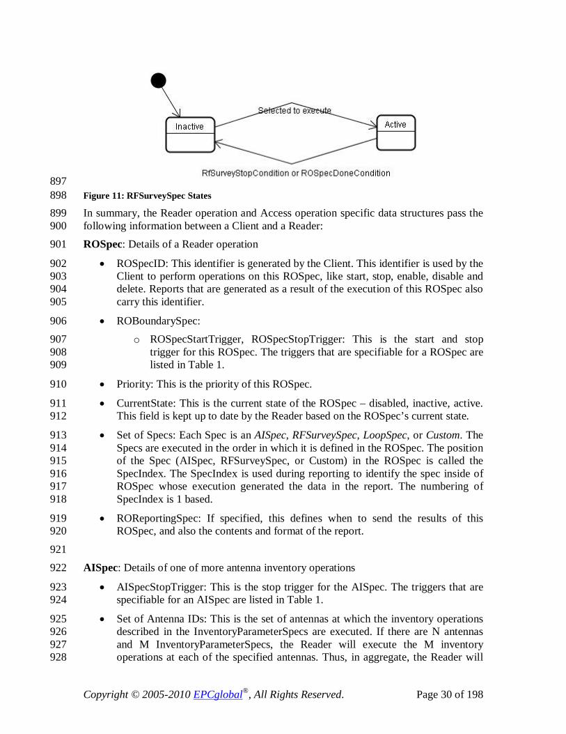
Copyright © 2005-2010 EPCglobal®, All Rights Reserved. Page 30 of 198
897 Figure 11: RFSurveySpec States 898 In summary, the Reader operation and Access operation specific data structures pass the 899 following information between a Client and a Reader: 900 ROSpec: Details of a Reader operation 901
• ROSpecID: This identifier is generated by the Client. This identifier is used by the 902 Client to perform operations on this ROSpec, like start, stop, enable, disable and 903 delete. Reports that are generated as a result of the execution of this ROSpec also 904 carry this identifier. 905
• ROBoundarySpec: 906 o ROSpecStartTrigger, ROSpecStopTrigger: This is the start and stop 907
trigger for this ROSpec. The triggers that are specifiable for a ROSpec are 908 listed in Table 1. 909
• Priority: This is the priority of this ROSpec. 910
• CurrentState: This is the current state of the ROSpec – disabled, inactive, active. 911 This field is kept up to date by the Reader based on the ROSpec’s current state. 912
• Set of Specs: Each Spec is an AISpec, RFSurveySpec, LoopSpec, or Custom. The 913 Specs are executed in the order in which it is defined in the ROSpec. The position 914 of the Spec (AISpec, RFSurveySpec, or Custom) in the ROSpec is called the 915 SpecIndex. The SpecIndex is used during reporting to identify the spec inside of 916 ROSpec whose execution generated the data in the report. The numbering of 917 SpecIndex is 1 based. 918
• ROReportingSpec: If specified, this defines when to send the results of this 919 ROSpec, and also the contents and format of the report. 920
921 AISpec: Details of one of more antenna inventory operations 922
• AISpecStopTrigger: This is the stop trigger for the AISpec. The triggers that are 923 specifiable for an AISpec are listed in Table 1. 924
• Set of Antenna IDs: This is the set of antennas at which the inventory operations 925 described in the InventoryParameterSpecs are executed. If there are N antennas 926 and M InventoryParameterSpecs, the Reader will execute the M inventory 927 operations at each of the specified antennas. Thus, in aggregate, the Reader will 928

Copyright © 2005-2010 EPCglobal®, All Rights Reserved. Page 31 of 198
execute N * M AIs (Antenna inventory operations). The ordering of the AIs is 929 determined by the Reader. 930
• Set of InventoryParameterSpecs: There can be one or more 931 InventoryParameterSpecs specified as part of the AISpec. Collectively, they are 932 bound by the AISpecStopTrigger. The order in which the antenna inventory 933 operations described as <Antenna, InventoryParameterSpec> are executed is 934 determined in a proprietary manner inside the Reader. 935
936
InventoryParameterSpec: Operational parameters for an inventory using a single air 937 protocol. 938
• InventoryParameterSpecID: This identifier is generated by the Client. Reports that 939 are generated as a result of the execution of this InventoryParameterSpec carry 940 this identifier. 941
• Air Protocol: This is the air protocol that is used to inventory the tags in the field 942 of view of the antenna. 943
• Set of Antenna Configuration Settings: Each Antenna Configuration setting 944 comprises of 945
o Antenna ID: The identifier of the antenna 946 o RFTransmitterSettings: This describes the configuration of the transmitter 947
during the inventory operation. 948 o RFReceiverSettings: This describes the configuration of the receiver 949
during the inventory operation. 950 o AirProtocolInventoryCommandSettings parameters: This describes the 951
configuration of the air protocol parameters for the inventory operation. 952 953
RFSurveySpec: Details of a RF Survey operation 954
• RFSurveySpecID: This identifier is generated by the Client. Reports that are 955 generated as a result of the survey operation carry this identifier. 956
• RFSurveySpecStopTrigger: This is the stop trigger for the RFSurveySpec. The 957 triggers that are specifiable for a RFSurveySpec are listed in Table 1. 958
• AntennaID: This is the antenna at which the survey operation is to be executed. 959
• StartFrequency: This is the starting channel for which power levels need to be 960 measured during this RF survey operation. 961
• EndFrequency: This is the ending channel for which power levels need to be 962 measured during this RF survey operation. The RF survey operation is performed 963 on frequency channels between the specified Start Frequency and End frequency. 964
965
LoopSpec: Instructs the Reader to execute the first Spec in the Set of Specs. 966

Copyright © 2005-2010 EPCglobal®, All Rights Reserved. Page 32 of 198
• LoopCount: This value instructs the reader on the number of times to loop 967 through the Set of Specs within the ROSpec. 968
969 AccessSpec: Details of an access operation. 970
• AccessSpecID: This identifier is generated by the Client upon creation of this 971 AccessSpec. This identifier is used by the Client to perform operations on this 972 AccessSpec, like start, stop and delete. Reports that are generated as a result of 973 the execution of this AccessSpec also carry this identifier. 974
• AntennaID: This is the identifier of the antenna for whose tag observations this 975 AccessSpec is executed. 976
• Air Protocol: This is the air protocol used to perform access operations on the tag. 977
• ROSpecID: This is the identifier of the ROSpec during whose tag observations 978 this AccessSpec is executed. 979
• CurrentState: This is the current state of the AccessSpec – disabled, active. This 980 field is kept up to date by the Reader based on the AccessSpec’s current state. 981
• AccessSpecStopTrigger: If specified, this is the trigger to undefine the 982 AccessSpec upon the occurrence of the stop trigger. 983
• AccessCommand: This parameter is used to configure the air protocol parameters 984 for the access operation. At a minimum, this specifies the tag filters for which the 985 access operations are to be performed, and the list of operations to be performed 986 on the tag. 987
o TagSpec: This describes the tag filters and is specified in terms of the air 988 protocol’s tag memory layout. 989
o List of OpSpecs: This is specified in terms of the air protocol’s tag access 990 operations. The order of execution is determined by the order in which it is 991 configured in the AccessSpec. 992
• AccessReportSpec: If specified, this defines when to send the results of this 993 AccessSpec, and also the contents and format of the report. 994
6.1.1 Operation Triggers 995 This section describes the triggers that can be configured using LLRP to control the 996 various operations. 997
6.1.1.1 Summary 998 The specific triggers used to control the various operations are presented in a tabular 999 fashion. 1000
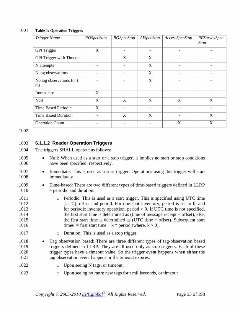
Copyright © 2005-2010 EPCglobal®, All Rights Reserved. Page 33 of 198
Table 1: Operation Triggers 1001 Trigger Name ROSpecStart ROSpecStop AISpecStop AccessSpecStop RFSurveySpec
Stop
GPI Trigger X - - - -
GPI Trigger with Timeout - X X - -
N attempts - - X - -
N tag observations - - X - -
No tag observations for t ms
- - X - -
Immediate X - - - -
Null X X X X X
Time Based Periodic X - - - -
Time Based Duration - X X - X
Operation Count - - - X X
1002
6.1.1.2 Reader Operation Triggers 1003 The triggers SHALL operate as follows: 1004
• Null: When used as a start or a stop trigger, it implies no start or stop conditions 1005 have been specified, respectively. 1006
• Immediate: This is used as a start trigger. Operations using this trigger will start 1007 immediately. 1008
• Time-based: There are two different types of time-based triggers defined in LLRP 1009 – periodic and duration. 1010
o Periodic: This is used as a start trigger. This is specified using UTC time 1011 [UTC], offset and period. For one-shot inventory, period is set to 0, and 1012 for periodic inventory operation, period > 0. If UTC time is not specified, 1013 the first start time is determined as (time of message receipt + offset), else, 1014 the first start time is determined as (UTC time + offset). Subsequent start 1015 times = first start time + k * period (where, k > 0). 1016
o Duration: This is used as a stop trigger. 1017
• Tag observation based: There are three different types of tag-observation based 1018 triggers defined in LLRP. They are all used only as stop triggers. Each of these 1019 trigger types have a timeout value. So the trigger event happens when either the 1020 tag observation event happens or the timeout expires. 1021
o Upon seeing N tags, or timeout. 1022 o Upon seeing no more new tags for t milliseconds, or timeout 1023

Copyright © 2005-2010 EPCglobal®, All Rights Reserved. Page 34 of 198
o N attempts to see all the tags in the field of view, or timeout 1024
• External events: These are due to events received at Reader interfaces like signal 1025 transition on a GPI port or a message on the network port. 1026
o GPI event at a GPI port, or a timeout 1027
o Client triggers: A Client can instruct the Reader to start/stop a particular 1028 operation using LLRP messages. 1029
• Operation count: This is used as a stop trigger for RFSurvey. This trigger limits 1030 the number of times the Reader takes survey measurements across the specified 1031 frequency range. 1032
AI and RFSurvey specs do not contain start triggers. The first spec (AISpec or 1033 RFSurveySpec) starts when the ROSpec enters the active state. The kth Spec in the 1034 ROSpec starts immediately after the completion of the k-1th Spec. 1035 When Null is specified as a stop trigger for a Spec ((either AISpec or RFSurveySpec), the 1036 execution of the Spec is stopped only when the parent ROSpec’s ROSpecDoneCondition 1037 occurs. 1038
6.1.1.3 Access Operation Triggers 1039 AccessSpecs do not contain start triggers. An AccessSpec when enabled using 1040 ENABLE_ACCESS_SPEC will transition to the active state. There is only one type of 1041 stop trigger for controlling the validity of an AccessSpec: 1042
• Operation count: This is used as a stop trigger. This trigger is useful to limit the 1043 number of times the instance of the operation is executed during its lifetime. 1044
6.2 Reporting, Event Notification and Keepalives 1045 The results of the inventory, access and RF survey operations, will be sent by the Reader 1046 to the Client in the form of reports. Using LLRP, the Client is capable of setting up the 1047 triggers that determine when the report is to be sent by the Reader, and also the contents 1048 and format of the report. The report message is RO_ACCESS_REPORT. The triggers 1049 and report contents can be configured in one of the following ways: 1050
• Differently for each ROSpec and AccessSpec when creating them using the 1051 ADD_ROSPEC and ADD_ACCESSSPEC messages, respectively. 1052
• Global default using the SET_READER_CONFIG message. 1053 Table 2 summarizes the triggers available in LLRP to control when the RO report and the 1054 AccessReport is to be generated and sent by the Reader. 1055 Table 2: Reporting Triggers 1056 Trigger Name ROReport AccessReport
None X -

Copyright © 2005-2010 EPCglobal®, All Rights Reserved. Page 35 of 198
(Upon N tags or End of Spec), where Spec = AISpec or RFSurveySpec
X -
Upon N tags or End of ROSpec
X -
(Upon N seconds or milliseconds or End of Spec), where Spec = AISpec or RFSurveySpec
X
Upon N seconds or milliseconds or End of ROSpec
X
End of AccessSpec execution
- X
Whenever ROReport is generated for the RO that triggered the execution of this AccessSpec
- X
1057
In addition to data reports, the Client can configure the Reader to enable or disable 1058 notification of events as and when it happens at the Reader. Some examples of events are 1059 frequency hop, buffer overflow, etc. 1060 In order to monitor the LLRP-layer connectivity with the Reader, the Client can 1061 configure the Reader to send Keepalives periodically. The Keepalive message is 1062 acknowledged by the Client, using which, the Reader can also monitor the LLRP-layer 1063 connectivity with a Client. The Keepalives can be disabled. If enabled, the periodicity of 1064 the message is specified by the Client. 1065

Copyright © 2005-2010 EPCglobal®, All Rights Reserved. Page 36 of 198
7 Messages, Parameters and Fields 1066 LLRP is a message-oriented protocol made up of data elements called protocol data units. 1067 This section provides the details of each message type and parameter type, and expresses 1068 them in an abstract manner. The section starts with an overview of the message types and 1069 parameters, where the messages are grouped into separate functional groups. 1070
7.1 Overview 1071 LLRP provides an extensible mechanism to support existing and new air protocols. It is 1072 achieved by decoupling messages from parameters – using a common message structure 1073 across air protocols, and providing extensibility in the form of parameters. 1074
7.1.1 Formatting Conventions and Data Types 1075 LLRP messages and parameters are defined using the graphical notation below. 1076
1077 Figure 12: Box Formats for Messages and Parameters 1078 1079 Contained within the box is an ordered list of sub-parameters and fields contained within 1080 the message or parameter. The field/parameter names are shown in boldface, followed 1081 by the data type and a brief description of the field/parameter when necessary. Fields 1082 with values that are restricted to a subset of the range of their data type have their 1083 possible and legal values shown in italics below the field name. 1084
1085 Fields are composed of one of the following basic data types: 1086
Bit – An integer with only two possible values, 0 or 1 1087 Bit Array – A sequence of bits. 1088
Byte Array – A sequence of bytes. 1089 Boolean – A field that can take the values TRUE or FALSE. 1090
The contents of a LLRP message are listed within a box with a double line border such as this.
The contents of a LLRP message parameter are listed with a box with a single line border such as this.

Copyright © 2005-2010 EPCglobal®, All Rights Reserved. Page 37 of 198
Integer – An integer can take any whole number. When this value is used in the abstract 1091 specification, the Possible Values element will specify the possible and legal value for a 1092 particular field. 1093 Short Array – A sequence of unsigned short integers 1094
Signed Integer – A signed integer can take any whole number value between -231 through 1095 231-1 inclusive. Within the abstract specification, the Possible Values element will 1096 enumerate any restrictions beyond these limits for a particular field. 1097 Signed Short Integer – A signed short integer can take any whole number value between 1098 -215 through 215-1 inclusive. Within the abstract specification, the Possible Values 1099 element will enumerate any restrictions beyond these limits for a particular field 1100
Unsigned Integer – An unsigned integer is a value that is between 0 through 232-1 1101 inclusive. Within the abstract specification, the Possible Values element will enumerate 1102 any restrictions beyond these limits for a particular field. 1103 Unsigned Long Integer – An unsigned long integer is a value that is between 0 through 1104 264-1 inclusive. Within the abstract specification, the Possible Values element will 1105 enumerate any restrictions beyond these limits for a particular field. 1106
Unsigned Short Integer – An unsigned short integer is a value that is between 0 through 1107 216-1 inclusive. Within the abstract specification, the Possible Values element will 1108 enumerate any restrictions beyond these limits for a particular field. 1109 UTF-8 String – A sequence of UTF-8 [UTF8] encoded characters. 1110
In addition to the basic types, fields can be defined as ‘lists’ of a basic type. A list is an 1111 ordered set of a basic type. The order is preserved by all bindings. 1112
7.1.2 Messages 1113 Each Message contains: 1114
• Version value that indicates the version of the protocol for this message. Table 3 1115 shows how the value in the version field maps to the LLRP protocol version. 1116
1117 Table 3: Version Field to Protocol Version Mapping 1118
Version Field Protocol Spec Version
1 LLRP v1.0.1
2 LLRP v1.1 1119
• Message Type value that uniquely identifies it within a protocol message. 1120
• Message ID: The Reader behavior SHALL be based upon starting the processing 1121 of messages in the order received over LLRP, however, the completion of 1122 execution of the message processing MAY not necessarily be in the same order 1123 inside the Reader. Hence, the Reader responses to the messages may be in a 1124 different order than the order of the Client messages. The Message ID is to 1125
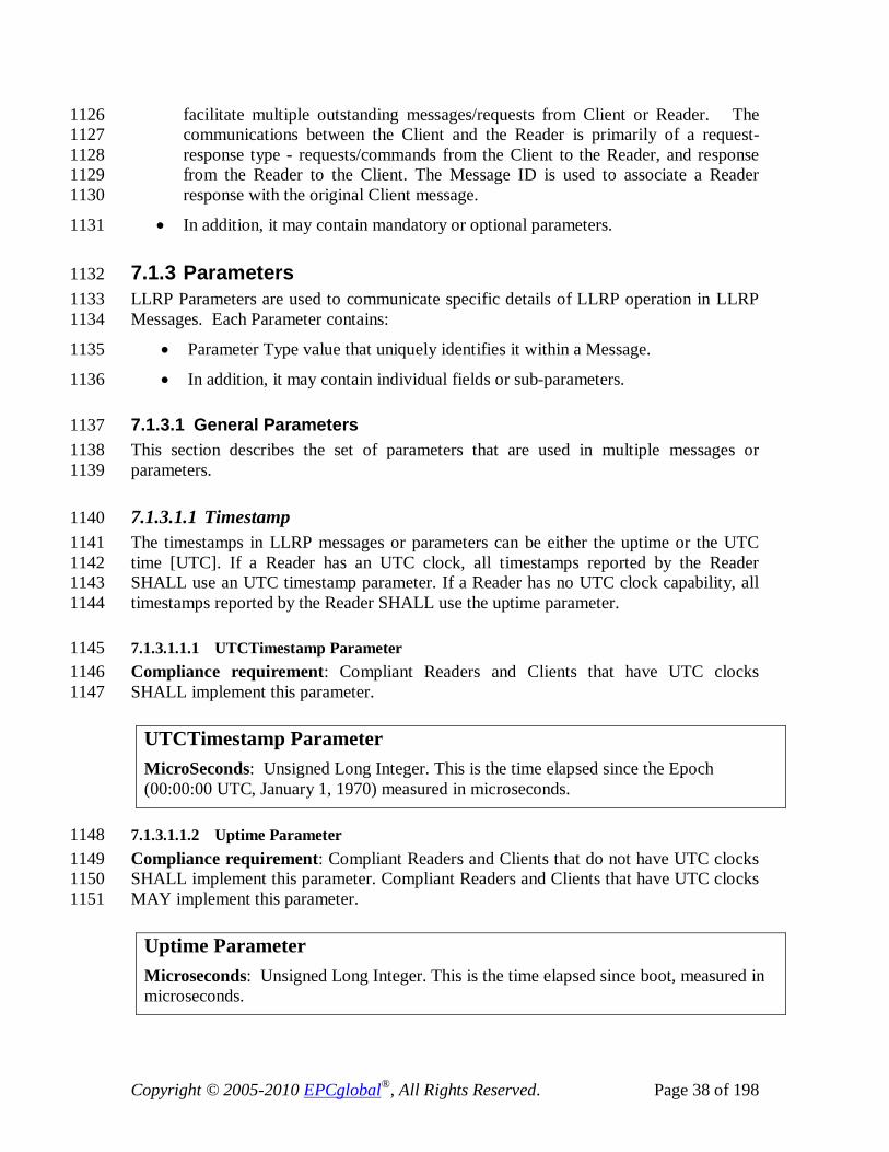
Copyright © 2005-2010 EPCglobal®, All Rights Reserved. Page 38 of 198
facilitate multiple outstanding messages/requests from Client or Reader. The 1126 communications between the Client and the Reader is primarily of a request-1127 response type - requests/commands from the Client to the Reader, and response 1128 from the Reader to the Client. The Message ID is used to associate a Reader 1129 response with the original Client message. 1130
• In addition, it may contain mandatory or optional parameters. 1131
7.1.3 Parameters 1132 LLRP Parameters are used to communicate specific details of LLRP operation in LLRP 1133 Messages. Each Parameter contains: 1134
• Parameter Type value that uniquely identifies it within a Message. 1135
• In addition, it may contain individual fields or sub-parameters. 1136
7.1.3.1 General Parameters 1137 This section describes the set of parameters that are used in multiple messages or 1138 parameters. 1139
7.1.3.1.1 Timestamp 1140 The timestamps in LLRP messages or parameters can be either the uptime or the UTC 1141 time [UTC]. If a Reader has an UTC clock, all timestamps reported by the Reader 1142 SHALL use an UTC timestamp parameter. If a Reader has no UTC clock capability, all 1143 timestamps reported by the Reader SHALL use the uptime parameter. 1144
7.1.3.1.1.1 UTCTimestamp Parameter 1145 Compliance requirement: Compliant Readers and Clients that have UTC clocks 1146 SHALL implement this parameter. 1147
7.1.3.1.1.2 Uptime Parameter 1148 Compliance requirement: Compliant Readers and Clients that do not have UTC clocks 1149 SHALL implement this parameter. Compliant Readers and Clients that have UTC clocks 1150 MAY implement this parameter. 1151
UTCTimestamp Parameter MicroSeconds: Unsigned Long Integer. This is the time elapsed since the Epoch (00:00:00 UTC, January 1, 1970) measured in microseconds.
Uptime Parameter Microseconds: Unsigned Long Integer. This is the time elapsed since boot, measured in microseconds.

Copyright © 2005-2010 EPCglobal®, All Rights Reserved. Page 39 of 198
7.1.4 Fields 1152 Messages and parameters may contain individual fields. In this section, we present the 1153 enumerations and the interpretation of the value of zero for certain fields. 1154
ProtocolID: This is the identifier of the air protocol. The air protocol enumerations used 1155 in the LLRP protocol are as follows: 1156 Table 4: Air Protocol Enumerations used in LLRP 1157
Air Protocol Enumerations Protocol ID : Integer Possible Values: Value Protocol ----- ---------- 0 Unspecified air protocol 1 EPCGlobal Class 1 Gen 2 2-255 Reserved for future use
Compliance requirement: Compliant Readers and Clients SHALL use this enumeration. 1158 1159
AntennaID, ROSpecID, AccessSpecID, GPIPort, GPOPort: These fields are identifiers 1160 for LLRP-related objects within the Reader. For example, AntennaID is the identifier of 1161 the antenna; ROSpecID is the identifier of the ROSpec. The objects are indexed from 1. 1162 A value of non-zero for a field is a specific instance of the respective object. A value of 1163 zero means all instances of the respective object. 1164
7.1.5 Functional Grouping 1165 The LLRP messages are grouped into: 1166
• Protocol version management: Messages that discover supported protocol 1167 versions, or set the protocol version for the current connection. They include: 1168
o GET_SUPPORTED_VERSION 1169 o GET_SUPPORTED_VERSION_RESPONSE 1170
o SET_PROTOCOL_VERSION 1171 o SET_PROTOCOL_VERSION_RESPONSE 1172
• Reader device capabilities: Messages that query Reader capabilities. They 1173 include 1174
o GET_READER_CAPABILITIES 1175
o GET_READER_CAPABILITIES_RESPONSE 1176
• Reader operations control: Messages that control the Reader’s air protocol 1177 inventory and RF operations. They include 1178
o ADD_ROSPEC 1179 o ADD_ROSPEC_RESPONSE 1180

Copyright © 2005-2010 EPCglobal®, All Rights Reserved. Page 40 of 198
o DELETE_ROSPEC 1181 o DELETE_ROSPEC_RESPONSE 1182
o START_ROSPEC 1183 o START_ROSPEC_RESPONSE 1184
o STOP_ROSPEC 1185 o STOP_ROSPEC_RESPONSE 1186
o ENABLE_ROSPEC 1187 o ENABLE_ROSPEC_RESPONSE 1188
o DISABLE_ROSPEC 1189 o DISABLE_ROSPEC_RESPONSE 1190
o GET_ROSPECS 1191 o GET_ROSPECS_RESPONSE 1192
• Access control: Messages that control the tag access operations performed by the 1193 Reader. They include 1194
o ADD_ACCESSSPEC 1195 o ADD_ACCESSSPEC_RESPONSE 1196
o DELETE_ACCESSSPEC 1197 o DELETE_ACCESSSPEC_RESPONSE 1198
o ENABLE_ACCESSSPEC 1199 o ENABLE_ACCESSSPEC_RESPONSE 1200 o DISABLE_ACCESSSPEC 1201
o DISABLE_ACCESSSPEC_RESPONSE 1202 o GET_ACCESSSPECS 1203
o GET_ACCESSSPECS_RESPONSE 1204 o CLIENT_REQUEST_OP 1205
o CLIENT_REQUEST_OP_RESPONSE 1206
• Reader device configuration: Messages that query/set Reader configuration, and 1207 close LLRP connection. They include 1208
o GET_READER_CONFIG 1209
o GET_READER_CONFIG_RESPONSE 1210 o SET_READER_CONFIG 1211
o SET_READER_CONFIG_RESPONSE 1212 o CLOSE_CONNECTION 1213

Copyright © 2005-2010 EPCglobal®, All Rights Reserved. Page 41 of 198
o CLOSE_CONNECTION_RESPONSE 1214
• Reports: These are messages that carry different reports from the Reader to the 1215 Client. Reports include Reader device status, tag data, RF analysis report. They 1216 include 1217
o GET_REPORT 1218 o RO_ACCESS_REPORT 1219
o READER_EVENT_NOTIFICATION 1220 o KEEPALIVE 1221
o KEEPALIVE_ACK 1222 o ENABLE_EVENTS_AND_REPORTS 1223
• Custom Extension: This is a common mechanism for messages that contain 1224 vendor defined content. 1225
o CUSTOM_MESSAGE 1226
• Errors: Typically the errors in the LLRP defined messages are conveyed inside 1227 of the responses from the Reader. However, in cases where the message received 1228 by the Reader contains an unsupported message type, or a CUSTOM_MESSAGE 1229 with unsupported parameters or fields, the Reader SHALL respond with this 1230 generic error message. 1231
o ERROR_MESSAGE 1232 LLRP parameters are used to communicate specific settings of LLRP operation in the 1233 messages. A parameter contains one or more fields, and in some cases also may nest one 1234 or more other parameters. 1235
Typically, each message type has its own set of parameters; however, there may be 1236 exceptions in some cases, where two different message types use the same parameter 1237 because they require the same setting exposed by the parameter. 1238
7.1.6 LLRP Messages and Actions 1239 This section describes the corresponding LLRP-related actions in the Reader upon 1240 receiving the various LLRP protocol messages. Figure 13 uses UML synchronous 1241 messaging notation. Messages are asynchronous. 1242

Copyright © 2005-2010 EPCglobal®, All Rights Reserved. Page 42 of 198
1243
Client ReaderLLRP Messages
GET_SUPPORTED_VERSION
GET_SUPPORTED_VERSION_RESPONSE
SET_PROTOCOL_VERSION
SET_PROTOCOL_VERSION_RESPONSE
GET_READER_CAPABILITIES
GET_READER_CAPABILITIES_RESPONSE
GET_READER_CONFIG
GET_READER_CONFIG_RESPONSE
SET_READER_CONFIG
SET_READER_CONFIG_RESPONSE
ADD_ROSPEC
ADD_ROSPEC_RESPONSE
ENABLE/DISABLE/DELETE/START/STOP_ROSPEC
ENABLE/DISABLE/DELETE/START/STOP_ROSPEC_RESPONSE
ADD_ACCESSSPEC
ADD_ACCESSSPEC_RESPONSE
ENABLE/DISABLE/DELETE_ACCESSSPEC
ENABLE/DISABLE/DELETE_ACCESSSPEC_RESPONSE
GET_ROSPECS/ACCESSSPECS
GET_ROSPECS/ACCESSSPECS_RESPONSE
GET_REPORT or ENABLE_EVENTS_AND_REPORTS
RO_ACCESS_REPORT
READER_EVENT_NOTIFICATION
KEEPALIVE
KEEPALIVE_ACK
CLIENT_REQUEST_OP
CLIENT_REQUEST_OP_RESPONSE
CLOSE_CONNECTION
CLOSE_CONNECTION_RESPONSE
Actions
Return supported protocol version
Set the supported protocol version for theduration of the connection
Return capabilities
Return configuration
Set configuration
Add ROSpec
Enable/Disable/Delete/Start/Stop ROSpecreferenced by the ROSpecID passed in themessage
Add AccessSpec
Enable/Disable/Delete AccessSpecreferenced by the AccessSpecID passed inthe message
Send list of ROSpecs or AccessSpecs
Send RO or Access report
Close LLRP connection
Send Reader status report because of anevent occurrence
Keepalive trigger
Execute a ClientRequestOpSpec andresume AccessSpec execution
1244 Figure 13: LLRP Messages and Reader Actions 1245
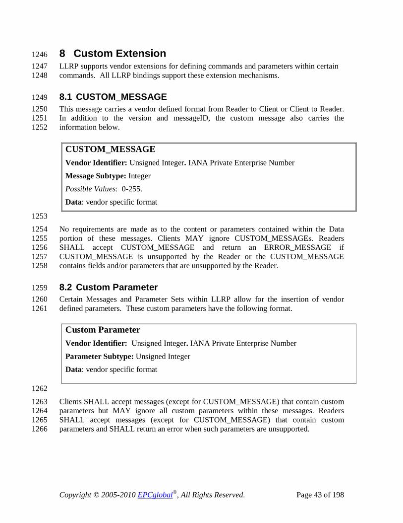
Copyright © 2005-2010 EPCglobal®, All Rights Reserved. Page 43 of 198
8 Custom Extension 1246 LLRP supports vendor extensions for defining commands and parameters within certain 1247 commands. All LLRP bindings support these extension mechanisms. 1248
8.1 CUSTOM_MESSAGE 1249 This message carries a vendor defined format from Reader to Client or Client to Reader. 1250 In addition to the version and messageID, the custom message also carries the 1251 information below. 1252
1253 No requirements are made as to the content or parameters contained within the Data 1254 portion of these messages. Clients MAY ignore CUSTOM_MESSAGEs. Readers 1255 SHALL accept CUSTOM_MESSAGE and return an ERROR_MESSAGE if 1256 CUSTOM_MESSAGE is unsupported by the Reader or the CUSTOM_MESSAGE 1257 contains fields and/or parameters that are unsupported by the Reader. 1258
8.2 Custom Parameter 1259 Certain Messages and Parameter Sets within LLRP allow for the insertion of vendor 1260 defined parameters. These custom parameters have the following format. 1261
1262
Clients SHALL accept messages (except for CUSTOM_MESSAGE) that contain custom 1263 parameters but MAY ignore all custom parameters within these messages. Readers 1264 SHALL accept messages (except for CUSTOM_MESSAGE) that contain custom 1265 parameters and SHALL return an error when such parameters are unsupported. 1266
CUSTOM_MESSAGE Vendor Identifier: Unsigned Integer. IANA Private Enterprise Number
Message Subtype: Integer Possible Values: 0-255.
Data: vendor specific format
Custom Parameter Vendor Identifier: Unsigned Integer. IANA Private Enterprise Number
Parameter Subtype: Unsigned Integer Data: vendor specific format

Copyright © 2005-2010 EPCglobal®, All Rights Reserved. Page 44 of 198
8.3 Custom Extension in Commands 1267 The following commands allow one or more custom Parameters in their message 1268 structure: 1269
GET_READER_CAPABILITIES 1270 GET_READER_CONFIG 1271
GET_READER_CAPABILITIES_RESPONSE 1272 GET_READER_CONFIG_RESPONSE 1273
SET_READER_CONFIG 1274
8.4 Custom Extension in Individual LLRP Parameters 1275 LLRP only allows extension to parameters where the parameter set is defined with a 1276 custom Parameter type in the abstract model. All custom extension points will be marked 1277 in the abstract standard using the notation 1278
1279 Custom Extension Point List: List of <custom Parameter> [optional] 1280 The following example illustrates a fictitious parameter that allows the embedding of 1281 custom extension parameters. 1282
Example Parameter Field1: Unsigned Integer
relatedData: Example Sub Parameter Custom Extension Point List: List of <custom Parameter> [optional]
1283 This example shows that the Example Parameter could contain an optional custom 1284 parameter that must adhere to the custom Parameter format. 1285
8.5 Allowable Parameter Extension 1286 All parameter values are specified within the abstract binding. A Reader or Client 1287 SHALL NOT extend the range of fields defined within the abstract specification unless 1288 the possible values indicate ranges for user defined options. 1289 For example, the Indentification Parameter defines a field to carry the ID type. 1290
IDType: Integer 1291 Possible Values: 1292 IDType ID 1293 ------ -- 1294 0 MAC address 1295 1 EPC 1296 1297

Copyright © 2005-2010 EPCglobal®, All Rights Reserved. Page 45 of 198
A Client or Reader adhering to the standard SHALL generate an IDType field with only 1298 those values shown (0-1). A Reader or Client implementation SHALL generate an error 1299 upon receiving a value outside this range. 1300
9 Protocol Version Management 1301 The messages within this category deal with the discovery of supported protocol 1302 versions, and the selection of a protocol version for the current LLRP connection. This 1303 sequence is referred to as version negotiation. For the purposes of version negotiation, 1304 the definition of a LLRP connection is left to the underlying transport layer (see section 1305 20.1 more information). 1306
9.1 Messages 1307
9.1.1 GET_SUPPORTED_VERSION 1308 This message is sent from the Client to the Reader. Clients MAY send this message at 1309 any time during a LLRP connection. 1310 Because this message is used for version negotiation and this procedure was introduced 1311 in LLRP 1.1 (version 2), this message SHALL be sent with its Ver field set to 2 prior to a 1312 successfully negotiated protocol version. Once a protocol version has been established, 1313 this message SHALL be sent with the negotiated version. Clients that receive an 1314 ERROR_MESSAGE in response to this message with a StatusCode of 1315 M_UnsupportedVersion SHALL assume the Reader only supports LLRP 1.0.1 (version 1316 1). 1317
Compliance requirement: Compliant Readers and Clients SHALL implement this 1318 message. 1319
GET_SUPPORTED_VERSION 1320
9.1.2 GET_SUPPORTED_VERSION_RESPONSE 1321 This is the response message from the Reader to the GET_SUPPORTED_VERSION 1322 message. The response contains the LLRPStatus Parameter and the version information 1323 supported by the Reader. The SupportedVersion field is inclusive starting with LLRP 1324 version 1.0.1 (version 1). For example, as advertised SupportedVersion value of 5 by the 1325 Reader SHALL indicate that the Reader supports versions [1-5] inclusive. 1326
Because this message is used for version negotiation and this procedure was introduced 1327 in LLRP 1.1 (version 2), this message SHALL be sent with its Ver field set to 2 prior to a 1328 successfully negotiated protocol version. Once a protocol version has been established, 1329 this message SHALL be sent with the negotiated version. 1330
Compliance requirement: Compliant Readers and Clients SHALL implement this 1331 message. 1332

Copyright © 2005-2010 EPCglobal®, All Rights Reserved. Page 46 of 198
GET_SUPPORTED_VERSION_RESPONSE Response: LLRPStatus Parameter
CurrentVersion: Unsigned Byte. The currently negotiated protocol version. SupportedVersion: Unsigned Byte. The maximum supported protocol version.
1333
9.1.3 SET_PROTOCOL_VERSION 1334 This message is sent from the Client to the Reader to set the protocol version for the 1335 current connection. Clients SHALL send this message either zero or one times during a 1336 LLRP connection, assuming the SET_PROTOCOL_VERSION_RESPONSE from the 1337 Reader indicates that the protocol selection was successful. Once a successful protocol 1338 version has been established this message SHALL not be sent again. 1339
Because this message is used for version negotiation and this procedure was introduced 1340 in LLRP 1.1 (version 2), this message SHALL be sent with its Ver field set to 2. Clients 1341 that receive an ERROR_MESSAGE in response to this message with a StatusCode of 1342 M_UnsupportedVersion SHALL assume the Reader only supports LLRP 1.0.1 (version 1343 1). 1344 Compliance requirement: Compliant Readers and Clients SHALL implement this 1345 message. 1346
SET_PROTOCOL_VERSION ProtocolVersion: Unsigned Byte. The desired protocol version.
1347
9.1.4 SET_PROTOCOL_VERSION_RESPONSE 1348 This is the response message from the Reader to the SET_PROTOCOL_VERSION 1349 message. The response contains only the LLRPStatus Parameter. If the version requested 1350 by the Client is not supported by the Reader, the Reader SHALL respond with an 1351 LLRPStatus StatusCode of M_UnsupportedVersion, and no sub-parameters (such as 1352 FieldError or ParameterError). If a negotiated version has already been established by a 1353 successful SET_PROTOCOL_VERSION message, the Reader SHALL respond with a 1354 StatusCode of M_UnexpectedMessage. If the Client requests protocol version 1, the 1355 Reader SHALL respond with a StatusCode of M_Success. 1356 Because this message is used for version negotiation and this procedure was introduced 1357 in LLRP 1.1 (version 2), this message SHALL be sent with its Ver field set to 2. 1358 Compliance requirement: Compliant Readers and Clients SHALL implement this 1359 message. 1360
SET_PROTOCOL_VERSION_RESPONSE Response: LLRPStatus Parameter.
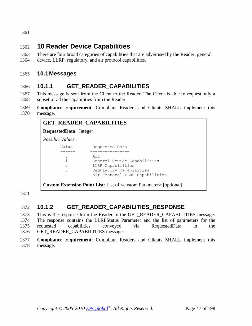
Copyright © 2005-2010 EPCglobal®, All Rights Reserved. Page 47 of 198
1361
10 Reader Device Capabilities 1362 There are four broad categories of capabilities that are advertised by the Reader: general 1363 device, LLRP, regulatory, and air protocol capabilities. 1364
10.1 Messages 1365
10.1.1 GET_READER_CAPABILITIES 1366 This message is sent from the Client to the Reader. The Client is able to request only a 1367 subset or all the capabilities from the Reader. 1368
Compliance requirement: Compliant Readers and Clients SHALL implement this 1369 message. 1370
GET_READER_CAPABILITIES RequestedData: Integer
Possible Values: Value Requested Data ------ ---------------- 0 All 1 General Device Capabilities 2 LLRP Capabilities 3 Regulatory Capabilities 4 Air Protocol LLRP Capabilities Custom Extension Point List: List of <custom Parameter> [optional]
1371
10.1.2 GET_READER_CAPABILITIES_RESPONSE 1372 This is the response from the Reader to the GET_READER_CAPABILITIES message. 1373 The response contains the LLRPStatus Parameter and the list of parameters for the 1374 requested capabilities conveyed via RequestedData in the 1375 GET_READER_CAPABILITIES message. 1376
Compliance requirement: Compliant Readers and Clients SHALL implement this 1377 message. 1378

Copyright © 2005-2010 EPCglobal®, All Rights Reserved. Page 48 of 198
10.2 Parameters 1379
10.2.1 GeneralDeviceCapabilities Parameter 1380 This parameter carries the general capabilities of the device like supported air protocols, 1381 version of the Reader firmware, device hardware and software information, and receive 1382 sensitivity table. 1383 Compliance requirement: Compliant Readers and Clients SHALL implement this 1384 parameter. 1385
GeneralDeviceCapabilities Parameter Device manufacturer name: Unsigned Integer. The IANA Private Enterprise Number (PEN). Model name: Unsigned Integer
Firmware version: UTF-8 String Maximum number of antennas supported: Unsigned Short Integer
CanSetAntennaProperties: Boolean. If set to true, the Client can set antenna properties (Section 13.2.5), else, the Client can not set it, but only query it using GET_READER_ CONFIG. Maximum Receive Sensitivity: <MaximumReceiveSensitivity Parameter> [optional]
Receive Sensitivity Table: List of <ReceiveSensitivityTableEntry Parameter> Per Antenna Receive Sensitivity Range: List of <PerAntennaReceiveSensivityRange Parameter> Air protocol supported per antenna: N instances of<PerAntennaAirProtocol Parameter>, where N = Maximum number of antennae supported. GPIO Support: <GPIO Capabilities Parameter>
GET_READER_CAPABILITIES_RESPONSE Response Data: Set of LLRP Parameters. Possible Values: The possible members are
<LLRPStatus Parameter>, and, one or more from the set
< GeneralDeviceCapabilities Parameter, LLRPCapabilities Parameter,
RegulatoryCapabilities Parameter, AirProtocolLLRPCapabilities Parameter >.
Custom Extension Point List: List of <custom Parameter> [optional]
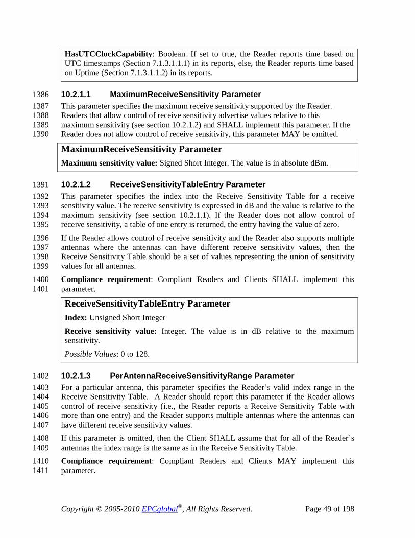
Copyright © 2005-2010 EPCglobal®, All Rights Reserved. Page 49 of 198
HasUTCClockCapability: Boolean. If set to true, the Reader reports time based on UTC timestamps (Section 7.1.3.1.1.1) in its reports, else, the Reader reports time based on Uptime (Section 7.1.3.1.1.2) in its reports.
10.2.1.1 MaximumReceiveSensitivity Parameter 1386 This parameter specifies the maximum receive sensitivity supported by the Reader. 1387 Readers that allow control of receive sensitivity advertise values relative to this 1388 maximum sensitivity (see section 10.2.1.2) and SHALL implement this parameter. If the 1389 Reader does not allow control of receive sensitivity, this parameter MAY be omitted. 1390
MaximumReceiveSensitivity Parameter Maximum sensitivity value: Signed Short Integer. The value is in absolute dBm.
10.2.1.2 ReceiveSensitivityTableEntry Parameter 1391 This parameter specifies the index into the Receive Sensitivity Table for a receive 1392 sensitivity value. The receive sensitivity is expressed in dB and the value is relative to the 1393 maximum sensitivity (see section 10.2.1.1). If the Reader does not allow control of 1394 receive sensitivity, a table of one entry is returned, the entry having the value of zero. 1395 If the Reader allows control of receive sensitivity and the Reader also supports multiple 1396 antennas where the antennas can have different receive sensitivity values, then the 1397 Receive Sensitivity Table should be a set of values representing the union of sensitivity 1398 values for all antennas. 1399 Compliance requirement: Compliant Readers and Clients SHALL implement this 1400 parameter. 1401
ReceiveSensitivityTableEntry Parameter Index: Unsigned Short Integer
Receive sensitivity value: Integer. The value is in dB relative to the maximum sensitivity.
Possible Values: 0 to 128.
10.2.1.3 PerAntennaReceiveSensitivityRange Parameter 1402 For a particular antenna, this parameter specifies the Reader’s valid index range in the 1403 Receive Sensitivity Table. A Reader should report this parameter if the Reader allows 1404 control of receive sensitivity (i.e., the Reader reports a Receive Sensitivity Table with 1405 more than one entry) and the Reader supports multiple antennas where the antennas can 1406 have different receive sensitivity values. 1407 If this parameter is omitted, then the Client SHALL assume that for all of the Reader’s 1408 antennas the index range is the same as in the Receive Sensitivity Table. 1409 Compliance requirement: Compliant Readers and Clients MAY implement this 1410 parameter. 1411

Copyright © 2005-2010 EPCglobal®, All Rights Reserved. Page 50 of 198
PerAntennaReceiveSensitivityRange Parameter Antenna ID: Unsigned Short Integer
Possible Values: 1 to N, where N is the maximum number of antennas supported by the device.
ReceiveSensitivityIndexMin: Unsigned Short Integer Possible Values:
0 to S, where S is the number of Receive Sensitivity Table entries reported by the Reader.
ReceiveSensitivityIndexMax: Unsigned Short Integer Possible Values:
Mn to S, where Mn is the ReceiveSensitivityIndexMin and S is the number of Receive Sensitivity Table entries reported by the Reader.
10.2.1.4 PerAntennaAirProtocol Parameter 1412 Compliance requirement: Compliant Readers and Clients SHALL implement this 1413 parameter. 1414
PerAntennaAirProtocol Parameter Antenna ID: Unsigned Short Integer Possible Values:
1 to N, where N is the maximum number of antennas supported by the device. Air protocols supported: List of Protocol Ids enumerated based on Table 4.
10.2.1.5 GPIOCapabilities Parameter 1415 This parameter describes the GPIO capabilities of the Reader. A value of zero for 1416 NumGPIs indicates that the Reader does not have general purpose inputs. A value of zero 1417 for NumGPOs indicates that the Reader does not have general purpose outputs. 1418 1419 Compliance requirement: Compliant Readers and Clients SHALL implement this 1420 parameter. 1421
GPIOCapabilities Parameter NumGPIs: Unsigned Short Integer. Number of general purpose inputs supported by the device. NumGPOs: Unsigned Short Integer. Number of general purpose outputs supported by the device.

Copyright © 2005-2010 EPCglobal®, All Rights Reserved. Page 51 of 198
10.2.2 LLRPCapabilities Parameter 1422 This parameter describes the LLRP protocol capabilities of the Reader. These include 1423 optional LLRP commands and parameters, capacities of data structures used in LLRP 1424 operations, and air protocol specific capabilities used by LLRP. 1425 Compliance requirement: Compliant Readers and Clients SHALL implement this 1426 parameter. Readers MAY support RFSurvey, MAY support tag inventory state aware 1427 singulation, MAY support UTC clocks, MAY support buffer fill warning reports, MAY 1428 support EventAndReportHolding upon reconnect, and MAY support 1429 ClientRequestOpspec. Readers SHALL support at least one ROSpec, one AISpec per 1430 ROSpec, one InventoryParameterSpec per AISpec, one AccessSpec, and one OpSpec per 1431 AccessSpec. 1432
LLRPCapabilities Parameter CanDoRFSurvey: Boolean. If set to true, the Reader can perform RFSurvey operations (Section 11.2.3).
CanDoTagInventoryStateAwareSingulation: Boolean. If set to true, the Reader can support tag inventory state aware singulation.
CanReportBufferFillWarning: Boolean. If set to true, the Reader can report buffer fill warning in the reader event notification (Section 14.2.6.5).
MaxNumROSpecs: Integer. If zero, there is no limit. This is the maximum number of ROSpecs that can be configured at the Reader.
MaxNumSpecsPerROSpec: Integer. If zero, there is no limit. This is the maximum number of Specs (either AISpec or RFSurveySpec) that can be configured as part of a ROSpec at the Reader. MaxNumInventoryParameterSpecsPerAISpec: Integer. If zero, there is no limit. This is the maximum number of InventoryParameterSpecs that can be configured per AISpec.
MaxPriorityLevelSupported: Integer. This is the maximum priority level supported in the reader. If set to less than or equal to 1, the Reader has no preemption support.
Possible Values: 0-7. MaxNumAccessSpecs: Integer. If zero, there is no limit. This is the maximum number of AccessSpecs that can be configured at the Reader. MaxNumOpSpecsPerAccessSpec: Integer. If zero, there is no limit. This is the maximum number of OpSpecs that can be configured per AccessSpec at the Reader. SupportsClientRequestOpSpec: Boolean. If set to true, the Reader supports client request OpSpecs (Section 12.2.1.2.1). ClientRequestOpSpecTimeout: Unsigned Short Integer (in milliseconds). The time the Reader will wait for the CLIENT_REQUEST_OP_RESPONSE from the Client after sending a RO_ACCESS_REPORT message upon executing the ClientRequestOpSpec OpSpec. This field is valid only if the Reader supports ClientRequestOpSpec (Section

Copyright © 2005-2010 EPCglobal®, All Rights Reserved. Page 52 of 198
12.2.1.2.1). If this field is 0, there is no limit.
SupportsEventAndReportHolding: Boolean. If set to True, the Reader supports the EventsAndReports Parameter and the ENABLE_EVENTS_AND_REPORTS message. If set to false, the Reader does not support the ENABLE_EVENTS_AND_REPORTS message or the EventsAndReports Parameter.
10.2.3 AirProtocolLLRPCapabilities Parameter 1433 Compliance requirement: Compliant Readers and Clients SHALL implement this 1434 parameter. 1435
AirProtocolLLRPCapabilities Parameter Each air protocol’s capabilities are expressed in a different LLRP Parameter. Each protocol’s air protocol capabilities parameter SHALL be referenced not more than once. The air protocol specific capabilities LLRP Parameters are defined in section 16.1.
10.2.4 RegulatoryCapabilities Parameter 1436 This parameter carries the RF regulation specific attributes. They include regulatory 1437 standard, frequency band information, power levels supported, frequencies supported, 1438 and any air protocol specific values that are determined based on regulatory restriction. 1439 The regulatory standard is encoded using two Integer fields, <Country Code, 1440 Communications standard> and it specifies the current operational regulatory mode of the 1441 device. This should not be used to reflect the ability to operate in regulatory 1442 environments which require configuration different from the current. This version of the 1443 LLRP protocol will have support for only the UHF band. 1444 Compliance requirement: Compliant Readers and Clients SHALL implement this 1445 parameter. 1446
RegulatoryCapabilities Parameter Country Code: Unsigned Short Integer. This field carries the numeric code of the country as specified in ISO 3166 [ISO3166]. 0 means unspecified.
Communications Standard: Unsigned Short Integer. This field carries the enumerations of the communications standard as specified below.
Possible Values: Value Communications Standard ------ -------------------------
0 Unspecified 1 US FCC Part 15
2 ETSI 302-208 3 ETSI 300-220
4 Australia LIPD 1W 5 Australia LIPD 4W 6 Japan: ARIB STD T89 7 Hong Kong: OFTA 1049 8 Taiwan: DGT LP0002 9 Korea: MIC Article 5-2

Copyright © 2005-2010 EPCglobal®, All Rights Reserved. Page 53 of 198
10 902-928 MHz 4W Freq Hop 11 ETSI 302-208 2W without LBT 12 Brazil 902-907.5 MHz 4W Freq Hop 13 China 840.5-844.5 MHz 2W Freq Hop 14 China 920.5-924.5 MHz 2W Freq Hop 15 Hong Kong, China 920-925 MHz 4W 16 Israel 915-917 MHz 17 Japan 952-954 MHz 4W LBT 18 Japan 952-955 MHz 20mW LBT 19 865-868 MHz 0.5W 20 Korea, Rep. 917-920.8 MHz 4W HFSS or LBT 21 Korea, Rep. 917-923.5 MHz 200mW HFSS or LBT 22 Malaysia 866-869 MHz 23 Malaysia 919-923 MHz 2W 24 New Zealand 864-868 MHz 4W 25 Singapore 866-869 MHz 0.5W 26 Singapore 920-925 MHz 2W 27 South Africa 915.4-919 MHz 4W Freq Hop 28 South Africa 919.2-921 MHz 4W nonmodulated 29 Taiwan 922-928 MHz 1W Freq Hop 30 Taiwan 922-928 MHz 0.5W Freq Hop 31 Thailand 920-925 MHz 4W Freq Hop 32 Venezula 922-928 MHz 33 Vietnam 866-869 MHz 0.5W 34 Vietnam 920-925 MHz 2W 35–65535 Reserved for future use UHFBandCapabilities: <UHFBandCapabilities Parameter> [optional]
Custom Extension Point List: List of <custom Parameter> [optional]
10.2.4.1 UHFBandCapabilities Parameter 1447 Compliance requirement: Compliant Readers and Clients SHALL implement this 1448 parameter. 1449
UHFBandCapabilities Parameter TransmitPowerTable: List of <TransmitPowerLevelTableEntry Parameter> Frequency Information: <FrequencyInformation Parameter>
RFSurveyFrequencyCapabilities: <RFSurveyFrequencyCapabilities Parameter> [optional]
UHF_RFModeTable: List of LLRP Parameter. Possible Values:
Each air protocol’s UHF RF mode table is expressed as a different LLRP parameter. Each protocol SHALL be referenced not more than once. The air protocol’s UHF RF mode table capabilities LLRP Parameters are defined in section 16.1.
10.2.4.1.1 TransmitPowerLevelTableEntry Parameter 1450

Copyright © 2005-2010 EPCglobal®, All Rights Reserved. Page 54 of 198
This parameter specifies the index into the TransmitPowerLevelTable for a transmit 1451 power value. The transmit power is expressed in dBm*100 to allow fractional dBm 1452 representation and is the conducted power at the connector of the Reader. 1453 Compliance requirement: Compliant Readers and Clients SHALL implement this 1454 parameter. 1455
TransmitPowerLevelTableEntry Parameter Index: Integer Possible Values: 0-255
Transmit power value: Signed short integer. Transmit power expressed in dBm*100 to allow fractional dBm representation.
10.2.4.1.2 FrequencyInformation Parameter 1456 Compliance requirement: Compliant Readers and Clients SHALL implement this 1457 parameter. 1458
Frequency Information Parameter Hopping: Boolean Freq Hop Info: Zero or more instances of <FrequencyHopTable Parameter>. This is transmitted only when Hopping = true. Fixed Freq Info: At most one instance of <FixedFrequencyTable>. This is transmitted only when Hopping = false.
10.2.4.1.2.1 FrequencyHopTable Parameter 1459 This parameter carries the frequency hop table parameters. This is used for Readers 1460 operating in regions with frequency hopping regulatory requirements. If the Reader is 1461 capable of storing multiple hop tables, the Reader may send all of them to the Client. 1462 Each hop table contains: 1463
• HopTableID which is the index of the frequency hop table returned by the Reader. 1464
• This is followed by a list of the frequencies (in kHz) in hop table order. The one-1465 based position of a frequency in the list is defined as its ChannelIndex (i.e. the 1466 first frequency is referred to as ChannelIndex one). 1467
Compliance requirement: Compliant Readers and Clients SHALL implement this 1468 parameter when operating in frequency hopping regulatory regions. 1469
FrequencyHopTable Parameter HopTableID : Integer Possible Values: 0 - 255
Frequency Hop List: List of unsigned integers. Frequency in kHz.

Copyright © 2005-2010 EPCglobal®, All Rights Reserved. Page 55 of 198
If multiple frequency hop tables are supported by the Reader, each table can be sent using 1470 a separate Frequency Hop Table Parameter. 1471
10.2.4.1.2.2 FixedFrequencyTable Parameter 1472 This parameter carries the fixed frequency list that can be used by the Reader. The one-1473 based position of a frequency in the list is defined as its ChannelIndex (i.e. the first 1474 frequency is referred to as ChannelIndex one). 1475
Compliance requirement: Compliant Readers and Clients SHALL implement this 1476 parameter when operating in fixed frequency regulatory regions. 1477
Fixed Frequency Parameter Frequency List: List of unsigned integers. Frequency in kHz.
10.2.4.1.3 RFSurveyFrequencyCapabilities Parameter 1478 This parameter describes the Reader’s range of supported receive frequencies. This 1479 specifies the lower and upper limit of frequencies allowed in an RFSurveySpec. 1480 1481 Compliance requirement: Compliant Readers and Clients SHALL implement this 1482 parameter if CanDoRFSurvey is reported as “true” in the LLRPCapabilties parameter. 1483
RFSurveyFrequencyCapabilities Parameter MinimumFrequency: Unsigned Integer. Minimum receive frequency (in kHz) supported by the Reader.
MaximumFrequency: Unsigned Integer. Maximum receive frequency (in kHz) supported by the Reader.
11 Reader Operation (RO) 1484 This section presents the messages and the parameters used by the Client for specifying 1485 RO. 1486
11.1 Messages 1487
11.1.1 ADD_ROSPEC 1488 An ADD_ROSPEC message communicates the information of a ROSpec to the Reader. 1489 LLRP supports configuration of multiple ROSpecs. Each ROSpec is uniquely identified 1490 using a ROSpecID, generated by the Client. The ROSpec starts at the Disabled state 1491 waiting for the ENABLE_ROSPEC message for the ROSpec from the Client, upon which 1492 it transitions to the Inactive state. 1493
The Client SHALL add a ROSpec in a Disabled State – i.e., CurrentState field in the 1494 ROSpec Parameter (section 11.2.1) SHALL be set to disabled. If the CurrentState value 1495 is different than disabled, an error SHALL be returned in the 1496 ADD_ROSPEC_RESPONSE (e.g. P_FieldError). 1497

Copyright © 2005-2010 EPCglobal®, All Rights Reserved. Page 56 of 198
Compliance requirement: Compliant Readers and Clients SHALL implement this 1498 message. 1499
ADD_ROSPEC ROSpec: ROSpec Parameter
11.1.2 ADD_ROSPEC_RESPONSE 1500 This is the response by the Reader to an ADD_ROSPEC message. If all the parameters 1501 specified in the ADD_ROSPEC command are successfully set, then the success code is 1502 returned in the LLRPStatus parameter. If there is an error, the appropriate error code is 1503 returned in the LLRPStatus parameter. 1504
Compliance requirement: Compliant Readers and Clients SHALL implement this 1505 message. 1506
ADD_ROSPEC_RESPONSE Response: LLRPStatus Parameter
11.1.3 DELETE_ROSPEC 1507 This command is issued by the Client to the Reader. This command deletes the ROSpec 1508 at the Reader corresponding to ROSpecID passed in this message. 1509
Compliance requirement: Compliant Readers and Clients SHALL implement this 1510 message. 1511
DELETE_ROSPEC ROSpecID: Unsigned Integer. The identifier of the ROSpec to delete. 0 indicates to delete all ROSpecs.
11.1.4 DELETE_ROSPEC_RESPONSE 1512 This is the response by the Reader to a DELETE_ROSPEC command. If there was a 1513 ROSpec corresponding to the ROSpecID that the Reader was presently executing, and 1514 the Reader was successful in stopping that execution, then the success code is returned in 1515 the LLRPStatus parameter. If there is an error, the appropriate error code is returned in 1516 the LLRPStatus parameter. 1517
Compliance requirement: Compliant Readers and Clients SHALL implement this 1518 message. 1519
DELETE_ROSPEC_RESPONSE Response: LLRPStatus Parameter
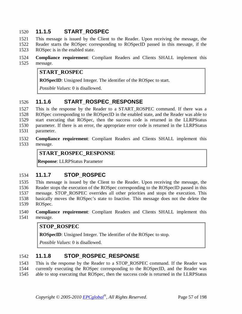
Copyright © 2005-2010 EPCglobal®, All Rights Reserved. Page 57 of 198
11.1.5 START_ROSPEC 1520 This message is issued by the Client to the Reader. Upon receiving the message, the 1521 Reader starts the ROSpec corresponding to ROSpecID passed in this message, if the 1522 ROSpec is in the enabled state. 1523 Compliance requirement: Compliant Readers and Clients SHALL implement this 1524 message. 1525
START_ROSPEC ROSpecID: Unsigned Integer. The identifier of the ROSpec to start.
Possible Values: 0 is disallowed.
11.1.6 START_ROSPEC_RESPONSE 1526 This is the response by the Reader to a START_ROSPEC command. If there was a 1527 ROSpec corresponding to the ROSpecID in the enabled state, and the Reader was able to 1528 start executing that ROSpec, then the success code is returned in the LLRPStatus 1529 parameter. If there is an error, the appropriate error code is returned in the LLRPStatus 1530 parameter. 1531
Compliance requirement: Compliant Readers and Clients SHALL implement this 1532 message. 1533
START_ROSPEC_RESPONSE Response: LLRPStatus Parameter
11.1.7 STOP_ROSPEC 1534 This message is issued by the Client to the Reader. Upon receiving the message, the 1535 Reader stops the execution of the ROSpec corresponding to the ROSpecID passed in this 1536 message. STOP_ROSPEC overrides all other priorities and stops the execution. This 1537 basically moves the ROSpec’s state to Inactive. This message does not the delete the 1538 ROSpec. 1539
Compliance requirement: Compliant Readers and Clients SHALL implement this 1540 message. 1541
STOP_ROSPEC ROSpecID: Unsigned Integer. The identifier of the ROSpec to stop.
Possible Values: 0 is disallowed.
11.1.8 STOP_ROSPEC_RESPONSE 1542 This is the response by the Reader to a STOP_ROSPEC command. If the Reader was 1543 currently executing the ROSpec corresponding to the ROSpecID, and the Reader was 1544 able to stop executing that ROSpec, then the success code is returned in the LLRPStatus 1545

Copyright © 2005-2010 EPCglobal®, All Rights Reserved. Page 58 of 198
parameter. If there is an error, the appropriate error code is returned in the LLRPStatus 1546 parameter. 1547
Compliance requirement: Compliant Readers and Clients SHALL implement this 1548 message. 1549
STOP_ROSPEC_RESPONSE Response: LLRPStatus Parameter
11.1.9 ENABLE_ROSPEC 1550 This message is issued by the Client to the Reader. Upon receiving the message, the 1551 Reader moves the ROSpec corresponding to the ROSpecID passed in this message from 1552 the disabled to the inactive state. 1553 Compliance requirement: Compliant Readers and Clients SHALL implement this 1554 message. 1555
ENABLE_ROSPEC ROSpecID: Unsigned Integer. The identifier of the ROSpec to enable. If set to 0, all ROSpecs are enabled.
11.1.10 ENABLE_ROSPEC_RESPONSE 1556 This is the response by the Reader to a ENABLE_ROSPEC command. If there was a 1557 ROSpec corresponding to the ROSpecID, and the Reader was able to enable that 1558 ROSpec, then the success code is returned in the LLRPStatus parameter. If there is an 1559 error, the appropriate error code is returned in the LLRPStatus parameter. 1560
Compliance requirement: Compliant Readers and Clients SHALL implement this 1561 message. 1562
ENABLE_ROSPEC_RESPONSE Response: LLRPStatus Parameter
11.1.11 DISABLE_ROSPEC 1563 This message is issued by the Client to the Reader. Upon receiving the message, the 1564 Reader moves the ROSpec corresponding to the ROSpecID passed in this message to the 1565 disabled state. 1566
Compliance requirement: Compliant Readers and Clients SHALL implement this 1567 message. 1568
DISABLE_ROSPEC ROSpecID: Unsigned Integer. The identifier of the ROSpec to disable. If set to 0, all ROSpecs are disabled.

Copyright © 2005-2010 EPCglobal®, All Rights Reserved. Page 59 of 198
11.1.12 DISABLE_ROSPEC_RESPONSE 1569 This is the response by the Reader to a DISABLE_ROSPEC command. If there was a 1570 ROSpec corresponding to the ROSpecID, and the Reader was able to disable that 1571 ROSpec, then the success code is returned in the LLRPStatus parameter. If there is an 1572 error, the appropriate error code is returned in the LLRPStatus parameter. 1573
Compliance requirement: Compliant Readers and Clients SHALL implement this 1574 message. 1575
DISABLE_ROSPEC_RESPONSE Response: LLRPStatus Parameter
11.1.13 GET_ROSPECS 1576 This is the request from the Client to the Reader to retrieve all the ROSpecs that have 1577 been configured at the Reader. 1578 Compliance requirement: Compliant Readers and Clients SHALL implement this 1579 message. 1580
GET_ROSPECS
11.1.14 GET_ROSPECS_RESPONSE 1581 This is the response by the Reader to a GET_ROSPECS command. If there are no 1582 ROSpecs configured at the Reader, the response is just the LLRPStatus parameter with 1583 the success code. Else, a list of ROSpec parameter is returned by the Reader, along with 1584 the success code in the LLRPStatus parameter. 1585
Compliance requirement: Compliant Readers and Clients SHALL implement this 1586 message. 1587
GET_ROSPECS_RESPONSE Status: LLRPStatus Parameter Response: List of <ROSpec Parameter> that are in the order in which they are added.
11.2 Parameters 1588
11.2.1 ROSpec Parameter 1589 This parameter carries the information of the Reader inventory and survey operation. 1590
Compliance requirement: Compliant Readers and Clients SHALL implement this 1591 parameter. 1592

Copyright © 2005-2010 EPCglobal®, All Rights Reserved. Page 60 of 198
ROSpec Parameter ROSpecID: Unsigned Integer; 0 is an illegal ROSpecID for a ROSpec.
Priority: Integer. Lower numbered priority values are given higher priority. Possible Values: 0-7.
CurrentState: Integer Possible Values: Value Definition ----- ---------- 0 Disabled 1 Inactive 2 Active
ROBoundarySpec: ROBoundarySpec Parameter ListOfSpecs: List of LLRP Parameters
Possible Values: Each parameter can be either an <AISpec Parameter>, a <RFSurveySpec Parameter>, a <LoopSpec Parameter>, or a Custom Parameter.
ROReportSpec: ROReportSpec Parameter [optional] (Section 14.2.1)
11.2.1.1 ROBoundarySpec Parameter 1593 This parameter carries the lifetime of the command, ROStartTrigger and ROStopTrigger 1594 parameters. 1595 Compliance requirement: Compliant Readers and Clients SHALL implement this 1596 parameter. 1597
ROBoundarySpec Parameter ROSpecStartTrigger: ROSpecStartTrigger Parameter
ROSpecStopTrigger: ROSpecStopTrigger Parameter
11.2.1.1.1 ROSpecStartTrigger Parameter 1598 Compliance requirement: Compliant Readers and Clients SHALL implement this 1599 parameter. 1600
ROSpecStartTrigger Parameter ROSpecStartTriggerType: Integer
Possible Values: Value Definition ----- ---------- 0 Null – No start trigger. The only way to start the ROSpec is with a START_ROSPEC from the Client.

Copyright © 2005-2010 EPCglobal®, All Rights Reserved. Page 61 of 198
1 Immediate 2 Periodic 3 GPI PeriodicTriggerValue: PeriodicTriggerValue Parameter [Optional]. This parameter SHALL be present when ROSpecStartTriggerType = 2.
GPITriggerValue: GPITriggerValue Parameter [Optional]. This parameter SHALL be present when ROSpecStartTriggerType = 3.
11.2.1.1.1.1 PeriodicTriggerValue Parameter 1601 Periodic trigger is specified using UTC time, offset and period. 1602 For one-shot inventory, period is set to 0, and for periodic inventory operation period > 0. 1603
If UTC time is not specified, the first start time is determined as (time of message receipt 1604 + offset), else, the first start time is determined as (UTC time + offset). Subsequent start 1605 times = first start time + k * period (where, k > 0). 1606 If the Reader does not support UTC clock (as indicated by HasUTCClockCapability), and 1607 it receives the UTC time as part of the PeriodicTriggerValue parameter from the Client, 1608 the Reader SHALL return an error. 1609
Compliance requirement: Compliant Readers and Clients SHALL implement this 1610 parameter. Compliant Readers and Clients MAY implement the UTCTimestamp 1611 parameter. 1612
PeriodicTriggerValue Parameter UTC Time: <UTCTimestamp Parameter> [Optional] Offset: Unsigned Integer. Time offset specified in milliseconds.
Period: Unsigned Integer. Time period specified in milliseconds
11.2.1.1.1.2 GPITriggerValue Parameter 1613 This trigger is tied to an event on the General Purpose Input (GPI) of the Reader. The 1614 event is represented as a boolean type, and it is up to the internal implementation of the 1615 Reader to map exact physical event to a boolean type. For example, a 0 1 and a 1 0 1616 transition on an input pin of the Reader could be mapped to a boolean true and a boolean 1617 false event respectively. 1618
This trigger parameter has a timeout value field. The timeout is useful for specifying a 1619 fail-safe timeout when this trigger is used as a stop trigger. When the timeout is 0, it 1620 indicates that there is no timeout. When used as a start trigger, the timeout value SHALL 1621 be ignored. 1622
Compliance requirement: Compliant Readers and Clients SHALL implement this 1623 parameter. Readers that do not support GPIs SHALL return zero for numGPIs in the 1624 capabilities discovery. If the Client sets up the GPI trigger for such a Reader, the Reader 1625 SHALL send an error message for the ADD_ROSPEC message and not add the ROSpec. 1626
GPITriggerValue Parameter

Copyright © 2005-2010 EPCglobal®, All Rights Reserved. Page 62 of 198
GPIPortNum: Unsigned Short Integer.
Possible Values: 1-65535. Zero is invalid. GPIEvent: Boolean. The Boolean value that causes a GPI event to trigger.
Timeout: Unsigned Integer. Trigger timeout in milliseconds. If set to zero, it indicates there is no timeout.
11.2.1.1.2 ROSpecStopTrigger Parameter 1627 Compliance requirement: Compliant Readers and Clients SHALL implement this 1628 parameter. 1629
ROSpecStopTrigger Parameter ROSpecStopTriggerType: Integer Possible Values: Value Definition ----- ---------- 0 Null – Stop when all Specs are done (including any looping as required by a LoopSpec parameter), or when preempted, or with a STOP_ROSPEC from the Client. 1 Duration – Stop after DurationTriggerValue milliseconds, or when all Specs are done (including any looping as required by a LoopSpec parameter), or when preempted, or with a STOP_ROSPEC from the Client. 2 GPI with a timeout value – Stop when a GPI "fires", or after Timeout milliseconds, or when all Specs are done (including any looping as required by a LoopSpec parameter), or when preempted, or with a STOP_ROSPEC from the Client. DurationTriggerValue: Duration in milliseconds. This field is ignored when ROSpecStopTriggerType != 1.
GPITriggerValue: GPITriggerValue Parameter [Optional]. This parameter SHALL be present when ROSpecStopTriggerType = 2.
11.2.2 AISpec Parameter 1630 This parameter defines antenna inventory operations. 1631
Compliance Requirement: Compliant Readers and Clients SHALL implement this 1632 parameter. 1633
AISpec Parameter AISpecStopTrigger: <AISpecStopTrigger Parameter> AntennaIDs: Short Array. If this set contains an antenna ID of zero, this AISpec will utilize all the antennas of the Reader. InventoryParameterSpecs: <List of InventoryParameterSpec Parameter>

Copyright © 2005-2010 EPCglobal®, All Rights Reserved. Page 63 of 198
Custom Extension Point List: List of <custom Parameter> [Optional]
11.2.2.1 AISpecStopTrigger Parameter 1634 This parameter defines the stop (i.e., terminating boundary) of an antenna inventory 1635 operation. 1636 Compliance Requirement: Compliant Readers and Clients SHALL implement this 1637 parameter. If a Reader reports NumGPIs (see GPIO Capabilities Parameter) greater than 1638 zero, then the Reader SHALL support GPI Trigger. 1639
AISpecStopTrigger Parameter AISpecStopTriggerType: Integer Possible Values: Value Definition ----- ---------- 0 Null – Stop when ROSpec is done. 1 Duration 2 GPI with a timeout value 3 Tag observation
Duration Trigger: Unsigned Integer. Duration of AISpec in milliseconds. This field SHALL be ignored when AISpecStopTriggerType != 1.
GPI Trigger : GPITrigger value Parameter [Optional]. This field SHALL be present when AISpecStopTriggerType = 2.
TagObservation Trigger : TagObservation Trigger Parameter [Optional]. This field SHALL be present when AISpecStopTriggerType = 3.
11.2.2.1.1 TagObservationTrigger Parameter 1640 Compliance requirement: Compliant Readers and Clients SHALL implement this 1641 parameter. 1642
Tag ObservationTrigger Parameter TriggerType: Integer Possible Values: Value Modulation ------ ------------ 0 Upon seeing N tag observations, or timeout. The definition of an "observation" is vendor specific. 1 Upon seeing no more new tag observations for T ms, or timeout. The definition of an "observation" is vendor specific. 2 N attempts to see all tags in the FOV, or timeout. 3 Upon seeing N unique tag observations, or timeout. 4 Upon seeing no more new unique tag observations for T ms, or timeout.

Copyright © 2005-2010 EPCglobal®, All Rights Reserved. Page 64 of 198
NumberOfTags: Unsigned Short Integer. This field SHALL be ignored when TriggerType != 0 and TriggerType != 3. NumberOfAttempts; Unsigned Short Integer. This field SHALL be ignored when TriggerType != 2. T : Unsigned Short Integer. Idle time between tag responses in milliseconds. This field SHALL be ignored when TriggerType != 1 and TriggerType != 4. Timeout : Unsigned Integer; Trigger timeout value in milliseconds. If set to zero, it indicates that there is no timeout.
11.2.2.2 InventoryParameterSpec Parameter 1643 This parameter defines the inventory operation to be performed at all antennas specified 1644 in the corresponding AISpec. This parameter is composed of 1645 an InventoryParameterSpecID, a ProtocolID, and zero or more optional antenna 1646 configuration parameters. Antenna configurations for antennas not indicated by the 1647 AntennaIDs within the AISpec are ignored by the reader. 1648 1649 Compliance Requirement: Compliant Readers and Clients SHALL implement this 1650 parameter. 1651
InventoryParameterSpec Parameter InventoryParameterSpecID: Unsigned Short Integer. 0 is illegal.
ProtocolID: Integer. Enumeration based on Table 4. AntennaConfiguration: List of <AntennaConfiguration Parameter> (Section 13.2.6) [Optional] Custom Extension Point List: List of <Custom Parameter> [Optional]
11.2.3 RFSurveySpec Parameter 1652 This parameter defines RF Survey operations. RF Survey is an operation during which 1653 the Reader performs a scan and measures the power levels across a set of frequencies at 1654 an antenna. This parameter defines the identifier of the antenna where this survey is to be 1655 performed, the duration of the survey operation (specified via stop trigger), and the range 1656 of frequencies to measure power levels of. 1657 Compliance Requirement: Compliant Readers and Clients MAY implement this 1658 parameter. 1659
RFSurveySpec Parameter Antenna ID: Unsigned Short Integer.
Possible Values: 1 to N, where N is the maximum number of antennas supported by the Reader.
RFSurveySpecStopTrigger: RFSurveySpecStopTrigger parameter
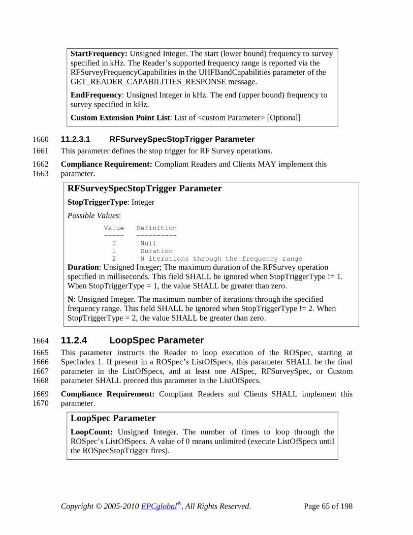
Copyright © 2005-2010 EPCglobal®, All Rights Reserved. Page 65 of 198
StartFrequency: Unsigned Integer. The start (lower bound) frequency to survey specified in kHz. The Reader’s supported frequency range is reported via the RFSurveyFrequencyCapabilities in the UHFBandCapabilities parameter of the GET_READER_CAPABILITIES_RESPONSE message. EndFrequency: Unsigned Integer in kHz. The end (upper bound) frequency to survey specified in kHz. Custom Extension Point List: List of <custom Parameter> [Optional]
11.2.3.1 RFSurveySpecStopTrigger Parameter 1660 This parameter defines the stop trigger for RF Survey operations. 1661 Compliance Requirement: Compliant Readers and Clients MAY implement this 1662 parameter. 1663
RFSurveySpecStopTrigger Parameter StopTriggerType: Integer
Possible Values: Value Definition ----- ---------- 0 Null 1 Duration 2 N iterations through the frequency range Duration: Unsigned Integer; The maximum duration of the RFSurvey operation specified in milliseconds. This field SHALL be ignored when StopTriggerType != 1. When StopTriggerType = 1, the value SHALL be greater than zero.
N: Unsigned Integer. The maximum number of iterations through the specified frequency range. This field SHALL be ignored when StopTriggerType != 2. When StopTriggerType = 2, the value SHALL be greater than zero.
11.2.4 LoopSpec Parameter 1664 This parameter instructs the Reader to loop execution of the ROSpec, starting at 1665 SpecIndex 1. If present in a ROSpec’s ListOfSpecs, this parameter SHALL be the final 1666 parameter in the ListOfSpecs, and at least one AISpec, RFSurveySpec, or Custom 1667 parameter SHALL preceed this parameter in the ListOfSpecs. 1668
Compliance Requirement: Compliant Readers and Clients SHALL implement this 1669 parameter. 1670
LoopSpec Parameter LoopCount: Unsigned Integer. The number of times to loop through the ROSpec’s ListOfSpecs. A value of 0 means unlimited (execute ListOfSpecs until the ROSpecStopTrigger fires).

Copyright © 2005-2010 EPCglobal®, All Rights Reserved. Page 66 of 198
12 Access Operation 1671 This section presents the messages and the parameters used by the Client for specifying 1672 access operation. 1673
12.1 Messages 1674
12.1.1 ADD_ACCESSSPEC 1675 This command creates a new AccessSpec at the Reader. The AccessSpec starts at the 1676 Disabled state waiting for the ENABLE_ACCESSSPEC message for the AccessSpec 1677 from the Client, upon which it transitions to the Active state. The AccessSpecID is 1678 generated by the Client. 1679 The Client SHALL add an AccessSpec in a Disabled State – i.e., CurrentState field in the 1680 AccessSpec Parameter (section 12.2.1) SHALL be set to false. If the CurrentState value 1681 is different than false, an error SHALL be returned in the 1682 ADD_ACCESSSPEC_RESPONSE (e.g. P_FieldError). 1683 Compliance requirement: Compliant Readers and Clients SHALL implement this 1684 message. 1685
ADD_ACCESSSPEC AccessSpec: AccessSpec parameter
12.1.2 ADD_ACCESSSPEC_RESPONSE 1686 This is the response by the Reader to an ADD_ACCESSSPEC command. If the 1687 parameters passed in that ADD_ACCESSSPEC command were successfully accepted 1688 and set at the Reader, then the success code is returned in the LLRPStatus parameter. 1689 However, if the AccessSpec was not successfully created at the Reader, the Reader sends 1690 a LLRPStatus parameter describing the error in the message. 1691 Compliance requirement: Compliant Readers and Clients SHALL implement this 1692 message. 1693
ADD_ACCESSSPEC_RESPONSE Response: LLRPStatus Parameter
12.1.3 DELETE_ACCESSSPEC 1694 This command is issued by the Client to the Reader. The Reader deletes the AccessSpec 1695 corresponding to the AccessSpecId, and this AccessSpec will stop taking effect from the 1696 next inventory round. 1697
Compliance requirement: Compliant Readers and Clients SHALL implement this 1698 message. 1699
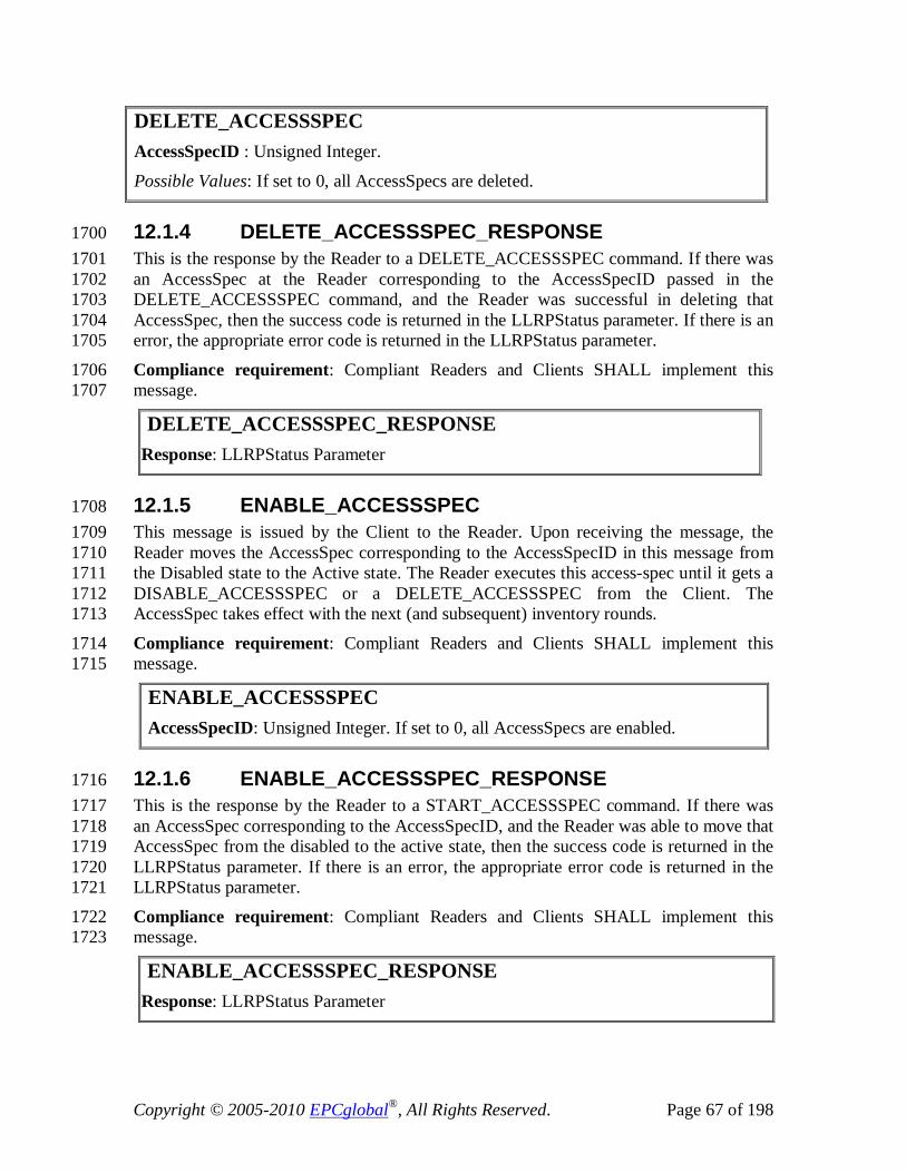
Copyright © 2005-2010 EPCglobal®, All Rights Reserved. Page 67 of 198
DELETE_ACCESSSPEC AccessSpecID : Unsigned Integer.
Possible Values: If set to 0, all AccessSpecs are deleted.
12.1.4 DELETE_ACCESSSPEC_RESPONSE 1700 This is the response by the Reader to a DELETE_ACCESSSPEC command. If there was 1701 an AccessSpec at the Reader corresponding to the AccessSpecID passed in the 1702 DELETE_ACCESSSPEC command, and the Reader was successful in deleting that 1703 AccessSpec, then the success code is returned in the LLRPStatus parameter. If there is an 1704 error, the appropriate error code is returned in the LLRPStatus parameter. 1705
Compliance requirement: Compliant Readers and Clients SHALL implement this 1706 message. 1707
DELETE_ACCESSSPEC_RESPONSE Response: LLRPStatus Parameter
12.1.5 ENABLE_ACCESSSPEC 1708 This message is issued by the Client to the Reader. Upon receiving the message, the 1709 Reader moves the AccessSpec corresponding to the AccessSpecID in this message from 1710 the Disabled state to the Active state. The Reader executes this access-spec until it gets a 1711 DISABLE_ACCESSSPEC or a DELETE_ACCESSSPEC from the Client. The 1712 AccessSpec takes effect with the next (and subsequent) inventory rounds. 1713
Compliance requirement: Compliant Readers and Clients SHALL implement this 1714 message. 1715
ENABLE_ACCESSSPEC AccessSpecID: Unsigned Integer. If set to 0, all AccessSpecs are enabled.
12.1.6 ENABLE_ACCESSSPEC_RESPONSE 1716 This is the response by the Reader to a START_ACCESSSPEC command. If there was 1717 an AccessSpec corresponding to the AccessSpecID, and the Reader was able to move that 1718 AccessSpec from the disabled to the active state, then the success code is returned in the 1719 LLRPStatus parameter. If there is an error, the appropriate error code is returned in the 1720 LLRPStatus parameter. 1721
Compliance requirement: Compliant Readers and Clients SHALL implement this 1722 message. 1723
ENABLE_ACCESSSPEC_RESPONSE Response: LLRPStatus Parameter

Copyright © 2005-2010 EPCglobal®, All Rights Reserved. Page 68 of 198
12.1.7 DISABLE_ACCESSSPEC 1724 This message is issued by the Client to the Reader. Upon receiving the message, the 1725 Reader stops the execution of the AccessSpec corresponding to AccessSpecID in this 1726 message. This basically moves the AccessSpec’s state to Disabled. This message does not 1727 delete the AccessSpec. The AccessSpec will stop taking effect from the next inventory 1728 round. 1729 Compliance requirement: Compliant Readers and Clients SHALL implement this 1730 message. 1731
DISABLE_ACCESSSPEC AccessSpecID: Unsigned Integer. If set to 0, all AccessSpecs are disabled.
12.1.8 DISABLE_ACCESSSPEC_RESPONSE 1732 This is the response by the Reader to a STOP_ACCESSSPEC command. If the Reader 1733 was currently executing the AccessSpec corresponding to the AccessSpecID, and the 1734 Reader was able to disable that AccessSpec, then the success code is returned in the 1735 LLRPStatus parameter. If there is an error, the appropriate error code is returned in the 1736 LLRPStatus parameter. 1737 Compliance requirement: Compliant Readers and Clients SHALL implement this 1738 message. 1739
DISABLE_ACCESSSPEC_RESPONSE Response: LLRPStatus Parameter
12.1.9 GET_ACCESSSPECS 1740 This is the request from the Client to the Reader to retrieve all the AccessSpecs that have 1741 been configured at the Reader. 1742
Compliance requirement: Compliant Readers and Clients SHALL implement this 1743 message. 1744
GET_ACCESSSPECS
12.1.10 GET_ACCESSSPECS_RESPONSE 1745 This is the response by the Reader to a GET_ACCESSSPECS command. If there are no 1746 AccessSpecs configured at the Reader, the response is just the LLRPStatus parameter 1747 with the success code. Else, a list of <AccessSpecID, AccessSpec parameter> is returned 1748 by the Reader, along with the LLRPStatus parameter containing the success code. The 1749 order of the AccessSpecs listed in the message is normatively the order in which the 1750 AccessSpecs were created at the Reader. 1751 Compliance requirement: Compliant Readers and Clients SHALL implement this 1752 message. 1753
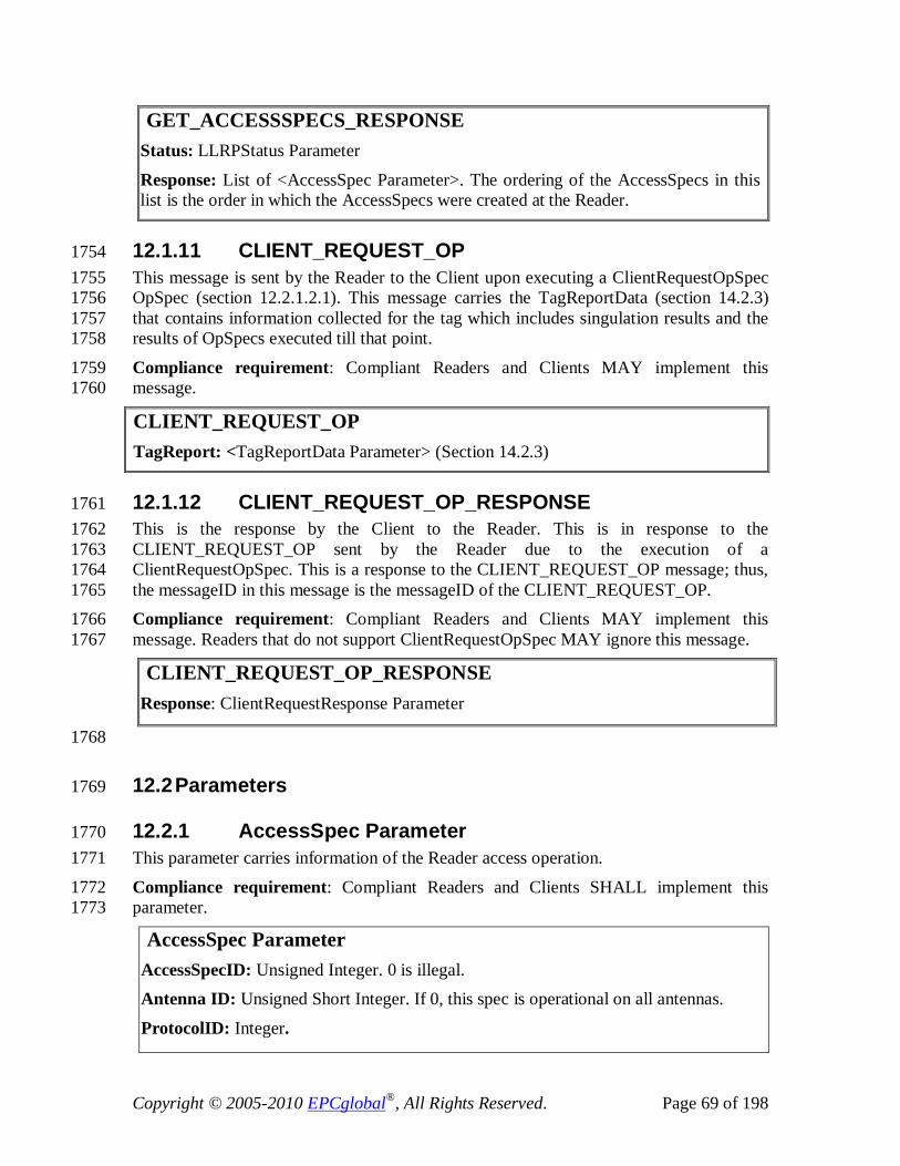
Copyright © 2005-2010 EPCglobal®, All Rights Reserved. Page 69 of 198
GET_ACCESSSPECS_RESPONSE Status: LLRPStatus Parameter
Response: List of <AccessSpec Parameter>. The ordering of the AccessSpecs in this list is the order in which the AccessSpecs were created at the Reader.
12.1.11 CLIENT_REQUEST_OP 1754 This message is sent by the Reader to the Client upon executing a ClientRequestOpSpec 1755 OpSpec (section 12.2.1.2.1). This message carries the TagReportData (section 14.2.3) 1756 that contains information collected for the tag which includes singulation results and the 1757 results of OpSpecs executed till that point. 1758
Compliance requirement: Compliant Readers and Clients MAY implement this 1759 message. 1760
CLIENT_REQUEST_OP TagReport: <TagReportData Parameter> (Section 14.2.3)
12.1.12 CLIENT_REQUEST_OP_RESPONSE 1761 This is the response by the Client to the Reader. This is in response to the 1762 CLIENT_REQUEST_OP sent by the Reader due to the execution of a 1763 ClientRequestOpSpec. This is a response to the CLIENT_REQUEST_OP message; thus, 1764 the messageID in this message is the messageID of the CLIENT_REQUEST_OP. 1765 Compliance requirement: Compliant Readers and Clients MAY implement this 1766 message. Readers that do not support ClientRequestOpSpec MAY ignore this message. 1767
CLIENT_REQUEST_OP_RESPONSE Response: ClientRequestResponse Parameter
1768
12.2 Parameters 1769
12.2.1 AccessSpec Parameter 1770 This parameter carries information of the Reader access operation. 1771
Compliance requirement: Compliant Readers and Clients SHALL implement this 1772 parameter. 1773
AccessSpec Parameter AccessSpecID: Unsigned Integer. 0 is illegal. Antenna ID: Unsigned Short Integer. If 0, this spec is operational on all antennas.
ProtocolID: Integer.

Copyright © 2005-2010 EPCglobal®, All Rights Reserved. Page 70 of 198
Possible Values: Enumeration based on Table 4.
CurrentState: Boolean. This is the current state of the AccessSpec. false = Disabled, true = Active.
ROSpecID: Unsigned Integer. If 0, this spec is operational for all ROSpecs. AccessSpecStopTrigger: AccessSpecStopTrigger Parameter
Access Command Operation: AccessCommand Parameter AccessReportSpec: AccessReportSpec Parameter [Optional]
Custom Extension Point List: List of <custom Parameter> [Optional]
12.2.1.1 AccessSpecStopTrigger Parameter 1774 Compliance requirement: Compliant Readers and Clients SHALL implement this 1775 parameter. 1776
AccessSpecStopTrigger Parameter AccessSpecStopTriggerType: Integer
Possible Values: Value Definition ----- ---------- 0 Null - No stop trigger defined. 1 Operation count OperationCountValue: Unsigned Short Integer. A count to indicate the number of times this Spec is executed before it is deleted. If set to 0, this is equivalent to no stop trigger defined.
12.2.1.2 AccessCommand Parameter 1777 This parameter defines the air protocol access-specific settings. It contains a TagSpec and 1778 an OpSpec Parameter. The TagSpec specifies the tag filters in terms of air protocol 1779 specific memory capabilities (e.g., memory banks, pointer and length). The OpSpec 1780 specifies all the details of the operations required for the air protocol specific access 1781 operation commands. 1782 Compliance requirement: Compliant Readers and Clients SHALL implement this 1783 parameter. 1784
AccessCommand Parameter TagSpec: LLRP Parameter
Possible Values: Each air protocol’s TagSpec parameter is expressed as a different LLRP Parameter. The air protocol specific TagSpec LLRP Parameters are defined in section 16.1. This field carries a single TagSpec parameter corresponding to the air protocol referenced by the ProtocolID in the AccessSpec Parameter.
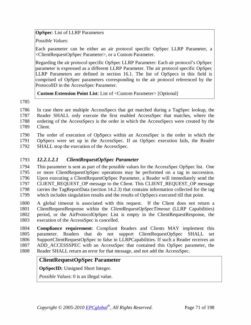
Copyright © 2005-2010 EPCglobal®, All Rights Reserved. Page 71 of 198
OpSpec: List of LLRP Parameters
Possible Values: Each parameter can be either an air protocol specific OpSpec LLRP Parameter, a <ClientRequestOpSpec Parameter>, or a Custom Parameter. Regarding the air protocol specific OpSpec LLRP Parameter: Each air protocol’s OpSpec parameter is expressed as a different LLRP Parameter. The air protocol specific OpSpec LLRP Parameters are defined in section 16.1. The list of OpSpecs in this field is comprised of OpSpec parameters corresponding to the air protocol referenced by the ProtocolID in the AccessSpec Parameter.
Custom Extension Point List: List of <Custom Parameter> [Optional]
1785
In case there are multiple AccessSpecs that get matched during a TagSpec lookup, the 1786 Reader SHALL only execute the first enabled AccessSpec that matches, where the 1787 ordering of the AccessSpecs is the order in which the AccessSpecs were created by the 1788 Client. 1789
The order of execution of OpSpecs within an AccessSpec is the order in which the 1790 OpSpecs were set up in the AccessSpec. If an OpSpec execution fails, the Reader 1791 SHALL stop the execution of the AccessSpec. 1792
12.2.1.2.1 ClientRequestOpSpec Parameter 1793 This parameter is sent as part of the possible values for the AccessSpec OpSpec list. One 1794 or more ClientRequestOpSpec operations may be performed on a tag in succession. 1795 Upon executing a ClientRequestOpSpec Parameter, a Reader will immediately send the 1796 CLIENT_REQUEST_OP message to the Client. This CLIENT_REQUEST_OP message 1797 carries the TagReportData (section 14.2.3) that contains information collected for the tag 1798 which includes singulation results and the results of OpSpecs executed till that point. 1799
A global timeout is associated with this request. If the Client does not return a 1800 ClientRequestResponse within the ClientRequestOpSpecTimeout (LLRP Capabilities) 1801 period, or the AirProtocolOpSpec List is empty in the ClientRequestResponse, the 1802 execution of the AccessSpec is cancelled. 1803
Compliance requirement: Compliant Readers and Clients MAY implement this 1804 parameter. Readers that do not support ClientRequestOpSpec SHALL set 1805 SupportClientRequestOpSpec to false in LLRPCapabilities. If such a Reader receives an 1806 ADD_ACCESSSPEC with an AccessSpec that contained this OpSpec parameter, the 1807 Reader SHALL return an error for that message, and not add the AccessSpec. 1808
ClientRequestOpSpec Parameter OpSpecID: Unsigned Short Integer.
Possible Values: 0 is an illegal value.
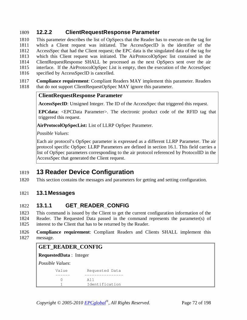
Copyright © 2005-2010 EPCglobal®, All Rights Reserved. Page 72 of 198
12.2.2 ClientRequestResponse Parameter 1809 This parameter describes the list of OpSpecs that the Reader has to execute on the tag for 1810 which a Client request was initiated. The AccessSpecID is the identifier of the 1811 AccessSpec that had the Client request; the EPC data is the singulated data of the tag for 1812 which this Client request was initiated. The AirProtocolOpSpec list contained in the 1813 ClientRequestResponse SHALL be processed as the next OpSpecs sent over the air 1814 interface. If the AirProtocolOpSpec List is empty, then the execution of the AccessSpec 1815 specified by AccessSpecID is cancelled. 1816 Compliance requirement: Compliant Readers MAY implement this parameter. Readers 1817 that do not support ClientRequestOpSpec MAY ignore this parameter. 1818
ClientRequestResponse Parameter AccessSpecID: Unsigned Integer. The ID of the AccessSpec that triggered this request.
EPCdata: <EPCData Parameter>. The electronic product code of the RFID tag that triggered this request.
AirProtocolOpSpecList: List of LLRP OpSpec Parameter. Possible Values:
Each air protocol’s OpSpec parameter is expressed as a different LLRP Parameter. The air protocol specific OpSpec LLRP Parameters are defined in section 16.1. This field carries a list of OpSpec parameters corresponding to the air protocol referenced by ProtocolID in the AccessSpec that generated the Client request.
13 Reader Device Configuration 1819 This section contains the messages and parameters for getting and setting configuration. 1820
13.1 Messages 1821
13.1.1 GET_READER_CONFIG 1822 This command is issued by the Client to get the current configuration information of the 1823 Reader. The Requested Data passed in the command represents the parameter(s) of 1824 interest to the Client that has to be returned by the Reader. 1825 Compliance requirement: Compliant Readers and Clients SHALL implement this 1826 message. 1827
GET_READER_CONFIG RequestedData : Integer
Possible Values: Value Requested Data ------ ---------------- 0 All 1 Identification

Copyright © 2005-2010 EPCglobal®, All Rights Reserved. Page 73 of 198
2 AntennaProperties 3 AntennaConfiguration 4 ROReportSpec 5 ReaderEventNotificationSpec 6 AccessReportSpec 7 LLRPConfigurationStateValue 8 KeepaliveSpec 9 GPIPortCurrentState 10 GPOWriteData 11 EventsAndReports AntennaID: Unsigned Short Integer. This field is ignored when RequestedData != 0 or 2 or 3. If the AntennaID is 0, get antenna information (AntennaProperties, AntennaConfiguration) for all antennas.
GPIPortNum: Unsigned Short Integer. This field is ignored when RequestedData != 0 or 9. If the GPIPortNum is 0, get GPI port current state for all GPI ports.
GPOPortNum: Unsigned Short Integer. This field is ignored when RequestedData != 0 or 10. If the GPOPortNum is 0, get GPO port current state for all GPO ports.
Custom Extension Point List: List of <custom Parameter> [Optional]
13.1.2 GET_READER_CONFIG_RESPONSE 1828 This is the response by the Reader to the GET_READER_CONFIG message. The 1829 response is the LLRPStatus Parameter and the list of configuration parameters based on 1830 the RequestedData in GET_READER_CONFIG. If the GET_READER_CONFIG 1831 message did not have any errors, the success code is returned in the LLRPStatus 1832 parameter, and in addition the requested configuration parameters are returned. If there is 1833 an error, the appropriate error code is returned in the LLRPStatus parameter. The 1834 response contains at most one instance of each configuration parameter except for two 1835 cases, which are as follows: 1836
• If RequestedData is 0, 2 or 3, and AntennaID is set to 0 in the 1837 GET_READER_CONFIG message, the Reader SHALL return one instance of 1838 AntennaProperties Parameter or AntennaConfiguration Parameter per requested 1839 antenna. 1840
• If RequestedData is 0 or 9 (10), and GPIPortNum (GPOPortNum) is set to 0 in the 1841 GET_READER_CONFIG message, and, if the Reader supports GPI (GPO), the 1842 Reader SHALL return one instance of GPIPortCurrentState (GPOWriteData) 1843 Parameter per requested GPI Port (GPO Port). 1844
Compliance requirement: Compliant Readers and Clients SHALL implement this 1845 message. 1846

Copyright © 2005-2010 EPCglobal®, All Rights Reserved. Page 74 of 198
13.1.3 SET_READER_CONFIG 1847 This command is issued by the Client to the Reader. This command sets the Reader 1848 configuration using the parameters specified in this command. Values passed by the 1849 SET_READER_CONFIG SHALL apply for the duration of the LLRP connection, or 1850 until the values are changed by additional SET_READER_CONFIG messages. 1851 For example, ROReportSpec defines the reporting of ROReport format and trigger for a 1852 ROSpec. ROReportSpec sent as part of SET_READER_CONFIG becomes the default 1853 ROReportSpec for the Reader. A ROReportSpec sent as part of ROSpec in the 1854 ADD_ROSPEC command overrides the default value for that ROSpec. However, in 1855 cases where there is no ROReportSpec specified in a ROSpec sent as part of 1856 ADD_ROSPEC, that particular ROSpec inherits the default ROReportSpec. 1857 The data field ResetToFactoryDefault informs the Reader to set all configurable values to 1858 factory defaults before applying the remaining parameters. 1859 Compliance requirement: Compliant Readers and Clients SHALL implement this 1860 message. 1861
GET_READER_CONFIG_RESPONSE Status: LLRPStatus Parameter Response Data: Set of LLRP Parameters.
Possible Values: The possible members are zero or more of {< LLRPConfigurationStateValue Parameter>,
<ReaderEventNotificationSpec Parameter>, <Antenna Properties Parameter>,
<Antenna Configuration Parameter>, <ROReportSpec Parameter>,
<AccessReportSpec Parameter>, <Identification Parameter>,
<KeepaliveSpec Parameter>, <GPIPortCurrentState Parameter>,
<GPOWriteData Parameter>, <EventsAndReports Parameter>
} Custom Extension Point List: List of <custom Parameter> [Optional]

Copyright © 2005-2010 EPCglobal®, All Rights Reserved. Page 75 of 198
13.1.4 SET_READER_CONFIG_RESPONSE 1862 This is the response by the Reader to a SET_READER_CONFIG command. If all the 1863 parameters specified in the SET_READER_CONFIG command are successfully set, then 1864 the success code is returned in the LLRPStatus parameter. If there is an error, the 1865 appropriate error code is returned in the LLRPStatus parameter. 1866 Compliance requirement: Compliant Readers and Clients SHALL implement this 1867 message. 1868
SET_READER_CONFIG_RESPONSE Response: < LLRPStatus Parameter>
13.1.5 CLOSE_CONNECTION 1869 This command is issued by the Client to the Reader. This command instructs the Reader 1870 to gracefully close its connection with the Client. Under normal operating conditions, a 1871 Client SHALL attempt to send this command before closing an LLRP connection. A 1872 Client should wait briefly for the Reader to respond with a 1873 CLOSE_CONNECTION_RESPONSE. 1874 Upon receipt of this command, the Reader SHALL respond with the 1875 CLOSE_CONNECTION_REPONSE message and it should then attempt to close the 1876 connection between the Reader and Client. 1877
SET_READER_CONFIG ResetToFactoryDefault: Boolean. If true, the Reader will set all configurable values to factory defaults before applying the remaining parameters. Configuration Data: Set of LLRP Parameters
Possible Values: The possible members of the set are {<ReaderEventNotificationSpec Parameter>,
<Antenna Properties Parameter>, <Antenna Configuration Parameter>,
<ROReportSpec Parameter>, <AccessReportSpec Parameter>,
<KeepaliveSpec Parameter>, <GPOWriteData Parameter>,
<GPIPortCurrentState Parameter>, <EventsAndReports Parameter>}
Custom Extension Point List: List of <custom Parameter> [Optional]

Copyright © 2005-2010 EPCglobal®, All Rights Reserved. Page 76 of 198
Having executed a CLOSE_CONNECTION command, a Reader MAY persist its 1878 configuration state as defined by the ReaderConfigurationStateValue parameter specified 1879 in section 13.2.1. 1880 Compliance requirement: Compliant Readers and Clients SHALL implement this 1881 message. 1882
CLOSE_CONNECTION
13.1.6 CLOSE_CONNECTION_RESPONSE 1883 This is the response by the Reader to a CLOSE_CONNECTON command from the 1884 Client. Upon receiving a CLOSE_CONNECTION command, the Reader SHALL 1885 attempt to send this response to the Client. After attempting to send this response, the 1886 Reader SHALL close its connection with the Client. 1887
Compliance requirement: Compliant Readers and Clients SHALL implement this 1888 message. 1889
CLOSE_CONNECTION_RESPONSE Status: <LLRPStatus Parameter>
1890
13.2 Parameters 1891
13.2.1 LLRPConfigurationStateValue Parameter 1892 This parameter, LLRPConfigurationStateValue, is a 32-bit value which represents a 1893 Reader’s entire LLRP configuration state including: LLRP configuration parameters, 1894 vendor extension configuration parameters, ROSpecs, and AccessSpecs. A Reader 1895 SHALL change this value only: 1896
• Upon successful execution of any of the following messages: 1897 o ADD_ROSPEC 1898
o DELETE_ROSPEC 1899 o ADD_ACCESSSPEC 1900
o DELETE_ACCESSSPEC 1901 o SET_READER_CONFIG 1902
o Any CUSTOM_MESSAGE command that alters the reader’s internal 1903 configuration. 1904
• Upon an automatically deleted AccessSpec due to completion of 1905 OperationCountValue number of operations (Section 12.2.1.1). 1906
A Reader SHALL not change this value when the CurrentState of a ROSpec or 1907 AccessSpec changes. 1908

Copyright © 2005-2010 EPCglobal®, All Rights Reserved. Page 77 of 198
The mechanism used to compute the LLRP configuration state value is implementation 1909 dependent. However, a good implementation will insure that there’s a high probability 1910 that the value will change when the Reader’s configuration state changes. 1911 It is expected that a Client will configure the Reader and then request the Reader’s 1912 configuration state value. The Client will then save this state value. If this value does not 1913 change between two requests for it, then a Client may assume that the above components 1914 of the LLRP configuration have also not changed. 1915 1916
Compliance requirement: Compliant Readers and Clients SHALL implement this 1917 parameter. When requested by a Client, the Reader SHALL compute a state value based 1918 upon the Reader’s current configuration state. Upon each request, the Reader SHALL 1919 return the same state value provided a Client has not altered the Reader’s configuration 1920 state between requests. Aside from this requirement, the computation of the state value is 1921 implementation dependent. 1922
LLRPConfigurationStateValue Parameter LLRPConfigurationStateValue: Unsigned Integer
13.2.2 Identification Parameter 1923 This parameter carries an identification parameter that is unique within the local 1924 administration domain. The identifier could be the Reader MAC address or EPC. The 1925 IDType defines the type of the identification value contained in this Parameter. 1926
Compliance requirement: Compliant Readers and Clients SHALL implement this 1927 parameter. 1928
Identification Parameter IDType: Integer Possible Values: IDType ID ------ -- 0 MAC address 1 EPC
Reader ID: Byte array. If IDType=0, the MAC address SHALL be encoded as EUI-64.[EUI64]
13.2.3 GPOWriteData Parameter 1929 This parameter carries the data pertinent to perform the write to a general purpose output 1930 port. 1931
Compliance requirement: Compliant Readers and Clients MAY implement this 1932 parameter. Readers that do not support GPOs SHALL set NumGPOs in the 1933 GPIOCapabilities to zero. If such a Reader receives a SET_READER_CONFIG with 1934
Copyright © 2005-2010 EPCglobal®, All Rights Reserved. Page 78 of 198
GPOWriteData Parameter, the Reader SHALL return an error message and not process 1935 any of the parameters in that message. 1936
GPOWriteData Parameter GPO Port Number : Unsigned Short Integer. 0 is invalid.
GPO Data: Boolean. The state to output on the specified GPO port.
13.2.4 KeepaliveSpec Parameter 1937 This parameter carries the specification for the keepalive message generation by the 1938 Reader. This includes the definition of the periodic trigger to send the keepalive message. 1939
Compliance requirement: Compliant Readers and Clients SHALL implement this 1940 parameter. 1941
KeepaliveSpec Parameter KeepaliveTriggerType: Integer Possible Values: Value Definition ----- ---------- 0 Null – No keepalives SHALL be sent by the Reader 1 Periodic PeriodicTriggerValue: Integer. Time interval in milliseconds. This field is ignored when KeepaliveTriggerType is not 1.
13.2.5 AntennaProperties Parameter 1942 This parameter carries a single antenna's properties. The properties include the gain and 1943 the connectivity status of the antenna.The antenna gain is the composite gain and includes 1944 the loss of the associated cable from the Reader to the antenna. The gain is represented in 1945 dBi*100 to allow fractional dBi representation. 1946 Compliance requirement: Compliant Readers and Clients MAY implement this 1947 parameter. 1948
AntennaProperties Parameter AntennaID: Unsigned Short Integer Possible Values:
1 to N, where N is the maximum number of antennas supported by the device. AntennaGain: Signed short integer. The gain of the antenna in dBI*100 (dB relative to Isotropic) to allow for fractional dBi representation.
AntennaConnected: Boolean. False = not connected, True = connected.

Copyright © 2005-2010 EPCglobal®, All Rights Reserved. Page 79 of 198
13.2.6 AntennaConfiguration Parameter 1949 This parameter carries a single antenna's configuration and it specifies the default values 1950 for the parameter set that are passed in this parameter block. The scope of the default 1951 values is the antenna. The default values are used for parameters during an operation on 1952 this antenna if the parameter was unspecified in the spec that describes the operation. 1953
Compliance requirement: Compliant Readers and Clients SHALL implement this 1954 parameter. 1955
AntennaConfiguration Parameter Antenna ID: Unsigned Short Integer. If set to zero, this configuration applies to all the antennas.
RFReceiverSettings: <RFReceiver Parameter> [Optional] RFTransmitterSettings: <RFTransmitter Parameter> [Optional]
AirProtocolInventoryCommandSettings: List of LLRP parameters. [Optional] Possible Values:
Each air protocol’s inventory command parameter is expressed as a different LLRP Parameter. The air protocol specific inventory command LLRP Parameters are defined in section 16.1. This field is a list of inventory command LLRP Parameters, one per air protocol, that the Client would like to use as the default inventory command setting for inventory operations using the air protocol on this antenna. Custom Extension Point List: List of <custom Parameter> [Optional]
13.2.6.1 RFReceiver Parameter 1956 This Parameter carries the RF receiver information. The Receiver Sensitivity defines the 1957 sensitivity setting at the receiver. The value is the index into the ReceiveSensitivityTable 1958 (section 10.2.1.1). 1959 Compliance requirement: Compliant Readers and Clients SHALL implement this 1960 parameter. 1961
RFReceiver Parameter ReceiverSensitivity: Unsigned Short Integer - an index into the ReceiveSensitivity Table (section 10.2.1.1)
13.2.6.2 RFTransmitter Parameter 1962 This Parameter carries the RF transmitter information. The Transmit Power defines the 1963 transmit power for the antenna expressed as an index into the TransmitPowerTable 1964 (section 10.2.4.1.1). The HopTableID is the index of the frequency hop table to be used 1965 by the Reader (section 10.2.4.1.2.1) and is used when operating in frequency-hopping 1966 regulatory regions. This field is ignored in non-frequency-hopping regulatory regions. 1967 The ChannelIndex is the one-based channel index in the FixedFrequencyTable to use 1968 during transmission (section 10.2.4.1.2.2) and is used when operating in non-frequency-1969

Copyright © 2005-2010 EPCglobal®, All Rights Reserved. Page 80 of 198
hopping regulatory regions. This field is ignored in frequency-hopping regulatory 1970 regions. 1971 Compliance requirement: Compliant Readers and Clients SHALL implement this 1972 parameter. 1973
RFTransmitter Parameter Transmit Power: Unsigned Short Integer - an index into the Transmit Power table. HopTableID : Unsigned Short Integer
ChannelIndex : Unsigned Short Integer. This is the index of the frequency to use.
13.2.6.3 GPIPortCurrentState Parameter 1974 This Parameter carries the current configuration and state of a single GPI port. In a 1975 SET_READER_CONFIG message, this parameter is used to enable or disable the GPI 1976 port using the GPIConfig field; the GPIState field is ignored by the reader. In a 1977 GET_READER_CONFIG message, this parameter reports both the configuration and 1978 state of the GPI port. 1979 1980 When a ROSpec or AISpec is configured on a GPI-capable reader with GPI start and/or 1981 stop triggers, those GPIs must be enabled by the client with a SET_READER_CONFIG 1982 message for the triggers to function. 1983 1984 Compliance requirement: Compliant Readers and Clients MAY implement this 1985 parameter. Readers that do not support GPIs SHALL set NumGPIs in the 1986 GPIOCapabilities to zero. If such a Reader receives a GET_READER_CONFIG with a 1987 GPIPortCurrentState Parameter, the Reader SHALL return an error message and not 1988 process any of the parameters in that message. 1989
GPIPortCurrentState Parameter GPIPortNum: Unsigned Short Integer. Zero is illegal.
GPIConfig : Boolean (0 for disabled, 1 for enabled) GPIState : Integer (ignored in SET_READER_CONFIG messages)
Possible Values: Value Definition ----- ---------- 0 GPI state is low 1 GPI state is high 2 GPI state is unknown
13.2.6.4 EventsAndReports Parameter 1990 This parameter controls the behavior of the Reader when a new LLRP connection is 1991 established. In a SET_READER_CONFIG message, this parameter is used to enable or 1992 disable the holding of events and reports upon connection using the 1993 HoldEventsAndReportsUponReconnect field. In a GET_READER_CONFIG message, 1994 this parameter reports the current configuration. If the 1995
Copyright © 2005-2010 EPCglobal®, All Rights Reserved. Page 81 of 198
HoldEventsAndReportsUponReconnect is true, the reader will not deliver any reports or 1996 events (except the ConnectionAttemptEvent) to the Client until the Client issues an 1997 ENABLE_EVENTS_AND_REPORTS message. Once the 1998 ENABLE_EVENTS_AND_REPORTS message is received the reader ceases its hold on 1999 events and reports for the duration of the connection. 2000 2001 Compliance requirement: Compliant Readers and Clients MAY implement this 2002 parameter. 2003
EventsAndReports Parameter HoldEventsAndReportsUponReconnect: Boolean. (False does not hold reports and events, True holds reports and events)
14 Reports, Notifications and Keepalives 2004 This section describes the messages and parameters used in reports, event notifications 2005 and keepalives that are generated by the Reader and sent to the Client. 2006 The Reader SHALL send reports only when 2007
• A reporting trigger (ROReportTrigger or AccessReportTrigger) generates a report 2008 while a connection is open, or 2009
• In response to an explicit Client request (GET_REPORT or 2010 ENABLE_EVENTS_AND_REPORTS), or 2011
• A notification event occurs and the event is enabled. 2012 The triggers may be specified per ROSpec and AccessSpec using ROReportSpec and 2013 AccessReportSpec parameters. In a report, the Reader SHALL send new data (results of 2014 ROSpecs and/or AccessSpecs) acquired since the last report message. The tag report data 2015 generated by the AccessReport trigger SHALL NOT duplicate the tag report data 2016 generated by the ROReportTrigger, and vice-versa. 2017
14.1 Messages 2018
14.1.1 GET_REPORT 2019 This message is issued by the Client to the Reader to get the tag reports. In response to 2020 this message, the Reader SHALL return tag reports accumulated. If no reports are 2021 available to send as a response to a GET_REPORT message, the Reader MAY return an 2022 empty RO_ACCESS_REPORT message. 2023
Compliance requirement: Compliant Readers and Clients SHALL implement this 2024 message. 2025
GET_REPORT

Copyright © 2005-2010 EPCglobal®, All Rights Reserved. Page 82 of 198
14.1.2 RO_ACCESS_REPORT 2026 This message is issued by the Reader to the Client, and it contains the results of the RO 2027 and Access operations. The ROReportSpec and AccessReportSpec parameters define the 2028 contents and triggers for this message. 2029 Compliance requirement: Compliant Readers and Clients SHALL implement this 2030 message. 2031
RO_ACCESS_REPORT InventoryAccessReportData: List of <TagReportData Parameter> [Optional]
RFSurveyReportData: List of <RFSurveyReportData Parameter> [Optional] Custom Extension Point List: List of <custom Parameter> [Optional]
14.1.3 KEEPALIVE 2032 This message is issued by the Reader to the Client. This message can be used by the 2033 Client to monitor the LLRP-layer connectivity with the Reader. The Client configures the 2034 trigger at the Reader to send the Keepalive message. The configuration is done using the 2035 KeepaliveSpec parameter (section 13.2.4). 2036
Compliance requirement: Compliant Readers and Clients SHALL implement this 2037 message. 2038
KEEPALIVE
14.1.4 KEEPALIVE_ACK 2039 A Client SHALL generate a KEEPALIVE_ACK in response to each KEEPALIVE 2040 received by the Reader. If the Reader fails to receive multiple consecutive 2041 KEEPALIVE_ACK responses to its KEEPALIVE requests, the Reader MAY assume the 2042 client connection is defunct and can be closed. 2043
Compliance requirement: Compliant Readers and Clients SHALL implement this 2044 message. 2045
KEEPALIVE_ACK
14.1.5 READER_EVENT_NOTIFICATION 2046 This message is issued by the Reader to the Client whenever an event that the Client 2047 subscribed to occurs. The pertinent event data is conveyed using the 2048 ReaderEventNotificationData parameter. 2049 Compliance requirement: Compliant Readers and Clients SHALL implement this 2050 message. 2051

Copyright © 2005-2010 EPCglobal®, All Rights Reserved. Page 83 of 198
READER_EVENT_NOTIFICATION ReaderEventNotificationData: ReaderEventNotificationData Parameter
2052
14.1.6 ENABLE_EVENTS_AND_REPORTS 2053 This message can be issued by the Client to the Reader after a LLRP connection is 2054 established. The Client uses this message to inform the Reader that it can remove its hold 2055 on event and report messages. Readers that are configured to hold events and reports on 2056 reconnection (See Section 13.2.6.4) respond to this message by returning the tag reports 2057 accumulated (same way they respond to GET_REPORT (See Section 13.1.1)). 2058
Compliance requirement: Compliant Readers and Clients MAY implement this 2059 message. 2060
ENABLE_EVENTS_AND_REPORTS
2061
14.2 Parameters 2062
14.2.1 ROReportSpec Parameter 2063 This Parameter carries the Reader inventory and RF survey reporting definition for the 2064 antenna. This parameter describes the contents of the report sent by the Reader and 2065 defines the events that cause the report to be sent. 2066 The ROReportTrigger field defines the events that cause the report to be sent. 2067
The TagReportContentSelector parameter defines the desired contents of the report. The 2068 ROReportTrigger defines the event that causes the report to be sent by the Reader to the 2069 Client. 2070 See section 14.2.6.1 for details about the order that reports are to be sent with respect to 2071 Reader event notifications. 2072 Custom extensions to this parameter are intended to specify summary data to be reported 2073 as an extension to the RO_ACCESS_REPORT message (see section 14.1.2). 2074 Compliance requirement: Compliant Readers and Clients SHALL implement this 2075 parameter. 2076
ROReportSpec Parameter ROReportTrigger: Integer
Possible Values: Value Definition ----- ---------- 0 None

Copyright © 2005-2010 EPCglobal®, All Rights Reserved. Page 84 of 198
1 (Upon N TagReportData Parameters or End of AISpec) Or (End of RFSurveySpec) - N=0 is unlimited. 2 Upon N TagReportData Parameters or End of ROSpec - N=0 is unlimited. 3 Upon N seconds or (End of AISpec or End of RFSurveySpec) – N=0 is unlimited. 4 Upon N seconds or End of ROSpec – N=0 is unlimited. 5 Upon N milliseconds or (End of AISpec or End of RFSurveySpec) – N=0 is unlimited. 6 Upon N milliseconds or End of ROSpec – N=0 is unlimited. N: Unsigned Short Integer. When ROReportTrigger = 1 or 2, this is the number of TagReportData parameters present in a report before the report trigger fires. When ROReportTrigger = 3 or 4, this is the number of seconds since the last report was generated before the report trigger fires. When ROReportTrigger = 5 or 6, this is the number of milliseconds since the last report was generated before the report trigger fires. If N = 0, there is no limit on either the number of TagReportData parameters, or the time since the last report was generated. This field SHALL be ignored when ROReportTrigger = 0. ReportContents: <TagReportContentSelector Parameter>
Custom Extension Point List: List of <Custom Parameter> [Optional]
14.2.1.1 TagReportContentSelector Parameter 2077 This parameter is used to configure the contents that are of interest in TagReportData. If 2078 enabled, the field is reported along with the tag data in the TagReportData. 2079
Custom extensions to this parameter are intended to specify data related to each tag that 2080 is to be reported as an extension to the TagReportData parameter (see section 14.2.3). 2081
Compliance requirement: Compliant Readers and Clients SHALL implement this 2082 parameter. 2083
TagReportContentSelector EnableROSpecID: Boolean EnableSpecIndex: Boolean
EnableInventoryParameterSpecID: Boolean EnableAntennaID: Boolean
EnableChannelIndex: Boolean EnablePeakRSSI: Boolean
EnableFirstSeenTimestamp: Boolean EnableLastSeenTimestamp: Boolean
EnableTagSeenCount: Boolean

Copyright © 2005-2010 EPCglobal®, All Rights Reserved. Page 85 of 198
AirProtocolSpecificEPCMemorySelector: LLRP parameter.
Possible Values: Each air protocol’s EPC memory selector parameter is expressed as a different LLRP Parameter. The air protocol specific EPC memory selector LLRP Parameters are defined in section 16.1. This field is the EPC memory selector LLRP Parameter corresponding to the air protocol referenced by the ProtocolID in the ROSpec that the ROReportSpec is part of.
EnableAccessSpecID: Boolean Custom Extension Point List: List of <Custom Parameter> [Optional]
14.2.2 AccessReportSpec Parameter 2084 This parameter sets up the triggers for the Reader to send the access results to the Client. 2085 In addition, the Client can enable or disable reporting of ROSpec details in the access 2086 results. 2087
Compliance requirement: Compliant Readers and Clients SHALL implement this 2088 parameter. 2089
AccessReportSpec AccessReportTrigger: Integer Possible Values: Value Definition ----- ---------- 0 Whenever ROReport is generated for the RO that triggered the execution of this AccessSpec. 1 End of AccessSpec (immediately upon completion of the access operation)
14.2.3 TagReportData Parameter 2090 This report parameter is generated per tag per accumulation scope. The only mandatory 2091 portion of this parameter is the EPCData parameter. If there was an access operation 2092 performed on the tag, the results of the OpSpecs are mandatory in the report. The other 2093 sub-parameters in this report are optional. LLRP provides three ways to make the tag 2094 reporting efficient: 2095
(i) Allow parameters to be enabled or disabled via TagReportContentSelector 2096 (section 14.2.1.1) in TagReportSpec. 2097
(ii) If an optional parameter is enabled, and is absent in the report, the Client 2098 SHALL assume that the value is identical to the last parameter of the same 2099 type received. For example, this allows the Readers to not send a parameter in 2100 the report whose value has not changed since the last time it was sent by the 2101 Reader. 2102
(iii) Allow accumulation of tag reports. See next section for details of 2103 accumulation. 2104

Copyright © 2005-2010 EPCglobal®, All Rights Reserved. Page 86 of 198
Compliance Requirement: Compliant Readers and Clients SHALL implement this 2105 parameter. 2106
TagReportData Parameter EPCData: <EPCData Parameter>
ROSpecID: <ROSpecID Parameter> [Optional] SpecIndex: <SpecIndex Parameter> [Optional]
InventoryParameterSpecID: <InventoryParameterSpecID Parameter> [Optional] AntennaID: <AntennaID Parameter> [Optional]
PeakRSSI: <PeakRSSI Parameter> [Optional] ChannelIndex: <ChannelIndex Parameter> [Optional]
FirstSeenTimestampUTC: <UTCFirstSeenTimestamp Parameter> [Optional] FirstSeenTimeStampUptime: <UptimeFirstSeenTimestamp Parameter> [Optional]
LastSeenTimestampUTC: <UTCLastSeenTimestamp Parameter> [Optional] LastSeenTimeStampUptime: <UptimeLastSeenTimestamp Parameter> [Optional]
TagSeenCount: <TagSeenCount Parameter> [Optional] AirProtocolTagData: LLRP Parameters (e.g., C1G2EPC-PC, C1G2EPC-CRC) [Optional] Possible Values:
Each air protocol’s AirProtocolTagData parameter is expressed as a different LLRP Parameter. The air protocol specific AirProtocolTagData LLRP Parameters are defined in section 16.1. This field is the AirProtocolTagData LLRP Parameter corresponding to the air protocol referenced by the ProtocolID of the InventoryParameterSpec during whose execution this tag was observed. AccessSpecID: <AccessSpecID Parameter> [Optional]
OpSpecResultList: List of LLRP parameters [Optional] Possible Values of each LLRP Parameter: Air protocol specific OpSpecResult parameter, <ClientRequestOpSpecResult Parameter>, or Custom Parameter. Regarding the air protocol specific OpSpecResult parameter: Each air protocol’s OpSpecResult parameter is expressed as a different LLRP Parameter. The air protocol specific OpSpecResult LLRP Parameters are defined in section 16.1. This field is a list of OpSpecResult LLRP Parameters corresponding to the air protocol referenced by the ProtocolID of the AccessSpec.
Custom Extension Point List: List of <Custom Parameter> [Optional]
14.2.3.1 Accumulation of TagReportData 2107 A Reader MAY accumulate multiple tag reports into a single tag report.. If a Reader 2108 accumulates, the Reader SHALL follow the accumulation rules specified in this section. 2109

Copyright © 2005-2010 EPCglobal®, All Rights Reserved. Page 87 of 198
The following specifies the rules for accumulating multiple tag observations into a single 2110 TagReportData: 2111
• EPCData: 2112 o The Reader SHALL not accumulate tag reports that do not have the same 2113
EPCData value. 2114
• OpSpecResultList: 2115 o The Reader SHALL not accumulate tag reports that do not have the same 2116
value for the OpSpec results in the OpSpecResultList. 2117
• SpecID, SpecIndex, InventoryParameterSpecID, AntennaID, 2118 AirProtocolTagData, AccessSpecID: 2119
o These fields are optional, and their reporting can be enabled by the Client. 2120 If the Client has enabled one or more fields listed above, the Reader 2121 SHALL not accumulate tag reports that do not have the same value for all 2122 the enabled fields. 2123
• FirstSeenTimestamp, LastSeenTimestamp, PeakRSSI, TagSeenCount, 2124 ChannelIndex 2125
o These fields are optional, and their reporting can be enabled by the Client. 2126 If the field is enabled, the Reader sets the value of these fields as follows: 2127 FirstSeenTimestamp: The Reader SHALL set it to the time of the 2128
first observation amongst the tag reports that get accumulated in 2129 the TagReportData. 2130
LastSeenTimestamp: The Reader SHALL set it to the time of the 2131 last observation amongst the tag reports that get accumulated in the 2132 TagReportData. 2133
PeakRSSI: The Reader SHALL set it to the maximum RSSI value 2134 observed amongst the tag reports that get accumulated in the 2135 TagReportData. 2136
ChannelIndex: The Reader MAY set it to the index of the first 2137 channel the tag was seen. 2138
TagSeenCount: The Reader SHALL set it to the number of tag 2139 reports that get accumulated in the TagReportData. 2140
14.2.3.2 EPCData Parameter 2141 This parameter carries the EPC identifier information. 2142 Compliance requirement: Compliant Readers and Clients SHALL implement this 2143 parameter. 2144
EPCData Parameter EPC: Bit array
Copyright © 2005-2010 EPCglobal®, All Rights Reserved. Page 88 of 198
14.2.3.3 ROSpecID Parameter 2145 This parameter carries the ROSpecID information. 2146 Compliance requirement: Compliant Readers and Clients SHALL implement this 2147 parameter. 2148
ROSpecID Parameter ROSpecID: Unsigned Integer
14.2.3.4 SpecIndex Parameter 2149 This parameter carries the SpecIndex information. The SpecIndex indicates the item 2150 within the ROSpec that was being executed at the time the tag was observed. 2151 Compliance requirement: Compliant Readers and Clients SHALL implement this 2152 parameter. 2153
SpecIndex Parameter SpecIndex: Unsigned Short Integer
14.2.3.5 InventoryParameterSpecID Parameter 2154 This parameter carries the InventoryParameterSpecID information. 2155 Compliance requirement: Compliant Readers and Clients SHALL implement this 2156 parameter. 2157
InventoryParameterSpecID Parameter InventoryParameterSpecID: Unsigned Short Integer
14.2.3.6 AntennaID Parameter 2158 This parameter carries the AntennaID information. 2159
Compliance requirement: Compliant Readers and Clients SHALL implement this 2160 parameter. 2161
AntennaID Parameter AntennaID: Unsigned Short Integer
14.2.3.7 PeakRSSI Parameter 2162 This parameter carries the PeakRSSI information. 2163
Compliance requirement: Compliant Readers and Clients SHALL implement this 2164 parameter. 2165
PeakRSSI Parameter PeakRSSI: Signed Integer. The peak received power of the EPC backscatter in dBm.
Possible Values:
Copyright © 2005-2010 EPCglobal®, All Rights Reserved. Page 89 of 198
-128 to +127.
14.2.3.8 ChannelIndex Parameter 2166 This parameter carries the one-based ChannelIndex value. 2167 Compliance requirement: Compliant Readers and Clients SHALL implement this 2168 parameter. 2169
ChannelIndex Parameter ChannelIndex: Unsigned Integer
Possible Values: 1 to 255.
14.2.3.9 FirstSeenTimestampUTC Parameter 2170 This parameter carries the FirstSeenTimestamp information in UTC. 2171
Compliance requirement: Compliant Readers and Clients that have UTC clocks 2172 SHALL implement this parameter. 2173
FirstSeenTimestampUTC Parameter Microseconds: Unsigned long Integer. This is the time elapsed since the Epoch (00:00:00 UTC, January 1, 1970) measured in microseconds.
14.2.3.10 FirstSeenTimestampUptime Parameter 2174 This parameter carries the FirstSeenTimestamp information in Uptime. 2175
Compliance requirement: Compliant Readers and Clients that do not have UTC clocks 2176 SHALL implement this parameter. Compliant Readers and Clients that have UTC clocks 2177 MAY implement this parameter. 2178
FirstSeenTimestampUptime Parameter Microseconds: Unsigned long Integer. This is the time elapsed since boot, measured in microseconds.
14.2.3.11 LastSeenTimestampUTC Parameter 2179 This parameter carries the LastSeenTimestamp information in UTC. 2180
Compliance requirement: Compliant Readers and Clients that have UTC clocks 2181 SHALL implement this parameter. 2182
LastSeenTimestampUTC Parameter Microseconds: Unsigned long Integer. This is the time elapsed since the Epoch (00:00:00 UTC, January 1, 1970) measured in microseconds.
14.2.3.12 LastSeenTimestampUptime Parameter 2183 This parameter carries the LastSeenTimestamp information in Uptime. 2184

Copyright © 2005-2010 EPCglobal®, All Rights Reserved. Page 90 of 198
Compliance requirement: Compliant Readers and Clients that do not have UTC clocks 2185 SHALL implement this parameter. Compliant Readers and Clients that have UTC clocks 2186 MAY implement this parameter. 2187
LastSeenTimestampUptime Parameter Microseconds: Unsigned long Integer. This is the time elapsed since boot, measured in microseconds.
14.2.3.13 TagSeenCount Parameter 2188 This parameter carries the tag seen count information. If TagSeenCount > 65535 for the 2189 report period, the reader SHALL report 65535. 2190
Compliance requirement: Compliant Readers and Clients SHALL implement this 2191 parameter. 2192
TagSeenCount Parameter Count: Unsigned Short Integer
14.2.3.14 ClientRequestOpSpecResult Parameter 2193 Compliance requirement: Compliant Readers and Clients MAY implement this 2194 parameter. 2195
ClientRequestOpSpecResult Parameter OpSpecID: Unsigned Short Integer. 0 is illegal.
14.2.3.15 AccessSpecID Parameter 2196 This parameter carries the AccessSpecID information. 2197
Compliance requirement: Compliant Readers and Clients SHALL implement this 2198 parameter. 2199
AccessSpecID Parameter AccessSpecID: Unsigned Integer
14.2.4 RFSurveyReportData Parameter 2200 This describes the content of the RF Survey Report. 2201 Compliance requirement: Compliant Readers and Clients MAY implement this 2202 parameter. 2203
RFSurveyReportData Parameter ROSpecID: <ROSpecID Parameter> [Optional] SpecIndex: <SpecIndex Parameter> [Optional]
FrequencyPowerLevelList: List of <FrequencyRSSILevelEntry Parameter>
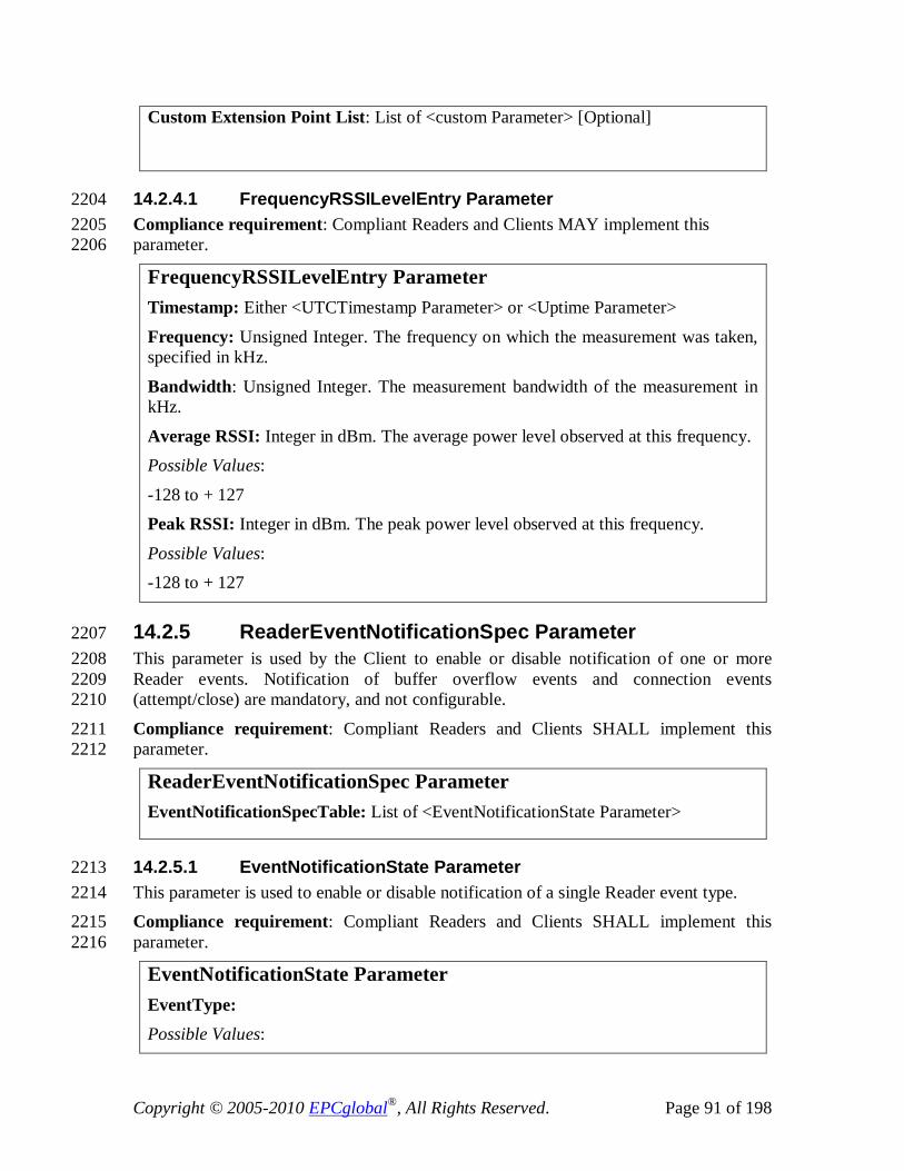
Copyright © 2005-2010 EPCglobal®, All Rights Reserved. Page 91 of 198
Custom Extension Point List: List of <custom Parameter> [Optional]
14.2.4.1 FrequencyRSSILevelEntry Parameter 2204 Compliance requirement: Compliant Readers and Clients MAY implement this 2205 parameter. 2206
FrequencyRSSILevelEntry Parameter Timestamp: Either <UTCTimestamp Parameter> or <Uptime Parameter>
Frequency: Unsigned Integer. The frequency on which the measurement was taken, specified in kHz.
Bandwidth: Unsigned Integer. The measurement bandwidth of the measurement in kHz.
Average RSSI: Integer in dBm. The average power level observed at this frequency. Possible Values:
-128 to + 127 Peak RSSI: Integer in dBm. The peak power level observed at this frequency.
Possible Values: -128 to + 127
14.2.5 ReaderEventNotificationSpec Parameter 2207 This parameter is used by the Client to enable or disable notification of one or more 2208 Reader events. Notification of buffer overflow events and connection events 2209 (attempt/close) are mandatory, and not configurable. 2210
Compliance requirement: Compliant Readers and Clients SHALL implement this 2211 parameter. 2212
ReaderEventNotificationSpec Parameter EventNotificationSpecTable: List of <EventNotificationState Parameter>
14.2.5.1 EventNotificationState Parameter 2213 This parameter is used to enable or disable notification of a single Reader event type. 2214 Compliance requirement: Compliant Readers and Clients SHALL implement this 2215 parameter. 2216
EventNotificationState Parameter EventType: Possible Values:

Copyright © 2005-2010 EPCglobal®, All Rights Reserved. Page 92 of 198
Value Definition ----- ----------
0 Upon hopping to next channel (e.g., in FCC regulatory region)
1 GPI event 2 ROSpec event (start/end/preempt) 3 Report buffer fill warning 4 Reader exception event 5 RFSurvey event (start/end) 6 AISpec event (end) 7 AISpec event (end) with singulation details 8 Antenna event (disconnect/connect) 9 SpecLoop event NotificationState: Boolean; enable = true, disable = false.
14.2.6 ReaderEventNotificationData Parameter 2217 This parameter describes the contents of the event notification sent by the Reader, and 2218 defines the events that cause the notification to be sent. Event notification messages may 2219 be sent by the Reader due to connection establishment/closing event, critical events such 2220 as hopping, fault-detection in a Reader functional block, buffer overflow, due to the 2221 activation of a Reader accessory trigger input (e.g. motion detection), or due to 2222 performance monitoring events such as abnormalities in the RF environment. 2223
Timestamp is the time that the events reported occurred. 2224 Compliance requirement: Compliant Readers and Clients SHALL implement this 2225 parameter. 2226
ReaderEventNotificationData Parameter Timestamp: Either <UTCTimestamp Parameter> or <Uptime Parameter>
Events: List of events. Possible Values: The possible members of the list are
{ <HoppingEventParameter>,
<GPIEvent Parameter>, <ROSpecEvent Parameter>,
<ReportBufferLevelWarningEvent Parameter>, <ReportBufferOverflowErrorEvent Parameter>,
<ReaderExceptionEvent Parameter>, <RFSurveyEvent Parameter>,
<AISpecEvent Parameter>, <AntennaEvent Parameter>,
<ConnectionAttemptEvent Parameter>,

Copyright © 2005-2010 EPCglobal®, All Rights Reserved. Page 93 of 198
<ConnectionCloseEvent Parameter>,
<SpecLoopEvent Parameter> }
Custom Extension Point List: List of <custom Parameter> [optional]
14.2.6.1 Requirements for Ordering of Event Reporting 2227 LLRP assumes a reliable stream transport mechanism. Messages sent through LLRP will 2228 arrive in the order that they were sent over the transport and binding utilized. Status 2229 events within the same message SHALL be ordered chronologically. 2230
Status events delivered by reader event notifications are useful, especially in conjunction 2231 with the tag report data. The following describes the requirements of the reader event 2232 notifications ordering with respect to the ordering of tag reports and Reader Event 2233 Notifications. 2234
The following requirements are made on the ordering of Event Parameters with respect to 2235 each other and to tag report Parameters. These statements apply if the respective status 2236 events and report triggers are enabled. 2237 If the start of an ROSpec is triggered by a GPI, the GPIEvent Parameter SHALL be sent 2238 before the ROSpecEvent Parameter signaling the start of the ROSpec. 2239 If the end of an ROSpec is triggered by a GPI, the GPIEvent Parameter SHALL be sent 2240 before the ROSpecEvent Parameter signaling the end of the ROSpec. 2241 If an ROSpec contains one or more AISpecs, the ROSpecEvent parameter signaling the 2242 end of an ROSpec SHALL be sent after the AISpecEvent Parameter signaling the end of 2243 the last AISpec within that ROSpec. 2244
If one ROSpec pre-empts another ROSpec, the ROSpecEvent parameter signaling the 2245 preemption of the first ROSpec SHALL be sent before the ROSpecEvent parameter 2246 signaling the start of the next ROSpec. 2247 Tag data received during an ROSpec execution SHALL be sent between the 2248 ROSpecEvent parameter signaling the start of the ROSpec and the ROSpecEvent 2249 parameter signaling the end or preemption of the ROSpec if the ROReportTrigger is not 2250 set to ‘None’. 2251 Tag data received during an AISpec execution SHALL be sent before the AISpecEvent 2252 Parameter signaling the end of the AISpec if the ROReportTrigger is not ‘None’ or ‘end 2253 of RO Spec’ 2254
Tag data received during the time on a channel SHALL be sent after the HoppingEvent 2255 parameter that announced this channel and before the next HoppingEvent parameter 2256 when the ROReportTrigger is not ‘None’ and N=1. 2257
14.2.6.2 HoppingEvent Parameter 2258 A Reader reports this event every time it hops frequency. 2259
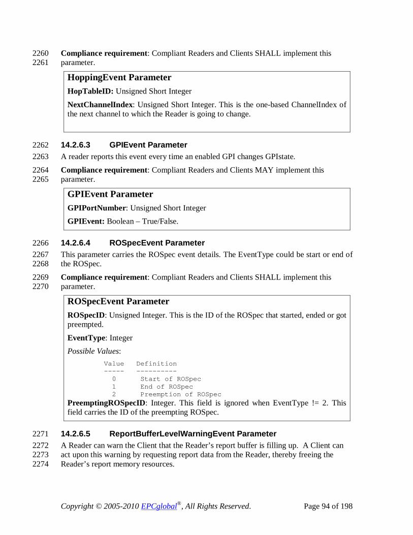
Copyright © 2005-2010 EPCglobal®, All Rights Reserved. Page 94 of 198
Compliance requirement: Compliant Readers and Clients SHALL implement this 2260 parameter. 2261
HoppingEvent Parameter HopTableID: Unsigned Short Integer
NextChannelIndex: Unsigned Short Integer. This is the one-based ChannelIndex of the next channel to which the Reader is going to change.
14.2.6.3 GPIEvent Parameter 2262 A reader reports this event every time an enabled GPI changes GPIstate. 2263
Compliance requirement: Compliant Readers and Clients MAY implement this 2264 parameter. 2265
GPIEvent Parameter GPIPortNumber: Unsigned Short Integer GPIEvent: Boolean – True/False.
14.2.6.4 ROSpecEvent Parameter 2266 This parameter carries the ROSpec event details. The EventType could be start or end of 2267 the ROSpec. 2268
Compliance requirement: Compliant Readers and Clients SHALL implement this 2269 parameter. 2270
ROSpecEvent Parameter ROSpecID: Unsigned Integer. This is the ID of the ROSpec that started, ended or got preempted.
EventType: Integer Possible Values: Value Definition ----- ----------
0 Start of ROSpec 1 End of ROSpec 2 Preemption of ROSpec PreemptingROSpecID: Integer. This field is ignored when EventType != 2. This field carries the ID of the preempting ROSpec.
14.2.6.5 ReportBufferLevelWarningEvent Parameter 2271 A Reader can warn the Client that the Reader’s report buffer is filling up. A Client can 2272 act upon this warning by requesting report data from the Reader, thereby freeing the 2273 Reader’s report memory resources. 2274

Copyright © 2005-2010 EPCglobal®, All Rights Reserved. Page 95 of 198
ReportBufferLevelWarningEvent Parameter ReportBufferPercentageFull: Integer
Possible Values: 0-100
2275
Compliance requirement: Compliant Readers and Clients MAY implement this 2276 parameter. A Reader MAY send a report buffer level warning event whenever the 2277 Reader senses that its report memory resources are running short. The buffer level at 2278 which a warning is reported is Reader implementation dependent. A Client MAY act 2279 upon a report buffer level warning event by requesting report data from the Reader and 2280 thereby free report memory resources in the Reader. 2281
14.2.6.6 ReportBufferOverflowErrorEvent Parameter 2282 A Reader reports a buffer overflow event whenever report data is lost due to lack of 2283 memory resources. 2284
ReportBufferOverflowErrorEvent Parameter Compliance requirement: Compliant Readers and Clients SHALL implement this 2285 parameter. A Reader SHALL report a buffer overflow event whenever report data is lost 2286 due to lack of memory resources. 2287
14.2.6.7 ReaderExceptionEvent Parameter 2288 The reader exception status event notifies the client that an unexpected event has 2289 occurred on the reader. Optional parameters provide more detail to the client as to the 2290 nature and scope of the event. 2291
Compliance requirement: Compliant Readers and Clients MAY implement this 2292 parameter. 2293
ReaderExceptionEvent Parameter ROSpecID: <ROSpecID Parameter> [Optional]
SpecIndex: <Spec Index Parameter> [Optional] InventoryParameterSpecID: <InventoryParameterSpecID Parameter> [Optional]
AntennaID: <AntennaID Parameter> [Optional] AccessSpecID: <AccessSpecID Parameter> [Optional]
OpSpecID: <OpSpecID Parameter> [Optional] Message: UTF-8 String
Custom Extension Point List: List of <custom Parameter> [Optional]
14.2.6.7.1 OpSpecID Parameter 2294

Copyright © 2005-2010 EPCglobal®, All Rights Reserved. Page 96 of 198
Compliance requirement: Compliant Readers and Clients MAY implement this 2295 parameter. 2296
OpSpecID Parameter OpSpecId: Unsigned Short Integer. 0 is illegal.
14.2.6.8 RFSurveyEvent Parameter 2297 Compliance requirement: Compliant Readers and Clients MAY implement this 2298 parameter. 2299
RFSurveyEvent Parameter ROSpecID: Unsigned Integer. The identifier of the ROSpec that contains the RFSurveySpec.
SpecIndex: Unsigned Short Integer. The index of the spec in the ROSpec. EventType: Integer
Possible Values: Value Definition ----- ----------
0 Start of RFSurvey 1 End of RFSurvey
14.2.6.9 AISpecEvent Parameter 2300 This parameter carries the AISpec event details. The EventType is the end of the AISpec. 2301 When reporting the end event, the AirProtocolSingulationDetails MAY be reported if it is 2302 supported by the Reader and EventType of 7 has been enabled (Section 14.2.5.1). 2303
Compliance requirement: Compliant Readers and Clients SHALL implement this 2304 parameter. 2305
AISpecEvent Parameter ROSpecID: Unsigned Integer. The identifier of the ROSpec that contains the AISpec.
SpecIndex: Unsigned Short Integer. The index of the spec in the ROSpec. EventType: Integer
Possible Values: Value Definition ----- ----------
0 End of AISpec AirProtocolSingulationDetails: LLRP parameter [Optional] Possible Values:
Each air protocol’s AirProtocolSingulationDetails parameter is expressed as a different LLRP Parameter. The air protocol specific AirProtocolSingulationDetails LLRP Parameters are defined in section 16.1. This field is the

Copyright © 2005-2010 EPCglobal®, All Rights Reserved. Page 97 of 198
AirProtocolSingulationDetails LLRP Parameter corresponding to the air protocol referenced by the ProtocolID of the InventoryParameterSpec upon whose execution completion this event report was generated.
14.2.6.10 AntennaEvent Parameter 2306 This event is generated when the Reader detects that an antenna is connected or 2307 disconnected. 2308
Compliance requirement: Compliant Readers and Clients MAY implement this 2309 parameter. 2310
AntennaEvent Parameter AntennaID: Unsigned Short Integer EventType: Integer
Possible Values: Value Definition ----- ----------
0 Antenna disconnected 1 Antenna connected
14.2.6.11 ConnectionAttemptEvent Parameter 2311 This status report parameter establishes Reader connection status when the Client or 2312 Reader initiates a connection. See section 20.1, TCP Transport, for more details 2313 regarding the use of this report. 2314
Compliance requirement: Compliant Readers and Clients SHALL implement this 2315 parameter. 2316
ConnectionAttemptEvent Parameter Status: Integer Possible Values: Value Definition ----- ----------
0 Success 1 Failed (a Reader initiated connection already exists) 2 Failed (a Client initiated connection already exists) 3 Failed (any reason other than a connection already exists 4 Another connection attempted
14.2.6.12 ConnectionCloseEvent Parameter 2317 This status report parameter informs the Client that, unsolicited by the Client, the Reader 2318 will close the connection between the Reader and Client. Before the Reader closes a 2319 connection with the Client that is not solicited by the Client, the Reader SHALL first 2320 attempt to send a READER_EVENT_NOTIFICATION containing this parameter to the 2321 Client. 2322

Copyright © 2005-2010 EPCglobal®, All Rights Reserved. Page 98 of 198
Once the Reader sends this event to the Client, the Reader SHALL close the connection 2323 to the Client. This is also to say that, once the Reader sends this event, the Reader 2324 SHALL send no additional messages to the Client and the Reader SHALL ignore any 2325 messages received from the Client until another new connection is established. 2326
Compliance requirement: Compliant Readers and Clients SHALL implement this 2327 parameter. 2328
ConnectionCloseEvent Parameter
14.2.6.13 SpecLoopEvent Parameter 2329 This status report parameter informs the Client that a ROSpec ending with a LoopSpec 2330 parameter has finished executing all items in its ListOfSpecs, and will continue by 2331 executing the first item in its ListOfSpecs. This event is generated once for each complete 2332 loop through a ROSpec’s ListOfSpecs. If LoopCount > 4294967295 for the current 2333 inventory, the reader SHALL report 4294967295. 2334
Compliance requirement: Compliant Readers and Clients SHALL implement this 2335 parameter. 2336
SpecLoopEvent Parameter ROSpecID: Unsigned Integer. The identifier of the ROSpec that has looped execution of its ListOfSpecs.
LoopCount: Unsigned Integer. The number of times execution of the ROSpec’s ListOfSpecs has been completed. The first time a SpecLoopEvent is generated by an ROSpec, the LoopCount is 1.
2337
15 Errors 2338 This section describes the errors that are solely based on LLRP protocol message parsing. 2339 The Reader SHALL discard the message if there is at least one error in the message, or 2340 cannot be fully processed. In addition, no portion of the message containing an error 2341 SHALL be executed by the Reader. In case the message has one or more errors, the 2342 Reader SHALL return at least one error parameter for one of the errors. The Reader 2343 MAY return more than one error parameter, one for each error. The errors are conveyed 2344 using a combination of ‘generic error codes’, a pointer to the culprit parameter/field, and 2345 a description of the error encoded as a string of UTF-8 characters. 2346 Typically the errors in the LLRP defined messages are conveyed inside of the responses 2347 from the Reader. However, in cases where the message received by the Reader contains 2348 an unsupported message type, or a CUSTOM_MESSAGE with unsupported parameters 2349 or fields, the Reader SHALL respond with the ERROR_MESSAGE. 2350
When a Reader or Client receives a command or notification with a version that is not 2351 supported, the receiver SHALL send an ERROR_MESSAGE in reply consisting of: A 2352 version that is the same as the received message, the message ID that matches the 2353 received message, and an LLRPStatusParameter with the ErrorCode set to 2354
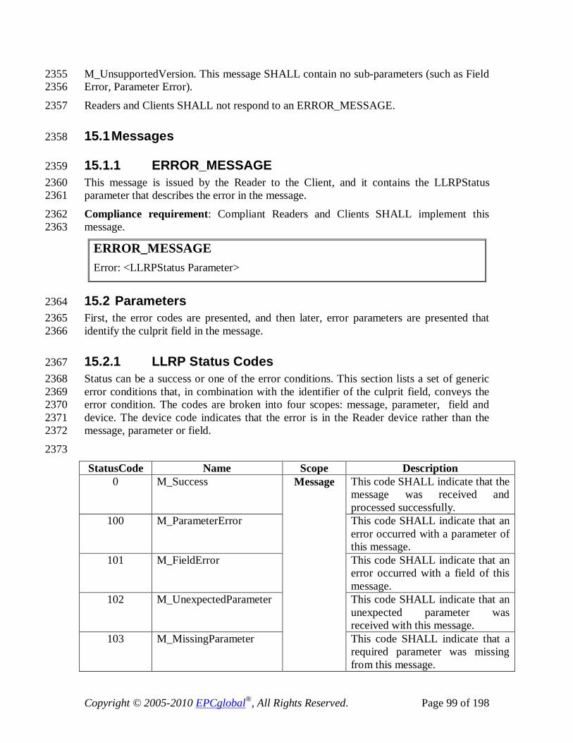
Copyright © 2005-2010 EPCglobal®, All Rights Reserved. Page 99 of 198
M_UnsupportedVersion. This message SHALL contain no sub-parameters (such as Field 2355 Error, Parameter Error). 2356
Readers and Clients SHALL not respond to an ERROR_MESSAGE. 2357
15.1 Messages 2358
15.1.1 ERROR_MESSAGE 2359 This message is issued by the Reader to the Client, and it contains the LLRPStatus 2360 parameter that describes the error in the message. 2361
Compliance requirement: Compliant Readers and Clients SHALL implement this 2362 message. 2363
ERROR_MESSAGE Error: <LLRPStatus Parameter>
15.2 Parameters 2364 First, the error codes are presented, and then later, error parameters are presented that 2365 identify the culprit field in the message. 2366
15.2.1 LLRP Status Codes 2367 Status can be a success or one of the error conditions. This section lists a set of generic 2368 error conditions that, in combination with the identifier of the culprit field, conveys the 2369 error condition. The codes are broken into four scopes: message, parameter, field and 2370 device. The device code indicates that the error is in the Reader device rather than the 2371 message, parameter or field. 2372
2373
StatusCode Name Scope Description 0 M_Success Message This code SHALL indicate that the
message was received and processed successfully.
100 M_ParameterError This code SHALL indicate that an error occurred with a parameter of this message.
101 M_FieldError This code SHALL indicate that an error occurred with a field of this message.
102 M_UnexpectedParameter This code SHALL indicate that an unexpected parameter was received with this message.
103 M_MissingParameter This code SHALL indicate that a required parameter was missing from this message.

Copyright © 2005-2010 EPCglobal®, All Rights Reserved. Page 100 of 198
104 M_DuplicateParameter This code SHALL indicate that a parameter, for which there must only be one instance at the Reader, was seen more than once in this message.
105 M_OverflowParameter This code SHALL indicate that the maximum number of instances of the parameter has been exceeded at the Reader.
106 M_OverflowField This code SHALL indicate that the maximum number of instances of the field has been exceeded at the Reader.
107 M_UnknownParameter This code SHALL indicate that an unknown parameter was received in the message.
108 M_UnknownField This code SHALL indicate that the field is unknown or not found at the Reader.
109 M_UnsupportedMessage This code SHALL indicate that an unsupported message type was received.
110 M_UnsupportedVersion This code SHALL indicate that the LLRP version in the received message is not supported by the Reader.
111 M_UnsupportedParameter This code MAY indicate that the Parameter in the received message is not supported by the Reader.
112 M_UnexpectedMessage This code SHALL indicate that the message received was unexpected by the Reader.
200 P_ParameterError Parameter This code SHALL indicate that an error occurred with a parameter of this parameter.
201 P_FieldError This code SHALL indicate that an error occurred with a field of this parameter.
202 P_UnexpectedParameter This code SHALL indicate that an unexpected parameter was received with this message.
203 P_MissingParameter This code SHALL indicate that a required parameter was missing from this parameter.
204 P_DuplicateParameter This code SHALL indicate that a parameter, for which there must

Copyright © 2005-2010 EPCglobal®, All Rights Reserved. Page 101 of 198
only be one instance, was seen more than once in this parameter.
205 P_OverflowParameter This code SHALL indicate that the maximum number of instances of the parameter has been exceeded at the Reader.
206 P_OverflowField This code SHALL indicate that the maximum number of instances of the field has been exceeded at the Reader.
207 P_UnknownParameter This code SHALL indicate that an unknown parameter was received with this message.
208 P_UnknownField This code SHALL indicate that the field is unknown or not found at the Reader.
209 P_UnsupportedParameter This code SHALL indicate that an unsupported parameter was received.
300 A_Invalid Field This code SHALL indicate that the field value was considered invalid for a non specific reason. An example is a message with invalid SpecID for a ROSpec or AccessSpec.
301 A_OutOfRange This code SHALL indicate that the field value did not fall within an acceptable range.
401 R_DeviceError Reader This code MAY indicate that there is a problem on the Reader rather than with a message, parameter, or field.
15.2.2 LLRPStatus Parameter 2374 Compliance requirement: Compliant Readers and Clients SHALL implement this 2375 parameter. 2376
LLRPStatus Parameter StatusCode: Integer.
Possible Values: See the error code table (section 15.2.1) for possible values within the Message, Parameter or Field scope. FieldError: <FieldError Parameter> [Optional]
ParameterError: <ParameterError Parameter> [Optional]

Copyright © 2005-2010 EPCglobal®, All Rights Reserved. Page 102 of 198
ErrorDescription: UTF-8 String
15.2.2.1 FieldError Parameter 2377 Compliance requirement: Compliant Readers and Clients SHALL implement this 2378 parameter. 2379
FieldError Parameter FieldNum: Integer. Field number for which the error applies. The fields are numbered after the order in which they appear in the parameter or message body.
Possible Values: 0-65535
ErrorCode: Integer. Possible Values:
See the error code table (section 15.2.1) for possible values within the Argument scope.
15.2.2.2 ParameterError Parameter 2380 Compliance requirement: Compliant Readers and Clients SHALL implement this 2381 parameter. 2382
ParameterError Parameter ParameterType: Integer. The parameter type that caused this error. Possible Values:
0 - 1023 ErrorCode: Integer.
Possible Values: See the error code table (section 15.2.1) for possible values within the Parameter scope. FieldError: <FieldError Parameter> [Optional]
ParameterError: <ParameterError Parameter> [Optional] 2383
16 Air Protocol Specific Parameters 2384 For each air protocol supported by LLRP, the following subsection, 16.1, provides a table 2385 cross-referencing LLRP parameters and their corresponding air protocol specific 2386 parameters. All LLRP air protocol specific parameters are specified in the next 2387 subsection, 16.2. 2388

Copyright © 2005-2010 EPCglobal®, All Rights Reserved. Page 103 of 198
16.1 LLRP Air Protocol Cross-Reference Tables 2389 Within this section there is a separate subsection for each air protocol specified by LLRP. 2390 Each air protocol subsection includes a table cross-referencing LLRP parameters and 2391 their corresponding air protocol specific parameters. 2392 Support for a new air protocol can be added to LLRP by adding new subsections to this 2393 section e.g., 15.1.2 and 15.1.3. 2394
16.1.1 Class-1 Generation-2 (C1G2) Air Protocol 2395 The Class-1 Generation-2 (C1G2) Air Protocol is specified by the EPCglobal Class-1 2396 Generation-2 UHF RFID Protocol v1.1.0 specification. 2397
The following table cross-references LLRP parameters to C1G2 air protocol specific 2398 parameters. 2399
LLRP Parameter (Section #) C1G2 Parameter (Section #)
AirProtocolLLRPCapabilities (10.2.3) C1G2LLRPCapabilities (16.2.1.1.1)
UHF_RFModeTable (10.2.4.1) UHFC1G2RFModeTable (16.2.1.1.2)
AirProtocolInventoryCommandSettings (13.2.6) C1G2InventoryCommand (16.2.1.2.1)
TagSpec (12.2.1.2) C1G2TagSpec (16.2.1.3.1)
OpSpec (12.2.1.2) C1G2OpSpec (16.2.1.3.2)
AirProtocolOpSpecList (12.2.2) C1G2OpSpec (16.2.1.3.2)
AirProtocolSpecificEPCMemorySelector (14.2.1.1) C1G2EPCMemorySelector (16.2.1.5.1)
AirProtocolTagData (14.2.3) C1G2PC, C1G2XPCW1, C1G2XPCW2 and C1G2CRC (16.2.1.5.2, 16.2.1.5.3, 16.2.1.5.4, 16.2.1.5.3)
AirProtocolSingulationDetails (14.2.6.9) C1G2SingulationDetails (16.2.1.5.6)
Op Spec Results (14.2.3) C1G2OpSpecResult (16.2.1.5.7)
16.2 LLRP Air Protocol Specific Parameters 2400 Within this section there is a separate subsection for each air protocol specified by LLRP. 2401 Each air protocol subsection includes a definition for each air protocol specific 2402 parameter. Section 16.1 above cross-references LLRP parameters to the air protocol 2403 specific parameters specified in this section. 2404

Copyright © 2005-2010 EPCglobal®, All Rights Reserved. Page 104 of 198
Support for a new air protocol can be added to LLRP by adding new subsections to this 2405 section e.g., 15.2.2 and 15.2.3. 2406
16.2.1 Class-1 Generation-2 (C1G2) Air Protocol 2407 The Class-1 Generation-2 (C1G2) Air Protocol is specified by EPCglobal Class-1 2408 Generation-2 UHF RFID Protocol v1.1.0 specification. 2409
The following subsections specify LLRP air protocol specific parameters. These 2410 subsections are partitioned to correlate with major sections of the LLRP specification: 2411
- Reader Device Capabilities 2412 - Inventory Operation 2413
- Access Operation 2414 - Reader Device Configuration 2415
- Reports 2416
16.2.1.1 Reader Device Capabilities 2417 This section of air protocol specific parameters corresponds to LLRP parameters 2418 specified in section 9. 2419
16.2.1.1.1 C1G2LLRPCapabilities Parameter 2420 Compliance requirement: Compliant Readers and Clients SHALL implement this 2421 parameter. Readers MAY support BlockErase, and MAY support BlockWrite. Readers 2422 SHALL support at least one select filter per query. 2423
C1G2LLRPCapabilities Parameter CanSupportBlockErase: Boolean
CanSupportBlockWrite: Boolean CanSupportBlockPermalock: Boolean
CanSupportTagRecommissioning: Boolean CanSupportUMIMethod2: Boolean
CanSupportXPC: Boolean MaxNumSelectFiltersPerQuery: Unsigned Short Integer. If set to zero, it indicates there is no maximum limit.
16.2.1.1.2 UHFC1G2RFModeTable Parameter 2424 This parameter carries the set of C1G2 RF modes that the Reader is capable of operating. 2425
Compliance requirement: Compliant Readers and Clients SHALL implement this 2426 parameter. 2427

Copyright © 2005-2010 EPCglobal®, All Rights Reserved. Page 105 of 198
UHFC1G2RFModeTable Parameter UHFC1G2RFModeSet: List of <UHFC1G2RFModeTableEntry Parameter>
16.2.1.1.2.1 UHFC1G2RFModeTableEntry Parameter 2428 This parameter carries the information for each UHFC1G2 RF mode. A mode that has 2429 been tested for conformance by the EPCGlobal Hardware Action Group’s Testing and 2430 Conformance (HAG T&C) group, is indicated using a conformance flag. 2431 Compliance requirement: Compliant Readers and Clients SHALL implement this 2432 parameter. 2433
UHFC1G2RFModeTableEntry Parameter Mode identifier: Unsigned Integer. This is a Reader defined identifier that the client may use to set the Gen2 operating parameters.
DR Value: Integer. Divide ratio. Possible Values: Value DR ----- -- 0 8 1 64/3 BDR Value: Integer. Backscatter data rate in bps.
Possible Values: 40000 – 640000 bps
M value: Integer. Modulation. Possible Values: Value M ------ --- 0 FM0 1 2 2 4 3 8 Forward link modulation: Integer
Possible Values: Value Modulation ------ ------------ 0 PR-ASK 1 SSB-ASK 2 DSB-ASK PIE Value: Integer. One thousand times the ratio of data-0 symbol length and data-1 symbol length in pulse-interval encoding. The C1G2 spec specifies a ratio range of 1.5 – 2.0. (see section 6.3.1.2.4 in [C1G2]).
Possible Values: 1500-2000

Copyright © 2005-2010 EPCglobal®, All Rights Reserved. Page 106 of 198
MinTariValue: Integer. Minimum Tari time in nanoseconds (see section 6.3.1.2.4 in [C1G2]) Possible Values:
6250-25000 MaxTariValue: Integer. Maximum Tari time in nanoseconds. (see section 6.3.1.2.4 in [C1G2]). Possible Values:
6250-25000 StepTariValue: Integer. Tari Step size in nanoseconds.(see section 6.3.1.2.4 in [C1G2])
Possible Values: 0 – 18750 nsec
Spectral Mask Indicator: Integer. Spectral mask characteristics of the mode. The Reader SHALL advertise this value if and only if the spectral mask value is valid for all the Tari steps in the range. Possible Values: Value Modulation ------ ------------ 0 Unknown 1 SI – Meets [C1G2] Single-Interrogator Mode Mask 2 MI – Meets [C1G2] Multi-Interrogator Mode Mask 3 DI - Meets [C1G2] Dense-Interrogator Mode Mask EPC HAG T&C Conformance: Boolean. This flag indicates if the Reader vendor has received the certification for the parameter sets specified in this mode. The Reader SHALL set this flag to true only if the Reader vendor has received EPCGlobal conformance for this mode as specified in EPCGlobal Testing and Conformance.
16.2.1.2 Inventory Operation 2434 This section of air protocol specific parameters corresponds to LLRP parameters 2435 specified in section 13.2.6. 2436
16.2.1.2.1 C1G2InventoryCommand Parameter 2437 This parameter defines the C1G2 inventory-specific settings to be used during a 2438 particular C1G2 inventory operation. This comprises of C1G2Filter Parameter, C1G2RF 2439 Parameter and C1G2Singulation Parameter. It is not necessary that the Filter, RF Control 2440 and Singulation Control Parameters be specified in each and every inventory command. 2441 They are optional parameters. If not specified, the default values in the Reader are used 2442 during the inventory operation. If multiple C1G2Filter parameters are encapsulated by the 2443 Client in the C1G2InventoryCommand parameter, the ordering of the filter parameters 2444 determine the order of C1G2 air-protocol commands (e.g., Select command) generated by 2445 the Reader. C1G2Filter parameters included in the C1G2InventoryCommand parameter 2446
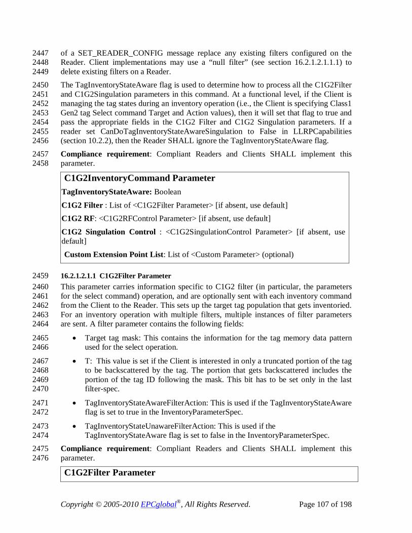
Copyright © 2005-2010 EPCglobal®, All Rights Reserved. Page 107 of 198
of a SET_READER_CONFIG message replace any existing filters configured on the 2447 Reader. Client implementations may use a “null filter” (see section 16.2.1.2.1.1.1) to 2448 delete existing filters on a Reader. 2449 The TagInventoryStateAware flag is used to determine how to process all the C1G2Filter 2450 and C1G2Singulation parameters in this command. At a functional level, if the Client is 2451 managing the tag states during an inventory operation (i.e., the Client is specifying Class1 2452 Gen2 tag Select command Target and Action values), then it will set that flag to true and 2453 pass the appropriate fields in the C1G2 Filter and C1G2 Singulation parameters. If a 2454 reader set CanDoTagInventoryStateAwareSingulation to False in LLRPCapabilities 2455 (section 10.2.2), then the Reader SHALL ignore the TagInventoryStateAware flag. 2456
Compliance requirement: Compliant Readers and Clients SHALL implement this 2457 parameter. 2458
C1G2InventoryCommand Parameter TagInventoryStateAware: Boolean
C1G2 Filter : List of <C1G2Filter Parameter> [if absent, use default] C1G2 RF: <C1G2RFControl Parameter> [if absent, use default]
C1G2 Singulation Control : <C1G2SingulationControl Parameter> [if absent, use default]
Custom Extension Point List: List of <Custom Parameter> (optional)
16.2.1.2.1.1 C1G2Filter Parameter 2459 This parameter carries information specific to C1G2 filter (in particular, the parameters 2460 for the select command) operation, and are optionally sent with each inventory command 2461 from the Client to the Reader. This sets up the target tag population that gets inventoried. 2462 For an inventory operation with multiple filters, multiple instances of filter parameters 2463 are sent. A filter parameter contains the following fields: 2464
• Target tag mask: This contains the information for the tag memory data pattern 2465 used for the select operation. 2466
• T: This value is set if the Client is interested in only a truncated portion of the tag 2467 to be backscattered by the tag. The portion that gets backscattered includes the 2468 portion of the tag ID following the mask. This bit has to be set only in the last 2469 filter-spec. 2470
• TagInventoryStateAwareFilterAction: This is used if the TagInventoryStateAware 2471 flag is set to true in the InventoryParameterSpec. 2472
• TagInventoryStateUnawareFilterAction: This is used if the 2473 TagInventoryStateAware flag is set to false in the InventoryParameterSpec. 2474
Compliance requirement: Compliant Readers and Clients SHALL implement this 2475 parameter. 2476
C1G2Filter Parameter

Copyright © 2005-2010 EPCglobal®, All Rights Reserved. Page 108 of 198
Target Tag Mask: <C1G2TagInventoryMask Parameter>
T: Integer Possible Values: Value Truncate action ----- --------------- 0 Unspecified: The Reader decides what truncate action to take. 1 Do not truncate 2 Truncate TagInventoryStateAwareAction: C1G2TagInventoryStateAwareFilterAction Parameter (optional)
TagInventoryStateUnawareAction: C1G2TagInventoryStateUnawareFilterAction Parameter (optional)
16.2.1.2.1.1.1 C1G2TagInventoryMask Parameter 2477 Compliance requirement: Compliant Readers and Clients SHALL implement this 2478 parameter. 2479
C1G2TagInventoryMask Parameter MB: Integer. C1G2 Tag memory bank.
Possible Values: 1-3. The mask used for the C1G2 select command applies only to EPC, TID or User memory, and not to Reserved memory (MB 0). Pointer: Unsigned Short Integer. The first (msb) bit location of the specified memory bank against which to compare the TagMask. TagMask: Bit array. The pattern against which to compare. If this array is empty (0 length), the tag mask is considered a “null filter” and will match all tags.
16.2.1.2.1.1.2 C1G2TagInventoryStateAwareFilterAction Parameter 2480 This parameter is used by the Client to manage the tag states during an inventory 2481 operation. In order to use this parameter during inventory, the TagInventoryStateAware 2482 flag is set to true in the InventoryParameterSpec. This parameter contains: 2483
• Target: This value indicates which flag in the tag to modify – whether the SL flag 2484 or its inventoried flag for a particular session. 2485
• Action describes the action for matching and non-matching tags. The actions are 2486 specific about the tag-inventory states - e.g., do nothing, assert or deassert SL, 2487 assign inventoried S0/S1/S2/S3 to A or B. 2488
Compliance requirement: Compliant Readers and Clients MAY implement this 2489 parameter. Readers that do not support tag inventory state aware singulation SHALL set 2490 CanDoTagInventoryStateAwareSingulation to false in LLRPCapabilities. 2491

Copyright © 2005-2010 EPCglobal®, All Rights Reserved. Page 109 of 198
C1G2TagInventoryStateAwareFilterAction Parameter Target: Integer
Possible Values: Value Definition ----- ----------
0 SL 1 Inventoried state for session S0 2 Inventoried state for session S1 3 Inventoried state for session S2 4 Inventoried state for session S3
Action : Integer Possible Values: Value Definition ----- ----------
0 Matching tags: assert SL or inventoried state A. Non-matching tags: deassert SL or inventoried state B. 1 Matching tags: assert SL or inventoried state A. Non-matching tags: do nothing 2 Matching tags: do nothing Non-matching tags: deassert SL or inventoried state B 3 Matching tags: negate SL or (AB, BA) Non-matching tags: do nothing 4 Matching tags: deassert SL or inventoried state B Non-matching tags: assert SL or inventoried state A 5 Matching tags: deassert SL or inventoried state B Non-matching tags: do nothing 6 Matching tags: do nothing Non-matching tags: assert SL or inventoried state A 7 Matching tags: do nothing Non-matching tags: negate SL or (AB, BA)
16.2.1.2.1.1.3 C1G2TagInventoryStateUnawareFilterAction Parameter 2492 This parameter is used by the Client if it does not want to manage the inventoried state of 2493 tags. Using this parameter, the Client instructs the Reader about the tags that should and 2494 should not participate in the inventory action. In order to use this parameter during 2495 inventory, the TagInventoryStateAware flag is set to false in the 2496 InventoryParameterSpec. This parameter contains: 2497
• Action describes the action for matching and non-matching tags. However, the 2498 action is simply specifying whether matching or non-matching tags partake in this 2499 inventory. The Reader is expected to handle the tag inventory states to facilitate 2500 this. 2501
In this parameter, Action=Select means include the corresponding tags in the Inventory, 2502 and Action=Unselect means exclude the corresponding tags in the Inventory. 2503

Copyright © 2005-2010 EPCglobal®, All Rights Reserved. Page 110 of 198
Compliance requirement: Compliant Readers and Clients SHALL implement this 2504 parameter. 2505
C1G2TagInventoryStateUnawareFilterAction Parameter Action : Integer
Possible Values: Value Matching Tags Non-matching Tags ----- ------------- ----------------- 0 Select Unselect 1 Select Do nothing 2 Do nothing Unselect 3 Unselect Do nothing 4 Unselect Select 5 Do nothing Select
16.2.1.2.1.2 C1G2RF Control Parameter 2506 This Parameter carries the settings relevant to RF forward and reverse link control in the 2507 C1G2 air protocol. This is basically the C1G2 RF Mode and the Tari value to use for the 2508 inventory operation. 2509
Compliance requirement: Compliant Readers and Clients SHALL implement this 2510 parameter. 2511
C1G2RFControl Parameter ModeIndex: Unsigned Integer. This is an index into the UHFC1G2RFModeTable. Tari: Integer. Value of Tari to use for this mode specified in nsec. This is specified if the mode selected has a Tari range. If the selected mode has a range, and the Tari is set to zero, the Reader implementation picks up any Tari value within the range. If the selected mode has a range, and the specified Tari is out of that range and is not set to zero, an error message is generated.
Possible Values: 0 or 6250-25000 nsec
16.2.1.2.1.3 C1G2SingulationControl Parameter 2512 This C1G2SingulationControl Parameter provides controls particular to the singulation 2513 process in the C1G2 air protocol. The singulation process is started using a Query 2514 command in the C1G2 protocol. The Query command describes the session number, tag 2515 state, the start Q value to use, and the RF link parameters. The RF link parameters are 2516 specified using the C1G2RFControl Parameter (see section 16.2.1.2.1.2). This 2517 Singulation Parameter specifies the session, tag state and description of the target 2518 singulation environment. The following attributes are specified to provide guidance to the 2519 Reader for the singulation algorithm: 2520
• Tag transit time: This is the measure of expected tag mobility in the field of view 2521 of the antenna where this inventory operation is getting executed. 2522

Copyright © 2005-2010 EPCglobal®, All Rights Reserved. Page 111 of 198
• Tag population: This is the expected tag population in the field of view of the 2523 antenna. 2524
In addition, the Singulation Parameter allows setting of the following: 2525
• Session ID: This is the C1G2 session number that the tags use to update the 2526 inventory state upon successful singulation. 2527
• TagInventoryStateAwareSingulationAction: This is used if the 2528 TagInventoryStateAware flag is set to true in the InventoryParameterSpec. 2529
o I: This is the inventoried state of the target tag population in the selected 2530 session and it corresponds to the Target field of the Class1 Gen2 Query 2531 command. Only tags that match the session state participate in the 2532 inventory round. If the TagInventoryStateAware flag is false, then the 2533 Reader ignores this field, and its up to the Reader implementation to 2534 determine the value of I used in the inventory round. 2535
o S: This is the state of the SL flag in the tag and it corresponds to the Sel 2536 field of the Class1 Gen2 Query command. Only tags that match that tag 2537 state participate in the inventory round. If the TagInventoryStateAware 2538 flag is false, then the Reader ignores this field, and its up to the Reader 2539 implementation to determine the value of S used in the inventory round. 2540
If a reader sets CanDoTagInventoryStateAwareSingulation to False in LLRPCapabilities 2541 (section 10.2.2), it SHALL ignore the TagInventoryStateAwareSingulationAction field. 2542
Compliance requirement: Compliant Readers and Clients SHALL implement this 2543 parameter. 2544
C1G2SingulationControl Parameter Session: Integer. Session number to use for the inventory operation. Possible Values:
0-3 Tag population: Unsigned Short Integer. An estimate of the tag population in view of the RF field of the antenna. Tag transit time: Unsigned Integer. An estimate of the time a tag will typically remain in the RF field of the antenna specified in milliseconds.
TagInventoryStateAwareSingulationAction: <C1G2TagInventoryStateAwareSingulationAction Parameter> (optional)
16.2.1.2.1.3.1 C1G2TagInventoryStateAwareSingulationAction Parameter 2545 See C1G2SingulationControl above for a description of this parameter. 2546
Compliance requirement: Compliant Readers and Clients MAY implement this 2547 parameter. Readers that do not support tag inventory state aware singulation SHALL set 2548 CanDoTagInventoryStateAwareSingulation to false in LLRPCapabilities. 2549

Copyright © 2005-2010 EPCglobal®, All Rights Reserved. Page 112 of 198
C1G2TagInventoryStateAwareSingulationAction Parameter I : Integer
Possible Values: Value Definition ----- ---------- 0 State A 1 State B S : Integer
Possible Values: Value Definition ----- ---------- 0 SL 1 ~SL S_All : Integer
If set to zero, reference the S field. If set to one, the S field is ignored. Possible Values: Value Definition ----- ---------- 0 No 1 All
16.2.1.3 Access Operation 2550 This section of air protocol specific parameters corresponds to LLRP parameters 2551 specified in section 11.2.4. 2552
16.2.1.3.1 C1G2TagSpec Parameter 2553 This parameter describes the target tag population on which certain operations have to be 2554 performed. This Parameter is similar to the selection C1G2Filter Parameter described 2555 earlier. However, because these tags are stored in the Reader's memory and ternary 2556 comparisons are to be allowed for, each bit i in the target tag is represented using 2 bits - 2557 bit i in mask, and bit i in tag pattern. If bit i in the mask is zero, then bit i of the target tag 2558 is a don’t care (X); if bit i in the mask is one, then bit i of the target tag is bit i of the tag 2559 pattern. For example, “all tags” is specified using a mask length of zero. 2560
This parameter can carry up to two tag patterns. If more than one pattern is present, a 2561 Boolean AND is implied. Each tag pattern has a match or a non-match flag, allowing (A 2562 and B,!A and B, !A and !B, A and !B), where A and B are the tag patterns. 2563 The tagSpec contains: 2564
• TagPattern1 2565
• TagPattern2 2566

Copyright © 2005-2010 EPCglobal®, All Rights Reserved. Page 113 of 198
Compliance requirement: Compliant Readers and Clients SHALL implement this 2567 parameter. 2568
C1G2TagSpec Parameter TagPattern1: <C1G2TargetTag Parameter>
TagPattern2: <C1G2TargetTag Parameter> [optional]
16.2.1.3.1.1 C1G2TargetTag Parameter 2569 If Length is zero, this pattern will match all tags regardless of MB, pointer, mask and 2570 data. 2571 Compliance requirement: Compliant Readers and Clients SHALL implement this 2572 parameter. 2573
C1G2TargetTag Parameter MB: Integer. Memory bank. Possible Values: 0-3.
Pointer: Unsigned Short Integer. The address of the first (msb) bit against which to apply the Tag Mask and compare with the value.
TagMask : Bit array TagData: Bit array
Match: Boolean
16.2.1.3.2 C1G2 OpSpec Parameters 2574 This section describes the C1G2 specific OpSpec parameters that are sent as part of the 2575 AccessSpec. Each OpSpec parameter has an OpSpecID that is used when reporting 2576 results of the operation. 2577
16.2.1.3.2.1 C1G2Read Parameter 2578 MB is the memory bank to use. WordPtr is the starting word address. WordCount is the 2579 number of 16-bit words to be read. Following is text reproduced from the C1G2 2580 specification regarding WordCount=0. [If WordCount = 0, the tag backscatters the 2581 contents of the chosen memory bank starting at WordPtr and ending at the end of the 2582 bank, unless MB = 1, in which case the Tag shall backscatter the EPC memory contents 2583 starting at WordPtr and ending at the length of the EPC specified by the first 5 bits of the 2584 PC if WordPtr lies within the EPC, and shall backscatter the EPC memory contents 2585 starting at WordPtr and ending at the end of EPC memory if WordPtr lies outside the 2586 EPC.] 2587 Access Password is the password used by the Reader to transition the tag to the secure 2588 state so that it can read protected tag memory regions. For example, the Tag’s Reserved 2589 memory is locked but not permalocked, meaning that the Reader must issue the access 2590 password and transition the Tag to the secured state before performing the read operation. 2591
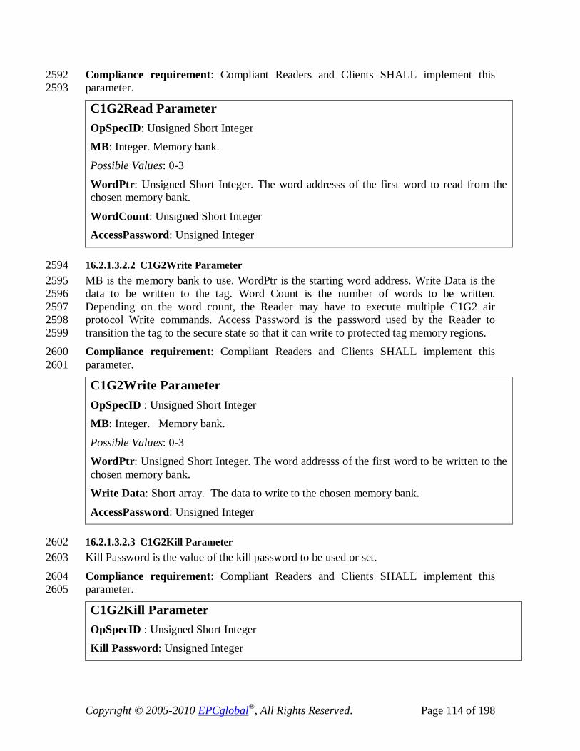
Copyright © 2005-2010 EPCglobal®, All Rights Reserved. Page 114 of 198
Compliance requirement: Compliant Readers and Clients SHALL implement this 2592 parameter. 2593
C1G2Read Parameter OpSpecID: Unsigned Short Integer
MB: Integer. Memory bank. Possible Values: 0-3
WordPtr: Unsigned Short Integer. The word addresss of the first word to read from the chosen memory bank.
WordCount: Unsigned Short Integer AccessPassword: Unsigned Integer
16.2.1.3.2.2 C1G2Write Parameter 2594 MB is the memory bank to use. WordPtr is the starting word address. Write Data is the 2595 data to be written to the tag. Word Count is the number of words to be written. 2596 Depending on the word count, the Reader may have to execute multiple C1G2 air 2597 protocol Write commands. Access Password is the password used by the Reader to 2598 transition the tag to the secure state so that it can write to protected tag memory regions. 2599 Compliance requirement: Compliant Readers and Clients SHALL implement this 2600 parameter. 2601
C1G2Write Parameter OpSpecID : Unsigned Short Integer MB: Integer. Memory bank.
Possible Values: 0-3 WordPtr: Unsigned Short Integer. The word addresss of the first word to be written to the chosen memory bank. Write Data: Short array. The data to write to the chosen memory bank.
AccessPassword: Unsigned Integer
16.2.1.3.2.3 C1G2Kill Parameter 2602 Kill Password is the value of the kill password to be used or set. 2603
Compliance requirement: Compliant Readers and Clients SHALL implement this 2604 parameter. 2605
C1G2Kill Parameter OpSpecID : Unsigned Short Integer Kill Password: Unsigned Integer

Copyright © 2005-2010 EPCglobal®, All Rights Reserved. Page 115 of 198
16.2.1.3.2.4 C1G2Recommission Parameter 2606 This parameter allows a tag to be recommissioned instead of killed. See the Class1 Gen2 2607 V1.2.0 specification for a definition of each of the recommission bits. 2608 Compliance requirement: Compliant Readers and Clients MAY implement this 2609 parameter. Readers that do not support C1G2 Recommissioning SHALL set 2610 CanSupportTagRecommissioning to false in C1G2LLRPCapabilities. If such a Reader 2611 receives an ADD_ACCESSSPEC with an AccessSpec that contained this OpSpec 2612 parameter, the Reader SHALL return an error for that message and not add the 2613 AccessSpec. 2614
C1G2Recommission Parameter OpSpecID: Unsigned Short Integer
Kill Password: Unsigned Integer
LSB: Boolean (see section 6.3.2.10 of the C1G2 V1.2.0 specification) 2SB: Boolean (see section 6.3.2.10 of the C1G2 V1.2.0 specification)
3SB: Boolean (see section 6.3.2.10 of the C1G2 V1.2.0 specification)
16.2.1.3.2.5 C1G2Lock Parameter 2615 This parameter contains the definition of the access privilege updates 2616 (read/write/permalock) to be performed in various locations of the memory. The five data 2617 fields for which we can define access control using the lock command are: Kill Password, 2618 Access Password, EPC memory, TID memory and User memory. The access privilege 2619 updates are expressed as a list of C1G2LockPayload Parameters, one for each memory 2620 location. 2621
The Access Password provides the password to enter the secured state. A Reader can 2622 perform a lock operation on a tag only if the tag is in the secured state. The tag enters the 2623 secured state only using the Access Password (if a non-zero value). 2624 Compliance requirement: Compliant Readers and Clients SHALL implement this 2625 parameter. 2626
C1G2Lock Parameter OpSpecID : Unsigned Short Integer
LockCommandPayloadList: List of <C1G2LockPayload Parameter> Access Password: Unsigned Integer
16.2.1.3.2.5.1 C1G2LockPayload Parameter 2627 This parameter contains the definition of the access privilege updates 2628 (read/write/permalock) to be performed for a single location of the tag memory. The five 2629 data fields for which we can define access control using the lock command are: Kill 2630 Password, Access Password, EPC memory, TID memory and User memory. 2631
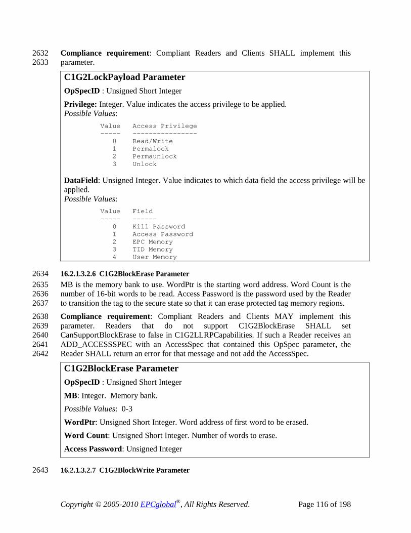
Copyright © 2005-2010 EPCglobal®, All Rights Reserved. Page 116 of 198
Compliance requirement: Compliant Readers and Clients SHALL implement this 2632 parameter. 2633
C1G2LockPayload Parameter OpSpecID : Unsigned Short Integer
Privilege: Integer. Value indicates the access privilege to be applied. Possible Values: Value Access Privilege ----- ---------------- 0 Read/Write 1 Permalock 2 Permaunlock 3 Unlock DataField: Unsigned Integer. Value indicates to which data field the access privilege will be applied. Possible Values: Value Field ----- ------ 0 Kill Password 1 Access Password 2 EPC Memory 3 TID Memory 4 User Memory
16.2.1.3.2.6 C1G2BlockErase Parameter 2634 MB is the memory bank to use. WordPtr is the starting word address. Word Count is the 2635 number of 16-bit words to be read. Access Password is the password used by the Reader 2636 to transition the tag to the secure state so that it can erase protected tag memory regions. 2637 Compliance requirement: Compliant Readers and Clients MAY implement this 2638 parameter. Readers that do not support C1G2BlockErase SHALL set 2639 CanSupportBlockErase to false in C1G2LLRPCapabilities. If such a Reader receives an 2640 ADD_ACCESSSPEC with an AccessSpec that contained this OpSpec parameter, the 2641 Reader SHALL return an error for that message and not add the AccessSpec. 2642
C1G2BlockErase Parameter OpSpecID : Unsigned Short Integer
MB: Integer. Memory bank. Possible Values: 0-3
WordPtr: Unsigned Short Integer. Word address of first word to be erased. Word Count: Unsigned Short Integer. Number of words to erase.
Access Password: Unsigned Integer
16.2.1.3.2.7 C1G2BlockWrite Parameter 2643

Copyright © 2005-2010 EPCglobal®, All Rights Reserved. Page 117 of 198
MB is the memory bank to use. WordPtr is the starting word address. Word Count is the 2644 number of 16-bit words to be written. Depending on the word count, the Reader may 2645 have to execute multiple C1G2 air protocol block write commands. Write Data is the data 2646 to be written to the tag. Access Password is the password used by the Reader to transition 2647 the tag to the secure state so that it can write to protected tag memory regions. 2648 Compliance requirement: Compliant Readers and Clients MAY implement this 2649 parameter. Readers that do not support C1G2BlockWrite SHALL set 2650 CanSupportBlockWrite to false in C1G2LLRPCapabilities. If such a Reader receives an 2651 ADD_ACCESSSPEC with an AccessSpec that contained this OpSpec parameter, the 2652 Reader SHALL return an error for that message and not add the AccessSpec. 2653
C1G2BlockWrite Parameter OpSpecID : Unsigned Short Integer
MB: Integer. Memory bank. Possible Values: 0-3
WordPtr: Unsigned Short Integer. Word address of first word to be written. Write Data: Short array
Access Password: Unsigned Integer
16.2.1.3.2.8 C1G2BlockPermalock Parameter 2654 MB (MemBank), BlockPointer, and BlockMask fields are equivalent to the Class1 Gen2 2655 BlockPermalock fields. AccessPassword is the password required to put the tag into the 2656 secured state as required to execute the BlockPermalock command. 2657
Compliance requirement: Compliant Readers and Clients MAY implement this 2658 parameter. Readers that do not support C1G2BlockPermalock SHALL set 2659 CanSupportBlockPermalock to false in C1G2LLRPCapabilities. If such a Reader 2660 receives an ADD_ACCESSSPEC with an AccessSpec that contained this OpSpec 2661 parameter, the Reader SHALL return an error for that message and not add the 2662 AccessSpec. 2663
C1G2BlockPermalock Parameter OpSpecID : Unsigned Short Integer MB: Integer. Memory bank.
Possible Values: 0-3 BlockPointer: Unsigned Short Integer. Specifies the starting address for BlockMask in units of 16 blocks. BlockMask: Unsigned Short Integer Array. The blocks to lock, starting at BlockPointer and ending ((16*(BlockMask array length)) – 1) blocks later. AccessPassword: Unsigned Integer

Copyright © 2005-2010 EPCglobal®, All Rights Reserved. Page 118 of 198
16.2.1.3.2.9 C1G2GetBlockPermalockStatus Parameter 2664 This parameter retrieves the BlockPermalock status from a tag. MB (MemBank), 2665 BlockPointer, and BlockRange fields are equivalent to the Class1 Gen2 BlockPermalock 2666 fields. AccessPassword is the password required to put the tag into the secured state as 2667 required to execute the BlockPermalock command. 2668 Compliance requirement: Compliant Readers and Clients MAY implement this 2669 parameter. Readers that do not support C1G2BlockPermalock SHALL set 2670 CanSupportBlockPermalock to false in C1G2LLRPCapabilities. If such a Reader 2671 receives an ADD_ACCESSSPEC with an AccessSpec that contained this OpSpec 2672 parameter, the Reader SHALL return an error for that message and not add the 2673 AccessSpec. 2674
C1G2GetBlockPermalockStatus Parameter OpSpecID : Unsigned Short Integer
MB: Integer. Memory bank. Possible Values: 0-3
BlockPointer: Unsigned Short Integer. Specifies the starting address to retrieve in units of 16 blocks.
BlockRange: Unsigned Short Integer. The range of blocks to retrieve, starting at BlockPointer and ending ((16*BlockRange) – 1) blocks later.
AccessPassword: Unsigned Integer
16.2.1.4 Reader Device Configuration 2675 This section of air protocol specific parameters corresponds to LLRP parameters 2676 specified in section 13. The only air protocol specific parameter is 2677 AirProtocolInventoryCommandSettings parameter in the AntennaConfiguration (section 2678 13.2.6). The C1G2 specific InventoryCommand is already defined in section 16.2.1.2.1. 2679
16.2.1.5 Reports 2680 This section of air protocol specific parameters corresponds to LLRP parameters 2681 specified in section 14.2.1.1. 2682
16.2.1.5.1 C1G2EPCMemorySelector Parameter 2683 This parameter is used to determine what contents are of interest in the C1G2EPC 2684 memory bank for reporting. If enableCRC, enablePC, and enableXPC are set to false, 2685 then only the EPC is returned in the RO Report. If enablePC is set to true, then the PC 2686 bits are returned with the EPC in the RO Report. If enableCRC is set to true, then the 2687 CRC bits are returned with the EPC in the RO Report. If enableXPC is set to true, then 2688 the XPC bits are returned with the EPC in the RO Report in the C1G2XPCW1 and 2689 C1G2XPCW2 parameters, depending on what was backscattered by the tag. If 2690 enableXPC is set to true, Client implementations SHALL accept C1G2XPCW1 and 2691 C1G2XPCW2 in the RO Report.. 2692

Copyright © 2005-2010 EPCglobal®, All Rights Reserved. Page 119 of 198
Compliance requirement: Compliant Readers and Clients SHALL implement this 2693 parameter. 2694
C1G2EPCMemorySelector enablePC: Boolean
enableCRC: Boolean enableXPC: Boolean
16.2.1.5.2 C1G2PC Parameter 2695 Compliance requirement: Compliant Readers and Clients SHALL implement this 2696 parameter. 2697
C1G2PC Parameter PC bits: Unsigned Short Integer
16.2.1.5.3 C1G2XPCW1 Parameter 2698 This parameter is included within a TagReportData parameter if enableXPC is set to true 2699 and the tag backscattered XPC_W1. 2700 Compliance requirement: Compliant Readers and Clients MAY implement this 2701 parameter. Readers that do not support C1G2XPC SHALL set CanSupportXPC to false 2702 in C1G2LLRPCapabilities. 2703
C1G2XPCW1 Parameter XPC_W1: Unsigned Short Integer
16.2.1.5.4 C1G2XPCW2 Parameter 2704 This parameter is included within a TagReportData parameter if enableXPC is set to true 2705 and the tag backscattered XPC_W2. 2706 Compliance requirement: Compliant Readers and Clients MAY implement this 2707 parameter. Readers that do not support C1G2XPC SHALL set CanSupportXPC to false 2708 in C1G2LLRPCapabilities. 2709
C1G2XPCW2 Parameter XPC_W2: Unsigned Short Integer
16.2.1.5.5 C1G2CRC Parameter 2710 Compliance requirement: Compliant Readers and Clients SHALL implement this 2711 parameter. 2712
C1G2CRC Parameter CRC: Unsigned Short Integer

Copyright © 2005-2010 EPCglobal®, All Rights Reserved. Page 120 of 198
16.2.1.5.6 C1G2SingulationDetails Parameter 2713 Compliance requirement: Compliant Readers and Clients MAY implement this 2714 parameter. 2715
C1G2SingulationDetails Parameter NumCollisionSlots: Unsigned Short Integer. The number of slots detected as collided over the duration of this report.
NumEmptySlots: Unsigned Short Integer. The number of slots detected as empty over the duration of this report.
16.2.1.5.7 C1G2 OpSpec Results 2716
16.2.1.5.7.1 C1G2ReadOpSpecResult Parameter 2717 Compliance requirement: Compliant Readers and Clients SHALL implement this 2718 parameter. 2719
C1G2ReadOpSpecResult Parameter OpSpecID: Unsigned Short Integer
ReadData: Short Array. The data read from the RFID tag. Result: Integer
Possible Values: Value Definition ----- ---------- 0 Success 1 Non-specific tag error 2 No response from tag 3 Non-specific reader error 4 Memory overrun error 5 Memory locked error 6 Incorrect password error
16.2.1.5.7.2 C1G2WriteOpSpecResult Parameter 2720 Compliance requirement: Compliant Readers and Clients SHALL implement this 2721 parameter. 2722
C1G2WriteOpSpecResult Parameter OpSpecID: Unsigned Short Integer
NumWordsWritten: Unsigned Short Integer. The number of words written as a result of this OpSpec. If the number of words written is not equal to the length of the data pattern to write, the Result below SHALL be non-zero. Result: Integer
Possible Values: Value Definition

Copyright © 2005-2010 EPCglobal®, All Rights Reserved. Page 121 of 198
----- ---------- 0 Success 1 Tag memory overrun error 2 Tag memory locked error 3 Insufficient power to perform memory-write operation
4 Non-specific tag error 5 No response from tag 6 Non-specific reader error 7 Incorrect password error
16.2.1.5.7.3 C1G2KillOpSpecResult Parameter 2723 Compliance requirement: Compliant Readers and Clients SHALL implement this 2724 parameter. 2725
C1G2KillOpSpecResult Parameter OpSpecID: Unsigned Short Integer Result: Integer
Possible Values: Value Definition ----- ---------- 0 Success 1 Zero kill password error 2 Insufficient power to perform kill operation
3 Non-specific tag error 4 No response from tag 5 Non-specific reader error 6 Incorrect password error
16.2.1.5.7.4 C1G2RecommissionOpSpecResult Parameter 2726 Compliance requirement: Compliant Readers and Clients MAY implement this 2727 parameter. Readers that do not support C1G2 Recommissioning SHALL set 2728 CanSupportTagRecommissioning to false in C1G2LLRPCapabilities. 2729
C1G2RecommissionOpSpecResult Parameter OpSpecID: Unsigned Short Integer Result: Integer
Possible Values: Value Definition ----- ---------- 0 Success 1 Zero kill password error 2 Insufficient power to perform recommission operation
3 Non-specific tag error 4 No response from tag 5 Non-specific reader error 6 Incorrect password error

Copyright © 2005-2010 EPCglobal®, All Rights Reserved. Page 122 of 198
16.2.1.5.7.5 C1G2LockOpSpecResult Parameter 2730 Compliance requirement: Compliant Readers and Clients SHALL implement this 2731 parameter. 2732
C1G2LockOpSpecResult Parameter OpSpecID: Unsigned Short Integer
Result: Integer Possible Values: Value Definition ----- ---------- 0 Success 1 Insufficient power to perform lock operation 2 Non-specific tag error 3 No response from tag 4 Non-specific reader error 5 Incorrect password error 6 Tag memory overrun error 7 Tag memory locked error
16.2.1.5.7.6 C1G2BlockEraseOpSpecResult Parameter 2733 Compliance requirement: Compliant Readers and Clients MAY implement this 2734 parameter. Readers that do not support C1G2 Block Erase SHALL set 2735 CanSupportBlockErase to false in C1G2LLRPCapabilities. 2736
C1G2BlockEraseOpSpecResult Parameter OpSpecID: Unsigned Short Integer Result: Integer
Possible Values: Value Definition ----- ---------- 0 Success 1 Tag memory overrun error 2 Tag memory locked error 3 Insufficient power to perform block erase operation
4 Non-specific tag error 5 No response from tag 6 Non-specific reader error 7 Incorrect password error
16.2.1.5.7.7 C1G2BlockWriteOpSpecResult Parameter 2737 Compliance requirement: Compliant Readers and Clients MAY implement this 2738 parameter. Readers that do not support C1G2 Block Write SHALL set 2739 CanSupportBlockWrite to false in C1G2LLRPCapabilities. 2740
C1G2BlockWriteOpSpecResult Parameter

Copyright © 2005-2010 EPCglobal®, All Rights Reserved. Page 123 of 198
OpSpecID: Unsigned Short Integer
NumWordsWritten: Unsigned Short Integer Result: Integer
Possible Values: Value Definition ----- ---------- 0 Success 1 Tag memory overrun error 2 Tag memory locked error 3 Insufficient power to perform memory-write operation
4 Non-specific tag error 5 No response from tag 6 Non-specific reader error 7 Incorrect password error
16.2.1.5.7.8 C1G2BlockPermalockOpSpecResult Parameter 2741 Compliance requirement: Compliant Readers and Clients MAY implement this 2742 parameter. Readers that do not support C1G2 Block Permalock SHALL set 2743 CanSupportBlockPermalock to false in C1G2LLRPCapabilities. 2744
C1G2BlockPermalockOpSpecResult Parameter OpSpecID: Unsigned Short Integer
Result: Integer Possible Values: Value Definition ----- ---------- 0 Success 1 Insufficient power to perform block permalock operation
2 Non-specific tag error 3 No response from tag 4 Non-specific reader error 5 Incorrect password error 6 Tag memory overrun error
16.2.1.5.7.9 C1G2GetBlockPermalockStatusOpSpecResult Parameter 2745 Compliance requirement: Compliant Readers and Clients MAY implement this 2746 parameter. Readers that do not support C1G2 Block Permalock SHALL set 2747 CanSupportBlockPermalock to false in C1G2LLRPCapabilities. 2748
C1G2GetBlockPermalockStatusOpSpecResult Parameter OpSpecID: Unsigned Short Integer PermalockStatus: Unsigned Short Integer Array. Specifies the Permalock status of each block requested. Result: Integer

Copyright © 2005-2010 EPCglobal®, All Rights Reserved. Page 124 of 198
Possible Values: Value Definition ----- ---------- 0 Success
1 Non-specific tag error 2 No response from tag 3 Non-specific reader error 4 Incorrect password error 5 Tag memory overrun error

Copyright © 2005-2010 EPCglobal®, All Rights Reserved. Page 125 of 198
17 Binary Encoding for LLRP 2749 This section contains the specific formats and operations for the binary encoding of the 2750 Low Level Reader Protocol. All fields and parameters must be encoded in the order 2751 shown in the diagrams in this section. This section does not contain information that has 2752 been generalized in the main body of the document. Refer to sections 8-16 for the 2753 description of the messages and the parameters and fields in the messages. 2754
The binary encoding is based on a stream of octets. Each octet represents 8 bits of 2755 information. Octets within the data stream are serialized according to the particular 2756 transport mechanism over which this binding is carried. Octet numbering shown in this 2757 section is in network order. For example, in Figure 14, the first octet that a LLRP 2758 endpoint receives contains Rsvd, Ver and 2 bits of Message type. 2759 2760
0 1 2 3 0 1 2 3 4 5 6 7 8 9 0 1 2 3 4 5 6 7 8 9 0 1 2 3 4 5 6 7 8 9 0 1
Rsvd Ver Message Type Message Length [31:16] Message Length [15:0] Message ID[31:16]
Message ID[15:0] Message Value
Figure 14: Network Order 2761 Figure 15 illustrates the bit order inside the fields. 2762 2763
2 1 0 2 1 0 9 8 7 6 5 4 3 2 1 0 31 30 29 28 27 26 25 24 23 22 21 20 19 18 17 16 Rsvd Ver Message Type Message Length [31:16]
Figure 15: Bit Order in Fields 2764 Integer numbers SHALL be encoded in network byte order with the most significant byte 2765 of the integer being sent first (big-Endian). Bit arrays are aligned to the most significant 2766 bit. Bit arrays are padded to an octet boundary. Pad bits SHALL be ignored by the 2767 Reader and Client. 2768
The length of all messages within the binary encoding SHALL be multiples of octets. 2769 This means all parameters within the binary encoding SHALL be multiples of octets. 2770 This includes any custom or vendor specific parameter. All the messages and parameters 2771 in this section have been padded with zero to ensure that the length is a multiple of octets. 2772
Reserved Bits 2773
Reserved bits are added to fields where necessary to preserve octet-alignment of the 2774 binary LLRP stream. Future versions of LLRP may use reserved bits to extend certain 2775 types of fields (like Boolean, assuming the reserved bits are towards the MSb of the 2776 field), or to add new fields. Reserved bits are subject to the following rules: 2777
• Clients SHALL ignore reserved bits. 2778
• Readers SHALL error on non-zero reserved bits. 2779

Copyright © 2005-2010 EPCglobal®, All Rights Reserved. Page 126 of 198
• Both Clients and Readers SHALL set reserved bits to zero. 2780
Notations 2781
Inside a message or a parameter, 2782
• If a parameter X is denoted simply as X, it means that X is mandatory and appears 2783 once in the message. 2784
• If a parameter X is denoted as X (0-n), it means that X is optional in the message, 2785 and it can appear multiple times in the message. 2786
• If a parameter X is denoted as X (0-1), it means that X is optional in the message 2787 and that it can appear at most once in the message. 2788
• If a parameter X is denoted as X (1-n), it means that X is mandatory and can 2789 appear multiple times in the message. 2790
Negative Numbers 2791
Negative numbers are represented using twos complement notation. 2792
17.1 Messages 2793 2794
0 1 2 3 0 1 2 3 4 5 6 7 8 9 0 1 2 3 4 5 6 7 8 9 0 1 2 3 4 5 6 7 8 9 0 1
Rsvd Ver Message Type Message Length [31:16] Message Length [15:0] Message ID[31:16]
Message ID[15:0] Message Value
2795 Reserved bits: 3 bits 2796
The reserved bits are reserved for future extensions. All reserved bits in messages SHALL be set to 0. 2797 2798
Ver: 3 bits 2799 The version of LLRP. Implementations of LLRP based on this specification are using the value 0x2 2800 except where explicitly noted otherwise (see Table 3 for the mapping between the values for this field 2801 and the protocol versions). Other values are reserved for future use. 2802 2803
Message Type: 10 bits 2804 The type of LLRP message being carried in the message. 2805 2806
Message Length: 32 bits 2807 This value represents the size of the entire message in octets starting from bit offset 0 of the first word. 2808 Therefore, if the Message Value field is zero-length, the Length field will be set to 10. 2809 2810
Message ID: 32 bits 2811 As stated earlier, the communications between the Client and the Reader are primarily of a request-2812 response type - requests/commands from the Client to the Reader, and responses from the Reader to the 2813 Client. In order to facilitate multiple outstanding commands/requests from the Client, LLRP uses a 2814

Copyright © 2005-2010 EPCglobal®, All Rights Reserved. Page 127 of 198
Message sequence number in each message. The Message sequence number is used to correlate a 2815 response with the original request. This sequence number is local to the LLRP channel. 2816
2817 Message Value: variable length 2818
Dependent on the Message Type. 2819 2820

Copyright © 2005-2010 EPCglobal®, All Rights Reserved. Page 128 of 198
17.1.1 GET_SUPPORTED_VERSION 2821 0 1 2 3 0 1 2 3 4 5 6 7 8 9 0 1 2 3 4 5 6 7 8 9 0 1 2 3 4 5 6 7 8 9 0 1
Rsvd Ver Message Type =46 Message Length [31:16] Message Length [15:0] Message ID[31:16]
Message ID[15:0]
2822 See Section 9.1.1. 2823 2824
17.1.2 GET_SUPPORTED_VERSION_RESPONSE 2825 0 1 2 3 0 1 2 3 4 5 6 7 8 9 0 1 2 3 4 5 6 7 8 9 0 1 2 3 4 5 6 7 8 9 0 1
Rsvd Ver Message Type =56 Message Length [31:16] Message Length [15:0] Message ID[31:16]
Message ID[15:0] CurrentVersion SupportedVersion LLRPStatus Parameter
2826 See Section 9.1.2. 2827 2828
17.1.3 SET_PROTOCOL_VERSION 2829 0 1 2 3 0 1 2 3 4 5 6 7 8 9 0 1 2 3 4 5 6 7 8 9 0 1 2 3 4 5 6 7 8 9 0 1
Rsvd Ver Message Type =47 Message Length [31:16] Message Length [15:0] Message ID[31:16]
Message ID[15:0] ProtocolVersion
2830 See Section 9.1.3. 2831 2832
17.1.4 SET_PROTOCOL_VERSION_RESPONSE 2833 0 1 2 3 0 1 2 3 4 5 6 7 8 9 0 1 2 3 4 5 6 7 8 9 0 1 2 3 4 5 6 7 8 9 0 1
Rsvd Ver Message Type =57 Message Length [31:16] Message Length [15:0] Message ID[31:16]
Message ID[15:0] LLRPStatus Parameter
2834 See Section 9.1.4. 2835 2836
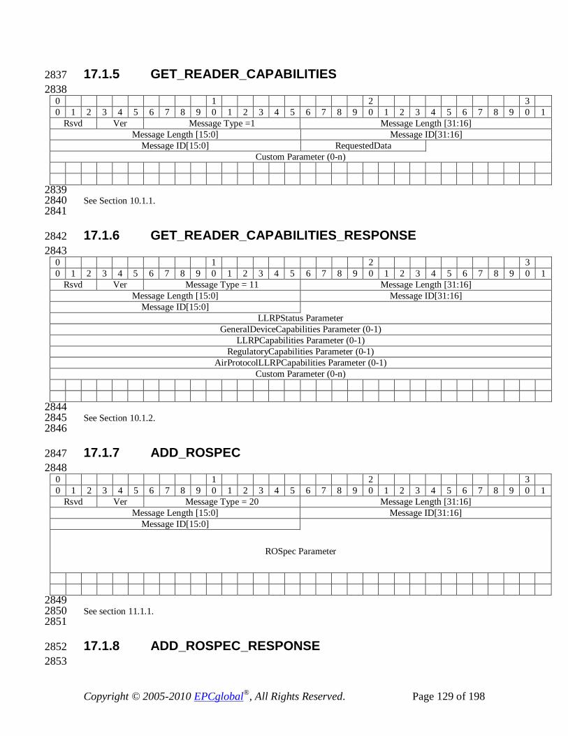
Copyright © 2005-2010 EPCglobal®, All Rights Reserved. Page 129 of 198
17.1.5 GET_READER_CAPABILITIES 2837 2838
0 1 2 3 0 1 2 3 4 5 6 7 8 9 0 1 2 3 4 5 6 7 8 9 0 1 2 3 4 5 6 7 8 9 0 1
Rsvd Ver Message Type =1 Message Length [31:16] Message Length [15:0] Message ID[31:16]
Message ID[15:0] RequestedData Custom Parameter (0-n)
2839 See Section 10.1.1. 2840 2841
17.1.6 GET_READER_CAPABILITIES_RESPONSE 2842 2843
0 1 2 3 0 1 2 3 4 5 6 7 8 9 0 1 2 3 4 5 6 7 8 9 0 1 2 3 4 5 6 7 8 9 0 1
Rsvd Ver Message Type = 11 Message Length [31:16] Message Length [15:0] Message ID[31:16]
Message ID[15:0] LLRPStatus Parameter
GeneralDeviceCapabilities Parameter (0-1) LLRPCapabilities Parameter (0-1)
RegulatoryCapabilities Parameter (0-1) AirProtocolLLRPCapabilities Parameter (0-1)
Custom Parameter (0-n)
2844 See Section 10.1.2. 2845 2846
17.1.7 ADD_ROSPEC 2847 2848
0 1 2 3 0 1 2 3 4 5 6 7 8 9 0 1 2 3 4 5 6 7 8 9 0 1 2 3 4 5 6 7 8 9 0 1
Rsvd Ver Message Type = 20 Message Length [31:16] Message Length [15:0] Message ID[31:16]
Message ID[15:0]
ROSpec Parameter
2849 See section 11.1.1. 2850 2851
17.1.8 ADD_ROSPEC_RESPONSE 2852 2853

Copyright © 2005-2010 EPCglobal®, All Rights Reserved. Page 130 of 198
0 1 2 3 0 1 2 3 4 5 6 7 8 9 0 1 2 3 4 5 6 7 8 9 0 1 2 3 4 5 6 7 8 9 0 1
Rsvd Ver Message Type = 30 Message Length [31:16] Message Length [15:0] Message ID[31:16]
Message ID[15:0] LLRPStatus Parameter
2854 See section 11.1.2. 2855 2856
17.1.9 DELETE_ROSPEC 2857 2858
0 1 2 3 0 1 2 3 4 5 6 7 8 9 0 1 2 3 4 5 6 7 8 9 0 1 2 3 4 5 6 7 8 9 0 1
Rsvd Ver Message Type = 21 Message Length [31:16] Message Length [15:0] Message ID[31:16]
Message ID[15:0] ROSpecID[31:16] ROSpecID[15:0]
2859 See section 11.1.3. 2860 2861
17.1.10 DELETE_ROSPEC_RESPONSE 2862 2863
0 1 2 3 0 1 2 3 4 5 6 7 8 9 0 1 2 3 4 5 6 7 8 9 0 1 2 3 4 5 6 7 8 9 0 1
Rsvd Ver Message Type =31 Message Length [31:16] Message Length [15:0] Message ID[31:16]
Message ID[15:0] LLRPStatus Parameter
2864 See section 11.1.4. 2865 2866
17.1.11 START_ROSPEC 2867 2868
0 1 2 3 0 1 2 3 4 5 6 7 8 9 0 1 2 3 4 5 6 7 8 9 0 1 2 3 4 5 6 7 8 9 0 1
Rsvd Ver Message Type = 22 Message Length [31:16] Message Length [15:0] Message ID[31:16]
Message ID[15:0] ROSpecID[31:16] ROSpecID[15:0]
2869 See section 11.1.5. 2870

Copyright © 2005-2010 EPCglobal®, All Rights Reserved. Page 131 of 198
2871
17.1.12 START_ROSPEC_RESPONSE 2872 2873
0 1 2 3 0 1 2 3 4 5 6 7 8 9 0 1 2 3 4 5 6 7 8 9 0 1 2 3 4 5 6 7 8 9 0 1
Rsvd Ver Message Type = 32 Message Length [31:16] Message Length [15:0] Message ID[31:16]
Message ID[15:0] LLRPStatus Parameter
2874 See section 11.1.6. 2875 2876
17.1.13 STOP_ROSPEC 2877 0 1 2 3 0 1 2 3 4 5 6 7 8 9 0 1 2 3 4 5 6 7 8 9 0 1 2 3 4 5 6 7 8 9 0 1
Rsvd Ver Message Type = 23 Message Length [31:16] Message Length [15:0] Message ID[31:16]
Message ID[15:0] ROSpecID[31:16] ROSpecID[15:0]
2878 See section 11.1.7. 2879 2880
17.1.14 STOP_ROSPEC_RESPONSE 2881 0 1 2 3 0 1 2 3 4 5 6 7 8 9 0 1 2 3 4 5 6 7 8 9 0 1 2 3 4 5 6 7 8 9 0 1
Rsvd Ver Message Type = 33 Message Length [31:16] Message Length [15:0] Message ID[31:16]
Message ID[15:0] LLRPStatus Parameter
2882 See section 11.1.8. 2883 2884
17.1.15 ENABLE_ROSPEC 2885 0 1 2 3 0 1 2 3 4 5 6 7 8 9 0 1 2 3 4 5 6 7 8 9 0 1 2 3 4 5 6 7 8 9 0 1
Rsvd Ver Message Type = 24 Message Length [31:16] Message Length [15:0] Message ID[31:16]
Message ID[15:0] ROSpecID[31:16] ROSpecID[15:0]

Copyright © 2005-2010 EPCglobal®, All Rights Reserved. Page 132 of 198
2886 See section 11.1.9. 2887 2888
17.1.16 ENABLE_ROSPEC_RESPONSE 2889 0 1 2 3 0 1 2 3 4 5 6 7 8 9 0 1 2 3 4 5 6 7 8 9 0 1 2 3 4 5 6 7 8 9 0 1
Rsvd Ver Message Type = 34 Message Length [31:16] Message Length [15:0] Message ID[31:16]
Message ID[15:0] LLRPStatus Parameter
2890 See section 11.1.10. 2891 2892
17.1.17 DISABLE_ROSPEC 2893 0 1 2 3 0 1 2 3 4 5 6 7 8 9 0 1 2 3 4 5 6 7 8 9 0 1 2 3 4 5 6 7 8 9 0 1
Rsvd Ver Message Type = 25 Message Length [31:16] Message Length [15:0] Message ID[31:16]
Message ID[15:0] ROSpecID[31:16] ROSpecID[15:0]
2894 See section 11.1.11. 2895 2896
17.1.18 DISABLE_ROSPEC_RESPONSE 2897 0 1 2 3 0 1 2 3 4 5 6 7 8 9 0 1 2 3 4 5 6 7 8 9 0 1 2 3 4 5 6 7 8 9 0 1
Rsvd Ver Message Type = 35 Message Length [31:16] Message Length [15:0] Message ID[31:16]
Message ID[15:0] LLRPStatus Parameter
2898 See section 11.1.12. 2899 2900
17.1.19 GET_ROSPECS 2901 2902
0 1 2 3 0 1 2 3 4 5 6 7 8 9 0 1 2 3 4 5 6 7 8 9 0 1 2 3 4 5 6 7 8 9 0 1
Rsvd Ver Message Type = 26 Message Length [31:16] Message Length [15:0] Message ID[31:16]
Message ID[15:0]
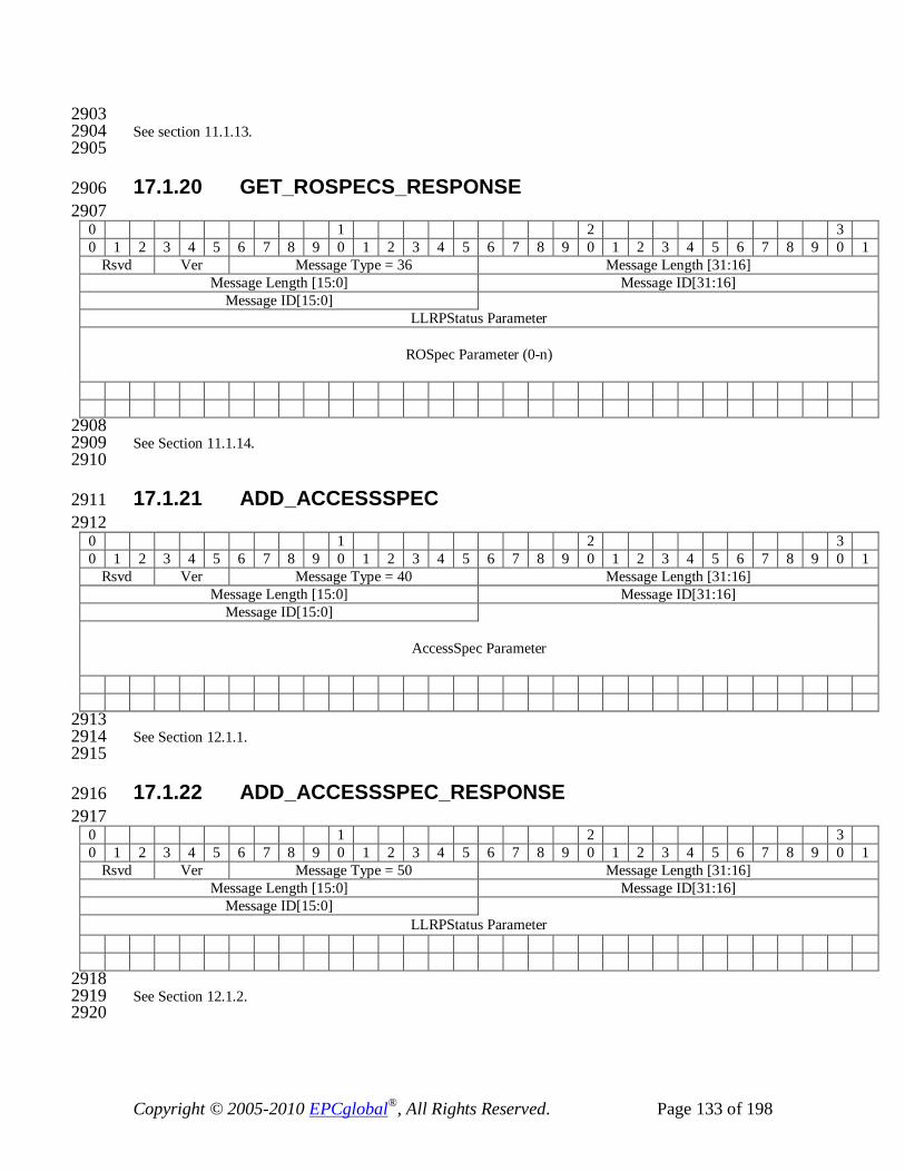
Copyright © 2005-2010 EPCglobal®, All Rights Reserved. Page 133 of 198
2903 See section 11.1.13. 2904 2905
17.1.20 GET_ROSPECS_RESPONSE 2906 2907
0 1 2 3 0 1 2 3 4 5 6 7 8 9 0 1 2 3 4 5 6 7 8 9 0 1 2 3 4 5 6 7 8 9 0 1
Rsvd Ver Message Type = 36 Message Length [31:16] Message Length [15:0] Message ID[31:16]
Message ID[15:0] LLRPStatus Parameter
ROSpec Parameter (0-n)
2908 See Section 11.1.14. 2909 2910
17.1.21 ADD_ACCESSSPEC 2911 2912
0 1 2 3 0 1 2 3 4 5 6 7 8 9 0 1 2 3 4 5 6 7 8 9 0 1 2 3 4 5 6 7 8 9 0 1
Rsvd Ver Message Type = 40 Message Length [31:16] Message Length [15:0] Message ID[31:16]
Message ID[15:0]
AccessSpec Parameter
2913 See Section 12.1.1. 2914 2915
17.1.22 ADD_ACCESSSPEC_RESPONSE 2916 2917
0 1 2 3 0 1 2 3 4 5 6 7 8 9 0 1 2 3 4 5 6 7 8 9 0 1 2 3 4 5 6 7 8 9 0 1
Rsvd Ver Message Type = 50 Message Length [31:16] Message Length [15:0] Message ID[31:16]
Message ID[15:0] LLRPStatus Parameter
2918 See Section 12.1.2. 2919 2920
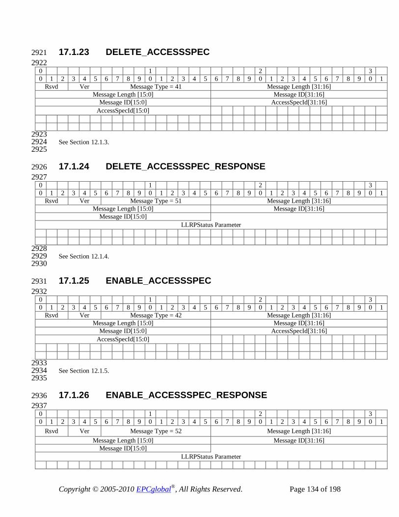
Copyright © 2005-2010 EPCglobal®, All Rights Reserved. Page 134 of 198
17.1.23 DELETE_ACCESSSPEC 2921 2922
0 1 2 3 0 1 2 3 4 5 6 7 8 9 0 1 2 3 4 5 6 7 8 9 0 1 2 3 4 5 6 7 8 9 0 1
Rsvd Ver Message Type = 41 Message Length [31:16] Message Length [15:0] Message ID[31:16]
Message ID[15:0] AccessSpecId[31:16] AccessSpecId[15:0]
2923 See Section 12.1.3. 2924 2925
17.1.24 DELETE_ACCESSSPEC_RESPONSE 2926 2927
0 1 2 3 0 1 2 3 4 5 6 7 8 9 0 1 2 3 4 5 6 7 8 9 0 1 2 3 4 5 6 7 8 9 0 1
Rsvd Ver Message Type = 51 Message Length [31:16] Message Length [15:0] Message ID[31:16]
Message ID[15:0] LLRPStatus Parameter
2928 See Section 12.1.4. 2929 2930
17.1.25 ENABLE_ACCESSSPEC 2931 2932
0 1 2 3 0 1 2 3 4 5 6 7 8 9 0 1 2 3 4 5 6 7 8 9 0 1 2 3 4 5 6 7 8 9 0 1
Rsvd Ver Message Type = 42 Message Length [31:16] Message Length [15:0] Message ID[31:16]
Message ID[15:0] AccessSpecId[31:16] AccessSpecId[15:0]
2933 See Section 12.1.5. 2934 2935
17.1.26 ENABLE_ACCESSSPEC_RESPONSE 2936 2937
0 1 2 3 0 1 2 3 4 5 6 7 8 9 0 1 2 3 4 5 6 7 8 9 0 1 2 3 4 5 6 7 8 9 0 1
Rsvd Ver Message Type = 52 Message Length [31:16] Message Length [15:0] Message ID[31:16]
Message ID[15:0] LLRPStatus Parameter
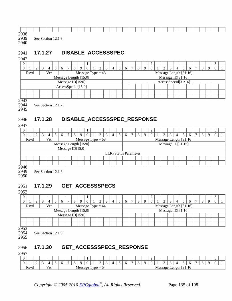
Copyright © 2005-2010 EPCglobal®, All Rights Reserved. Page 135 of 198
2938 See Section 12.1.6. 2939 2940
17.1.27 DISABLE_ACCESSSPEC 2941 2942
0 1 2 3 0 1 2 3 4 5 6 7 8 9 0 1 2 3 4 5 6 7 8 9 0 1 2 3 4 5 6 7 8 9 0 1
Rsvd Ver Message Type = 43 Message Length [31:16] Message Length [15:0] Message ID[31:16]
Message ID[15:0] AccessSpecId[31:16] AccessSpecId[15:0]
2943 See Section 12.1.7. 2944 2945
17.1.28 DISABLE_ACCESSSPEC_RESPONSE 2946 2947
0 1 2 3 0 1 2 3 4 5 6 7 8 9 0 1 2 3 4 5 6 7 8 9 0 1 2 3 4 5 6 7 8 9 0 1
Rsvd Ver Message Type = 53 Message Length [31:16] Message Length [15:0] Message ID[31:16]
Message ID[15:0] LLRPStatus Parameter
2948 See Section 12.1.8. 2949 2950
17.1.29 GET_ACCESSSPECS 2951 2952
0 1 2 3 0 1 2 3 4 5 6 7 8 9 0 1 2 3 4 5 6 7 8 9 0 1 2 3 4 5 6 7 8 9 0 1
Rsvd Ver Message Type = 44 Message Length [31:16] Message Length [15:0] Message ID[31:16]
Message ID[15:0]
2953 See Section 12.1.9. 2954 2955
17.1.30 GET_ACCESSSPECS_RESPONSE 2956 2957
0 1 2 3 0 1 2 3 4 5 6 7 8 9 0 1 2 3 4 5 6 7 8 9 0 1 2 3 4 5 6 7 8 9 0 1
Rsvd Ver Message Type = 54 Message Length [31:16]
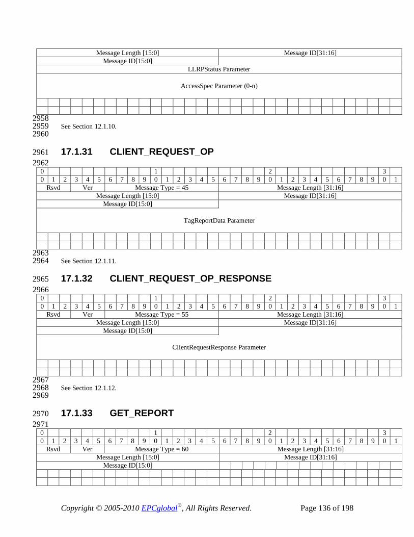
Copyright © 2005-2010 EPCglobal®, All Rights Reserved. Page 136 of 198
Message Length [15:0] Message ID[31:16] Message ID[15:0]
LLRPStatus Parameter
AccessSpec Parameter (0-n)
2958 See Section 12.1.10. 2959 2960
17.1.31 CLIENT_REQUEST_OP 2961 2962
0 1 2 3 0 1 2 3 4 5 6 7 8 9 0 1 2 3 4 5 6 7 8 9 0 1 2 3 4 5 6 7 8 9 0 1
Rsvd Ver Message Type = 45 Message Length [31:16] Message Length [15:0] Message ID[31:16]
Message ID[15:0]
TagReportData Parameter
2963 See Section 12.1.11. 2964
17.1.32 CLIENT_REQUEST_OP_RESPONSE 2965 2966
0 1 2 3 0 1 2 3 4 5 6 7 8 9 0 1 2 3 4 5 6 7 8 9 0 1 2 3 4 5 6 7 8 9 0 1
Rsvd Ver Message Type = 55 Message Length [31:16] Message Length [15:0] Message ID[31:16]
Message ID[15:0]
ClientRequestResponse Parameter
2967 See Section 12.1.12. 2968 2969
17.1.33 GET_REPORT 2970 2971
0 1 2 3 0 1 2 3 4 5 6 7 8 9 0 1 2 3 4 5 6 7 8 9 0 1 2 3 4 5 6 7 8 9 0 1
Rsvd Ver Message Type = 60 Message Length [31:16] Message Length [15:0] Message ID[31:16]
Message ID[15:0]
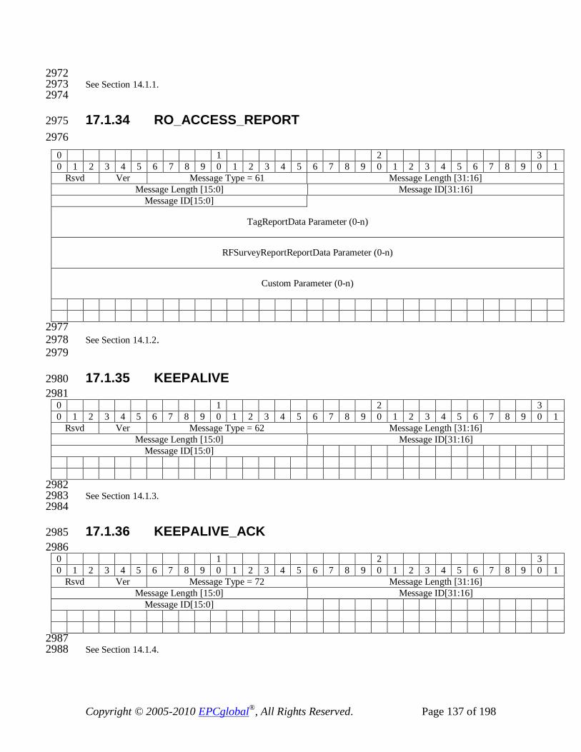
Copyright © 2005-2010 EPCglobal®, All Rights Reserved. Page 137 of 198
2972 See Section 14.1.1. 2973 2974
17.1.34 RO_ACCESS_REPORT 2975 2976
0 1 2 3 0 1 2 3 4 5 6 7 8 9 0 1 2 3 4 5 6 7 8 9 0 1 2 3 4 5 6 7 8 9 0 1
Rsvd Ver Message Type = 61 Message Length [31:16] Message Length [15:0] Message ID[31:16]
Message ID[15:0]
TagReportData Parameter (0-n)
RFSurveyReportReportData Parameter (0-n)
Custom Parameter (0-n)
2977 See Section 14.1.2. 2978 2979
17.1.35 KEEPALIVE 2980 2981
0 1 2 3 0 1 2 3 4 5 6 7 8 9 0 1 2 3 4 5 6 7 8 9 0 1 2 3 4 5 6 7 8 9 0 1
Rsvd Ver Message Type = 62 Message Length [31:16] Message Length [15:0] Message ID[31:16]
Message ID[15:0]
2982 See Section 14.1.3. 2983 2984
17.1.36 KEEPALIVE_ACK 2985 2986
0 1 2 3 0 1 2 3 4 5 6 7 8 9 0 1 2 3 4 5 6 7 8 9 0 1 2 3 4 5 6 7 8 9 0 1
Rsvd Ver Message Type = 72 Message Length [31:16] Message Length [15:0] Message ID[31:16]
Message ID[15:0]
2987 See Section 14.1.4. 2988

Copyright © 2005-2010 EPCglobal®, All Rights Reserved. Page 138 of 198
17.1.37 READER_EVENT_NOTIFICATION 2989 2990
0 1 2 3 0 1 2 3 4 5 6 7 8 9 0 1 2 3 4 5 6 7 8 9 0 1 2 3 4 5 6 7 8 9 0 1
Rsvd Ver Message Type = 63 Message Length [31:16] Message Length [15:0] Message ID[31:16]
Message ID[15:0]
ReaderEventNotificationData Parameter
2991 See Section 14.1.5. 2992 2993
17.1.38 ENABLE_EVENTS_AND_REPORTS 2994 2995
0 1 2 3 0 1 2 3 4 5 6 7 8 9 0 1 2 3 4 5 6 7 8 9 0 1 2 3 4 5 6 7 8 9 0 1
Rsvd Ver Message Type = 64 Message Length [31:16] Message Length [15:0] Message ID[31:16]
Message ID[15:0]
2996 See Section 14.1.6. 2997
17.1.39 ERROR_MESSAGE 2998 2999
0 1 2 3 0 1 2 3 4 5 6 7 8 9 0 1 2 3 4 5 6 7 8 9 0 1 2 3 4 5 6 7 8 9 0 1
Rsvd Ver Message Type = 100 Message Length [31:16] Message Length [15:0] Message ID[31:16]
Message ID[15:0]
LLRPStatus Parameter
3000 See Section 15.1.1. 3001 3002
17.1.40 GET_READER_CONFIG 3003 3004
0 1 2 3 0 1 2 3 4 5 6 7 8 9 0 1 2 3 4 5 6 7 8 9 0 1 2 3 4 5 6 7 8 9 0 1
Rsvd Ver Message Type = 2 Message Length [31:16] Message Length [15:0] Message ID[31:16]

Copyright © 2005-2010 EPCglobal®, All Rights Reserved. Page 139 of 198
Message ID[15:0] Antenna ID RequestedData GPIPortNum GPOPortNum[15:8]
GPOPortNum[7:0] Custom Parameter (0-n)
3005 See Section 13.1.1. 3006 3007
17.1.41 GET_READER_CONFIG_RESPONSE 3008 3009
0 1 2 3 0 1 2 3 4 5 6 7 8 9 0 1 2 3 4 5 6 7 8 9 0 1 2 3 4 5 6 7 8 9 0 1
Rsvd Ver Message Type = 12 Message Length [31:16] Message Length [15:0] Message ID[31:16]
Message ID[15:0] LLRPStatus Parameter
Identification Parameter (0-1) AntennaProperties Parameter (0-n)
AntennaConfiguration Parameter (0-n) ReaderEventNotificationSpec Parameter (0-1)
ROReportSpec Parameter (0-1) AccessReportSpec Parameter (0-1)
LLRPConfigurationStateValue Parameter (0-1) KeepaliveSpec Parameter (0-1)
GPIPortCurrentState Parameter (0-n) GPOWriteData Parameter (0-n)
EventsAndReports Parameter (0-1) Custom Parameter (0-n)
3010 See Section 13.1.2. 3011 3012
17.1.42 SET_READER_CONFIG 3013 3014
0 1 2 3 0 1 2 3 4 5 6 7 8 9 0 1 2 3 4 5 6 7 8 9 0 1 2 3 4 5 6 7 8 9 0 1
Rsvd Ver Message Type = 3 Message Length [31:16] Message Length [15:0] Message ID[31:16]
Message ID[15:0] R Reserved ReaderEventNotificationSpec Parameter (0-1)
AntennaProperties Parameter (0-n) AntennaConfiguration Parameter (0-n)
ROReportSpec Parameter (0-1) AccessReportSpec Parameter (0-1)
KeepaliveSpec Parameter (0-1) GPOWriteData Parameter (0-n)
GPIPortCurrentState Parameter (0-n) EventsAndReports Parameter (0-1)
Custom Parameter (0-n)

Copyright © 2005-2010 EPCglobal®, All Rights Reserved. Page 140 of 198
3015 Abbreviations 3016 R - ResetToFactoryDefaults 3017 3018 See section 13.1.3. 3019 3020
17.1.43 SET_READER_CONFIG_RESPONSE 3021 3022
0 1 2 3 0 1 2 3 4 5 6 7 8 9 0 1 2 3 4 5 6 7 8 9 0 1 2 3 4 5 6 7 8 9 0 1
Rsvd Ver Message Type = 13 Message Length [31:16] Message Length [15:0] Message ID[31:16]
Message ID[15:0] LLRPStatus Parameter
3023 See section 13.1.4. 3024 3025
17.1.44 CLOSE_CONNECTION 3026 3027
0 1 2 3 0 1 2 3 4 5 6 7 8 9 0 1 2 3 4 5 6 7 8 9 0 1 2 3 4 5 6 7 8 9 0 1
Rsvd Ver Message Type = 14 Message Length [31:16] Message Length [15:0] Message ID[31:16]
Message ID[15:0]
3028 See section 13.1.5. 3029 3030
17.1.45 CLOSE_CONNECTION_RESPONSE 3031 3032
0 1 2 3 0 1 2 3 4 5 6 7 8 9 0 1 2 3 4 5 6 7 8 9 0 1 2 3 4 5 6 7 8 9 0 1
Rsvd Ver Message Type = 4 Message Length [31:16] Message Length [15:0] Message ID[31:16]
Message ID[15:0] LLRPStatus Parameter
3033 See section 13.1.6. 3034 3035

Copyright © 2005-2010 EPCglobal®, All Rights Reserved. Page 141 of 198
17.1.46 CUSTOM_MESSAGE 3036 3037
0 1 2 3 0 1 2 3 4 5 6 7 8 9 0 1 2 3 4 5 6 7 8 9 0 1 2 3 4 5 6 7 8 9 0 1
Rsvd Ver Message Type = 1023 Message Length [31:16] Message Length [15:0] Message ID[31:16]
Message ID[15:0] Vendor Identifier [31:16] Vendor Identifier [15:0] Message Subtype
Vendor Specified Payload
3038 See Section 8.1. 3039 3040
17.2 LLRP Parameters 3041 LLRP parameters are defined in the following subsections with the exception that the air 3042 protocol specific LLRP parameters are defined in Section 17.3. The binary encoding of 3043 LLRP uses two different encodings of parameters: Type-length-value (TLV) encoded 3044 parameters, and Type-value (TV) encoded parameters. The TV encoding is only used for 3045 encoding parameters that are fixed-length, and are in Reports and Notifications from the 3046 Reader. The use of a compact encoding (i.e., TV) for the Reports and Notifications helps 3047 improve the network efficiency. 3048
17.2.1 TLV and TV Encoding of LLRP Parameter 3049 The type of encoding (TLV or TV) is determined based on the value of bit 0 in the 3050 parameter header. All TLV-encoded Parameters SHALL have a 0 in bit 0 of the header. 3051 All TV-encoded Parameters SHALL have a 1 in bit 0 of the header. 3052
17.2.1.1 TLV-Parameters 3053 LLRP TLV-Parameters have the following encoding structure. 3054
0 1 2 3 0 1 2 3 4 5 6 7 8 9 0 1 2 3 4 5 6 7 8 9 0 1 2 3 4 5 6 7 8 9 0 1
Reserved Parameter Type Parameter Length
Parameter Value
3055 3056 Reserved bits: 6 bits 3057
The reserved bits are reserved for future extensions. All reserved bits SHALL be set to 0. 3058 3059
Parameter Type: 10 bits 3060 This is the type of LLRP parameter being carried in the message. The parameter number space for the 3061

Copyright © 2005-2010 EPCglobal®, All Rights Reserved. Page 142 of 198
TLV-parameters is 128 – 2047. The number space 0-127 is reserved for TV-parameters. 3062 3063
Parameter Length: 16 bits 3064 This value represents the size of the entire parameter in bytes starting from bit offset 0 of the first word. 3065 Therefore, if the Parameter Value field is zero-length, the Parameter Length field will be set to 4. 3066 3067
Parameter Value: variable length 3068 Dependent on the Parameter Type. 3069
17.2.1.1.1 Encoding Guidelines for TLV-Parameters 3070 The following rules apply to TLV-Parameters: 3071
• Parameters may contain mandatory and optional fields. 3072
• Parameter fields may be passed by value or by sub-parameter. 3073
• Mandatory fields will always be present and optional fields may or may not be 3074 present. 3075
• Mandatory fields of fixed length will be passed by value only, using the order, 3076 size and alignment defined in this document. 3077
• A mandatory field of variable length must be passed by value if it is the only 3078 field, mandatory or optional, of variable length in that parameter. 3079
• A parameter with multiple mandatory or optional fields of variable length must 3080 pass them as sub-parameters. 3081
• A parameter containing a field of variable length being passed by value may not 3082 contain sub-parameters. 3083
• Optional fields will always be passed as sub-parameters. 3084 The following rules apply to sub-parameters: 3085
• Sub-parameters follow all parameter rules. 3086
• A sub-parameter is a parameter that is encompassed within the length of a 3087 preceeding parameter and adds to the dataset of the encapsulating parameter. 3088
ParameterA-length---------------------------+ 3089 Data | 3090 ParameterB-length---+ | 3091 Data <-+ | 3092 ParameterC-length---------------+ | 3093 Data | | 3094 ParameterD-length---+ | | 3095 Data <-+ <-+ <-+ 3096
3097 • Sub-parameters may be mandatory or optional. 3098
17.2.1.2 TV-Parameters 3099 LLRP TV-Parameters have the following encoding structure. 3100
0 1 2 3 0 1 2 3 4 5 6 7 8 9 0 1 2 3 4 5 6 7 8 9 0 1 2 3 4 5 6 7 8 9 0 1

Copyright © 2005-2010 EPCglobal®, All Rights Reserved. Page 143 of 198
1 Parameter Type Parameter Value
3101 Parameter Type: 8 bits 3102
This is the type of LLRP parameter being carried in the message. The parameter number space for the 3103 TV-parameters is 1 – 127. The number space 128-2047 is reserved for TLV-parameters. 3104 3105
Parameter Value: variable length 3106 Dependent on the Parameter Type. 3107 3108
17.2.1.2.1 Encoding Guidelines for TV-Parameters 3109 The following rule applies to TV-Parameters: 3110
• TV-Parameters cannot contain sub-parameters (TLV or TV-Parameters). 3111 3112
17.2.2 General Parameters 3113
17.2.2.1 UTCTimestamp Parameter 3114 0 1 2 3 0 1 2 3 4 5 6 7 8 9 0 1 2 3 4 5 6 7 8 9 0 1 2 3 4 5 6 7 8 9 0 1
Reserved Type = 128 Length Microseconds [63:32] Microseconds [31:0]
3115 See Section 7.1.3.1.1.1. 3116 3117
17.2.2.2 Uptime Parameter 3118 0 1 2 3 0 1 2 3 4 5 6 7 8 9 0 1 2 3 4 5 6 7 8 9 0 1 2 3 4 5 6 7 8 9 0 1
Reserved Type = 129 Length MicroSeconds [63:32] Microseconds [31:0]
3119 See section 7.1.3.1.1.2. 3120 3121 3122
17.2.3 Reader Device Capabilities Parameters 3123
17.2.3.1 GeneralDeviceCapabilities Parameter 3124 3125
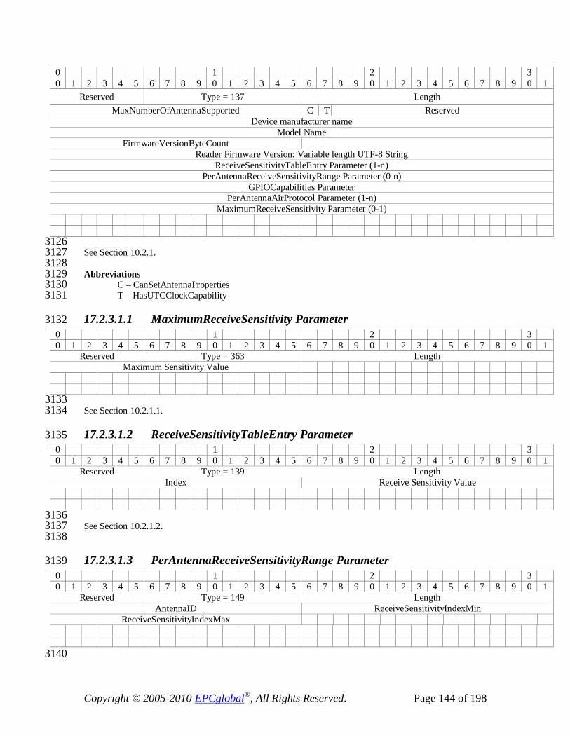
Copyright © 2005-2010 EPCglobal®, All Rights Reserved. Page 144 of 198
0 1 2 3 0 1 2 3 4 5 6 7 8 9 0 1 2 3 4 5 6 7 8 9 0 1 2 3 4 5 6 7 8 9 0 1
Reserved Type = 137 Length MaxNumberOfAntennaSupported C T Reserved
Device manufacturer name Model Name
FirmwareVersionByteCount Reader Firmware Version: Variable length UTF-8 String
ReceiveSensitivityTableEntry Parameter (1-n) PerAntennaReceiveSensitivityRange Parameter (0-n)
GPIOCapabilities Parameter PerAntennaAirProtocol Parameter (1-n)
MaximumReceiveSensitivity Parameter (0-1)
3126 See Section 10.2.1. 3127 3128 Abbreviations 3129
C – CanSetAntennaProperties 3130 T – HasUTCClockCapability 3131
17.2.3.1.1 MaximumReceiveSensitivity Parameter 3132 0 1 2 3 0 1 2 3 4 5 6 7 8 9 0 1 2 3 4 5 6 7 8 9 0 1 2 3 4 5 6 7 8 9 0 1
Reserved Type = 363 Length Maximum Sensitivity Value
3133 See Section 10.2.1.1. 3134
17.2.3.1.2 ReceiveSensitivityTableEntry Parameter 3135 0 1 2 3 0 1 2 3 4 5 6 7 8 9 0 1 2 3 4 5 6 7 8 9 0 1 2 3 4 5 6 7 8 9 0 1
Reserved Type = 139 Length Index Receive Sensitivity Value
3136 See Section 10.2.1.2. 3137 3138
17.2.3.1.3 PerAntennaReceiveSensitivityRange Parameter 3139 0 1 2 3 0 1 2 3 4 5 6 7 8 9 0 1 2 3 4 5 6 7 8 9 0 1 2 3 4 5 6 7 8 9 0 1
Reserved Type = 149 Length AntennaID ReceiveSensitivityIndexMin
ReceiveSensitivityIndexMax
3140

Copyright © 2005-2010 EPCglobal®, All Rights Reserved. Page 145 of 198
See Section 10.2.1.3. 3141
17.2.3.1.4 PerAntennaAirProtocol Parameter 3142 0 1 2 3 0 1 2 3 4 5 6 7 8 9 0 1 2 3 4 5 6 7 8 9 0 1 2 3 4 5 6 7 8 9 0 1
Reserved Type = 140 Length AntennaId NumProtocols
ProtocolID#1 ProtocolID#2 ….. ProtocolID#P
3143 See Section 10.2.1.4. 3144
17.2.3.1.5 GPIOCapabilities Parameter 3145 0 1 2 3 0 1 2 3 4 5 6 7 8 9 0 1 2 3 4 5 6 7 8 9 0 1 2 3 4 5 6 7 8 9 0 1
Reserved Type = 141 Length NumGPIs NumGPOs
3146 See section 10.2.1.5. 3147 3148
17.2.3.2 LLRPCapabilities Parameter 3149 0 1 2 3 0 1 2 3 4 5 6 7 8 9 0 1 2 3 4 5 6 7 8 9 0 1 2 3 4 5 6 7 8 9 0 1
Reserved Type = 142 Length C R S T H Reserved MaxPriorityLevelSupported ClientRequestOpSpecTimeout
MaxNumROSpecs MaxNumSpecsPerROSpec
MaxNumInventoryParameterSpecsPerAISpec MaxNumAccessSpecs
MaxNumOpSpecsPerAccessSpec
3150 Abbreviations 3151
C – CanDoRFSurvey 3152 R – CanReportBufferFillWarning 3153 S – SupportsClientRequestOpSpec 3154 T – CanDoTagInventoryStateAwareSingulation 3155 H – SupportsEventAndReportHolding 3156 MaxNumPriority – MaxNumPriorityLevelsSupported 3157
3158 See Section 10.2.2. 3159 3160
17.2.3.3 AirProtocolLLRPCapabilities Parameter 3161 See section 10.2.3. 3162 3163 There is no separate binary encoding for AirProtocolLLRPCapabilities. Each Air protocol’s capabilities are 3164 expressed in a different LLRP Parameter. Refer to Section 17.3 for air protocol specific capability 3165
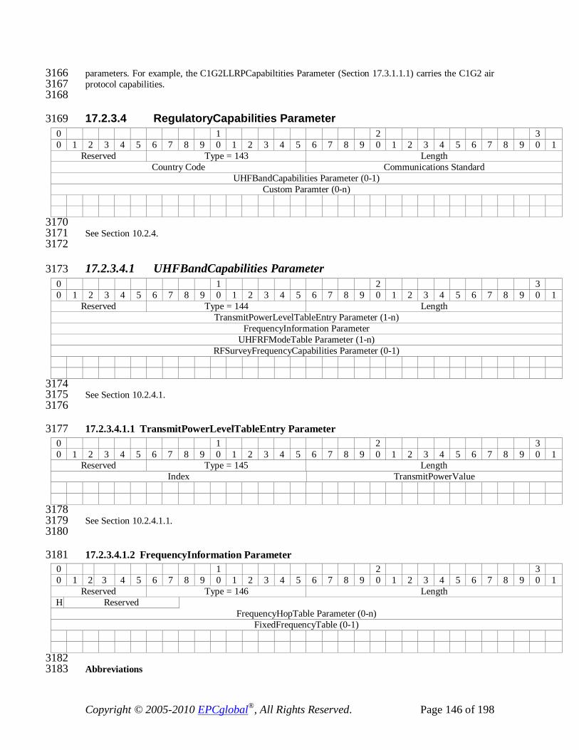
Copyright © 2005-2010 EPCglobal®, All Rights Reserved. Page 146 of 198
parameters. For example, the C1G2LLRPCapabiltities Parameter (Section 17.3.1.1.1) carries the C1G2 air 3166 protocol capabilities. 3167 3168
17.2.3.4 RegulatoryCapabilities Parameter 3169 0 1 2 3 0 1 2 3 4 5 6 7 8 9 0 1 2 3 4 5 6 7 8 9 0 1 2 3 4 5 6 7 8 9 0 1
Reserved Type = 143 Length Country Code Communications Standard
UHFBandCapabilities Parameter (0-1) Custom Paramter (0-n)
3170 See Section 10.2.4. 3171 3172
17.2.3.4.1 UHFBandCapabilities Parameter 3173 0 1 2 3 0 1 2 3 4 5 6 7 8 9 0 1 2 3 4 5 6 7 8 9 0 1 2 3 4 5 6 7 8 9 0 1
Reserved Type = 144 Length TransmitPowerLevelTableEntry Parameter (1-n)
FrequencyInformation Parameter UHFRFModeTable Parameter (1-n)
RFSurveyFrequencyCapabilities Parameter (0-1)
3174 See Section 10.2.4.1. 3175 3176
17.2.3.4.1.1 TransmitPowerLevelTableEntry Parameter 3177 0 1 2 3 0 1 2 3 4 5 6 7 8 9 0 1 2 3 4 5 6 7 8 9 0 1 2 3 4 5 6 7 8 9 0 1
Reserved Type = 145 Length Index TransmitPowerValue
3178 See Section 10.2.4.1.1. 3179 3180
17.2.3.4.1.2 FrequencyInformation Parameter 3181 0 1 2 3 0 1 2 3 4 5 6 7 8 9 0 1 2 3 4 5 6 7 8 9 0 1 2 3 4 5 6 7 8 9 0 1
Reserved Type = 146 Length H Reserved
FrequencyHopTable Parameter (0-n) FixedFrequencyTable (0-1)
3182 Abbreviations 3183

Copyright © 2005-2010 EPCglobal®, All Rights Reserved. Page 147 of 198
H – Hopping 3184 3185
See Section 10.2.4.1.2. 3186 3187
17.2.3.4.1.2.1 FrequencyHopTable Parameter 3188 0 1 2 3 0 1 2 3 4 5 6 7 8 9 0 1 2 3 4 5 6 7 8 9 0 1 2 3 4 5 6 7 8 9 0 1
Reserved Type = 147 Length HopTableId Reserved NumHops
Frequency#1 ….
Frequency#n
3189 NumHops: Number of entries in the List of Frequencies. 3190 3191 See Section 10.2.4.1.2.1. 3192
17.2.3.4.1.2.2 FixedFrequencyTable Parameter 3193 0 1 2 3 0 1 2 3 4 5 6 7 8 9 0 1 2 3 4 5 6 7 8 9 0 1 2 3 4 5 6 7 8 9 0 1
Reserved Type = 148 Length NumFrequencies Frequency#1[31:16]
Frequency#1[15:0] …. ….
Frequency#n [15:0]
NumFrequencies: Number of entries in the List of Frequencies. 3194 3195 See Section 10.2.4.1.2.2. 3196 3197
17.2.3.4.1.3 RFSurveyFrequencyCapabilities Parameter 3198 0 1 2 3 0 1 2 3 4 5 6 7 8 9 0 1 2 3 4 5 6 7 8 9 0 1 2 3 4 5 6 7 8 9 0 1
Reserved Type = 365 Length MinimumFrequency MaximumFrequency
3199 See section 10.2.4.1.3. 3200 3201
17.2.4 Reader Operations Parameters 3202
17.2.4.1 ROSpec Parameter 3203 0 1 2 3 0 1 2 3 4 5 6 7 8 9 0 1 2 3 4 5 6 7 8 9 0 1 2 3 4 5 6 7 8 9 0 1
Reserved Type = 177 Length

Copyright © 2005-2010 EPCglobal®, All Rights Reserved. Page 148 of 198
ROSpecID Priority CurrentState
ROBoundarySpec Parameter SpecParameter (1-n) [See notes below]
ROReportSpec Parameter (0-1)
3204 Notes 3205 Each SpecParameter can be one of the following types: AISpec Parameter or RFSurveySpec Parameter or 3206 LoopSpec Parameter or Custom Parameter. 3207 3208 See Section 11.2.1. 3209 3210
17.2.4.1.1 ROBoundarySpec Parameter 3211 0 1 2 3 0 1 2 3 4 5 6 7 8 9 0 1 2 3 4 5 6 7 8 9 0 1 2 3 4 5 6 7 8 9 0 1
Reserved Type = 178 Length ROSpecStartTrigger Parameter ROSpecStopTrigger Parameter
3212 See Section 11.2.1.1. 3213 3214
17.2.4.1.1.1 ROSpecStartTrigger Parameter 3215 0 1 2 3 0 1 2 3 4 5 6 7 8 9 0 1 2 3 4 5 6 7 8 9 0 1 2 3 4 5 6 7 8 9 0 1
Reserved Type = 179 Length ROSpecStartTriggerType
PeriodicTriggerValue Parameter (0-1) GPITriggerValue Parameter (0-1)
3216 See Section 11.2.1.1.1. 3217 3218
17.2.4.1.1.1.1 PeriodicTriggerValue Parameter 3219 0 1 2 3 0 1 2 3 4 5 6 7 8 9 0 1 2 3 4 5 6 7 8 9 0 1 2 3 4 5 6 7 8 9 0 1
Reserved Type = 180 Length Offset Period
UTCTimestamp Parameter (0-1)
3220 See Section 11.2.1.1.1.1. 3221 3222

Copyright © 2005-2010 EPCglobal®, All Rights Reserved. Page 149 of 198
17.2.4.1.1.1.2 GPITriggerValue Parameter 3223 0 1 2 3 0 1 2 3 4 5 6 7 8 9 0 1 2 3 4 5 6 7 8 9 0 1 2 3 4 5 6 7 8 9 0 1
Reserved Type = 181 Length GPIPortNum E Reserved Timeout[31:24]
Timeout [23:0]
3224 Abbreviations 3225
E – GPIEvent 3226 3227
See section 11.2.1.1.1.2. 3228 3229
17.2.4.1.1.2 ROSpecStopTrigger Parameter 3230 0 1 2 3 0 1 2 3 4 5 6 7 8 9 0 1 2 3 4 5 6 7 8 9 0 1 2 3 4 5 6 7 8 9 0 1
Reserved Type = 182 Length ROSpecStopTriggerType DurationTriggerValue[31:8]
DurationTriggerValue[7:0] GPITriggerValue Parameter (0-1)
3231 See section 11.2.1.1.2. 3232 3233
17.2.4.2 AISpec Parameter 3234 0 1 2 3 0 1 2 3 4 5 6 7 8 9 0 1 2 3 4 5 6 7 8 9 0 1 2 3 4 5 6 7 8 9 0 1
Reserved Type = 183 Length AntennaCount AntennaID#1
…… AntennaID#n AISpecStopTrigger Parameter
InventoryParameter Spec Parameter (1-n) Custom Parameter (0-n)
3235 See section 11.2.2. 3236 3237
17.2.4.2.1 AISpecStopTrigger Parameter 3238 0 1 2 3 0 1 2 3 4 5 6 7 8 9 0 1 2 3 4 5 6 7 8 9 0 1 2 3 4 5 6 7 8 9 0 1
Reserved Type = 184 Length AISpecStopTriggerType DurationTrigger[31:24]
DurationTrigger[7:0] GPITriggerValue Parameter (0-1)
TagObservationTrigger Parameter (0-1)
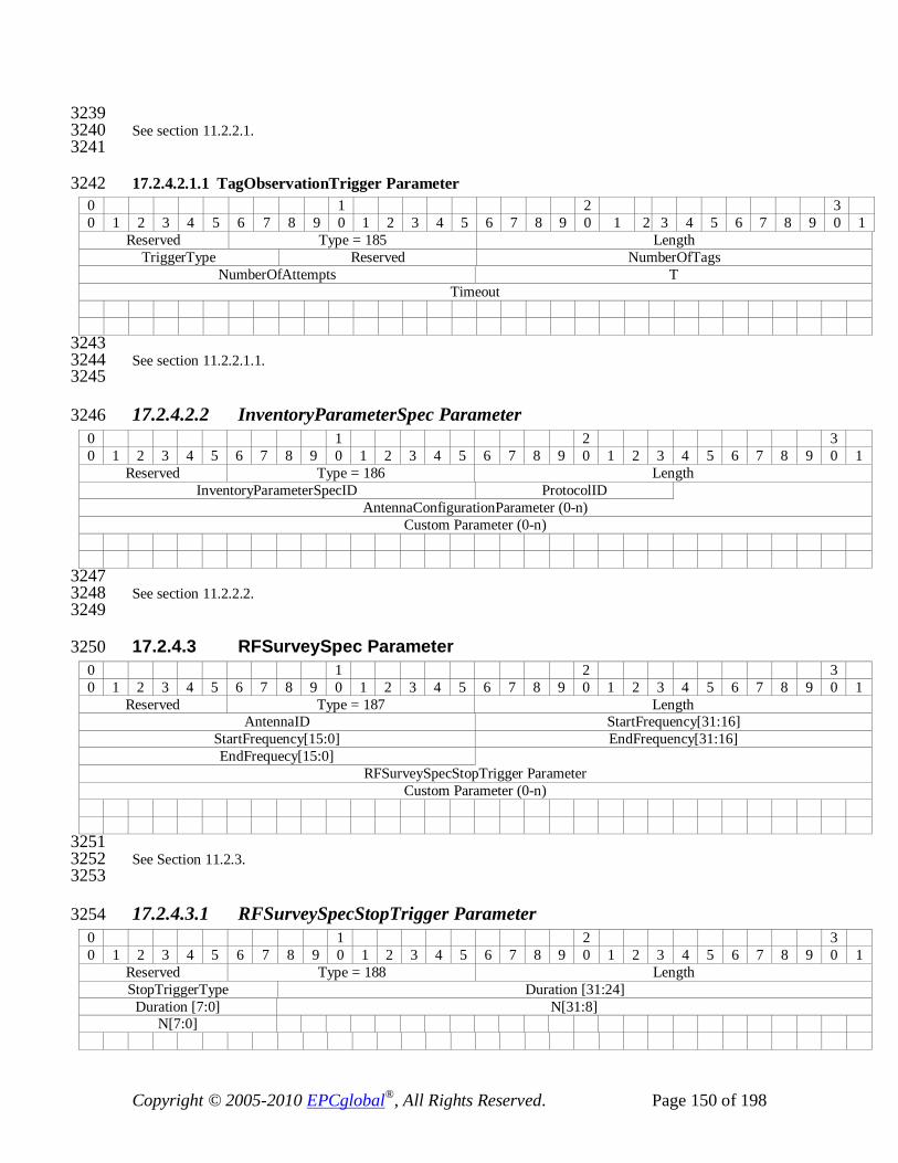
Copyright © 2005-2010 EPCglobal®, All Rights Reserved. Page 150 of 198
3239 See section 11.2.2.1. 3240 3241
17.2.4.2.1.1 TagObservationTrigger Parameter 3242 0 1 2 3 0 1 2 3 4 5 6 7 8 9 0 1 2 3 4 5 6 7 8 9 0 1 2 3 4 5 6 7 8 9 0 1
Reserved Type = 185 Length TriggerType Reserved NumberOfTags
NumberOfAttempts T Timeout
3243 See section 11.2.2.1.1. 3244 3245
17.2.4.2.2 InventoryParameterSpec Parameter 3246 0 1 2 3 0 1 2 3 4 5 6 7 8 9 0 1 2 3 4 5 6 7 8 9 0 1 2 3 4 5 6 7 8 9 0 1
Reserved Type = 186 Length InventoryParameterSpecID ProtocolID
AntennaConfigurationParameter (0-n) Custom Parameter (0-n)
3247 See section 11.2.2.2. 3248 3249
17.2.4.3 RFSurveySpec Parameter 3250 0 1 2 3 0 1 2 3 4 5 6 7 8 9 0 1 2 3 4 5 6 7 8 9 0 1 2 3 4 5 6 7 8 9 0 1
Reserved Type = 187 Length AntennaID StartFrequency[31:16]
StartFrequency[15:0] EndFrequency[31:16] EndFrequecy[15:0]
RFSurveySpecStopTrigger Parameter Custom Parameter (0-n)
3251 See Section 11.2.3. 3252 3253
17.2.4.3.1 RFSurveySpecStopTrigger Parameter 3254 0 1 2 3 0 1 2 3 4 5 6 7 8 9 0 1 2 3 4 5 6 7 8 9 0 1 2 3 4 5 6 7 8 9 0 1
Reserved Type = 188 Length StopTriggerType Duration [31:24]
Duration [7:0] N[31:8] N[7:0]

Copyright © 2005-2010 EPCglobal®, All Rights Reserved. Page 151 of 198
3255 See Section 11.2.3.1. 3256 3257
17.2.4.4 LoopSpec Parameter 3258 0 1 2 3 0 1 2 3 4 5 6 7 8 9 0 1 2 3 4 5 6 7 8 9 0 1 2 3 4 5 6 7 8 9 0 1
Reserved Type = 355 Length LoopCount
3259 See Section 11.2.4. 3260
17.2.5 Access Operation Parameters 3261
17.2.5.1 AccessSpec Parameter 3262 0 1 2 3 0 1 2 3 4 5 6 7 8 9 0 1 2 3 4 5 6 7 8 9 0 1 2 3 4 5 6 7 8 9 0 1
Reserved Type = 207 Length AccessSpecID
AntennaId ProtocolId C Reserved ROSpecID
AccessSpecStopTrigger Parameter AccessCommand Parameter
AccessReportSpec Parameter (0-1) Custom Parameter (0-n)
Abbreviations 3263 C – CurrentState 3264
3265 See section 12.2.1. 3266 3267
17.2.5.1.1 AccessSpecStopTrigger Parameter 3268 0 1 2 3 0 1 2 3 4 5 6 7 8 9 0 1 2 3 4 5 6 7 8 9 0 1 2 3 4 5 6 7 8 9 0 1
Reserved Type = 208 Length AccessSpecStopTrigger OperationCountValue
3269 See Section 12.2.1.1. 3270 3271
17.2.5.1.2 AccessCommand Parameter 3272 0 1 2 3 0 1 2 3 4 5 6 7 8 9 0 1 2 3 4 5 6 7 8 9 0 1 2 3 4 5 6 7 8 9 0 1
Reserved Type = 209 Length TagSpecParameter [See notes below]
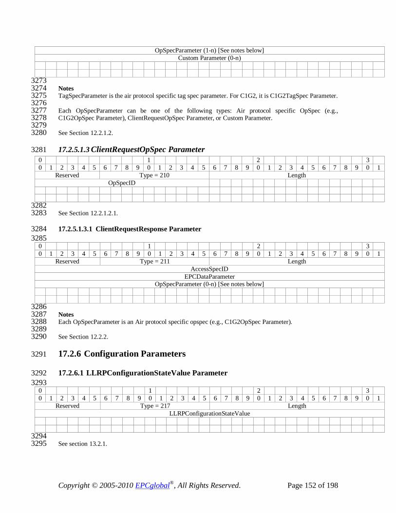
Copyright © 2005-2010 EPCglobal®, All Rights Reserved. Page 152 of 198
OpSpecParameter (1-n) [See notes below] Custom Parameter (0-n)
3273 Notes 3274 TagSpecParameter is the air protocol specific tag spec parameter. For C1G2, it is C1G2TagSpec Parameter. 3275 3276 Each OpSpecParameter can be one of the following types: Air protocol specific OpSpec (e.g., 3277 C1G2OpSpec Parameter), ClientRequestOpSpec Parameter, or Custom Parameter. 3278 3279 See Section 12.2.1.2. 3280
17.2.5.1.3 ClientRequestOpSpec Parameter 3281 0 1 2 3 0 1 2 3 4 5 6 7 8 9 0 1 2 3 4 5 6 7 8 9 0 1 2 3 4 5 6 7 8 9 0 1
Reserved Type = 210 Length OpSpecID
3282 See Section 12.2.1.2.1. 3283
17.2.5.1.3.1 ClientRequestResponse Parameter 3284 3285
0 1 2 3 0 1 2 3 4 5 6 7 8 9 0 1 2 3 4 5 6 7 8 9 0 1 2 3 4 5 6 7 8 9 0 1
Reserved Type = 211 Length AccessSpecID
EPCDataParameter OpSpecParameter (0-n) [See notes below]
3286 Notes 3287 Each OpSpecParameter is an Air protocol specific opspec (e.g., C1G2OpSpec Parameter). 3288 3289 See Section 12.2.2. 3290
17.2.6 Configuration Parameters 3291
17.2.6.1 LLRPConfigurationStateValue Parameter 3292 3293
0 1 2 3 0 1 2 3 4 5 6 7 8 9 0 1 2 3 4 5 6 7 8 9 0 1 2 3 4 5 6 7 8 9 0 1
Reserved Type = 217 Length LLRPConfigurationStateValue
3294 See section 13.2.1. 3295

Copyright © 2005-2010 EPCglobal®, All Rights Reserved. Page 153 of 198
17.2.6.2 Identification Parameter 3296 0 1 2 3 0 1 2 3 4 5 6 7 8 9 0 1 2 3 4 5 6 7 8 9 0 1 2 3 4 5 6 7 8 9 0 1
Reserved Type = 218 Length IDType ByteCount
Reader ID(Variable length)
3297 See Section 13.2.2. 3298
17.2.6.3 GPOWriteData Parameter 3299 0 1 2 3 0 1 2 3 4 5 6 7 8 9 0 1 2 3 4 5 6 7 8 9 0 1 2 3 4 5 6 7 8 9 0 1
Reserved Type = 219 Length GPO Port Number W Reserved
3300 Abbreviations 3301
W – GPO Data 3302 3303
See Section 13.2.3. 3304
17.2.6.4 KeepaliveSpec Parameter 3305 0 1 2 3 0 1 2 3 4 5 6 7 8 9 0 1 2 3 4 5 6 7 8 9 0 1 2 3 4 5 6 7 8 9 0 1
Reserved Type = 220 Length KeepaliveTriggerType TimeInterval
TimeInterval
3306 See Section 13.2.4. 3307
17.2.6.5 AntennaProperties Parameter 3308 0 1 2 3 0 1 2 3 4 5 6 7 8 9 0 1 2 3 4 5 6 7 8 9 0 1 2 3 4 5 6 7 8 9 0 1
Reserved Type = 221 Length C Reserved AntennaId AntennaGain[15:8]
AntennaGain[7:0]
3309 Abbreviations 3310
C – Antenna connected 3311 3312 See Section 13.2.5. 3313 3314

Copyright © 2005-2010 EPCglobal®, All Rights Reserved. Page 154 of 198
17.2.6.6 AntennaConfiguration Parameter 3315 0 1 2 3 0 1 2 3 4 5 6 7 8 9 0 1 2 3 4 5 6 7 8 9 0 1 2 3 4 5 6 7 8 9 0 1
Reserved Type = 222 Length AntennaId
RFReceiver Parameter (0-1) RFTransmitter Parameter (0-1)
AirProtocolInventoryCommandSettings Parameter (0-n) Custom Parameter (0-n)
3316 Notes: 3317 Each AirProtocolInventoryCommandSettingsParameter instance is an Air protocol specific Parameter (e.g., 3318 C1G2InventoryCommand Parameter). 3319 3320 See Section 13.2.6. 3321 3322
17.2.6.7 RFReceiver Parameter 3323 0 1 2 3 0 1 2 3 4 5 6 7 8 9 0 1 2 3 4 5 6 7 8 9 0 1 2 3 4 5 6 7 8 9 0 1
Reserved Type = 223 Length Receiver Sensitivity
3324 See Section 13.2.6.1. 3325 3326
17.2.6.8 RFTransmitter Parameter 3327 0 1 2 3 0 1 2 3 4 5 6 7 8 9 0 1 2 3 4 5 6 7 8 9 0 1 2 3 4 5 6 7 8 9 0 1
Reserved Type = 224 Length HopTableId ChannelIndex
TransmitPower
3328 See Section 13.2.6.2. 3329 3330
17.2.6.9 GPIPortCurrentState Parameter 3331 0 1 2 3 0 1 2 3 4 5 6 7 8 9 0 1 2 3 4 5 6 7 8 9 0 1 2 3 4 5 6 7 8 9 0 1
Reserved Type = 225 Length GPIPortNum C Reserved GPIState
3332 3333 Abbreviations 3334 C – GPIConfig 3335

Copyright © 2005-2010 EPCglobal®, All Rights Reserved. Page 155 of 198
3336 See Section 13.2.6.3. 3337 3338
17.2.6.10 EventsAndReports Parameter 3339 0 1 2 3 0 1 2 3 4 5 6 7 8 9 0 1 2 3 4 5 6 7 8 9 0 1 2 3 4 5 6 7 8 9 0 1
Reserved Type = 226 Length H Reserved
3340 Abbreviations 3341 H – HoldEventsAndReportsUponReconnect 3342 3343 See Section 13.2.6.4 3344 3345
17.2.7 Reporting Parameters 3346
17.2.7.1 ROReportSpec Parameter 3347 0 1 2 3 0 1 2 3 4 5 6 7 8 9 0 1 2 3 4 5 6 7 8 9 0 1 2 3 4 5 6 7 8 9 0 1
Reserved Type = 237 Length ROReportTrigger N
TagReportContentSelector Parameter Custom Parameter (0-n)
3348 See Section 14.2.1. 3349 3350
17.2.7.1.1 TagReportContentSelector Parameter 3351 0 1 2 3 0 1 2 3 4 5 6 7 8 9 0 1 2 3 4 5 6 7 8 9 0 1 2 3 4 5 6 7 8 9 0 1
Reserved Type = 238 Length R I P A C R F L T S Reserved
AirProtocolSpecificEPCMemorySelectorParameter (0-n) [See notes below] Custom Parameter (0-n)
Abbreviations 3352 3353 R – EnableROSpecID 3354 I – EnableSpecIndex 3355 P – EnableInventoryParameterSpecID 3356 A – EnableAntennaID 3357 C – EnableChannelIndex 3358 R – EnablePeakRSSI 3359 F – EnableFirstSeenTimestamp 3360 L – EnableLastSeenTimestamp 3361 T – EnableTagSeenCount 3362

Copyright © 2005-2010 EPCglobal®, All Rights Reserved. Page 156 of 198
S – EnableAccessSpecID 3363 3364 Notes: 3365 Each instance of AirProtocolSpecificEPCMemorySelectorParameter is one of the air protocol specific 3366 selector parameters (e.g., C1G2EPCMemorySelector Parameter). 3367 3368 See section 14.2.1.1. 3369 3370
17.2.7.2 AccessReportSpec Parameter 3371 0 1 2 3 0 1 2 3 4 5 6 7 8 9 0 1 2 3 4 5 6 7 8 9 0 1 2 3 4 5 6 7 8 9 0 1
Reserved Type = 239 Length AccessReportTrigger
3372 See section 14.2.2. 3373
17.2.7.3 TagReportData Parameter 3374 0 1 2 3 0 1 2 3 4 5 6 7 8 9 0 1 2 3 4 5 6 7 8 9 0 1 2 3 4 5 6 7 8 9 0 1
Reserved Type = 240 Length EPCDataParameter [See notes below]
ROSpecID Parameter (0-1) SpecIndex Parameter (0-1)
InventoryParameterSpecID Parameter (0-1) AntennaID Parameter (0-1) PeakRSSI Parameter (0-1)
ChannelIndex Parameter (0-1) FirstSeenTimestampUTC Parameter (0-1)
FirstSeenTimestampUptime Parameter (0-1) LastSeenTimestampUTC Parameter (0-1)
LastSeenTimestampUptime Parameter (0-1) TagSeenCount Parameter (0-1)
AirProtocolTagDataParameter (0-n)[See Notes below] AccessSpecID Parameter (0-1)
OpSpecResultParameter (0-n) [See notes below] Custom Parameter (0-n)
3375 Notes: 3376 The EPCDataParameter is either the EPCData Parameter (Section 17.2.7.3.1) or EPC-96 Parameter 3377 (Section 17.2.7.3.2). The EPCData Parameter SHALL be used for encoding a non-96 bit EPC, whereas the 3378 EPC-96 Parameter SHALL be used for encoding a 96-bit EPC. 3379 3380 The AirProtocolTagDataParameter is one or more air protocol specific tag data parameters (e.g., C1G2PC, 3381 C1G2XPCW1, C1G2XPCW2, and C1G2CRC). In the C1G2 case, each parameter, C1G2PC, 3382 C1G2XPCW1, C1G2XPCW2, and C1G2CRC, is optional in the TagReportData Parameter. 3383 3384 OpSpecResultParameter: Either an air protocol specific OpSpec result parameter (e.g., C1G2OpSpecResult 3385 Parameter), a ClientRequestOpSpecResult Parameter, or a Custom Parameter. 3386

Copyright © 2005-2010 EPCglobal®, All Rights Reserved. Page 157 of 198
3387 See section 14.2.3. 3388
17.2.7.3.1 EPCData Parameter 3389 0 1 2 3 0 1 2 3 4 5 6 7 8 9 0 1 2 3 4 5 6 7 8 9 0 1 2 3 4 5 6 7 8 9 0 1
Reserved Type = 241 Length EPCLengthBits
EPC
3390 EPCLengthBits: Number of bits in the EPC. 3391 See Section 14.2.3.2. 3392 3393
17.2.7.3.2 EPC-96 Parameter (TV-Encoding) 3394 0 1 2 3 0 1 2 3 4 5 6 7 8 9 0 1 2 3 4 5 6 7 8 9 0 1 2 3 4 5 6 7 8 9 0 1 1 Type=13 EPC[95:72]
EPC[71:40] EPC[39:8]
EPC[7:0] 3395 See Section 14.2.3.2. 3396
17.2.7.3.3 ROSpecID Parameter (TV-Encoding) 3397 0 1 2 3 0 1 2 3 4 5 6 7 8 9 0 1 2 3 4 5 6 7 8 9 0 1 2 3 4 5 6 7 8 9 0 1 1 Type=9 ROSpecID[31:8]
ROSpecID[7:0] 3398 See Section 14.2.3.3. 3399 3400
17.2.7.3.4 SpecIndex Parameter (TV-Encoding) 3401 0 1 2 3 0 1 2 3 4 5 6 7 8 9 0 1 2 3 4 5 6 7 8 9 0 1 2 3 4 5 6 7 8 9 0 1 1 Type=14 SpecIndex
3402 See Section 14.2.3.4. 3403
17.2.7.3.5 InventoryParameterSpecID Parameter (TV-Encoding) 3404 0 1 2 3 0 1 2 3 4 5 6 7 8 9 0 1 2 3 4 5 6 7 8 9 0 1 2 3 4 5 6 7 8 9 0 1 1 Type=10 InventoryParameterSpecId
3405 See Section 14.2.3.5. 3406

Copyright © 2005-2010 EPCglobal®, All Rights Reserved. Page 158 of 198
17.2.7.3.6 AntennaID Parameter (TV-Encoding) 3407 0 1 2 3 0 1 2 3 4 5 6 7 8 9 0 1 2 3 4 5 6 7 8 9 0 1 2 3 4 5 6 7 8 9 0 1 1 Type=1 AntennaId
3408 See Section 14.2.3.6. 3409
17.2.7.3.7 PeakRSSI Parameter (TV-Encoding) 3410 0 1 2 3 0 1 2 3 4 5 6 7 8 9 0 1 2 3 4 5 6 7 8 9 0 1 2 3 4 5 6 7 8 9 0 1 1 Type=6 PeakRSSI
3411 See Section 14.2.3.7. 3412
17.2.7.3.8 ChannelIndex Parameter (TV-Encoding) 3413 0 1 2 3 0 1 2 3 4 5 6 7 8 9 0 1 2 3 4 5 6 7 8 9 0 1 2 3 4 5 6 7 8 9 0 1 1 Type=7 ChannelIndex
3414 See Section 14.2.3.8. 3415
17.2.7.3.9 FirstSeenTimestampUTC Parameter (TV-Encoding) 3416 0 1 2 3 0 1 2 3 4 5 6 7 8 9 0 1 2 3 4 5 6 7 8 9 0 1 2 3 4 5 6 7 8 9 0 1 1 Type=2 Microseconds [63:40]
Microseconds [39:8] Microseconds[7:0]
3417 See Section 14.2.3.9. 3418
17.2.7.3.10 FirstSeenTimestampUptime Parameter (TV-Encoding) 3419 0 1 2 3 0 1 2 3 4 5 6 7 8 9 0 1 2 3 4 5 6 7 8 9 0 1 2 3 4 5 6 7 8 9 0 1 1 Type=3 Microseconds[63:40]
Microseconds [39:8] Microseconds[7:0]
3420 See Section 14.2.3.10. 3421
17.2.7.3.11 LastSeenTimestampUTC Parameter (TV-Encoding) 3422 0 1 2 3 0 1 2 3 4 5 6 7 8 9 0 1 2 3 4 5 6 7 8 9 0 1 2 3 4 5 6 7 8 9 0 1 1 Type=4 Microseconds[63:40]
Microseconds[39:8] Microseconds[7:0]
3423

Copyright © 2005-2010 EPCglobal®, All Rights Reserved. Page 159 of 198
See Section 14.2.3.11. 3424
17.2.7.3.12 LastSeenTimestampUptime Parameter (TV-Encoding) 3425 0 1 2 3 0 1 2 3 4 5 6 7 8 9 0 1 2 3 4 5 6 7 8 9 0 1 2 3 4 5 6 7 8 9 0 1 1 Type=5 Microseconds[63:40]
Microseconds[39:8] Microseconds[7:0]
3426 See Section 14.2.3.12. 3427
17.2.7.3.13 TagSeenCount Parameter (TV-Encoding) 3428 0 1 2 3 0 1 2 3 4 5 6 7 8 9 0 1 2 3 4 5 6 7 8 9 0 1 2 3 4 5 6 7 8 9 0 1 1 Type=8 TagCount
3429 See Section 14.2.3.13. 3430
17.2.7.3.14 ClientRequestOpSpecResult Parameter (TV-Encoding) 3431 0 1 2 3 0 1 2 3 4 5 6 7 8 9 0 1 2 3 4 5 6 7 8 9 0 1 2 3 4 5 6 7 8 9 0 1 1 Type=15 OpSpecID
3432 See Section 14.2.3.14. 3433
17.2.7.3.15 AccessSpecID Parameter (TV-Encoding) 3434 0 1 2 3 0 1 2 3 4 5 6 7 8 9 0 1 2 3 4 5 6 7 8 9 0 1 2 3 4 5 6 7 8 9 0 1 1 Type=16 AccessSpecID[31:8]
AccessSpecID[7:0] 3435 See Section 14.2.3.15. 3436 3437 3438
17.2.7.4 RFSurveyReportData Parameter 3439 3440
0 1 2 3 0 1 2 3 4 5 6 7 8 9 0 1 2 3 4 5 6 7 8 9 0 1 2 3 4 5 6 7 8 9 0 1
Reserved Type = 242 Length ROSpecID Parameter (0-1) SpecIndex Parameter (0-1)
FrequencyRSSILevelEntry Parameter (1-n) Custom Parameter (0-n)
3441
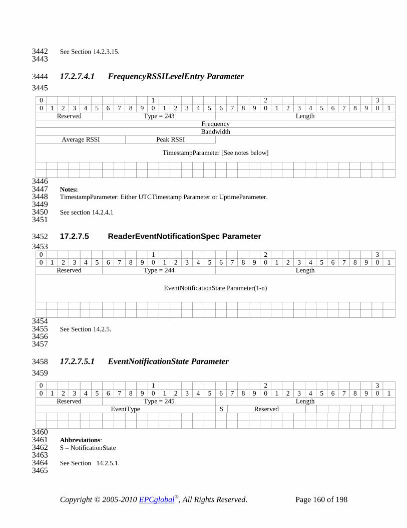
Copyright © 2005-2010 EPCglobal®, All Rights Reserved. Page 160 of 198
See Section 14.2.3.15. 3442 3443
17.2.7.4.1 FrequencyRSSILevelEntry Parameter 3444 3445
0 1 2 3 0 1 2 3 4 5 6 7 8 9 0 1 2 3 4 5 6 7 8 9 0 1 2 3 4 5 6 7 8 9 0 1
Reserved Type = 243 Length Frequency Bandwidth
Average RSSI Peak RSSI
TimestampParameter [See notes below]
3446 Notes: 3447 TimestampParameter: Either UTCTimestamp Parameter or UptimeParameter. 3448 3449 See section 14.2.4.1 3450 3451
17.2.7.5 ReaderEventNotificationSpec Parameter 3452 3453
0 1 2 3 0 1 2 3 4 5 6 7 8 9 0 1 2 3 4 5 6 7 8 9 0 1 2 3 4 5 6 7 8 9 0 1
Reserved Type = 244 Length
EventNotificationState Parameter(1-n)
3454 See Section 14.2.5. 3455 3456 3457
17.2.7.5.1 EventNotificationState Parameter 3458 3459
0 1 2 3 0 1 2 3 4 5 6 7 8 9 0 1 2 3 4 5 6 7 8 9 0 1 2 3 4 5 6 7 8 9 0 1
Reserved Type = 245 Length EventType S Reserved
3460 Abbreviations: 3461 S – NotificationState 3462 3463 See Section 14.2.5.1. 3464 3465

Copyright © 2005-2010 EPCglobal®, All Rights Reserved. Page 161 of 198
17.2.7.6 ReaderEventNotificationData Parameter 3466 0 1 2 3 0 1 2 3 4 5 6 7 8 9 0 1 2 3 4 5 6 7 8 9 0 1 2 3 4 5 6 7 8 9 0 1
Reserved Type = 246 Length TimestampParameter [See notes below]
HoppingEvent Parameter (0-1) GPIEvent Parameter (0-1)
ROSpecEvent Parameter (0-1) ReportBufferLevelWarningEvent Parameter (0-1) ReportBufferOverflowErrorEvent Parameter (0-1)
ReaderExceptionEvent Parameter (0-1) RFSurveyEvent Parameter (0-1)
AISpecEvent Parameter (0-1) AntennaEvent Parameter (0-1)
ConnectionAttemptEvent Parameter (0-1) ConnectionCloseEvent Parameter (0-1)
SpecLoopEvent Parameter (0-1) Custom Parameter (0-n)
3467 Notes: 3468 TimestampParameter: Either UTCTimestamp Parameter or Uptime Parameter. 3469 3470 See section 14.2.6. 3471 3472
17.2.7.6.1 HoppingEvent Parameter 3473 0 1 2 3 0 1 2 3 4 5 6 7 8 9 0 1 2 3 4 5 6 7 8 9 0 1 2 3 4 5 6 7 8 9 0 1
Reserved Type = 247 Length HopTableID NextChannelIndex
3474 See section 14.2.6.2. 3475 3476
17.2.7.6.2 GPIEvent Parameter 3477 0 1 2 3 0 1 2 3 4 5 6 7 8 9 0 1 2 3 4 5 6 7 8 9 0 1 2 3 4 5 6 7 8 9 0 1
Reserved Type = 248 Length GPIPortNumber E Reserved
Abbreviations 3478 E – GPIEvent 3479 3480
See section 14.2.6.3. 3481 3482
17.2.7.6.3 ROSpecEvent Parameter 3483 0 1 2 3
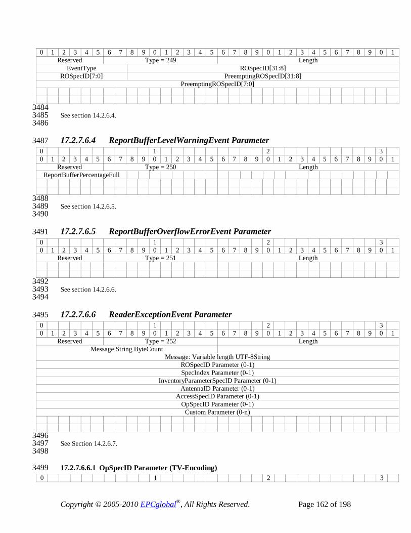
Copyright © 2005-2010 EPCglobal®, All Rights Reserved. Page 162 of 198
0 1 2 3 4 5 6 7 8 9 0 1 2 3 4 5 6 7 8 9 0 1 2 3 4 5 6 7 8 9 0 1 Reserved Type = 249 Length
EventType ROSpecID[31:8] ROSpecID[7:0] PreemptingROSpecID[31:8]
PreemptingROSpecID[7:0]
3484 See section 14.2.6.4. 3485 3486
17.2.7.6.4 ReportBufferLevelWarningEvent Parameter 3487 0 1 2 3 0 1 2 3 4 5 6 7 8 9 0 1 2 3 4 5 6 7 8 9 0 1 2 3 4 5 6 7 8 9 0 1
Reserved Type = 250 Length ReportBufferPercentageFull
3488 See section 14.2.6.5. 3489 3490
17.2.7.6.5 ReportBufferOverflowErrorEvent Parameter 3491 0 1 2 3 0 1 2 3 4 5 6 7 8 9 0 1 2 3 4 5 6 7 8 9 0 1 2 3 4 5 6 7 8 9 0 1
Reserved Type = 251 Length
3492 See section 14.2.6.6. 3493 3494
17.2.7.6.6 ReaderExceptionEvent Parameter 3495 0 1 2 3 0 1 2 3 4 5 6 7 8 9 0 1 2 3 4 5 6 7 8 9 0 1 2 3 4 5 6 7 8 9 0 1
Reserved Type = 252 Length Message String ByteCount
Message: Variable length UTF-8String ROSpecID Parameter (0-1) SpecIndex Parameter (0-1)
InventoryParameterSpecID Parameter (0-1) AntennaID Parameter (0-1)
AccessSpecID Parameter (0-1) OpSpecID Parameter (0-1)
Custom Parameter (0-n)
3496 See Section 14.2.6.7. 3497 3498
17.2.7.6.6.1 OpSpecID Parameter (TV-Encoding) 3499 0 1 2 3

Copyright © 2005-2010 EPCglobal®, All Rights Reserved. Page 163 of 198
0 1 2 3 4 5 6 7 8 9 0 1 2 3 4 5 6 7 8 9 0 1 2 3 4 5 6 7 8 9 0 1 1 Type=17 OpSpecID
3500 See Section 13.2.5.7.1. 3501
17.2.7.6.7 RFSurveyEvent Parameter 3502 0 1 2 3 0 1 2 3 4 5 6 7 8 9 0 1 2 3 4 5 6 7 8 9 0 1 2 3 4 5 6 7 8 9 0 1
Reserved Type = 253 Length EventType ROSpecID[31:8]
ROSpecID[7:0] SpecIndex[15:0]
3503 See Section 14.2.6.7.1. 3504 3505 3506
17.2.7.6.8 AISpecEvent Parameter 3507 0 1 2 3 0 1 2 3 4 5 6 7 8 9 0 1 2 3 4 5 6 7 8 9 0 1 2 3 4 5 6 7 8 9 0 1
Reserved Type = 254 Length EventType ROSpecID[31:8]
ROSpecID[7:0] SpecIndex[15:0] AirProtocolSingulationDetailsParameter (0-1) [See notes below]
3508 See section 14.2.6.9. 3509 Notes: 3510 3511 AirProtocolSingulationDetailsParameter is one of the air protocol specific singulation parameters (e.g., 3512 C1G2SingulationDetails Parameter). 3513 3514
17.2.7.6.9 AntennaEvent Parameter 3515 0 1 2 3 0 1 2 3 4 5 6 7 8 9 0 1 2 3 4 5 6 7 8 9 0 1 2 3 4 5 6 7 8 9 0 1
Reserved Type = 255 Length EventType AntennaID
3516 See Section 14.2.6.10. 3517 3518
17.2.7.6.10 ConnectionAttemptEvent Parameter 3519 0 1 2 3 0 1 2 3 4 5 6 7 8 9 0 1 2 3 4 5 6 7 8 9 0 1 2 3 4 5 6 7 8 9 0 1
Reserved Type = 256 Length Status

Copyright © 2005-2010 EPCglobal®, All Rights Reserved. Page 164 of 198
3520 See Section 14.2.6.11. 3521 3522
17.2.7.6.11 ConnectionCloseEvent Parameter 3523 0 1 2 3 0 1 2 3 4 5 6 7 8 9 0 1 2 3 4 5 6 7 8 9 0 1 2 3 4 5 6 7 8 9 0 1
Reserved Type = 257 Length
3524 See Section 14.2.6.12. 3525 3526
17.2.7.6.12 SpecLoopEvent Parameter 3527 0 1 2 3 0 1 2 3 4 5 6 7 8 9 0 1 2 3 4 5 6 7 8 9 0 1 2 3 4 5 6 7 8 9 0 1
Reserved Type = 356 Length ROSpecID LoopCount
3528 See Section 14.2.6.13. 3529
17.2.8 LLRP Error Parameters 3530
17.2.8.1 LLRPStatus Parameter 3531 3532
0 1 2 3 0 1 2 3 4 5 6 7 8 9 0 1 2 3 4 5 6 7 8 9 0 1 2 3 4 5 6 7 8 9 0 1
Reserved Type = 287 Length StatusCode Error Description ByteCount
Error Description: Variable length UTF-8 String FieldError Parameter (0-1)
ParameterError Parameter (0-1)
3533 See Section 15.2.2. 3534 3535
17.2.8.1.1 FieldError Parameter 3536 3537
0 1 2 3 0 1 2 3 4 5 6 7 8 9 0 1 2 3 4 5 6 7 8 9 0 1 2 3 4 5 6 7 8 9 0 1
Reserved Type = 288 Length FieldNum ErrorCode

Copyright © 2005-2010 EPCglobal®, All Rights Reserved. Page 165 of 198
3538 See section 15.2.2.1. 3539 3540
17.2.8.1.2 ParameterError Parameter 3541 3542
0 1 2 3 0 1 2 3 4 5 6 7 8 9 0 1 2 3 4 5 6 7 8 9 0 1 2 3 4 5 6 7 8 9 0 1
Reserved Type = 289 Length ParameterType ErrorCode
Field Error Parameter (0-1) Parameter Error Parameter (0-1)
3543 See Section 15.2.2.2. 3544 3545
17.2.9 Custom Parameter 3546 0 1 2 3 0 1 2 3 4 5 6 7 8 9 0 1 2 3 4 5 6 7 8 9 0 1 2 3 4 5 6 7 8 9 0 1
Reserved Type=1023 Parameter Length Vendor ID
Subtype
VendorParameter Value
3547 See Section 8.2. 3548 3549
17.3 Air Protocol Specific Parameters 3550 This section defines air protocol specific parameter encodings. There is a separate 3551 subsection here for each air protocol defined by LLRP. See section 16, in the LLRP 3552 abstract specification, for more information regarding air protocol specific parameters. 3553
17.3.1 Class-1 Generation-2 (C1G2) Protocol Parameters 3554 The Class-1 Generation-2 (C1G2) Air Protocol is specified by the EPCglobal Class-1 3555 Generation-2 UHF RFID Protocol v1.1.0 specification. 3556 The following subsections specify LLRP air protocol specific parameter encodings. 3557 These subsections are partitioned to correlate with subsections of section 17.2: 3558
- Capabilities Parameters 3559
- Reader Operations Parameters 3560 - Access Operation Parameters 3561
- Configuration Parameters 3562

Copyright © 2005-2010 EPCglobal®, All Rights Reserved. Page 166 of 198
- Reporting Parameters 3563
17.3.1.1 Capabilities Parameters 3564 This section of air protocol specific parameters corresponds to LLRP parameters 3565 encodings specified in section 16.2.1.1. 3566
17.3.1.1.1 C1G2LLRPCapabilities Parameter 3567 0 1 2 3 0 1 2 3 4 5 6 7 8 9 0 1 2 3 4 5 6 7 8 9 0 1 2 3 4 5 6 7 8 9 0 1
Reserved Type =327 Length E W P R U X Rsvd MaxNumSelectFiltersPerQuery
3568 Abbreviations 3569
E – CanSupportBlockErase 3570 W – CanSupportBlockWrite 3571 P – CanSupportBlockPermalock 3572 R – CanSupportTagRecommissioning 3573 U – CanSupportUMIMethod2 3574 X – CanSupportXPC 3575 3576
See Section 16.2.1.1.1. 3577 3578
17.3.1.1.2 UHFC1G2RFModeTable Parameter 3579 0 1 2 3 0 1 2 3 4 5 6 7 8 9 0 1 2 3 4 5 6 7 8 9 0 1 2 3 4 5 6 7 8 9 0 1
Reserved Type = 328 Length UHFC1G2RFModeTableEntry Parameter (1-n)
3580 See Section 16.2.1.1.2. 3581 3582
17.3.1.1.2.1 UHFC1G2RFModeTableEntry Parameter 3583 0 1 2 3 0 1 2 3 4 5 6 7 8 9 0 1 2 3 4 5 6 7 8 9 0 1 2 3 4 5 6 7 8 9 0 1
Reserved Type = 329 Length Mode identifier
R C Reserved Mod FLM M BDR Value PIE Value
MinTariValue MaxTariValue StepTariValue
3584 Abbreviations 3585
R – DR Value 3586
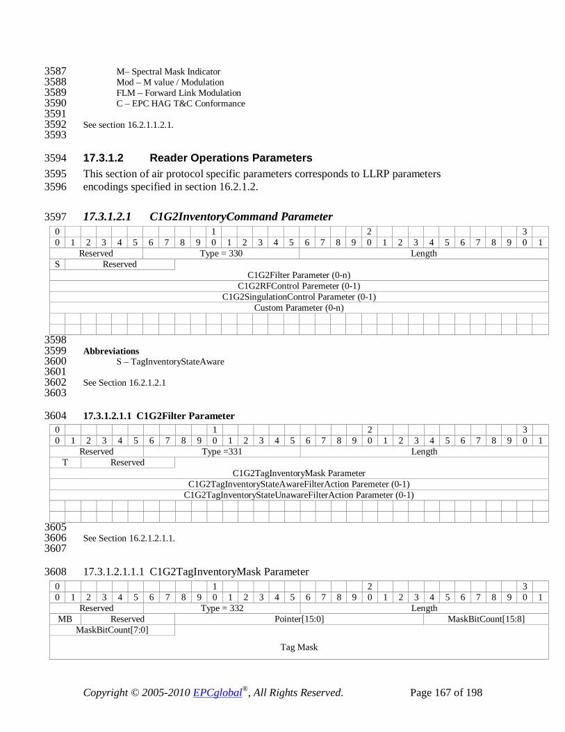
Copyright © 2005-2010 EPCglobal®, All Rights Reserved. Page 167 of 198
M– Spectral Mask Indicator 3587 Mod – M value / Modulation 3588 FLM – Forward Link Modulation 3589 C – EPC HAG T&C Conformance 3590 3591
See section 16.2.1.1.2.1. 3592 3593
17.3.1.2 Reader Operations Parameters 3594 This section of air protocol specific parameters corresponds to LLRP parameters 3595 encodings specified in section 16.2.1.2. 3596
17.3.1.2.1 C1G2InventoryCommand Parameter 3597 0 1 2 3 0 1 2 3 4 5 6 7 8 9 0 1 2 3 4 5 6 7 8 9 0 1 2 3 4 5 6 7 8 9 0 1
Reserved Type = 330 Length S Reserved
C1G2Filter Parameter (0-n) C1G2RFControl Paremeter (0-1)
C1G2SingulationControl Parameter (0-1) Custom Parameter (0-n)
3598 Abbreviations 3599
S – TagInventoryStateAware 3600 3601
See Section 16.2.1.2.1 3602 3603
17.3.1.2.1.1 C1G2Filter Parameter 3604 0 1 2 3 0 1 2 3 4 5 6 7 8 9 0 1 2 3 4 5 6 7 8 9 0 1 2 3 4 5 6 7 8 9 0 1
Reserved Type =331 Length T Reserved
C1G2TagInventoryMask Parameter C1G2TagInventoryStateAwareFilterAction Paremeter (0-1)
C1G2TagInventoryStateUnawareFilterAction Parameter (0-1)
3605 See Section 16.2.1.2.1.1. 3606 3607
17.3.1.2.1.1.1 C1G2TagInventoryMask Parameter 3608 0 1 2 3 0 1 2 3 4 5 6 7 8 9 0 1 2 3 4 5 6 7 8 9 0 1 2 3 4 5 6 7 8 9 0 1
Reserved Type = 332 Length MB Reserved Pointer[15:0] MaskBitCount[15:8]
MaskBitCount[7:0]
Tag Mask
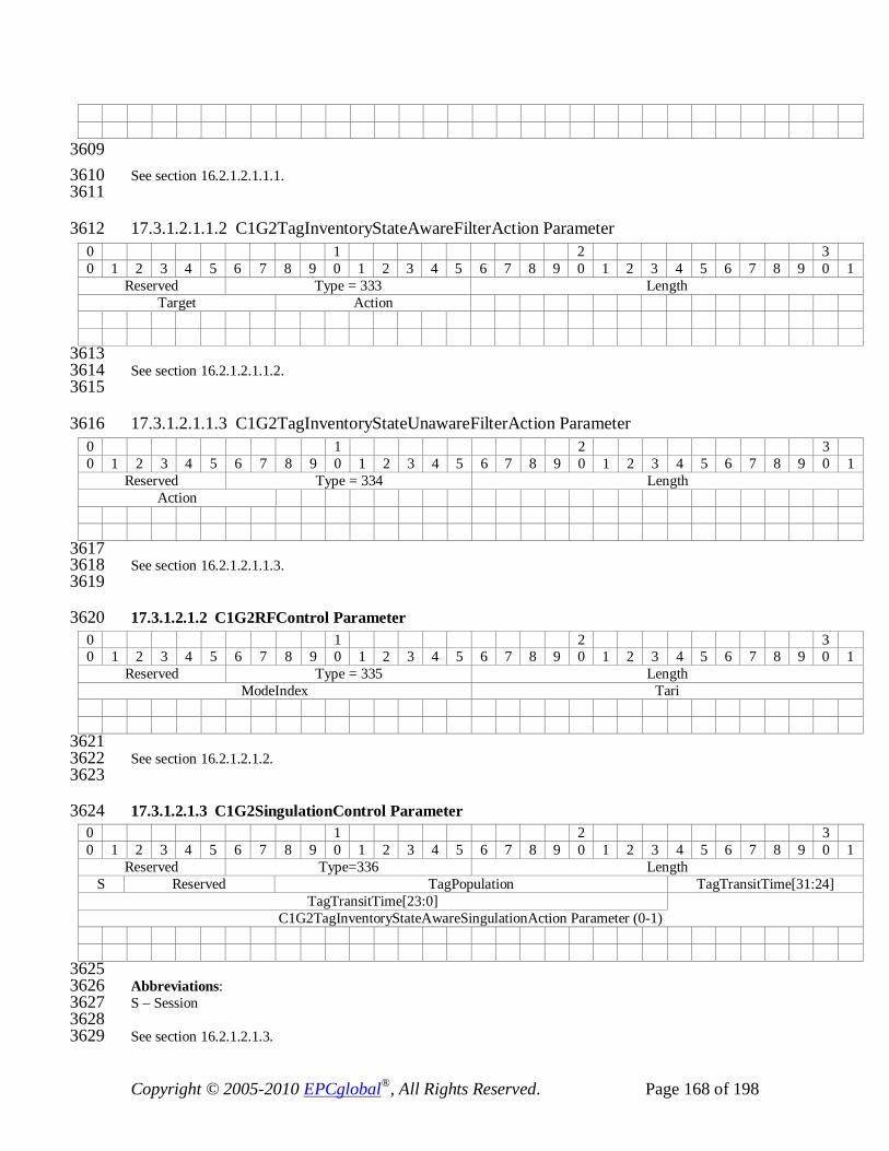
Copyright © 2005-2010 EPCglobal®, All Rights Reserved. Page 168 of 198
3609 See section 16.2.1.2.1.1.1. 3610 3611
17.3.1.2.1.1.2 C1G2TagInventoryStateAwareFilterAction Parameter 3612 0 1 2 3 0 1 2 3 4 5 6 7 8 9 0 1 2 3 4 5 6 7 8 9 0 1 2 3 4 5 6 7 8 9 0 1
Reserved Type = 333 Length Target Action
3613 See section 16.2.1.2.1.1.2. 3614 3615
17.3.1.2.1.1.3 C1G2TagInventoryStateUnawareFilterAction Parameter 3616 0 1 2 3 0 1 2 3 4 5 6 7 8 9 0 1 2 3 4 5 6 7 8 9 0 1 2 3 4 5 6 7 8 9 0 1
Reserved Type = 334 Length Action
3617 See section 16.2.1.2.1.1.3. 3618 3619
17.3.1.2.1.2 C1G2RFControl Parameter 3620 0 1 2 3 0 1 2 3 4 5 6 7 8 9 0 1 2 3 4 5 6 7 8 9 0 1 2 3 4 5 6 7 8 9 0 1
Reserved Type = 335 Length ModeIndex Tari
3621 See section 16.2.1.2.1.2. 3622 3623
17.3.1.2.1.3 C1G2SingulationControl Parameter 3624 0 1 2 3 0 1 2 3 4 5 6 7 8 9 0 1 2 3 4 5 6 7 8 9 0 1 2 3 4 5 6 7 8 9 0 1
Reserved Type=336 Length S Reserved TagPopulation TagTransitTime[31:24]
TagTransitTime[23:0] C1G2TagInventoryStateAwareSingulationAction Parameter (0-1)
3625 Abbreviations: 3626 S – Session 3627 3628 See section 16.2.1.2.1.3. 3629

Copyright © 2005-2010 EPCglobal®, All Rights Reserved. Page 169 of 198
3630
17.3.1.2.1.3.1 C1G2TagInventoryStateAwareSingulationAction Parameter 3631 0 1 2 3 0 1 2 3 4 5 6 7 8 9 0 1 2 3 4 5 6 7 8 9 0 1 2 3 4 5 6 7 8 9 0 1
Reserved Type = 337 Length I S A
3632 Abbreviations 3633
A – S_All 3634 3635 See section 16.2.1.2.1.3.1. 3636 3637
17.3.1.3 Access Operation Parameters 3638 This section of air protocol specific parameters corresponds to LLRP parameters 3639 encodings specified in section 16.2.1.3. 3640
17.3.1.3.1 C1G2TagSpec Parameter 3641 0 1 2 3 0 1 2 3 4 5 6 7 8 9 0 1 2 3 4 5 6 7 8 9 0 1 2 3 4 5 6 7 8 9 0 1
Reserved Type = 338 Length C1G2TargetTag Parameter
C1G2TargetTag Parameter (0-1)
3642 See section 16.2.1.3.1. 3643 3644
17.3.1.3.1.1 C1G2TargetTag Parameter 3645 3646
0 1 2 3 0 1 2 3 4 5 6 7 8 9 0 1 2 3 4 5 6 7 8 9 0 1 2 3 4 5 6 7 8 9 0 1
Reserved Type = 339 Length MB M Resvd Pointer MaskBitCount[15:8]
MaskBitCount[7:0]
Tag Mask
DataBitCount
Tag Data
3647 Abbreviations 3648
M – Match. 3649 3650 See section 16.2.1.3.1.1. 3651 3652
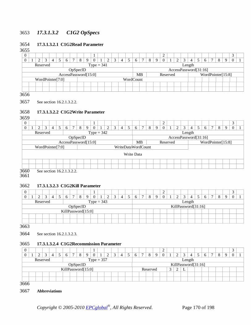
Copyright © 2005-2010 EPCglobal®, All Rights Reserved. Page 170 of 198
17.3.1.3.2 C1G2 OpSpecs 3653
17.3.1.3.2.1 C1G2Read Parameter 3654 3655
0 1 2 3 0 1 2 3 4 5 6 7 8 9 0 1 2 3 4 5 6 7 8 9 0 1 2 3 4 5 6 7 8 9 0 1
Reserved Type = 341 Length OpSpecID AccessPassword[31:16]
AccessPassword[15:0] MB Reserved WordPointer[15:8] WordPointer[7:0] WordCount
3656 See section 16.2.1.3.2.2. 3657
17.3.1.3.2.2 C1G2Write Parameter 3658 3659
0 1 2 3 0 1 2 3 4 5 6 7 8 9 0 1 2 3 4 5 6 7 8 9 0 1 2 3 4 5 6 7 8 9 0 1
Reserved Type = 342 Length OpSpecID AccessPassword[31:16]
AccessPassword[15:0] MB Reserved WordPointer[15:8] WordPointer[7:0] WriteDataWordCount
Write Data
See section 16.2.1.3.2.2. 3660 3661
17.3.1.3.2.3 C1G2Kill Parameter 3662 0 1 2 3 0 1 2 3 4 5 6 7 8 9 0 1 2 3 4 5 6 7 8 9 0 1 2 3 4 5 6 7 8 9 0 1
Reserved Type = 343 Length OpSpecID KillPassword[31:16]
KillPassword[15:0]
3663 See section 16.2.1.3.2.3. 3664
17.3.1.3.2.4 C1G2Recommission Parameter 3665 0 1 2 3 0 1 2 3 4 5 6 7 8 9 0 1 2 3 4 5 6 7 8 9 0 1 2 3 4 5 6 7 8 9 0 1
Reserved Type = 357 Length OpSpecID KillPassword[31:16]
KillPassword[15:0] Reserved 3 2 L
3666 Abbreviations 3667
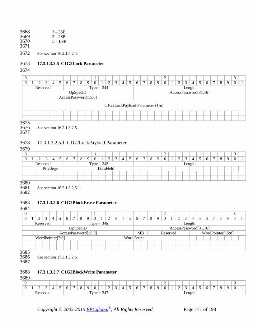
Copyright © 2005-2010 EPCglobal®, All Rights Reserved. Page 171 of 198
3 – 3SB 3668 2 – 2SB 3669 L – LSB 3670
3671 See section 16.2.1.3.2.4. 3672
17.3.1.3.2.5 C1G2Lock Parameter 3673 3674
0 1 2 3 0 1 2 3 4 5 6 7 8 9 0 1 2 3 4 5 6 7 8 9 0 1 2 3 4 5 6 7 8 9 0 1
Reserved Type = 344 Length OpSpecID AccessPassword[31:16]
AccessPassword[15:0]
C1G2LockPayload Parameter (1-n)
3675 See section 16.2.1.3.2.5. 3676 3677
17.3.1.3.2.5.1 C1G2LockPayload Parameter 3678 3679
0 1 2 3 0 1 2 3 4 5 6 7 8 9 0 1 2 3 4 5 6 7 8 9 0 1 2 3 4 5 6 7 8 9 0 1
Reserved Type = 345 Length Privilege DataField
3680 See section 16.2.1.3.2.5.1. 3681 3682
17.3.1.3.2.6 C1G2BlockErase Parameter 3683 3684
0 1 2 3 0 1 2 3 4 5 6 7 8 9 0 1 2 3 4 5 6 7 8 9 0 1 2 3 4 5 6 7 8 9 0 1
Reserved Type = 346 Length OpSpecID AccessPassword[31:16]
AccessPassword[15:0] MB Reserved WordPointer[15:8] WordPointer[7:0] WordCount
3685 See section 17.3.1.3.2.6. 3686 3687
17.3.1.3.2.7 C1G2BlockWrite Parameter 3688 3689
0 1 2 3 0 1 2 3 4 5 6 7 8 9 0 1 2 3 4 5 6 7 8 9 0 1 2 3 4 5 6 7 8 9 0 1
Reserved Type = 347 Length

Copyright © 2005-2010 EPCglobal®, All Rights Reserved. Page 172 of 198
OpSpecID AccessPassword[31:16] AccessPassword[15:0] MB Reserved WordPointer[15:8]
WordPointer[7:0] WriteDataWordCount
Write Data
3690 See section 16.2.1.3.2.7. 3691 3692
17.3.1.3.2.8 C1G2BlockPermalock Parameter 3693 0 1 2 3 0 1 2 3 4 5 6 7 8 9 0 1 2 3 4 5 6 7 8 9 0 1 2 3 4 5 6 7 8 9 0 1
Reserved Type = 358 Length OpSpecID AccessPassword[31:16]
AccessPassword[15:0] MB Reserved BlockPointer[15:8] BlockPointer[7:0] BlockMaskWordCount
BlockMask
3694 See section 16.2.1.3.2.8. 3695 3696
17.3.1.3.2.9 C1G2GetBlockPermalockStatus Parameter 3697 0 1 2 3 0 1 2 3 4 5 6 7 8 9 0 1 2 3 4 5 6 7 8 9 0 1 2 3 4 5 6 7 8 9 0 1
Reserved Type = 359 Length OpSpecID AccessPassword[31:16]
AccessPassword[15:0] MB Reserved BlockPointer[15:8] BlockPointer[7:0] BlockRange
3698 See section 16.2.1.5.7.9. 3699 3700
17.3.1.4 Configuration Parameters 3701 This section of air protocol specific parameters corresponds to LLRP parameters 3702 specified in Section 13.2. The only air protocol specific parameter is the 3703 AirProtocolInventoryCommandSettings parameter in the AntennaConfiguration (Section 3704 13.2.6). The C1G2 specific InventoryCommand is already defined in Section 17.3.1.2.1. 3705
3706
17.3.1.5 Reporting Parameters 3707 This section of air protocol specific parameters corresponds to LLRP parameters 3708 encodings specified in section 16.2.1.5. 3709

Copyright © 2005-2010 EPCglobal®, All Rights Reserved. Page 173 of 198
17.3.1.5.1 C1G2EPCMemorySelector Parameter 3710 3711
0 1 2 3 0 1 2 3 4 5 6 7 8 9 0 1 2 3 4 5 6 7 8 9 0 1 2 3 4 5 6 7 8 9 0 1
Reserved Type = 348 Length C P X Reserved
3712 Abbreviations 3713 3714
C – EnableCRC 3715 P – EnablePCBits 3716 X – EnableXPCBits 3717
3718 See section 16.2.1.5.1. 3719 3720
17.3.1.5.2 C1G2PC Parameter (TV-Encoding) 3721 0 1 2 3 0 1 2 3 4 5 6 7 8 9 0 1 2 3 4 5 6 7 8 9 0 1 2 3 4 5 6 7 8 9 0 1 1 Type=12 PC-Bits
3722 See section 16.2.1.5.2. 3723
17.3.1.5.3 C1G2XPCW1 Parameter (TV-Encoding) 3724 0 1 2 3 0 1 2 3 4 5 6 7 8 9 0 1 2 3 4 5 6 7 8 9 0 1 2 3 4 5 6 7 8 9 0 1 1 Type=19 XPC_W1
3725 See section 16.2.1.5.3. 3726
17.3.1.5.4 C1G2XPCW2 Parameter (TV-Encoding) 3727 0 1 2 3 0 1 2 3 4 5 6 7 8 9 0 1 2 3 4 5 6 7 8 9 0 1 2 3 4 5 6 7 8 9 0 1 1 Type=20 XPC_W2
3728 See section 16.2.1.5.4. 3729
17.3.1.5.5 C1G2CRC Parameter (TV-Encoding) 3730 0 1 2 3 0 1 2 3 4 5 6 7 8 9 0 1 2 3 4 5 6 7 8 9 0 1 2 3 4 5 6 7 8 9 0 1 1 Type=11 CRC
3731 See section 16.2.1.5.5. 3732
17.3.1.5.6 C1G2SingulationDetails Parameter (TV-Encoding) 3733 0 1 2 3 0 1 2 3 4 5 6 7 8 9 0 1 2 3 4 5 6 7 8 9 0 1 2 3 4 5 6 7 8 9 0 1 1 Type=18 NumCollisionSlots NumEmptySlots[15:8]
NumEmptySlots[7:0] 3734

Copyright © 2005-2010 EPCglobal®, All Rights Reserved. Page 174 of 198
See section 16.2.1.5.6. 3735
17.3.1.5.7 C1G2 OpSpec Results 3736
17.3.1.5.7.1 C1G2ReadOpSpecResult Parameter 3737 0 1 2 3 0 1 2 3 4 5 6 7 8 9 0 1 2 3 4 5 6 7 8 9 0 1 2 3 4 5 6 7 8 9 0 1
Reserved Type = 349 Length Result OpSpecID ReadDataWordCount[15:8]
ReadDataWordCount[7:0]
ReadData
3738 See section 16.2.1.5.7.1. 3739 3740
17.3.1.5.7.2 C1G2WriteOpSpecResult Parameter 3741 0 1 2 3 0 1 2 3 4 5 6 7 8 9 0 1 2 3 4 5 6 7 8 9 0 1 2 3 4 5 6 7 8 9 0 1
Reserved Type = 350 Length Result OpSpecID NumWordsWritten[15:8]
NumWordsWritten[7:0]
3742 See section 16.2.1.5.7.2. 3743 3744
17.3.1.5.7.3 C1G2KillOpSpecResult Parameter 3745 0 1 2 3 0 1 2 3 4 5 6 7 8 9 0 1 2 3 4 5 6 7 8 9 0 1 2 3 4 5 6 7 8 9 0 1
Reserved Type = 351 Length Result OpSpecID
3746 See section 16.2.1.5.7.3. 3747 3748
17.3.1.5.7.4 C1G2RecommissionOpSpecResult Parameter 3749 0 1 2 3 0 1 2 3 4 5 6 7 8 9 0 1 2 3 4 5 6 7 8 9 0 1 2 3 4 5 6 7 8 9 0 1
Reserved Type = 360 Length Result OpSpecID
3750 See section 16.2.1.5.7.4. 3751 3752
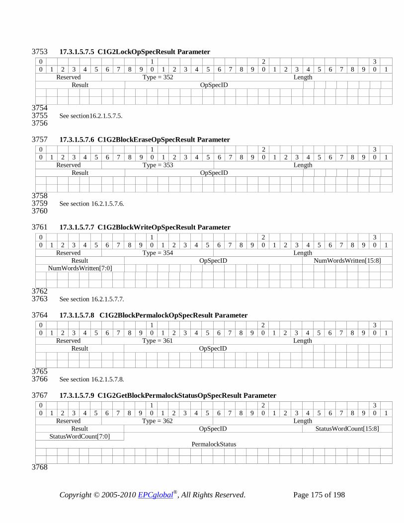
Copyright © 2005-2010 EPCglobal®, All Rights Reserved. Page 175 of 198
17.3.1.5.7.5 C1G2LockOpSpecResult Parameter 3753 0 1 2 3 0 1 2 3 4 5 6 7 8 9 0 1 2 3 4 5 6 7 8 9 0 1 2 3 4 5 6 7 8 9 0 1
Reserved Type = 352 Length Result OpSpecID
3754 See section16.2.1.5.7.5. 3755 3756
17.3.1.5.7.6 C1G2BlockEraseOpSpecResult Parameter 3757 0 1 2 3 0 1 2 3 4 5 6 7 8 9 0 1 2 3 4 5 6 7 8 9 0 1 2 3 4 5 6 7 8 9 0 1
Reserved Type = 353 Length Result OpSpecID
3758 See section 16.2.1.5.7.6. 3759 3760
17.3.1.5.7.7 C1G2BlockWriteOpSpecResult Parameter 3761 0 1 2 3 0 1 2 3 4 5 6 7 8 9 0 1 2 3 4 5 6 7 8 9 0 1 2 3 4 5 6 7 8 9 0 1
Reserved Type = 354 Length Result OpSpecID NumWordsWritten[15:8]
NumWordsWritten[7:0]
3762 See section 16.2.1.5.7.7. 3763
17.3.1.5.7.8 C1G2BlockPermalockOpSpecResult Parameter 3764 0 1 2 3 0 1 2 3 4 5 6 7 8 9 0 1 2 3 4 5 6 7 8 9 0 1 2 3 4 5 6 7 8 9 0 1
Reserved Type = 361 Length Result OpSpecID
3765 See section 16.2.1.5.7.8. 3766
17.3.1.5.7.9 C1G2GetBlockPermalockStatusOpSpecResult Parameter 3767 0 1 2 3 0 1 2 3 4 5 6 7 8 9 0 1 2 3 4 5 6 7 8 9 0 1 2 3 4 5 6 7 8 9 0 1
Reserved Type = 362 Length Result OpSpecID StatusWordCount[15:8]
StatusWordCount[7:0] PermalockStatus
3768
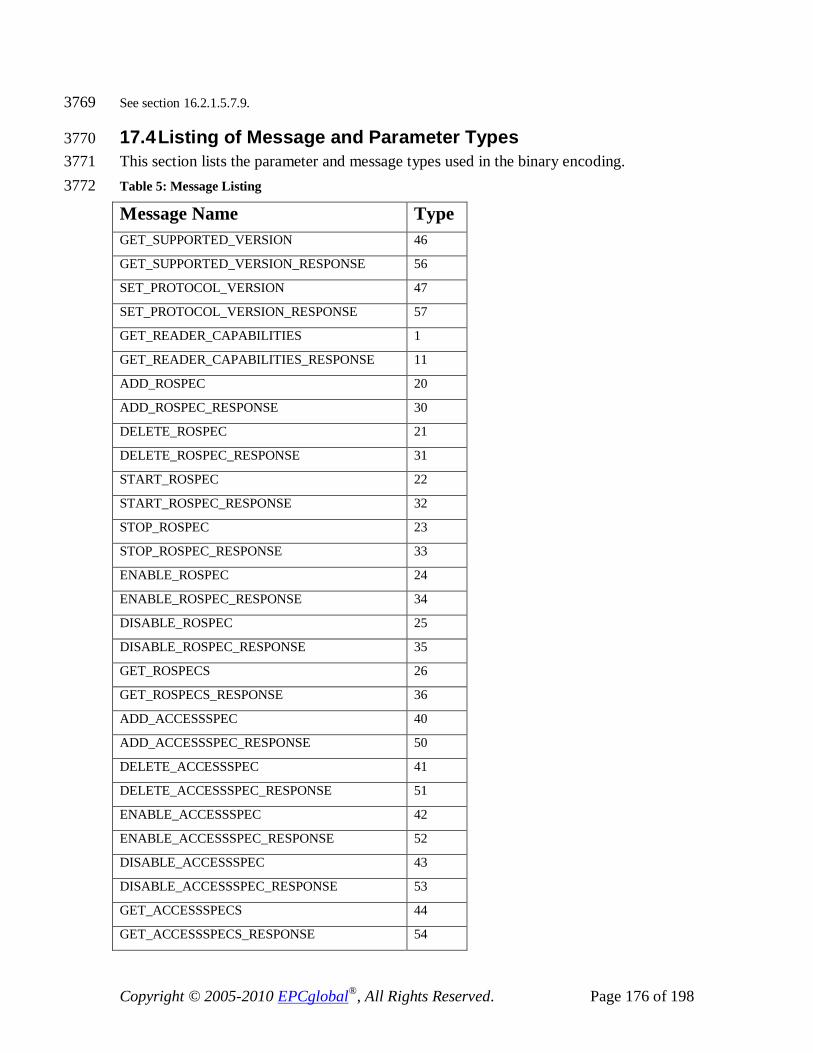
Copyright © 2005-2010 EPCglobal®, All Rights Reserved. Page 176 of 198
See section 16.2.1.5.7.9. 3769
17.4 Listing of Message and Parameter Types 3770 This section lists the parameter and message types used in the binary encoding. 3771 Table 5: Message Listing 3772
Message Name Type GET_SUPPORTED_VERSION 46
GET_SUPPORTED_VERSION_RESPONSE 56
SET_PROTOCOL_VERSION 47
SET_PROTOCOL_VERSION_RESPONSE 57
GET_READER_CAPABILITIES 1
GET_READER_CAPABILITIES_RESPONSE 11
ADD_ROSPEC 20
ADD_ROSPEC_RESPONSE 30
DELETE_ROSPEC 21
DELETE_ROSPEC_RESPONSE 31
START_ROSPEC 22
START_ROSPEC_RESPONSE 32
STOP_ROSPEC 23
STOP_ROSPEC_RESPONSE 33
ENABLE_ROSPEC 24
ENABLE_ROSPEC_RESPONSE 34
DISABLE_ROSPEC 25
DISABLE_ROSPEC_RESPONSE 35
GET_ROSPECS 26
GET_ROSPECS_RESPONSE 36
ADD_ACCESSSPEC 40
ADD_ACCESSSPEC_RESPONSE 50
DELETE_ACCESSSPEC 41
DELETE_ACCESSSPEC_RESPONSE 51
ENABLE_ACCESSSPEC 42
ENABLE_ACCESSSPEC_RESPONSE 52
DISABLE_ACCESSSPEC 43
DISABLE_ACCESSSPEC_RESPONSE 53
GET_ACCESSSPECS 44
GET_ACCESSSPECS_RESPONSE 54

Copyright © 2005-2010 EPCglobal®, All Rights Reserved. Page 177 of 198
CLIENT_REQUEST_OP 45
CLIENT_REQUEST_OP_RESPONSE 55
GET_REPORT 60
RO_ACCESS_REPORT 61
KEEPALIVE 62
KEEPALIVE_ACK 72
READER_EVENT_NOTIFICATION 63
ENABLE_EVENTS_AND_REPORTS 64
ERROR_MESSAGE 100
GET_READER_CONFIG 2
GET_READER_CONFIG_RESPONSE 12
SET_READER_CONFIG 3
SET_READER_CONFIG_RESPONSE 13
CLOSE_CONNECTION 14
CLOSE_CONNECTION_RESPONSE 4
CUSTOM_MESSAGE 1023
Reserved for ISO/IEC 24791-5 900-999
3773 Table 6: Parameter Listing 3774
Parameter Name Type TV-Encoded? UTCTimeStamp 128
Uptime 129
GeneralDeviceCapabilities 137
MaximumReceiveSensitivity 363
ReceiveSensitivityTableEntry 139
PerAntennaAirProtocol 140
GPIOCapabilities 141
LLRPCapabilities 142
RegulatoryCapabilities 143
UHFBandCapabilities 144
TransmitPowerLevelTableEntry 145
FrequencyInformation 146
FrequencyHopTable 147
FixedFrequencyTable 148
PerAntennaReceiveSensitivityRange 149
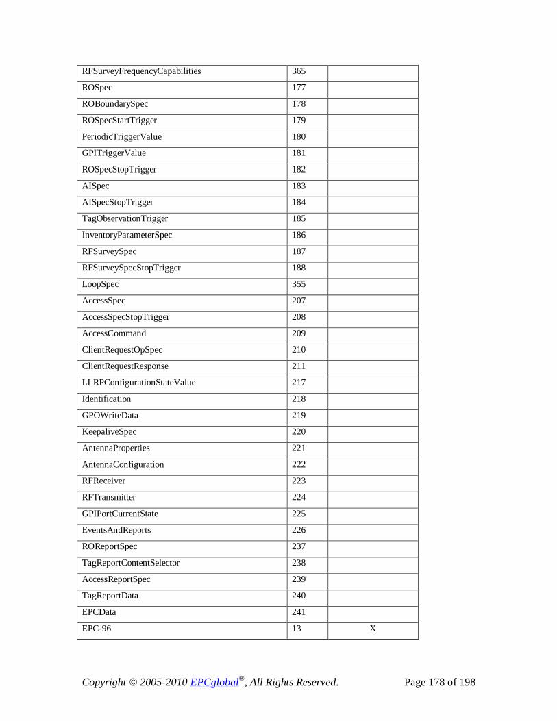
Copyright © 2005-2010 EPCglobal®, All Rights Reserved. Page 178 of 198
RFSurveyFrequencyCapabilities 365
ROSpec 177
ROBoundarySpec 178
ROSpecStartTrigger 179
PeriodicTriggerValue 180
GPITriggerValue 181
ROSpecStopTrigger 182
AISpec 183
AISpecStopTrigger 184
TagObservationTrigger 185
InventoryParameterSpec 186
RFSurveySpec 187
RFSurveySpecStopTrigger 188
LoopSpec 355
AccessSpec 207
AccessSpecStopTrigger 208
AccessCommand 209
ClientRequestOpSpec 210
ClientRequestResponse 211
LLRPConfigurationStateValue 217
Identification 218
GPOWriteData 219
KeepaliveSpec 220
AntennaProperties 221
AntennaConfiguration 222
RFReceiver 223
RFTransmitter 224
GPIPortCurrentState 225
EventsAndReports 226
ROReportSpec 237
TagReportContentSelector 238
AccessReportSpec 239
TagReportData 240
EPCData 241
EPC-96 13 X

Copyright © 2005-2010 EPCglobal®, All Rights Reserved. Page 179 of 198
ROSpecID 9 X
SpecIndex 14 X
InventoryParameterSpecID 10 X
AntennaID 1 X
PeakRSSI 6 X
ChannelIndex 7 X
FirstSeenTimestampUTC 2 X
FirstSeenTimestampUptime 3 X
LastSeenTimestampUTC 4 X
LastSeenTimestampUptime 5 X
TagSeenCount 8 X
ClientRequestOpSpecResult 15 X
AccessSpecID 16 X
RFSurveyReportData 242
FrequencyRSSILevelEntry 243
ReaderEventNotificationSpec 244
EventNotificationState 245
ReaderEventNotificationData 246
HoppingEvent 247
GPIEvent 248
ROSpecEvent 249
ReportBufferLevelWarningEvent 250
ReportBufferOverflowErrorEvent 251
ReaderExceptionEvent 252
OpSpecID 17 X
RFSurveyEvent 253
AISpecEvent 254
AntennaEvent 255
ConnectionAttemptEvent 256
ConnectionCloseEvent 257
SpecLoopEvent 356
LLRPStatus 287
FieldError 288
ParameterError 289
Custom 1023

Copyright © 2005-2010 EPCglobal®, All Rights Reserved. Page 180 of 198
C1G2LLRPCapabilities 327
UHFC1G2RFModeTable 328
UHFC1G2RFModeTableEntry 329
C1G2InventoryCommand 330
C1G2Filter 331
C1G2TagInventoryMask 332
C1G2TagInventoryStateAwareFilterAction 333
C1G2TagInventoryStateUnawareFilterAction 334
C1G2RFControl 335
C1G2SingulationControl 336
C1G2TagInventoryStateAwareSingulationAction 337
C1G2TagSpec 338
C1G2TargetTag 339
C1G2Read 341
C1G2Write 342
C1G2Kill 343
C1G2Recommission 357
C1G2Lock 344
C1G2LockPayload 345
C1G2BlockErase 346
C1G2BlockWrite 347
C1G2BlockPermalock 358
C1G2GetBlockPermalockStatus 359
C1G2EPCMemorySelector 348
C1G2PC 12 X
C1G2XPCW1 19 X
C1G2XPCW2 20 X
C1G2CRC 11 X
C1G2SingulationDetails 18 X
C1G2ReadOpSpecResult 349
C1G2WriteOpSpecResult 350
C1G2KillOpSpecResult 351
C1G2RecommissionOpSpecResult 360
C1G2LockOpSpecResult 352
C1G2BlockEraseOpSpecResult 353

Copyright © 2005-2010 EPCglobal®, All Rights Reserved. Page 181 of 198
C1G2BlockWriteOpSpecResult 354
C1G2BlockPermalockOpSpecResult 361
C1G2GetBlockPermalockStatusOpSpecResult 362
Reserved for ISO/IEC 24791-5 900-999
3775
18 Transmitter Behavior of a Reader 3776 A Reader SHALL enable its transmitter only under the following conditions: 3777
• When an ROSpec is in the active state. 3778 • Between a GET/SET_READER_CONFIG containing a RequestedData field with 3779
value 0 (All) or 2 (Antenna Properties) and the corresponding 3780 GET/SET_READER_CONFIG_RESPONSE. 3781
19 Future Versions of LLRP 3782 To ensure continued viability of the protocol, all backwards compatible versions of LLRP 3783 shall be implemented with the following restrictions. 3784
• In all future versions of LLRP, the following SHALL be prohibited: 3785 o New mandatory parameters in existing messages or parameters 3786 o New fields in existing messages or parameters 3787 o Changes to any existing field in messages or parameters 3788 o Changes to any messages involved in version negotiation 3789
• In all future versions of LLRP, new functionality SHALL be implemented by one 3790 of the following: 3791
o New optional parameters in existing messages or parameters 3792 o New extension points in existing messages or parameters. 3793 o Extending existing enumerated types 3794 o Using existing reserved bits 3795 o Adding new messages 3796 o Using custom extensions 3797

Copyright © 2005-2010 EPCglobal®, All Rights Reserved. Page 182 of 198
20 Connection and Transport 3798 The Reader SHALL maintain LLRP configuration state during an LLRP connection. 3799
The Reader MAY maintain configuration or data state when a connection fails, or across 3800 LLRP connections. 3801
20.1 TCP Transport 3802 LLRP end-to-end communications based on TCP/IP connections SHALL be 3803 implemented in accordance with the requirements specified in this section. These 3804 requirements are defined as the LLRP TCP Transport. 3805
20.1.1 Connection Establishment 3806 Readers SHALL be able to both initiate and accept LLRP TCP connections. Readers 3807 MAY be configured such that, at any given time, they only either initiate or accept an 3808 LLRP connection. If so, the mechanism for configuring a Reader to either initiate or 3809 accept an LLRP connection is not specified by LLRP. 3810 Clients SHALL be able both to initiate and accept LLRP TCP connections. Clients MAY 3811 be configured such that, at any given time, they only either initiate or accept an LLRP 3812 connection. If so, the mechanism for configuring a Client to either initiate or accept an 3813 LLRP connection is not specified by LLRP. 3814 For Readers and Clients, that are configured to accept connections, the default port is 3815 5084, as established by IANA (see http://www.iana.org/assignments/port-numbers), but 3816 other ports can be used. 3817
When a TCP connection (called the established connection) is initiated by either the 3818 Reader or the Client, the Reader SHALL reply with a status report message before 3819 communicating any other information. This report’s status parameter, 3820 ConnectionAttemptEvent, SHALL be set to indicate connection success (see section 3821 14.2.6.11). No other parameters may be contained within this message. The Client 3822 SHALL not send any information to the Reader until this status report message is 3823 received. 3824
20.1.2 Duplicate Connection Management 3825 Readers SHALL limit communications to a single established connection on a Reader IP 3826 address and TCP port. Readers MAY momentarily accept TCP connections (called 3827 momentary connections) in addition to the Reader’s one established connection on a 3828 Reader IP address and TCP port. If a momentary connection is accepted, then the Reader 3829 SHALL send a status report message on the Reader’s established connection. This 3830 report’s status parameter, ConnectionAttemptEvent, SHALL be set to indicate that 3831 another connection was attempted (see section 14.2.6.11). If this action results in a TCP 3832 error, then the Reader MAY close the established connection and then treat the 3833 momentary connection as a new established connection. In this case, the Reader SHALL 3834

Copyright © 2005-2010 EPCglobal®, All Rights Reserved. Page 183 of 198
reply with a status report message on the newly created established connection, as 3835 specified above, indicating connection success. 3836
If the established connection is not closed, then the Reader SHALL reply on the 3837 momentary connection with a status report message. This report’s status parameter, 3838 ConnectionAttemptEvent, SHALL be set to indicate connection failure. The Reader 3839 SHALL use the appropriate connection failed status value as defined in section 14.2.6.11. 3840 Once the connection failure message is sent, the Reader SHALL close the momentary 3841 connection. 3842
The following UML sequence diagrams illustrate different scenarios of a Reader and 3843 Client initiating TCP connections. 3844
3845 3846
3847 Figure 16: Reader Initiated Connection (Normal) 3848 3849
Reader Client
1. TCP Connect
Connect Accept
3. Client Message()
4. Reader Response()
Established connection.
Only one established connection allowed.
Reader Initiated Connection (normal case)
2. ReaderEventNotification = ConnectionAttemptEvent{Success}

Copyright © 2005-2010 EPCglobal®, All Rights Reserved. Page 184 of 198
3850 Figure 17: Reader Initiated Connection (Exception) 3851 3852 3853
3854 3855
3856 Figure 18: Client Initiated Connection (Normal) 3857 3858
Reader Client
1. TCP Connect
Connect Accept
3. Client Message()
4. Reader Response()
Established connection.
Only one established connection allowed.
Client Initiated Connection (normal case)
2. ReaderEventNotification = ConnectionAttemptEvent{Success}

Copyright © 2005-2010 EPCglobal®, All Rights Reserved. Page 185 of 198
3859 Figure 19: Client Initiated Connection (Exception #1) 3860
3861 Figure 20: Client Initiated Connection (exception #2) 3862 3863

Copyright © 2005-2010 EPCglobal®, All Rights Reserved. Page 186 of 198
3864 Figure 21: Client Initiated Connection (exception #3) 3865 3866
3867 3868
3869 Figure 22: Client Initiated Connection (exception #4) 3870 3871

Copyright © 2005-2010 EPCglobal®, All Rights Reserved. Page 187 of 198
3872 Figure 23: Client Initiated Connection (exception #5) 3873 3874
3875 Figure 24: Reader Initiated Close 3876 3877

Copyright © 2005-2010 EPCglobal®, All Rights Reserved. Page 188 of 198
3878 Figure 25: Client Initiated Close (Normal) 3879 3880
3881 Figure 26: Client Initiated Close (Exception) 3882

Copyright © 2005-2010 EPCglobal®, All Rights Reserved. Page 189 of 198
20.1.3 Version Negotiation 3883 LLRP version negotiation consists of the Client discovering the Reader’s supported 3884 protocol versions, selecting an appropriate, mutually supported version, and setting the 3885 version. Once selected, this version SHALL remain constant for the duration of the 3886 connection; renegotiation is not supported. For details regarding this process, see section 3887 9. 3888 Because version negotiation was introduced in LLRP 1.1, there exist scenarios where 3889 mismatched Client and Reader implementations must still successfully negotiate a 3890 protocol version. The following UML sequence diagrams illustrate different scenarios of 3891 a Reader and Client negotiating a protocol version. 3892 3893
Client(ver 1)
Reader(ver 1)
ReaderEventNotification=ConnectionAccepted()
Version 1 Messages
3894 Figure 27: Reader version 1, Client version 1 3895 3896
Client(ver 1)
Reader(ver 2+)
ReaderEventNotification=ConnectionAccepted()
Version 1 Messages
3897 Figure 28: Reader version 2+, Client version 1 3898 3899
Client(ver 2+)
Reader(ver 1)
ReaderEventNotification=ConnectionAccepted()
GET_SUPPORTED_VERSION
ERROR_MESSAGE=M_UnsupportedVersion()
SET_PROTOCOL_VERSION
ERROR_MESSAGE=M_UnsupportedVersion()
Version 1 Messages
3900
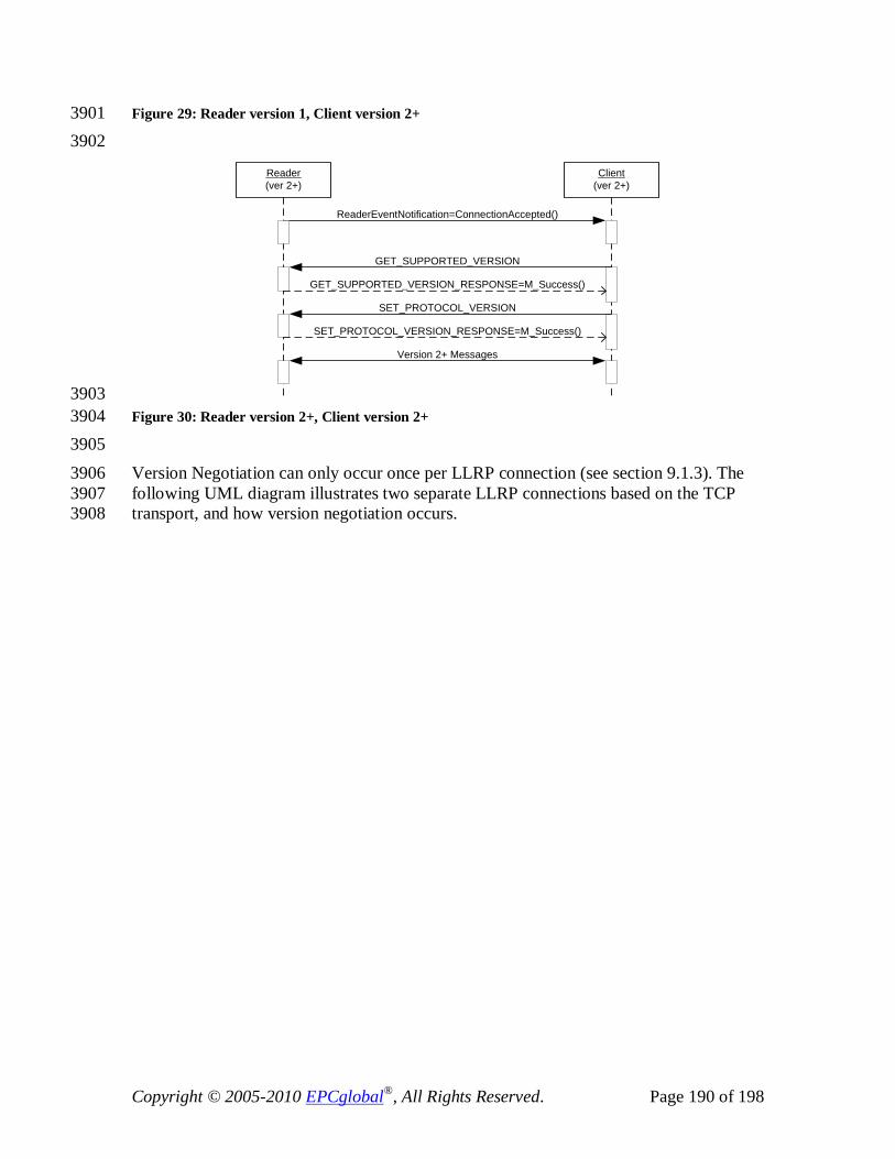
Copyright © 2005-2010 EPCglobal®, All Rights Reserved. Page 190 of 198
Figure 29: Reader version 1, Client version 2+ 3901 3902
Client(ver 2+)
Reader(ver 2+)
ReaderEventNotification=ConnectionAccepted()
GET_SUPPORTED_VERSION
GET_SUPPORTED_VERSION_RESPONSE=M_Success()
SET_PROTOCOL_VERSION
SET_PROTOCOL_VERSION_RESPONSE=M_Success()
Version 2+ Messages
3903 Figure 30: Reader version 2+, Client version 2+ 3904 3905 Version Negotiation can only occur once per LLRP connection (see section 9.1.3). The 3906 following UML diagram illustrates two separate LLRP connections based on the TCP 3907 transport, and how version negotiation occurs. 3908

Copyright © 2005-2010 EPCglobal®, All Rights Reserved. Page 191 of 198
Client(ver 2+)
Reader(ver 2+)
ReaderEventNotification=ConnectionAccepted()
GET_SUPPORTED_VERSION
GET_SUPPORTED_VERSION_RESPONSE=M_Success()
SET_PROTOCOL_VERSION
SET_PROTOCOL_VERSION_RESPONSE=M_Success()
TCPConnect()
Connect Accept
SET_PROTOCOL_VERSION
SET_PROTOCOL_VERSION_RESPONSE=M_UnexpectedMessage()
TCPClose()
ReaderEventNotification=ConnectionAccepted()
GET_SUPPORTED_VERSION
GET_SUPPORTED_VERSION_RESPONSE=M_Success()
SET_PROTOCOL_VERSION
SET_PROTOCOL_VERSION_RESPONSE=M_Success()
TCPConnect()
Connect Accept
LLR
P C
onne
ctio
n 1
LLR
P C
onne
ctio
n 2
3909 Figure 31: Version Negotiation across LLRP connections 3910
20.2 Security in TCP Transport 3911 This section describes the security aspects for LLRP connections running over a TCP 3912 transport binding. Refer to the previous section for any TCP connection related 3913 requirements. 3914
20.2.1 Normative Section 3915 The LLRP Client and LLRP Reader MAY implement TLS. The LLRP Client and LLRP 3916 Reader MAY use a different port for TLS LLRP connections and non-TLS LLRP 3917 connections. 3918 The LLRP Client MAY be capable of operating in a mixed deployment, where it 3919 communicates using TLS with a set of Readers and just plain TCP with a different set of 3920 Readers. In such mixed deployments, the LLRP Client MAY use different ports for TLS 3921 and non-TLS LLRP connections. The default port for TLS-LLRP connections is 5085, as 3922 established by IANA (see http://www.iana.org/assignments/port-numbers), but other 3923 ports can be used. 3924

Copyright © 2005-2010 EPCglobal®, All Rights Reserved. Page 192 of 198
The LLRP endpoint that initiates the TLS connection MAY be the same LLRP endpoint 3925 that initiated the underlying TCP connection. 3926
The LLRP endpoints SHALL use at least TLS1.0 [TLS10] and are recommended to use 3927 TLS1.1 [TLS11]. 3928
If the Reader or Client uses X.509 certificates[X509] for authentication, the certificates 3929 SHALL be compliant with the EPCGlobal Security2 working group specification 3930 [SEC2]. 3931
20.2.2 Informative Section 3932
20.2.2.1 Overview of TLS 3933 The TLS protocol provides privacy and data integrity between two authenticated 3934 communicating applications. TLS is a light weight transport protocol and has been 3935 proven to be reliable and secure by the use of millions of real users for many years. The 3936 strength of TLS can be chosen by the cipher suite negotiated by the two communicating 3937 parties through a flexible mechanism during the handshaking. 3938
TLS is particularly useful for TCP based applications. First, a TLS client initiates a 3939 connection with the TLS server. After a TLS connection is established, the applications 3940 can use the transport connection like an ordinary TCP connection, while having the added 3941 value that the data is protected and that both parties are mutually authenticated. 3942 For interoperability, a TLS client and server have to implement at least one common 3943 cipher suite. The credentials required for mutual authentication depend on the suite 3944 negotiated. For example, if the negotiated suite is using RSA for key exchange, then the 3945 server must own a server certificate (with private key) for RSA encryption purposes 3946 while the client must have a client certificate (with private key) for RSA signing 3947 purposes. Further, each side must have the root Certificate Authority (CA) certificates to 3948 verify the certificates presented by the peers. TLS also requires each party to present the 3949 CA certificates (except the root) that directly and indirectly issue the certificate. 3950
20.2.2.2 Threat Analysis for LLRP 3951 With TLS being used for Reader and Client communication, the following protections are 3952 provided, assuming that the credentials for the TLS client and server are not stolen: 3953
• Readers only talk to authorized LLRP Clients; 3954 • LLRP Clients only talk to authorized Readers; 3955 • No other party can read the LLRP messages (privacy protection) or inject/modify 3956
messages without being detected (integrity protection). 3957 Note that the strength of protection depends on the negotiated cipher suite. 3958
20.2.2.3 Configuration Elements for TLS 3959 In order to use TLS for LLRP, the following information has to be configured and/or 3960 provisioned at each entity (Reader or Client): 3961

Copyright © 2005-2010 EPCglobal®, All Rights Reserved. Page 193 of 198
• TLS enabled: Yes or no. If TLS is not enabled, the rest of the information need 3962 not be configured and the LLRP endpoint (Reader or Client) SHALL use TCP 3963 directly. 3964
• TLS role: Whether the LLRP endpoint is playing the TLS client or the TLS 3965 server role. A TLS client initiates a TCP connection to jump start TLS 3966 handshaking. A TLS server passively listens on the TCP server port. 3967
• Preferred list of cipher suites: A TLS client proposes the list of cipher suites to 3968 the TLS server during TLS handshaking. The TLS server will pick one suite from 3969 the proposed list if it is also in the preferred list maintained by the server. In TLS, 3970 the order of suites in the proposed list has no significance. Also, it is up to the 3971 server’s local policy to select when there are multiple choices. 3972
• Certificates and private keys: A TLS server needs a server certificate (with 3973 private key) for TLS server authentication. A TLS client needs a client certificate 3974 (with private key) for TLS client authentication. In each case, all the CA 3975 certificates (except the root) in the chain have to be available. 3976
• Root CA certificates: A TLS server needs to maintain the root CA certificate of 3977 the client certificate. This is used for verifying client certificates. A TLS client 3978 needs to maintain the root CA certificate of the server certificate. This is used for 3979 verifying server certificates. 3980
• List of authorized devices: Each TLS server MAY have a list of authorized TLS 3981 clients that can connect to it. Likewise, each TLS client MAY have a list of 3982 authorized TLS servers that it can connect to. 3983
3984 The configuration and/or provisioning of a LLRP endpoint is out of the scope of TLS and 3985 LLRP. Provisioning is important but does not affect the interoperability of LLRP. 3986 Vendors should have the flexibility to choose the most cost-effective ways (for 3987 provisioning and protecting provisioned credentials) based on designs, available 3988 technologies, potential threats, security requirements, and so on. This is a topic that 3989 should be addressed in DCI. 3990
20.2.2.4 Why different TLS server port? 3991 It is recommended that the TLS server should listen to a TCP port different from that for 3992 non-TLS mode for the following reasons: 3993
• If one of the endpoints has to be deployed behind firewalls, IT managers are 3994 more willing to open a port they know only TLS traffic can pass through. 3995
• Without using a different port, a non-TLS server may be confused by the TLS 3996 Client-Hello handshaking message. 3997
• Without using a different port, a TLS server may be confused by the LLRP 3998 application message (non-TLS handshaking message). 3999
• Without using a different port, for each new TCP connection, a server in a mixed 4000 environment (TLS and non-TLS) may have to wait a few moments to see if a 4001 Client-Hello message ever arrives from the client before it can conclude whether 4002 it is a TLS connection or not. 4003

Copyright © 2005-2010 EPCglobal®, All Rights Reserved. Page 194 of 198
• Without using a different port, it is potentially harder to implement a hybrid 4004 server if the server relies on third-party libraries for handling TLS. This is 4005 because the server application has to read the first message from the client to 4006 know if it is a TLS connection. It may be difficult for the TLS library to take over 4007 a connection after the TLS Client-Hello message has been consumed. 4008
4009
However, if a deployment in totality is only TLS or only non-TLS, the LLRP endpoint 4010 can be configured only as a TLS server or non-TLS server exclusively, then there should 4011 be no problem using the same port, as long as a non-TLS server can ignore TLS 4012 handshaking messages from a TLS client and as long as a TLS server can ignore non-4013 TLS handshaking messages from a non-TLS client. 4014

Copyright © 2005-2010 EPCglobal®, All Rights Reserved. Page 195 of 198
21 (Informative) TCP Keepalives 4015 The TCP specification doesn’t specify any specific handling of idle connections, where 4016 there is no data being transmitted by either end for a prolonged period of time. However, 4017 in some TCP implementations, there is an option called TCP-keepalive which may be 4018 turned on. If turned on, TCP-keepalive packets are sent only during periods of inactivity, 4019 on a configurable interval. If the connection is still valid, the other end responds with a 4020 segment containing an ack. If the connection is not valid the other end will reply with a 4021 connection reset (RST) and the connection is closed by this end. 4022
Due to events like network failures, or Client failures, half connections may remain at the 4023 Reader because the TCP connection was not cleanly terminated. If the Reader doesn’t 4024 implement TCP-keepalive, the only way to recover (i.e., reconnect to the Reader) may be 4025 to reboot the Reader. 4026
However, there are Readers for which intermittent connectivity may be a normal mode of 4027 operation – e.g., mobile Readers, handheld Readers. When connectivity is lost for these 4028 devices, the use of TCP-keepalive acts negatively and closes the TCP session 4029 prematurely before the TCP session would have timed out. If keepalives were not used, 4030 the mobile Reader would just start sending LLRP messages as soon as the link layer is re-4031 established without requiring a re-establishment of the TCP session as long as the TCP 4032 session did not timeout. 4033
22 (Informative) References 4034 [ISODir2] ISO, “Rules for the structure and drafting of International Standards (ISO/IEC 4035 Directives, Part 2, 2001, 4th edition),” July 2002. 4036 [C1G2] Class 1 Generation 2 UHF Air Interface Protocol Standard Version 1.0.9 4037
http://www.epcglobalinc.org/standards_technology/EPCglobal2UHFRFIDProtocolV10914038 22005.pdf
[ALE 1.0] EPCglobal Application Level Events (ALE) 1.0 Specification 4040
4039
http://www.epcglobalinc.org/standards_technology/EPCglobal_ApplicationALE_Specifi4041 cation_v112-2005.pdf[Class0]
4042 900 MHz Class 0 Radio Frequency (RF) Identification Tag Specification, 4043
http://www.epcglobalinc.org/standards_technology/Secure/v1.0/UHF-class0.pdf 4044 [Class1] 860MHz -- 930 MHz Class 1 Radio Frequency (RF) Identification Tag Radio 4045 Frequency & Logical Communication Interface Specification., 4046 http://www.epcglobalinc.org/standards_technology/Secure/v1.0/UHF-class1.pdf 4047
[ARC] EPCglobal Architecture Framework 1.0 4048 http://www.epcglobalinc.org/standards_technology/Final-epcglobal-arch-20050701.pdf 4049
[ISO3166] ISO, “Codes for the Representation of Names of Countries”. 4050 http://www.iso.org/iso/en/prods-services/iso3166ma/index.html 4051

Copyright © 2005-2010 EPCglobal®, All Rights Reserved. Page 196 of 198
[UTC] IETF RFC 3339, “Date and Time on the Internet: Timestamps”, July 2002. 4052 http://www.ietf.org/rfc/rfc3339.txt 4053
[EUI64] "Guidelines For 64-bit Global Identifier (EUI-64)", 4054 http://standards.ieee.org/db/oui/tutorials/EUI64.html 4055
[TLS11] IETF RFC 4346, “The Transport Layer Security (TLS) Protocol Version 1.1”. 4056 http://www.ietf.org/rfc/rfc4346.txt 4057
[TLS10] IETF RFC 2246, “The TLS Protocol Version 1.0”, 4058 http://www.ietf.org/rfc/rfc2246.txt 4059
[X509] ITU-T Recommendation X.509 (1997 E): Information Technology - Open 4060 Systems Interconnection - "The Directory Authentication Framework". 1988. 4061
[SEC2] EPCGlobal Certificate Profile, 4062 http://www.epcglobalinc.org/standards_technology/SAG%20Security%20Cert%20Profil4063 e%20March%208%202006.pdf[UTF8] IETF RFC 3629, “UTF-8, a transformation format of ISO 10646”, November 4065 2003. See also Annex D of ISO 10646-1:2000.
4064
http://www.ietf.org/rfc/rfc3629.txt 4066 [HK] OFTA 1049, 4067
http://www.ofta.gov.hk/en/standards/hktaspec/hkta1049.pdf#search=%22OFTA%2010494068 %22
[TW] DGT LP0002, 4070
4069
http://www.dgt.gov.tw/English/Type-approval/8.4/LP0002/LP0002-940324.pdf 4071
[JPN] ARIB STD T89, http://www.arib.or.jp/english/html/overview/st_j.html 4072 [KOR] MIC Article 5-2, (Radio Equipment for RFID/USN): Technical Requirements 4073 for the radio equipment for passive RFID using the frequency range of 908.5~914MHz. 4074 4075
4076
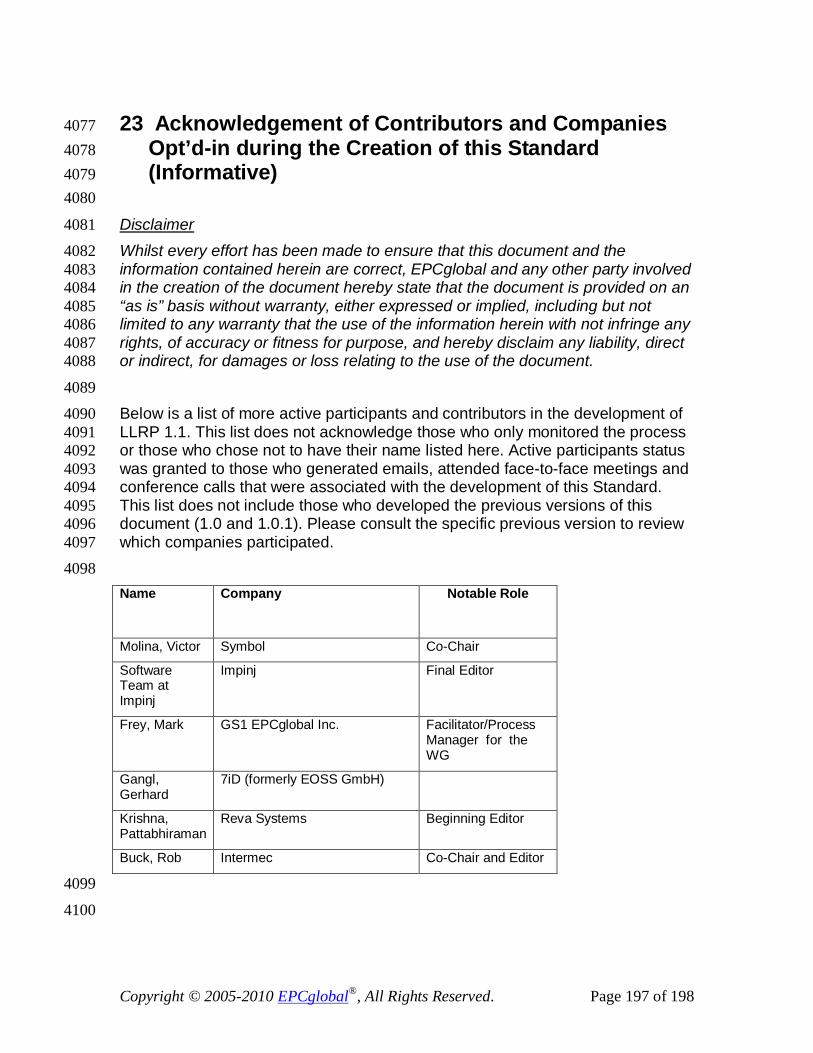
Copyright © 2005-2010 EPCglobal®, All Rights Reserved. Page 197 of 198
23 Acknowledgement of Contributors and Companies 4077 Opt’d-in during the Creation of this Standard 4078 (Informative) 4079
4080
Whilst every effort has been made to ensure that this document and the 4082 information contained herein are correct, EPCglobal and any other party involved 4083 in the creation of the document hereby state that the document is provided on an 4084 “as is” basis without warranty, either expressed or implied, including but not 4085 limited to any warranty that the use of the information herein with not infringe any 4086 rights, of accuracy or fitness for purpose, and hereby disclaim any liability, direct 4087 or indirect, for damages or loss relating to the use of the document. 4088
Disclaimer 4081
4089 Below is a list of more active participants and contributors in the development of 4090 LLRP 1.1. This list does not acknowledge those who only monitored the process 4091 or those who chose not to have their name listed here. Active participants status 4092 was granted to those who generated emails, attended face-to-face meetings and 4093 conference calls that were associated with the development of this Standard. 4094 This list does not include those who developed the previous versions of this 4095 document (1.0 and 1.0.1). Please consult the specific previous version to review 4096 which companies participated. 4097 4098 Name Company Notable Role
Molina, Victor Symbol Co-Chair
Software Team at Impinj
Impinj Final Editor
Frey, Mark GS1 EPCglobal Inc. Facilitator/Process Manager for the WG
Gangl, Gerhard
7iD (formerly EOSS GmbH)
Krishna, Pattabhiraman
Reva Systems Beginning Editor
Buck, Rob Intermec Co-Chair and Editor
4099
4100
Copyright © 2005-2010 EPCglobal®, All Rights Reserved. Page 198 of 198
The following list enumerates, in alphabetical order by company name, all companies 4101 that signed the EPCglobal IP Policy and the opt-in agreement for the EPCglobal Working 4102 Group that created the LLRP 1.1 standard. 4103
7iD (formerly EOSS GmbH) Afilias Limited Auto-ID Labs - ICU CAEN RFID SRL GS1 Australia GS1 China GS1 EPCglobal, Inc. GS1 Germany (CCG) GS1 Global Office GS1 Taiwan (EAN) IBM Corporation Impinj, Inc. Invengo Information Technology Co.,Ltd. LIT (Institute of Logistics Information Technology) Lyngsoe Systems MET Laboratories Psion Teklogix Inc. R R Indústria E Comércio De Etiquetas Ltda Supply Insight, Inc. Symbol Technologies Inc, a Motorola Co. TagSys Tibco Software, Inc
4104 4105


![[MS-RPCE]: Remote Procedure Call Protocol Extensions...Remote Procedure Call Protocol Extensions ... network programming art, and assumes that the reader either is familiar with the](https://img.dokumen.tips/doc/110x75/60e8c97abb09b25acd14b822/ms-rpce-remote-procedure-call-protocol-extensions-remote-procedure-call-protocol.jpg)