Embed Size (px)
Citation preview

Low Latency E-Tile 40G EthernetIntel® FPGA IP User Guide
Updated for Intel® Quartus® Prime Design Suite: 20.2
IP Version: 20.0.0
SubscribeSend Feedback
UG-20272 | 2020.06.22Latest document on the web: PDF | HTML
Contents
1. About the Low Latency E-Tile 40G Ethernet Intel FPGA IP.............................................. 41.1. Low Latency E-Tile 40G Ethernet IP Core Supported Features...................................... 41.2. Low Latency E-Tile 40G Ethernet Core Device Family and Speed Grade Support............. 6
1.2.1. Device Family Support................................................................................61.2.2. Low Latency E-Tile 40G Ethernet IP Core Device Speed Grade Support..............6
1.3. Resource Utilization............................................................................................... 61.4. Release Information...............................................................................................8
2. Low Latency E-Tile 40G Ethernet IP Core Parameters..................................................... 9
3. Getting Started............................................................................................................. 113.1. Installing and Licensing Intel FPGA IP Cores............................................................ 113.2. Specifying the Low Latency E-Tile 40G Ethernet IP Core Parameters and Options..........113.3. Simulating the IP Core..........................................................................................123.4. Generated File Structure.......................................................................................133.5. Integrating Your IP Core in Your Design.................................................................. 16
3.5.1. Pin Assignments...................................................................................... 163.5.2. Ethernet Adaptation Flow.......................................................................... 163.5.3. Placement Settings for the Low Latency E-Tile 40G Ethernet Core...................17
3.6. Low Latency E-Tile 40G Ethernet IP Core Testbench.................................................173.6.1. Understanding the Testbench Behavior........................................................17
3.7. Compiling the Full Design and Programming the FPGA.............................................. 18
4. Functional Description.................................................................................................. 194.1. Low Latency E-Tile 40G Ethernet Core Functional Description.....................................19
4.1.1. Low Latency E-Tile 40G Ethernet Core TX MAC Datapath............................... 204.1.2. Low Latency E-Tile 40G Ethernet Core RX MAC Datapath............................... 214.1.3. Link Fault Signaling Interface.....................................................................244.1.4. Flow Control............................................................................................25
4.2. User Interface to Ethernet Transmission..................................................................284.2.1. Order of Transmission...............................................................................284.2.2. Bit Order For TX and RX Datapaths.............................................................29
5. Reset............................................................................................................................ 30
6. Interfaces and Signal Descriptions............................................................................... 326.1. TX MAC Interface to User Logic..............................................................................326.2. RX MAC Interface to User Logic..............................................................................346.3. Transceivers........................................................................................................356.4. Transceiver Reconfiguration Signals........................................................................366.5. Avalon Memory-Mapped Management Interface....................................................... 376.6. Miscellaneous Status and Debug Signals................................................................. 376.7. Reset Signals...................................................................................................... 386.8. Clocks................................................................................................................ 386.9. Flow Control Interface.......................................................................................... 39
7. Control, Status, and Statistics Register Descriptions.....................................................417.1. PHY Registers......................................................................................................417.2. TX MAC Registers.................................................................................................44
Contents
Low Latency E-Tile 40G Ethernet Intel® FPGA IP User Guide Send Feedback
2
7.3. RX MAC Registers................................................................................................ 457.4. Pause/PFC Flow Control Registers...........................................................................45
8. Debugging the Link.......................................................................................................50
9. Low Latency E-Tile 40G Ethernet Intel FPGA IP User Guide Archives............................ 52
10. Comparison Between Low Latency E-Tile 40G Ethernet Core and Low Latency40GbE IP Core......................................................................................................... 53
11. Document Revision History......................................................................................... 55
Contents
Send Feedback Low Latency E-Tile 40G Ethernet Intel® FPGA IP User Guide
3

1. About the Low Latency E-Tile 40G Ethernet Intel FPGAIP
The Low Latency E-Tile 40-Gbps Ethernet (LL E-Tile 40GbE) IP core is used in multiplevariants of the Intel® Stratix® 10 and Intel Agilex™device families. The IP coreimplements the IEEE 802.3-2010 40G Ethernet Standard and includes options tosupport unidirectional transport as defined in Clause 66 of the IEEE 802.3-2012Ethernet Standard.
The MAC client side interface for the Low Latency E-Tile 40G Ethernet IP core is a 128-bit Avalon® streaming interface and a 32-bit Avalon memory-mapped interface controlpath. The network interfaces are standard XLAUI interfaces.
The IP core provides standard media access control (MAC), physical coding sublayer(PCS), and physical medium attachment (PMA) functions.
Figure 1. Low Latency E-Tile 40G Ethernet Block DiagramMain blocks, internal connections, and external block requirements.
Low Latency E-Tile 40G Ethernet FPGA IP Core
TXFIFO PMA
PMARXPCS
TXPCS
Avalon
Avalon
Control andStatus Interface
Transceiver
ReconfigurationInterface
Avalon memory-
CLK_REF
LL 40-GbE MAC
To optical module, backplane,or separate device
From optical module, backplane,or separate device
Fromclient application logic
Toclient application logic
TX MAC
RX MAC
streaming interface
streaming interface
mapped interface
Avalon memory-mapped interface
1.1. Low Latency E-Tile 40G Ethernet IP Core Supported Features
The Low Latency E-Tile 40G Ethernet IP core supports the following features:
• Parameterizable through the IP Catalog available with the Intel Quartus® Primesoftware.
• Designed to the IEEE 802.3ba-2010 High Speed Ethernet Standard available onthe IEEE website (www.ieee.org).
• Soft PCS logic that interfaces seamlessly to Intel FPGA 10.3125 gigabits persecond (Gbps) serial transceivers.
UG-20272 | 2020.06.22
Send Feedback
Intel Corporation. All rights reserved. Agilex, Altera, Arria, Cyclone, Enpirion, Intel, the Intel logo, MAX, Nios,Quartus and Stratix words and logos are trademarks of Intel Corporation or its subsidiaries in the U.S. and/orother countries. Intel warrants performance of its FPGA and semiconductor products to current specifications inaccordance with Intel's standard warranty, but reserves the right to make changes to any products and servicesat any time without notice. Intel assumes no responsibility or liability arising out of the application or use of anyinformation, product, or service described herein except as expressly agreed to in writing by Intel. Intelcustomers are advised to obtain the latest version of device specifications before relying on any publishedinformation and before placing orders for products or services.*Other names and brands may be claimed as the property of others.
ISO9001:2015Registered
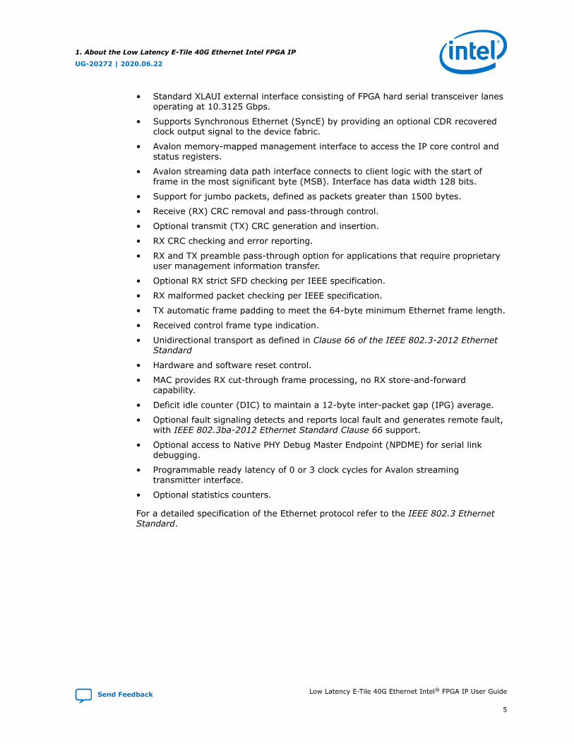
• Standard XLAUI external interface consisting of FPGA hard serial transceiver lanesoperating at 10.3125 Gbps.
• Supports Synchronous Ethernet (SyncE) by providing an optional CDR recoveredclock output signal to the device fabric.
• Avalon memory-mapped management interface to access the IP core control andstatus registers.
• Avalon streaming data path interface connects to client logic with the start offrame in the most significant byte (MSB). Interface has data width 128 bits.
• Support for jumbo packets, defined as packets greater than 1500 bytes.
• Receive (RX) CRC removal and pass-through control.
• Optional transmit (TX) CRC generation and insertion.
• RX CRC checking and error reporting.
• RX and TX preamble pass-through option for applications that require proprietaryuser management information transfer.
• Optional RX strict SFD checking per IEEE specification.
• RX malformed packet checking per IEEE specification.
• TX automatic frame padding to meet the 64-byte minimum Ethernet frame length.
• Received control frame type indication.
• Unidirectional transport as defined in Clause 66 of the IEEE 802.3-2012 EthernetStandard
• Hardware and software reset control.
• MAC provides RX cut-through frame processing, no RX store-and-forwardcapability.
• Deficit idle counter (DIC) to maintain a 12-byte inter-packet gap (IPG) average.
• Optional fault signaling detects and reports local fault and generates remote fault,with IEEE 802.3ba-2012 Ethernet Standard Clause 66 support.
• Optional access to Native PHY Debug Master Endpoint (NPDME) for serial linkdebugging.
• Programmable ready latency of 0 or 3 clock cycles for Avalon streamingtransmitter interface.
• Optional statistics counters.
For a detailed specification of the Ethernet protocol refer to the IEEE 802.3 EthernetStandard.
1. About the Low Latency E-Tile 40G Ethernet Intel FPGA IP
UG-20272 | 2020.06.22
Send Feedback Low Latency E-Tile 40G Ethernet Intel® FPGA IP User Guide
5
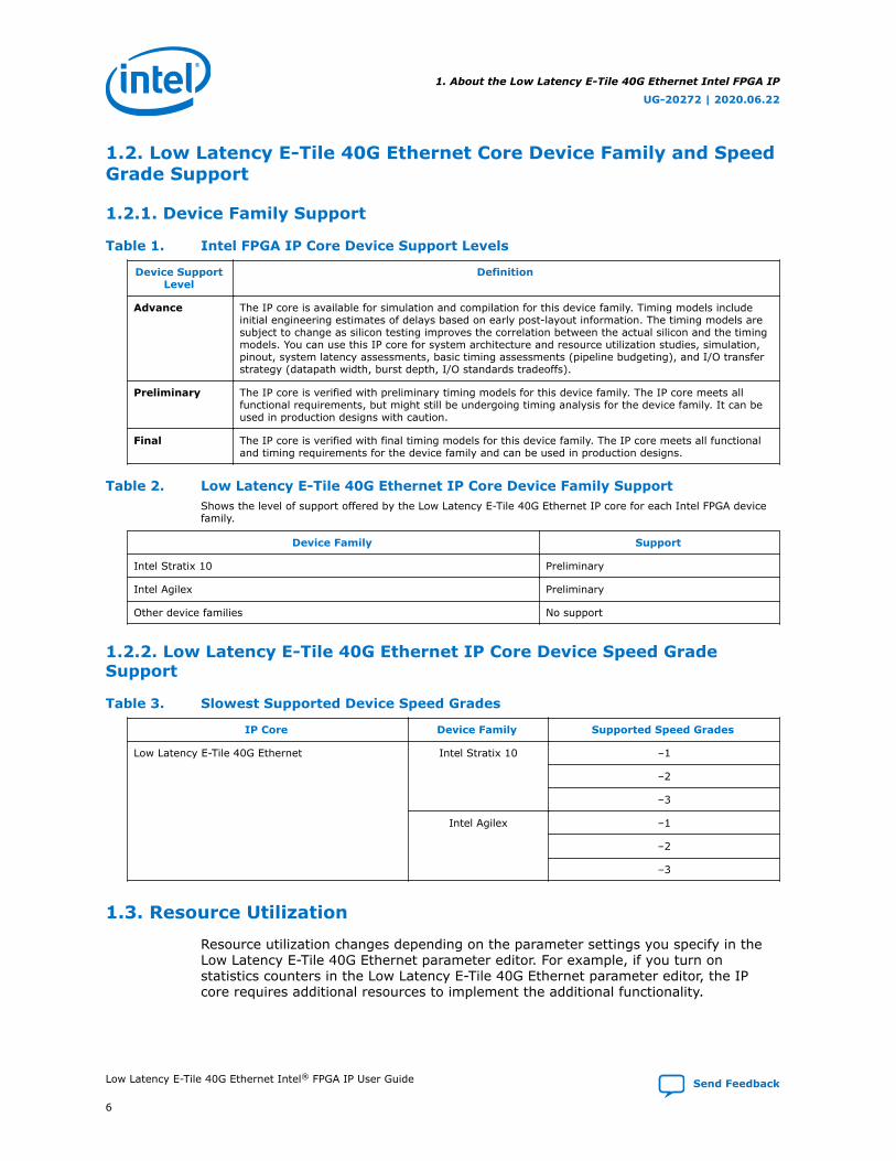
1.2. Low Latency E-Tile 40G Ethernet Core Device Family and SpeedGrade Support
1.2.1. Device Family Support
Table 1. Intel FPGA IP Core Device Support Levels
Device SupportLevel
Definition
Advance The IP core is available for simulation and compilation for this device family. Timing models includeinitial engineering estimates of delays based on early post-layout information. The timing models aresubject to change as silicon testing improves the correlation between the actual silicon and the timingmodels. You can use this IP core for system architecture and resource utilization studies, simulation,pinout, system latency assessments, basic timing assessments (pipeline budgeting), and I/O transferstrategy (datapath width, burst depth, I/O standards tradeoffs).
Preliminary The IP core is verified with preliminary timing models for this device family. The IP core meets allfunctional requirements, but might still be undergoing timing analysis for the device family. It can beused in production designs with caution.
Final The IP core is verified with final timing models for this device family. The IP core meets all functionaland timing requirements for the device family and can be used in production designs.
Table 2. Low Latency E-Tile 40G Ethernet IP Core Device Family SupportShows the level of support offered by the Low Latency E-Tile 40G Ethernet IP core for each Intel FPGA devicefamily.
Device Family Support
Intel Stratix 10 Preliminary
Intel Agilex Preliminary
Other device families No support
1.2.2. Low Latency E-Tile 40G Ethernet IP Core Device Speed GradeSupport
Table 3. Slowest Supported Device Speed Grades
IP Core Device Family Supported Speed Grades
Low Latency E-Tile 40G Ethernet Intel Stratix 10 –1
–2
–3
Intel Agilex –1
–2
–3
1.3. Resource Utilization
Resource utilization changes depending on the parameter settings you specify in theLow Latency E-Tile 40G Ethernet parameter editor. For example, if you turn onstatistics counters in the Low Latency E-Tile 40G Ethernet parameter editor, the IPcore requires additional resources to implement the additional functionality.
1. About the Low Latency E-Tile 40G Ethernet Intel FPGA IP
UG-20272 | 2020.06.22
Low Latency E-Tile 40G Ethernet Intel® FPGA IP User Guide Send Feedback
6
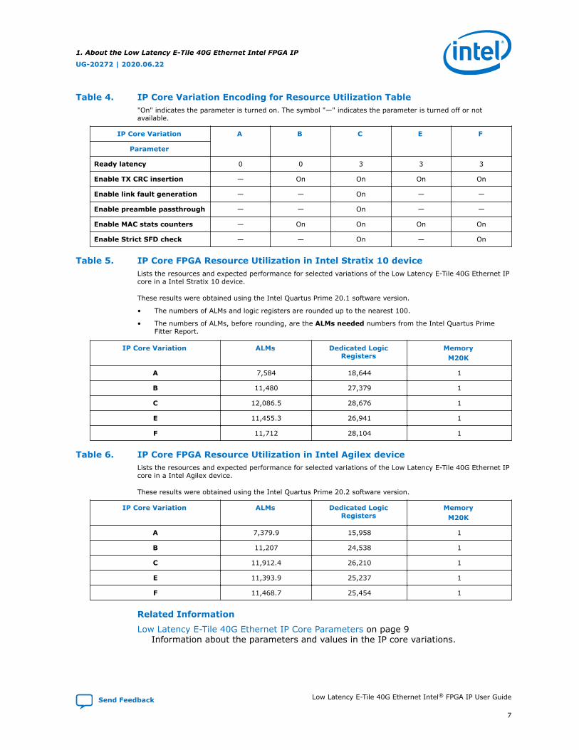
Table 4. IP Core Variation Encoding for Resource Utilization Table"On" indicates the parameter is turned on. The symbol "—" indicates the parameter is turned off or notavailable.
IP Core Variation A B C E F
Parameter
Ready latency 0 0 3 3 3
Enable TX CRC insertion — On On On On
Enable link fault generation — — On — —
Enable preamble passthrough — — On — —
Enable MAC stats counters — On On On On
Enable Strict SFD check — — On — On
Table 5. IP Core FPGA Resource Utilization in Intel Stratix 10 deviceLists the resources and expected performance for selected variations of the Low Latency E-Tile 40G Ethernet IPcore in a Intel Stratix 10 device.
These results were obtained using the Intel Quartus Prime 20.1 software version.
• The numbers of ALMs and logic registers are rounded up to the nearest 100.
• The numbers of ALMs, before rounding, are the ALMs needed numbers from the Intel Quartus PrimeFitter Report.
IP Core Variation ALMs Dedicated LogicRegisters
MemoryM20K
A 7,584 18,644 1
B 11,480 27,379 1
C 12,086.5 28,676 1
E 11,455.3 26,941 1
F 11,712 28,104 1
Table 6. IP Core FPGA Resource Utilization in Intel Agilex deviceLists the resources and expected performance for selected variations of the Low Latency E-Tile 40G Ethernet IPcore in a Intel Agilex device.
These results were obtained using the Intel Quartus Prime 20.2 software version.
IP Core Variation ALMs Dedicated LogicRegisters
MemoryM20K
A 7,379.9 15,958 1
B 11,207 24,538 1
C 11,912.4 26,210 1
E 11,393.9 25,237 1
F 11,468.7 25,454 1
Related Information
Low Latency E-Tile 40G Ethernet IP Core Parameters on page 9Information about the parameters and values in the IP core variations.
1. About the Low Latency E-Tile 40G Ethernet Intel FPGA IP
UG-20272 | 2020.06.22
Send Feedback Low Latency E-Tile 40G Ethernet Intel® FPGA IP User Guide
7
1.4. Release Information
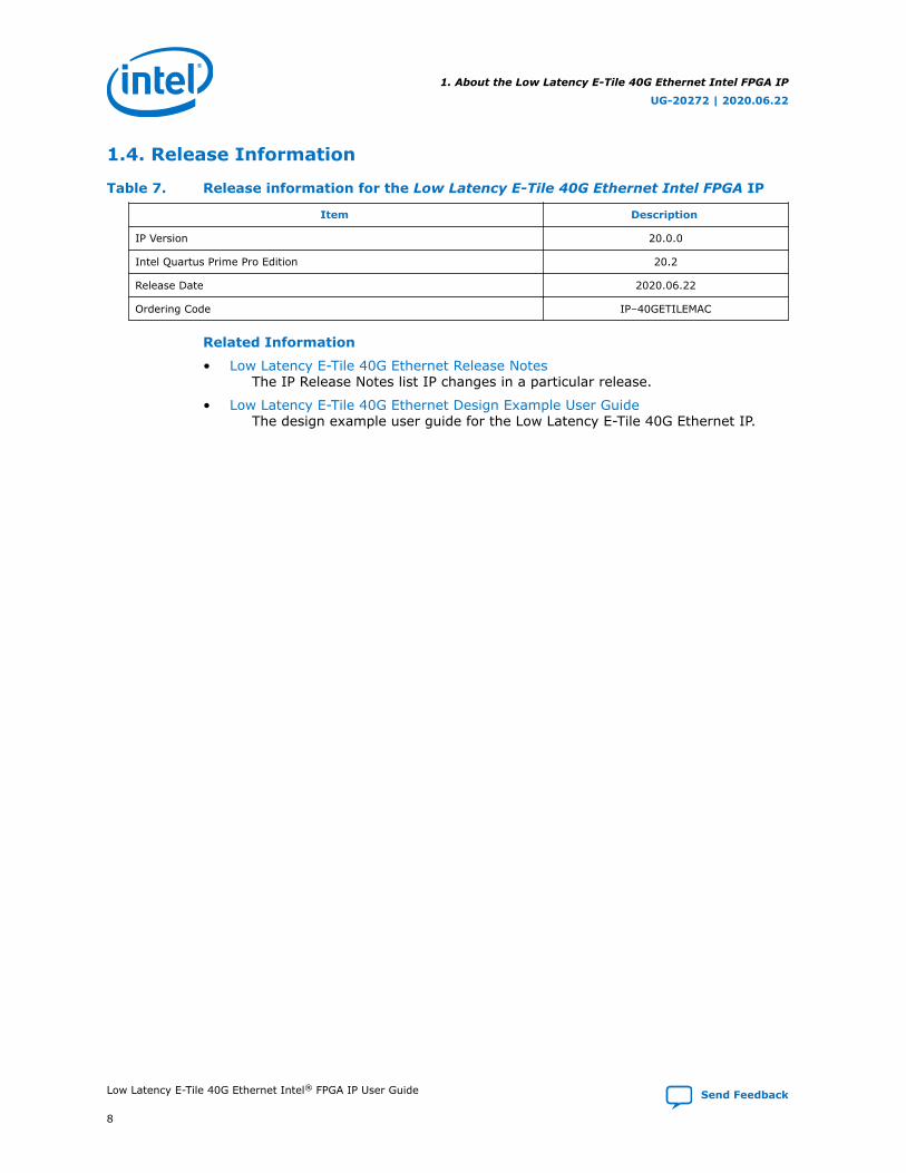
Table 7. Release information for the Low Latency E-Tile 40G Ethernet Intel FPGA IP
Item Description
IP Version 20.0.0
Intel Quartus Prime Pro Edition 20.2
Release Date 2020.06.22
Ordering Code IP–40GETILEMAC
Related Information
• Low Latency E-Tile 40G Ethernet Release NotesThe IP Release Notes list IP changes in a particular release.
• Low Latency E-Tile 40G Ethernet Design Example User GuideThe design example user guide for the Low Latency E-Tile 40G Ethernet IP.
1. About the Low Latency E-Tile 40G Ethernet Intel FPGA IP
UG-20272 | 2020.06.22
Low Latency E-Tile 40G Ethernet Intel® FPGA IP User Guide Send Feedback
8
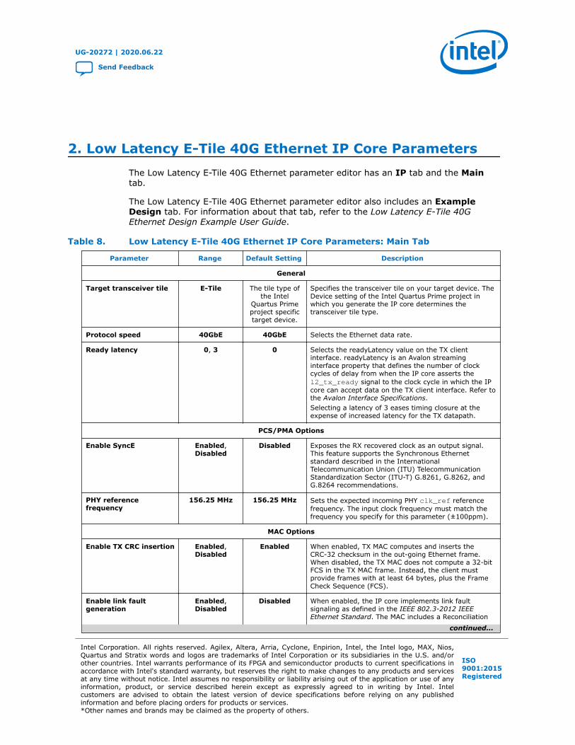
2. Low Latency E-Tile 40G Ethernet IP Core ParametersThe Low Latency E-Tile 40G Ethernet parameter editor has an IP tab and the Maintab.
The Low Latency E-Tile 40G Ethernet parameter editor also includes an ExampleDesign tab. For information about that tab, refer to the Low Latency E-Tile 40GEthernet Design Example User Guide.
Table 8. Low Latency E-Tile 40G Ethernet IP Core Parameters: Main Tab
Parameter Range Default Setting Description
General
Target transceiver tile E-Tile The tile type ofthe Intel
Quartus Primeproject specifictarget device.
Specifies the transceiver tile on your target device. TheDevice setting of the Intel Quartus Prime project inwhich you generate the IP core determines thetransceiver tile type.
Protocol speed 40GbE 40GbE Selects the Ethernet data rate.
Ready latency 0, 3 0 Selects the readyLatency value on the TX clientinterface. readyLatency is an Avalon streaminginterface property that defines the number of clockcycles of delay from when the IP core asserts thel2_tx_ready signal to the clock cycle in which the IPcore can accept data on the TX client interface. Refer tothe Avalon Interface Specifications.Selecting a latency of 3 eases timing closure at theexpense of increased latency for the TX datapath.
PCS/PMA Options
Enable SyncE Enabled,Disabled
Disabled Exposes the RX recovered clock as an output signal.This feature supports the Synchronous Ethernetstandard described in the InternationalTelecommunication Union (ITU) TelecommunicationStandardization Sector (ITU-T) G.8261, G.8262, andG.8264 recommendations.
PHY referencefrequency
156.25 MHz 156.25 MHz Sets the expected incoming PHY clk_ref referencefrequency. The input clock frequency must match thefrequency you specify for this parameter (±100ppm).
MAC Options
Enable TX CRC insertion Enabled,Disabled
Enabled When enabled, TX MAC computes and inserts theCRC-32 checksum in the out-going Ethernet frame.When disabled, the TX MAC does not compute a 32-bitFCS in the TX MAC frame. Instead, the client mustprovide frames with at least 64 bytes, plus the FrameCheck Sequence (FCS).
Enable link faultgeneration
Enabled,Disabled
Disabled When enabled, the IP core implements link faultsignaling as defined in the IEEE 802.3-2012 IEEEEthernet Standard. The MAC includes a Reconciliation
continued...
UG-20272 | 2020.06.22
Send Feedback
Intel Corporation. All rights reserved. Agilex, Altera, Arria, Cyclone, Enpirion, Intel, the Intel logo, MAX, Nios,Quartus and Stratix words and logos are trademarks of Intel Corporation or its subsidiaries in the U.S. and/orother countries. Intel warrants performance of its FPGA and semiconductor products to current specifications inaccordance with Intel's standard warranty, but reserves the right to make changes to any products and servicesat any time without notice. Intel assumes no responsibility or liability arising out of the application or use of anyinformation, product, or service described herein except as expressly agreed to in writing by Intel. Intelcustomers are advised to obtain the latest version of device specifications before relying on any publishedinformation and before placing orders for products or services.*Other names and brands may be claimed as the property of others.
ISO9001:2015Registered

Parameter Range Default Setting Description
Sublayer (RS) to manage local and remote faults. Whenenabled, the local RS TX logic can transmit remote faultsequences in case of a local fault and can transmit IDLEcontrol words in case of a remote fault.
Enable preamblepassthrough
Enabled,Disabled
Disabled When enabled, the IP core is in RX and TX preamblepass-through mode. In RX preamble pass-throughmode, the IP core passes the preamble and StartFrame Delimiter (SFD) to the client instead of strippingthem out of the Ethernet packet. In TX preamble pass-through mode, the client specifies the preamble andprovides the SFD to be sent in the Ethernet frame.
Enable MAC statscounters
Enabled,Disabled
Enabled When enabled, the IP core includes statistics countersthat characterize TX and RX traffic. The statisticsmodule also supports shadow requests that verifycounts by taking snapshots of intermediate results.
Enable Strict SFD check Enabled,Disabled
Disabled When enabled, the IP core can implement strict SFDchecking, depending on register settings.
Flow Control Options
Enable MAC flowcontrol
Enabled,Disabled
Disabled When enabled, the IP core implements flow control.When either link partner experiences congestion, therespective transmit control sends pause frames.
Number of queues inpriority flow control
1-8 8 Specifies the number of queues used in managing flowcontrol.
Configuration, Debug and Extension Options
Enable Native PHYDebug Master Endpoint(NPDME)
Enabled,Disabled
Disabled If this parameter is turned on, the E-Tile TransceiverNative PHY IP includes an embedded Native PHY DebugMaster Endpoint that connects internally to the Avalonmemory-mapped slave interface for dynamicreconfiguration. The Native PHY Debug Master Endpointcan access the transceiver's reconfiguration space. Itcan perform certain tests and debug functions via JTAGusing the System Console.
Enable JTAG to AvalonMaster Bridge
Enabled,Disabled
Disabled If turned on, the IP core includes a JTAG to Avalonmemory-mapped interface master bridge connectinginternally to status and reconfiguration registers.
Related Information
• Low Latency E-Tile 40G Ethernet Design Example User GuideInformation about the parameters on the Example Design tab.
• Avalon Interface SpecificationsDetailed information about Avalon streaming interfaces and the Avalonstreaming interface readyLatency parameter.
• E-Tile Transceiver PHY User GuideInformation about the NPDME and Enable capability registers parametersof the E-Tile Transceiver PHY IP core.
2. Low Latency E-Tile 40G Ethernet IP Core Parameters
UG-20272 | 2020.06.22
Low Latency E-Tile 40G Ethernet Intel® FPGA IP User Guide Send Feedback
10

3. Getting Started
3.1. Installing and Licensing Intel FPGA IP Cores
The Intel Quartus Prime software installation includes the Intel FPGA IP library. Thislibrary provides many useful IP cores for your production use without the need for anadditional license. Some Intel FPGA IP cores require purchase of a separate license forproduction use. The Intel FPGA IP Evaluation Mode allows you to evaluate theselicensed Intel FPGA IP cores in simulation and hardware, before deciding to purchase afull production IP core license. You only need to purchase a full production license forlicensed Intel IP cores after you complete hardware testing and are ready to use theIP in production.
The Intel Quartus Prime software installs IP cores in the following locations by default:
Figure 2. IP Core Installation Path
intelFPGA(_pro)
quartus - Contains the Intel Quartus Prime softwareip - Contains the Intel FPGA IP library and third-party IP cores
altera - Contains the Intel FPGA IP library source code<IP name> - Contains the Intel FPGA IP source files
Table 9. IP Core Installation Locations
Location Software Platform
<drive>:\intelFPGA_pro\quartus\ip\altera Intel Quartus Prime Pro Edition Windows*
<drive>:\intelFPGA\quartus\ip\altera Intel Quartus Prime StandardEdition
Windows
<home directory>:/intelFPGA_pro/quartus/ip/altera Intel Quartus Prime Pro Edition Linux*
<home directory>:/intelFPGA/quartus/ip/altera Intel Quartus Prime StandardEdition
Linux
Note: The Intel Quartus Prime software does not support spaces in the installation path.
3.2. Specifying the Low Latency E-Tile 40G Ethernet IP CoreParameters and Options
The Low Latency E-Tile 40G Ethernet parameter editor allows you to quickly configureyour custom IP variation. Use the following steps to specify IP core options andparameters in the Intel Quartus Prime Pro Edition software.
UG-20272 | 2020.06.22
Send Feedback
Intel Corporation. All rights reserved. Agilex, Altera, Arria, Cyclone, Enpirion, Intel, the Intel logo, MAX, Nios,Quartus and Stratix words and logos are trademarks of Intel Corporation or its subsidiaries in the U.S. and/orother countries. Intel warrants performance of its FPGA and semiconductor products to current specifications inaccordance with Intel's standard warranty, but reserves the right to make changes to any products and servicesat any time without notice. Intel assumes no responsibility or liability arising out of the application or use of anyinformation, product, or service described herein except as expressly agreed to in writing by Intel. Intelcustomers are advised to obtain the latest version of device specifications before relying on any publishedinformation and before placing orders for products or services.*Other names and brands may be claimed as the property of others.
ISO9001:2015Registered
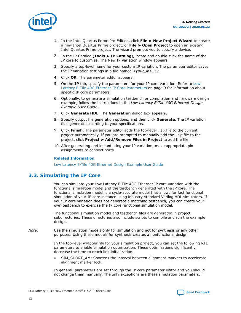
1. In the Intel Quartus Prime Pro Edition, click File ➤ New Project Wizard to createa new Intel Quartus Prime project, or File ➤ Open Project to open an existingIntel Quartus Prime project. The wizard prompts you to specify a device.
2. In the IP Catalog (Tools ➤ IP Catalog), locate and double-click the name of theIP core to customize. The New IP Variation window appears.
3. Specify a top-level name for your custom IP variation. The parameter editor savesthe IP variation settings in a file named <your_ip>.ip.
4. Click OK. The parameter editor appears.
5. On the IP tab, specify the parameters for your IP core variation. Refer to LowLatency E-Tile 40G Ethernet IP Core Parameters on page 9 for information aboutspecific IP core parameters.
6. Optionally, to generate a simulation testbench or compilation and hardware designexample, follow the instructions in the Low Latency E-Tile 40G Ethernet DesignExample User Guide.
7. Click Generate HDL. The Generation dialog box appears.
8. Specify output file generation options, and then click Generate. The IP variationfiles generate according to your specifications.
9. Click Finish. The parameter editor adds the top-level .ip file to the currentproject automatically. If you are prompted to manually add the .ip file to theproject, click Project ➤ Add/Remove Files in Project to add the file.
10. After generating and instantiating your IP variation, make appropriate pinassignments to connect ports.
Related Information
Low Latency E-Tile 40G Ethernet Design Example User Guide
3.3. Simulating the IP Core
You can simulate your Low Latency E-Tile 40G Ethernet IP core variation with thefunctional simulation model and the testbench generated with the IP core. Thefunctional simulation model is a cycle-accurate model that allows for fast functionalsimulation of your IP core instance using industry-standard Verilog HDL simulators. Ifyour IP core variation does not generate a matching testbench, you can create yourown testbench to exercise the IP core functional simulation model.
The functional simulation model and testbench files are generated in projectsubdirectories. These directories also include scripts to compile and run the exampledesign.
Note: Use the simulation models only for simulation and not for synthesis or any otherpurposes. Using these models for synthesis creates a nonfunctional design.
In the top-level wrapper file for your simulation project, you can set the following RTLparameters to enable simulation optimization. These optimizations significantlydecrease the time to reach link initialization.
• SIM_SHORT_AM: Shortens the interval between alignment markers to acceleratealignment marker lock.
In general, parameters are set through the IP core parameter editor and you shouldnot change them manually. The only exceptions are these simulation parameters.
3. Getting Started
UG-20272 | 2020.06.22
Low Latency E-Tile 40G Ethernet Intel® FPGA IP User Guide Send Feedback
12

To set the simulation optimization parameters on the PHY blocks, add the followinglines to the top-level wrapper file:
defparam <dut instance>.SIM_SHORT_AM = 1'b1;
Note: You can use the example testbench as a guide for setting the simulation parameters inyour own simulation environment. These lines are already present in the Intel-provided testbench for the IP core.
Related Information
• Simulating Intel FPGA IP Cores
• Low Latency E-Tile 40G Ethernet Design Example User GuideDescribes the Low Latency E-Tile 40G Ethernet testbench and design exampleand how to simulate the testbench.
3.4. Generated File Structure
The Intel Quartus Prime Pro Edition software generates the following IP core outputfile structure.
For information about the file structure of the design example, refer to the LowLatency E-Tile 40G Ethernet Design Example User Guide.
3. Getting Started
UG-20272 | 2020.06.22
Send Feedback Low Latency E-Tile 40G Ethernet Intel® FPGA IP User Guide
13
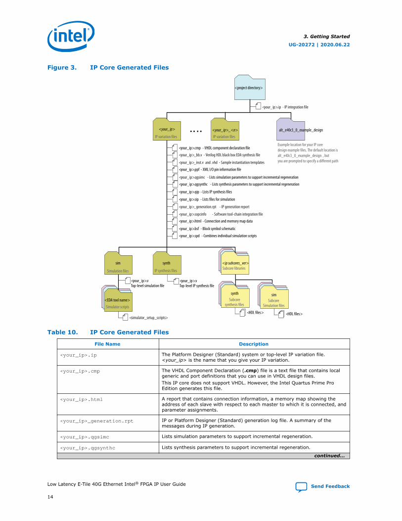
Figure 3. IP Core Generated Files
<your_ip>.cmp - VHDL component declaration file
<your_ip>.ppf - XML I/O pin information file
<your_ip>.qip - Lists IP synthesis files
<your_ip>.sip - Lists files for simulation
<your_ip>.v Top-level IP synthesis file
<your_ip>.v Top-level simulation file
<simulator_setup_scripts>
<your_ip>.ip - IP integration file
<your_ip>_bb.v - Verilog HDL black box EDA synthesis file
<your_ip>_inst.v and .vhd - Sample instantiation templates
<your_ip>_generation.rpt - IP generation report
<your_ip>.sopcinfo - Software tool-chain integration file
<your_ip>.html - Connection and memory map data
<your_ip>.bsf - Block symbol schematic
<your_ip>.spd - Combines individual simulation scripts
<project directory>
<your_ip>
IP variation files
alt_e40c3_0_example_design
Example location for your IP core design example files. The default location is alt_e40c3_0_example_design , butyou are prompted to specify a different path
sim
Simulation files
synth
IP synthesis files
<EDA tool name>
Simulator scripts
<ip subcores_ver>Subcore libraries
simSubcore
Simulation files
synthSubcore
synthesis files
<HDL files><HDL files>
<your_ip>_<n>
IP variation files
<your_ip>.qgsynthc - Lists synthesis parameters to support incremental regeneration
<your_ip>.qgsimc - Lists simulation parameters to support incremental regeneration
Table 10. IP Core Generated Files
File Name Description
<your_ip>.ip The Platform Designer (Standard) system or top-level IP variation file.<your_ip> is the name that you give your IP variation.
<your_ip>.cmp The VHDL Component Declaration (.cmp) file is a text file that contains localgeneric and port definitions that you can use in VHDL design files.This IP core does not support VHDL. However, the Intel Quartus Prime ProEdition generates this file.
<your_ip>.html A report that contains connection information, a memory map showing theaddress of each slave with respect to each master to which it is connected, andparameter assignments.
<your_ip>_generation.rpt IP or Platform Designer (Standard) generation log file. A summary of themessages during IP generation.
<your_ip>.qgsimc Lists simulation parameters to support incremental regeneration.
<your_ip>.qgsynthc Lists synthesis parameters to support incremental regeneration.
continued...
3. Getting Started
UG-20272 | 2020.06.22
Low Latency E-Tile 40G Ethernet Intel® FPGA IP User Guide Send Feedback
14

File Name Description
<your_ip>.qip Contains all the required information about the IP component to integrate andcompile the IP component in the Intel Quartus Prime Pro Edition software.
<your_ip>.csv Contains information about the upgrade status of the IP component.
<your_ip>.bsf A Block Symbol File (.bsf) representation of the IP variation for use in IntelQuartus Prime Block Diagram Files (.bdf).
<your_ip>.spd Required input file for ip-make-simscript to generate simulation scripts forsupported simulators. The .spd file contains a list of files generated forsimulation, along with information about memories that you can initialize.
<your_ip>.ppf The Pin Planner File (.ppf) stores the port and node assignments for IPcomponents created for use with the Pin Planner.
<your_ip>_bb.v You can use the Verilog black-box (_bb.v) file as an empty module declarationfor use as a black box.
<your_ip>.sip Contains information required for NativeLink simulation of IP components. Youmust add the .sip file to your Intel Quartus Prime project.
<your_ip>_inst.v and _inst.vhd HDL example instantiation template. You can copy and paste the contents ofthis file into your HDL file to instantiate the IP variation.This IP core does not support VHDL. However, the Intel Quartus Prime ProEdition generates the _inst.vhd file.
<your_ip>.regmap If IP contains register information, .regmap file generates. The .regmap filedescribes the register map information of master and slave interfaces. Thisenables register display views and user customizable statistics in the SystemConsole.
<your_ip>.svd Allows hard processor system (HPS) System Debug tools to view the registermaps of peripherals connected to HPS within a Platform Designer (Standard)system.During synthesis, the .svd files for slave interfaces visible to System Consolemasters are stored in the .sof file in the debug section. System Console readsthis section, which Platform Designer (Standard) can query for register mapinformation. For system slaves, Platform Designer (Standard) can access theregisters by name.
<your_ip>.v HDL files that instantiate each submodule or child IP core for synthesis orsimulation.
mentor/ Contains a ModelSim* script msim_setup.tcl to set up and run a simulation.
aldec/ Contains a Riviera-PRO script rivierapro_setup.tcl to setup and run asimulation.This IP core does not support simulation with the Aldec Riviera-PRO simulator.However, the Intel Quartus Prime Pro Edition generates this directory.
synopsys/vcs/
synopsys/vcsmx/
Contains a shell script vcs_setup.sh to set up and run a VCS* simulation.Contains a shell script vcsmx_setup.sh and synopsys_ sim.setup file toset up and run a VCS MX simulation.
cadence/ Contains a shell script ncsim_setup.sh and other setup files to set up andrun an NCSIM simulation.
submodules/ Contains HDL files for the IP core submodule.
<child IP cores>/ For each generated child IP core directory, Platform Designer (Standard)generates synth/ and sim/ sub-directories.
Related Information
Low Latency E-Tile 40G Ethernet Design Example User GuideInformation about the Low Latency E-Tile 40G Ethernet design example filestructure.
3. Getting Started
UG-20272 | 2020.06.22
Send Feedback Low Latency E-Tile 40G Ethernet Intel® FPGA IP User Guide
15
3.5. Integrating Your IP Core in Your Design
3.5.1. Pin Assignments
When you integrate your Low Latency E-Tile 40G Ethernet core instance in yourdesign, you must make appropriate pin assignments. While compiling the IP corealone, you can create virtual pins to avoid making specific pin assignments for top-level signals. When you are ready to map the design to hardware, you can change tothe correct pin assignments.
Related Information
Intel Quartus Prime HelpFor information about the Intel Quartus Prime software, including virtual pins.
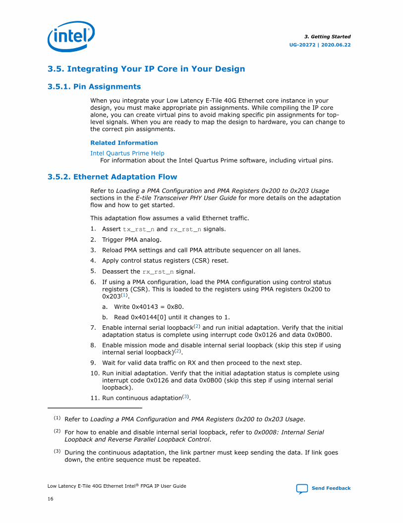
3.5.2. Ethernet Adaptation Flow
Refer to Loading a PMA Configuration and PMA Registers 0x200 to 0x203 Usagesections in the E-tile Transceiver PHY User Guide for more details on the adaptationflow and how to get started.
This adaptation flow assumes a valid Ethernet traffic.
1. Assert tx_rst_n and rx_rst_n signals.
2. Trigger PMA analog.
3. Reload PMA settings and call PMA attribute sequencer on all lanes.
4. Apply control status registers (CSR) reset.
5. Deassert the rx_rst_n signal.
6. If using a PMA configuration, load the PMA configuration using control statusregisters (CSR). This is loaded to the registers using PMA registers 0x200 to0x203(1).
a. Write 0x40143 = 0x80.
b. Read 0x40144[0] until it changes to 1.
7. Enable internal serial loopback(2) and run initial adaptation. Verify that the initialadaptation status is complete using interrupt code 0x0126 and data 0x0B00.
8. Enable mission mode and disable internal serial loopback (skip this step if usinginternal serial loopback)(2).
9. Wait for valid data traffic on RX and then proceed to the next step.
10. Run initial adaptation. Verify that the initial adaptation status is complete usinginterrupt code 0x0126 and data 0x0B00 (skip this step if using internal serialloopback).
11. Run continuous adaptation(3).
(1) Refer to Loading a PMA Configuration and PMA Registers 0x200 to 0x203 Usage.
(2) For how to enable and disable internal serial loopback, refer to 0x0008: Internal SerialLoopback and Reverse Parallel Loopback Control.
(3) During the continuous adaptation, the link partner must keep sending the data. If link goesdown, the entire sequence must be repeated.
3. Getting Started
UG-20272 | 2020.06.22
Low Latency E-Tile 40G Ethernet Intel® FPGA IP User Guide Send Feedback
16

12. Deassert the rx_rst_n signal.
13. Optional: Verify that the link status signal rx_aligned transitions high.
14. Send packets.
3.5.3. Placement Settings for the Low Latency E-Tile 40G Ethernet Core
The Quartus Prime software provides the options to specify design partitions and LogicLock (Standard) or Logic Lock regions for incremental compilation, to controlplacement on the device. To achieve timing closure for your design, you might need toprovide floorplan guidelines using one or both of these features.
The appropriate floorplan is always design-specific, and depends on your design.
Related Information
Intel Quartus Prime Pro Edition User Guide: Design ConstraintsDescribes incremental compilation, design partitions, and Logic Lock regions.
3.6. Low Latency E-Tile 40G Ethernet IP Core Testbench
Intel provides a compilation-only example design and a testbench with most variationsof the Low Latency E-Tile 40G Ethernet IP core.
To generate the testbench, you must first set the parameter values for the IP corevariation you intend to generate. If you do not set the parameter values identically,the testbench you generate might not exercise the IP core variation you generate. Ifyour IP core variation does not meet the criteria for a testbench, the generationprocess does not create a testbench.
3.6.1. Understanding the Testbench Behavior
The testbenches send traffic through the IP core in transmit-to-receive loopbackmode, exercising the transmit side and receive side of the IP core in the same dataflow. These testbenches send traffic to allow the Ethernet lanes to lock, and then sendpackets to the transmit client data interface and check the data as it returns throughthe receive client data interface.
The Low Latency E-Tile 40G Ethernet IP core implements virtual lanes as defined inthe IEEE 802.3ba-2012 Ethernet Standard. The IP core is fixed at four virtual lanes;the four virtual lanes are typically transmitted over four 10 Gbps physical lanes. Whenthe lanes arrive at the receiver the lane streams are in an undefined order. Each lanecarries a periodic PCS-VLANE alignment tag to restore the original ordering. Thesimulation establishes a random permutation of the physical lanes that is used for theremainder of the simulation.
Within each virtual lane stream, the data is 64B/66B encoded. Each word has twoframing bits which are always either 01 or 10, never 00 or 11. The RX logic uses thispattern to lock onto the correct word boundaries in each serial stream. The process isprobabilistic due to false locks on the pseudo-random scrambled stream.
Both the word lock and the alignment marker lock implement hysteresis as defined inthe IEEE Standard for Ethernet, Section 4. Multiple successes are required to acquirelock and multiple failures are required to lose lock. The “fully locked” messages in thesimulation log indicate the point at which a physical lane has successfully identifiedthe word boundary and virtual lane assignment.
3. Getting Started
UG-20272 | 2020.06.22
Send Feedback Low Latency E-Tile 40G Ethernet Intel® FPGA IP User Guide
17

In the event of a catastrophic error, the RX PCS automatically attempts to reacquirealignment. The MAC properly identifies errors in the datastream.
3.7. Compiling the Full Design and Programming the FPGA
You can use the Start Compilation command on the Processing menu in the IntelQuartus Prime software to compile your design. After successfully compiling yourdesign, program the targeted Intel FPGA with the Programmer and verify the design inhardware.
Note: The Low Latency E-Tile 40G Ethernet core design example synthesis directories includeSynopsys Constraint (.sdc) files that you can copy and modify for your own design.
Related Information
• Incremental Compilation for Hierarchical and Team-Based Design
• Programming Intel Devices
• Low Latency E-Tile 40G Ethernet Design Example User Guide
3. Getting Started
UG-20272 | 2020.06.22
Low Latency E-Tile 40G Ethernet Intel® FPGA IP User Guide Send Feedback
18
4. Functional Description
4.1. Low Latency E-Tile 40G Ethernet Core Functional Description
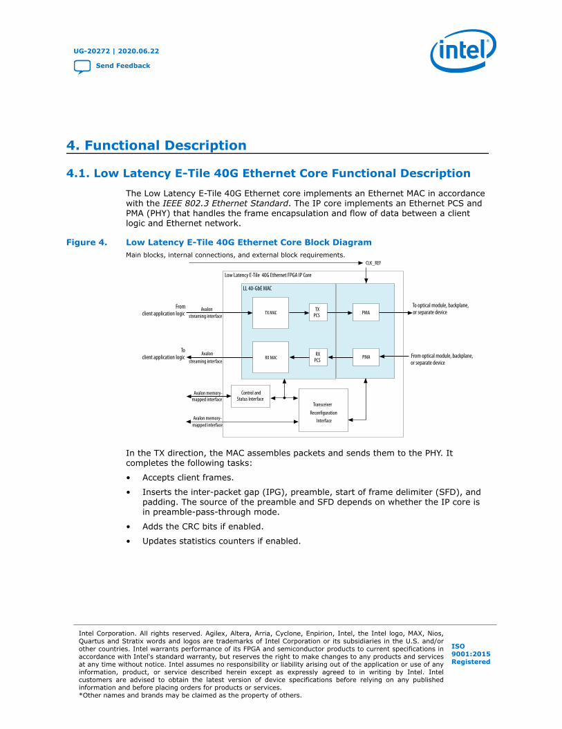
The Low Latency E-Tile 40G Ethernet core implements an Ethernet MAC in accordancewith the IEEE 802.3 Ethernet Standard. The IP core implements an Ethernet PCS andPMA (PHY) that handles the frame encapsulation and flow of data between a clientlogic and Ethernet network.
Figure 4. Low Latency E-Tile 40G Ethernet Core Block DiagramMain blocks, internal connections, and external block requirements.
Low Latency E-Tile 40G Ethernet FPGA IP Core
TXFIFO PMA
PMARXPCS
TXPCS
Avalon
Avalon
Control andStatus Interface
Transceiver
ReconfigurationInterface
Avalon memory-
CLK_REF
LL 40-GbE MAC
To optical module, backplane,or separate device
From optical module, backplane,or separate device
Fromclient application logic
Toclient application logic
TX MAC
RX MAC
streaming interface
streaming interface
mapped interface
Avalon memory-mapped interface
In the TX direction, the MAC assembles packets and sends them to the PHY. Itcompletes the following tasks:
• Accepts client frames.
• Inserts the inter-packet gap (IPG), preamble, start of frame delimiter (SFD), andpadding. The source of the preamble and SFD depends on whether the IP core isin preamble-pass-through mode.
• Adds the CRC bits if enabled.
• Updates statistics counters if enabled.
UG-20272 | 2020.06.22
Send Feedback
Intel Corporation. All rights reserved. Agilex, Altera, Arria, Cyclone, Enpirion, Intel, the Intel logo, MAX, Nios,Quartus and Stratix words and logos are trademarks of Intel Corporation or its subsidiaries in the U.S. and/orother countries. Intel warrants performance of its FPGA and semiconductor products to current specifications inaccordance with Intel's standard warranty, but reserves the right to make changes to any products and servicesat any time without notice. Intel assumes no responsibility or liability arising out of the application or use of anyinformation, product, or service described herein except as expressly agreed to in writing by Intel. Intelcustomers are advised to obtain the latest version of device specifications before relying on any publishedinformation and before placing orders for products or services.*Other names and brands may be claimed as the property of others.
ISO9001:2015Registered
In the RX direction, the PMA passes frames to the PCS that sends them to the MAC.The MAC completes the following tasks:
• Performs CRC and malformed packet checks.
• Updates statistics counters if enabled.
• Strips out the CRC, preamble, and SFD.
• Passes the remainder of the frame to the client.
In preamble pass-through mode, the MAC passes on the preamble and SFD to theclient instead of stripping them out. In RX CRC pass-through mode, the MAC passeson the CRC bytes to the client and asserts the end-of-packet signal in the same clockcycle as the final CRC byte.
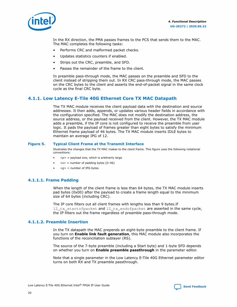
4.1.1. Low Latency E-Tile 40G Ethernet Core TX MAC Datapath
The TX MAC module receives the client payload data with the destination and sourceaddresses. It then adds, appends, or updates various header fields in accordance withthe configuration specified. The MAC does not modify the destination address, thesource address, or the payload received from the client. However, the TX MAC moduleadds a preamble, if the IP core is not configured to receive the preamble from userlogic. It pads the payload of frames greater than eight bytes to satisfy the minimumEthernet frame payload of 46 bytes. The TX MAC module inserts IDLE bytes tomaintain an average IPG of 12.
Figure 5. Typical Client Frame at the Transmit InterfaceIllustrates the changes that the TX MAC makes to the client frame. This figure uses the following notationalconventions:
• <p> = payload size, which is arbitrarily large
• <s> = number of padding bytes (0–46)
• <g> = number of IPG bytes
4.1.1.1. Frame Padding
When the length of the client frame is less than 64 bytes, the TX MAC module insertspad bytes (0x00) after the payload to create a frame length equal to the minimumsize of 64 bytes (including CRC).
The IP core filters out all client frames with lengths less than 9 bytes.Ifl2_tx_startofpacket and l2_tx_endofpacket are asserted in the same cycle,the IP filters out the frame regardless of preamble pass-through mode.
4.1.1.2. Preamble Insertion
In the TX datapath the MAC prepends an eight-byte preamble to the client frame. Ifyou turn on Enable link fault generation, this MAC module also incorporates thefunctions of the reconciliation sublayer (RS).
The source of the 7-byte preamble (including a Start byte) and 1-byte SFD dependson whether you turn on Enable preamble passthrough in the parameter editor.
Note that a single parameter in the Low Latency E-Tile 40G Ethernet parameter editorturns on both RX and TX preamble passthrough.
4. Functional Description
UG-20272 | 2020.06.22
Low Latency E-Tile 40G Ethernet Intel® FPGA IP User Guide Send Feedback
20
4.1.1.3. Inter-Packet Gap Generation and Insertion
The TX MAC maintains the minimum inter-packet gap (IPG) between transmittedframes required by the IEEE 802.3 Ethernet standard. The deficit idle counter (DIC)maintains the average IPG of 12 bytes.
4.1.1.4. Frame Check Sequence (CRC-32) Insertion
The TX MAC computes and inserts a CRC32 checksum in the transmitted MAC frame.The frame check sequence (FCS) field contains a 32-bit CRC value. The MAC computesthe CRC32 over the frame bytes that include the source address, destination address,length, data, and pad (if applicable). The CRC checksum computation excludes thepreamble, SFD, and FCS. The encoding is defined by the following generatingpolynomial:
FCS(X) = X32 +X26 +X23 +X22 +X16 +X12 +X11 +X10 +X8 +X7 +X5 +X4 +X2 +X1 +1
CRC bits are transmitted with MSB (X32) first.
You can configure your IP core TX MAC to implement TX CRC insertion or not, byturning Enable TX CRC insertion on or off in the IP core parameter editor. Bydefault, the CRC insertion feature is enabled.
In CRC pass-through mode, the l2_tx_endofpacket and l2_rx_endofpacketalong with l2_tx_empty and l2_rx_empty point to the last byte of Frame CheckSequence (FCS).
Note: In TX CRC pass-through mode, you must provide frames with at least 64 bytes. IfFlow control mode is enabled, the IP core generates and inserts the CRC for flowcontrol packets.
If you have not selected the CRC pass-through mode, the l2_tx_endofpacket andl2_rx_endofpacket along with l2_tx_empty and l2_rx_empty point to the lastbyte before the first FCS.
Note: The TX CRC insertion requires to set Flow control mode to 1.
4.1.2. Low Latency E-Tile 40G Ethernet Core RX MAC Datapath
The RX MAC receives Ethernet frames and forwards the payload with relevant headerbytes to the client after performing some MAC functions on header bytes. The RX MACprocesses all incoming valid frames.
4. Functional Description
UG-20272 | 2020.06.22
Send Feedback Low Latency E-Tile 40G Ethernet Intel® FPGA IP User Guide
21

Figure 6. Flow of Client Frame With Preamble Pass-Through Turned OnThis figure uses the following notational conventions:
• <p> = payload size, which is arbitrarily large.
• <s> = number of padding bytes (0–46).
Client - MAC Rx Interface
Ethernet MAC Frame
Client FrameDestination Addr[47:0]
Source Addr[47:0]
Type/Length[15:0]
Payload[<p>-1:0]
Destination Addr[47:0]SFD[7:0]
Preamble [47:0]
CRC32[31:0]
CRC32[31:0]
PAD [<s>-1:0]
PAD [<s>-1:0]Source
Addr[47:0]Start[7:0]
SFD[7:0]Preamble [47:0]Start[7:0]
EFD[7:0]
If CRC forwarding is turned on
Payload[<p>-1:0]
Type/Length[15:0]
Figure 7. Flow of Client Frame With Preamble Pass-Through Turned OffThis figure uses the following notational conventions:
• <p> = payload size, which is arbitrarily large.
• <s> = number of padding bytes (0–46).
Client - MAC Rx Interface
Client Frame on l<n>_rx_dataDestination Addr[47:0]
Source Addr[47:0]
Type/Length[15:0]
Payload[<p>-1:0]
Destination Addr[47:0]
SFD[7:0]Preamble [47:0]
CRC32[31:0]
CRC32[31:0]
PAD [<s>-1:0]
PAD [<s>-1:0]Source
Addr[47:0]Start[7:0] EFD[7:0]
If CRC forwarding is turned on
Payload[<p>-1:0]
Type/Length[15:0]
Ethernet MAC Frame
4.1.2.1. IP Core Preamble Processing
If you turn on Enable preamble passthrough in the parameter editor, the RX MACforwards preamble bytes. The TX MAC requires the preamble bytes to be included inthe frames at the Avalon Streaming interface.
Note that a single parameter in the Low Latency E-Tile 40G Ethernet parameter editorturns on both RX and TX preamble passthrough.
4.1.2.2. IP Core Strict SFD Checking
The Low Latency E-Tile 40G Ethernet core RX MAC checks all incoming packets for acorrect Start byte (0xFB). If you turn on Enable Strict SFD check in the Low LatencyE-Tile 40G Ethernet parameter editor, you enable the RX MAC to check the incomingpreamble and SFD for the following values:
• SFD = 0xD5
• Preamble = 0x555555555555
The RX MAC checks one or both of these values depending on the values in bits [4:3]of the RXMAC_CONTROL register at offset 0x50A.
4. Functional Description
UG-20272 | 2020.06.22
Low Latency E-Tile 40G Ethernet Intel® FPGA IP User Guide Send Feedback
22

Table 11. Strict SFD Checking Configuration
Enable Strict SFDcheck
0x50A[4]: PreambleCheck
0x50A[3]: SFD Check Fields Checked Behavior if CheckFails
Off Don't Care Don't Care Start byte IP core does notrecognize amalformed Start byteas a Start byte
On 0 0 Start byte
0 1 Start byte and SFD IP Core drops thepacket
1 0 Start byte andpreamble
1 1 Start byte andpreamble and SFD
4.1.2.3. Length/Type Field Processing
This two-byte header represents either the length of the payload or the type of MACframe.
• Length/type <= 0x5DC (1500) —The field represents the payload length of a basicEthernet frame. The MAC TX/RX continues to check the frame and payloadlengths.
• 0x5DC (1500) < Length/type < 0x600 (1536) — The frames with payloads size inthis range are not standard basic Ethernet frames, nor they are legal controlpackets. The payload length is not checked for this kind of packets.
• Length/type >= 0x600—The field represents the frame type. The following frametypes are possible:
— Length/type = 0x8100—VLAN or stacked VLAN tagged frames. The MAC RXcontinues to check the frame and payload lengths.
— Length/type = 0x8808—Control frames. The next two bytes are the Opcodefield that indicates the type of control frame. For pause frames (Opcode =0x0001) and PFC frames (Opcode = 0x0101), the MAC RX proceeds withpause frame processing.
— For other field values, the MAC RX forwards the receive frame to the client.
4.1.2.3.1. Length Checking
The MAC function checks the frame and payload lengths of basic, VLAN tagged, andstacked VLAN tagged frames.
The IP core checks that the frame length is valid—is neither undersized nor oversized.A valid frame length is at least 64 (0x40) bytes and does not exceed the followingmaximum value for the different frame types:
• Basic frames—The number of bytes specified in the MAX_RX_SIZE_CONFIGregister.
• VLAN tagged frames—The value specified in the MAX_RX_SIZE_CONFIG registerplus four bytes.
• Stacked VLAN tagged frames—The value specified in the MAX_RX_SIZE_CONFIGregister plus eight bytes.
4. Functional Description
UG-20272 | 2020.06.22
Send Feedback Low Latency E-Tile 40G Ethernet Intel® FPGA IP User Guide
23
If the length/type field in a basic MAC frame or the client length/type field in a VLANtagged frame has a value less than 0x600, the IP core also checks the payload length.The IP core keeps track of the payload length as it receives a frame, and checks thelength against the relevant frame field. The payload length is valid if it satisfies thefollowing conditions:
The RX MAC does not drop frames with invalid length or invalid payload length. If theframe or payload length is not valid, the MAC function asserts output error bits.
If the length field value is greater than the actual payload length, the IP core asserts .If the length field value is less than the actual payload length, the MAC RX considersthe frame to have excessive padding and does not assert .
4.1.2.4. RX CRC Checking and Dynamic Forwarding
By default, the RX MAC strips off the CRC bytes before forwarding the packet to theMAC client. You can configure the core to retain the RX CRC and forward it to theclient by updating the MAC_CRC_CONFIG register.
4.1.3. Link Fault Signaling Interface
Link fault signaling reflects the health of the link. It operates between the remoteEthernet device Reconciliation Sublayer (RS) and the local Ethernet device RS. Thelink fault modules communicate status during the interframe period.
For unidirectional fault signaling, the core implements Clause 66 of the IEEE802.3-2012 Ethernet Standard.
Local Fault (LF)
If an Ethernet PHY sublayer detects a fault that makes the link unreliable, it notifiesthe RS of the local fault condition. If unidirectional is not enabled, the core followsClause 46. The RS stops sending MAC data, and continuously generates a remote faultstatus on the TX datapath. After a local fault is detected, the RX PCS modifies the MIIdata and control to send local fault sequence ordered sets. Refer to Link FaultSignaling Based On Configuration and Status below.
The RX PCS cannot recognize the link fault under the following conditions:
• The RX PCS is not fully aligned.
• The bit error rate (BER) is high.
Remote Fault (RF)
If unidirectional is not enabled, the core follows Clause 46. If the RS receives a remotefault status, the TX datapath stops sending MAC data and continuously generates idlecontrol characters. If the RS stops receiving fault status messages, it returns tonormal operation, sending MAC client data. Refer to Link Fault Signaling Based OnConfiguration and Status below.
Link Status Signals
The MAC RX generates two link fault signals: local_fault_status andremote_fault_status.
4. Functional Description
UG-20272 | 2020.06.22
Low Latency E-Tile 40G Ethernet Intel® FPGA IP User Guide Send Feedback
24
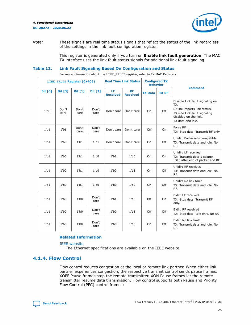
Note: These signals are real time status signals that reflect the status of the link regardlessof the settings in the link fault configuration register.
This register is generated only if you turn on Enable link fault generation. The MACTX interface uses the link fault status signals for additional link fault signaling.
Table 12. Link Fault Signaling Based On Configuration and StatusFor more information about the LINK_FAULT register, refer to TX MAC Registers.
LINK_FAULT Register (0x405) Real Time Link Status Configured TXBehavior
CommentBit [0] Bit [3] Bit [1] Bit [2] LF
ReceivedRF
Received TX Data TX RF
1'b0 Don'tcare
Don'tcare
Don'tcare Don’t care Don’t care On Off
Disable Link fault signaling onTX.RX still reports link status.TX side Link fault signalingdisabled on the link.TX data and idle.
1'b1 1'b1 Don'tcare
Don'tcare Don't care Don't care Off On
Force RF.TX: Stop data. Transmit RF only
1'b1 1'b0 1'b1 1'b1 Don't care Don't care On OffUnidir: Backwards compatible.TX: Transmit data and idle. NoRF.
1'b1 1'b0 1'b1 1'b0 1'b1 1'b0 On OnUnidir: LF received.TX: Transmit data 1 columnIDLE after end of packet and RF
1'b1 1'b0 1'b1 1'b0 1'b0 1'b1 On OffUnidir: RF receivesTX: Transmit data and idle. NoRF.
1'b1 1'b0 1'b1 1'b0 1'b0 1'b0 On OffUnidir: No link faultTX: Transmit data and idle. NoRF.
1'b1 1'b0 1'b0 Don'tcare 1'b1 1'b0 Off On
Bidir: LF receivedTX: Stop data. Transmit RFonly.
1'b1 1'b0 1'b0 Don'tcare 1'b0 1'b1 Off Off
Bidir: RF receivedTX: Stop data. Idle only. No RF.
1'b1 1'b0 1'b0 Don’tcare 1'b0 1'b0 On Off
Bidir: No link faultTX: Transmit data and idle. NoRF.
Related Information
IEEE websiteThe Ethernet specifications are available on the IEEE website.
4.1.4. Flow Control
Flow control reduces congestion at the local or remote link partner. When either linkpartner experiences congestion, the respective transmit control sends pause frames.XOFF Pause frames stop the remote transmitter. XON Pause frames let the remotetransmitter resume data transmission. Flow control supports both Pause and PriorityFlow Control (PFC) control frames:
4. Functional Description
UG-20272 | 2020.06.22
Send Feedback Low Latency E-Tile 40G Ethernet Intel® FPGA IP User Guide
25

• IEEE 802.3 flow control—implements the IEEE 802.3 Annex 31B standard tomanage congestion. This flow control is a mechanism to manage congestion at thelocal or remote partner. When the receiving device experiences congestion, itsends an XOFF pause frame to the emitting device to instruct the emitting deviceto stop sending data for a duration specified by the congested receiver. Datatransmission resumes when the emitting device receives an XON pause frame(pause quanta = zero) or when the timer expires.
• Priority-based flow control (PFC)—implements the IEEE 802.1Qbb standard. PFCmanages congestion based on priority levels. It supports up to 8 priority queues.When the receiving device experiences congestion on a priority queue, it sends aPFC frame requesting the emitting device to stop transmission on the priorityqueue for a duration specified by the congested receiver. When the receivingdevice is ready to receive transmission on the priority queue again, it sends a PFCframe instructing the emitting device to resume transmission on the priorityqueue.
Figure 8. Flow Control Module Conceptual OverviewThe flow control module acts as a buffer between client logic and the TX and RX MAC.
MAC(Core)
FrameArbiter PHY
CSR
TX Pause/PFCFrame Control
Pause/PFC BeatConversion
RX Pause/PFCFrame Control
TX User Interface
Pause Duration
RX User InterfaceFlow Control
TX ClockRX Clock
TX ResetRX Reset
4. Functional Description
UG-20272 | 2020.06.22
Low Latency E-Tile 40G Ethernet Intel® FPGA IP User Guide Send Feedback
26

Flow Control includes the following features:
• Pause or PFC frame generation and transmission:
— Configurable selection of standard or priority-based flow control
— Programmable 1- or 2-bit XON/XOFF request mode
— In 2-bit request mode, programmable selection of register or signal-basedcontrol
— Programmable per-queue XOFF frame separation
— Programmable destination and source addresses in outgoing pause and PFCframes
— Programmable pause and PFC quanta
• Client versus Pause or PFC frame transmission based on a priority-basedarbitration scheme with frame-type indication for external downstream logic
• Stopping the next client frame transmission on the reception of a valid Pauseframe
• Stopping the per queue client frame transmission on the reception of a valid PFCframe from the client. Includes per-queue PFC Pause quanta duration indicator
• Pause or PFC frame reception and decode:
— Programmable destination address for filtering incoming pause and PFC frames
— Configurable Pause or PFC per-queue enable, directing the IP core to ignoreincoming pause frames on disabled queues
— Per-queue client frame transmission pause duration indicator
4.1.4.1. TX Pause/PFC Flow Control Transmission
An XON/XOFF request triggers the IP core to transmit a Pause or PFC flow controlframe on the Ethernet link. You can control XON/XOFF requests using the TX flowcontrol registers or the pause_insert_tx0 and pause_insert_tx1 input signals.
You can specify whether the IP core accepts XON/XOFF requests in 1-bit or 2-bitformat by updating the TX Flow Control CSR XON/XOFF Request register field.By default, the IP core assumes 1-bit requests.
4.1.4.2. XON/XOFF Pause Frames
The sender transmits a PFC frame with the specified PFC pause quanta value when itreceives an XOFF request. If an enabled priority queue is in the XOFF condition, a newPFC frame is transmitted after the minimum time gap. You specify the minimum timegap in the per priority queue TX Flow Control Signal XOFF Request HoldQuanta register. The minimum time gap between two consecutive PFC frames is 1pause quanta or 512-bit times. PFC frame transmission ends when none of the PFCinterfaces of all enabled priority queues is requesting PFC frames.
A transition from XOFF to XON in any enabled priority queue triggers the IP core totransmit a PFC frame with pause quanta of 0 for the associated priority queue. The IPcore sends a single XON flow control frame. In the rare case that the XON frame islost or corrupted, the remote partner should still be able to resume transmission. Theremote partner resumes transmission after the duration specified in the previous XOFFflow control frame expires.
4. Functional Description
UG-20272 | 2020.06.22
Send Feedback Low Latency E-Tile 40G Ethernet Intel® FPGA IP User Guide
27
In the case of standard flow control, the IP core transmits Pause frames instead of PFCframes. The transmission behavior is identical.
When the IP core is in standard flow control mode and receives a Pause frame, the IPcore stops processing TX client data, either immediately or at the next frameboundary. Client data transmission resumes when all of the following conditions aretrue:
• The time specified by the pause quanta has elapsed and there is no new quantavalue
• A valid pause frame with 0 pause duration has been received
A Pause frame has no effect if the associated TX Flow Control Enable register bitis set to disable XON and XOFF flow control.
4.2. User Interface to Ethernet Transmission
The IP core reverses the bit stream for transmission per Ethernet requirements. Thetransmitter handles the insertion of the inter-packet gap, frame delimiters, andpadding with zeros as necessary. The transmitter also handles FCS computation andinsertion.
The IP core transmits complete packets. After transmission begins, it must completewith no IDLE insertions. Between the end of one packet and the beginning of the nextpacket, the data input is not considered and the transmitter sends IDLE characters. Anunbounded number of IDLE characters can be sent between packets.
4.2.1. Order of Transmission
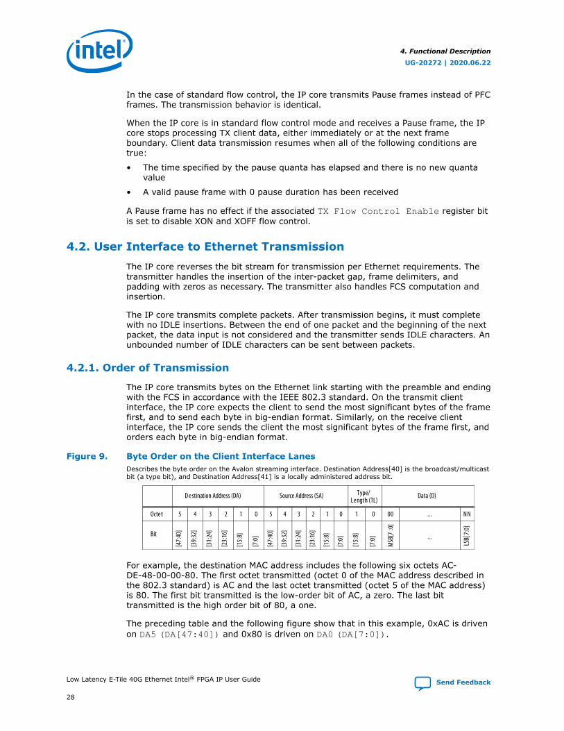
The IP core transmits bytes on the Ethernet link starting with the preamble and endingwith the FCS in accordance with the IEEE 802.3 standard. On the transmit clientinterface, the IP core expects the client to send the most significant bytes of the framefirst, and to send each byte in big-endian format. Similarly, on the receive clientinterface, the IP core sends the client the most significant bytes of the frame first, andorders each byte in big-endian format.
Figure 9. Byte Order on the Client Interface LanesDescribes the byte order on the Avalon streaming interface. Destination Address[40] is the broadcast/multicastbit (a type bit), and Destination Address[41] is a locally administered address bit.
D estination Address (DA) Source Address (SA) Data (D)Type/Length (TL)
Octet 5 4 3 12 0 5 4 3 012 1 0 00 ... N N
Bit
[47:
40]
[39:
32]
[31:
24]
[23:
16]
[15:
8]
[7:0
]
[47:
40]
[39:
32]
[31:
24]
[23:
16]
[15:
8]
[7:0
]
[15:
8]
[7:0
]
MSB
[7:0
]
...
LSB[
7:0]
For example, the destination MAC address includes the following six octets AC-DE-48-00-00-80. The first octet transmitted (octet 0 of the MAC address described inthe 802.3 standard) is AC and the last octet transmitted (octet 5 of the MAC address)is 80. The first bit transmitted is the low-order bit of AC, a zero. The last bittransmitted is the high order bit of 80, a one.
The preceding table and the following figure show that in this example, 0xAC is drivenon DA5 (DA[47:40]) and 0x80 is driven on DA0 (DA[7:0]).
4. Functional Description
UG-20272 | 2020.06.22
Low Latency E-Tile 40G Ethernet Intel® FPGA IP User Guide Send Feedback
28

4.2.2. Bit Order For TX and RX Datapaths
The TX bit order matches the placement shown in the PCS lanes as illustrated in IEEEStandard for Ethernet, Section 4, Figure 49-5. The RX bit order matches theplacement shown in IEEE Standard for Ethernet, Section 4, Figure 49-6.
Related Information
IEEE websiteThe IEEE Standard for Ethernet, Section 4 is available on the IEEE website.
4. Functional Description
UG-20272 | 2020.06.22
Send Feedback Low Latency E-Tile 40G Ethernet Intel® FPGA IP User Guide
29
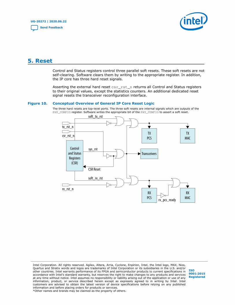
5. ResetControl and Status registers control three parallel soft resets. These soft resets are notself-clearing. Software clears them by writing to the appropriate register. In addition,the IP core has three hard reset signals.
Asserting the external hard reset csr_rst_n returns all Control and Status registersto their original values, except the statistics counters. An additional dedicated resetsignal resets the transceiver reconfiguration interface.
Figure 10. Conceptual Overview of General IP Core Reset LogicThe three hard resets are top-level ports. The three soft resets are internal signals which are outputs of thePHY_CONFIG register. Software writes the appropriate bit of the PHY_CONFIG to assert a soft reset.
TXPCS
TXMAC
RXPCS
RXMAC
tx_rst_n
rx_pcs_ready
Transceivers
csr_rst_n
rx_rst_n
Controland StatusRegisters
(CSR)
soft_tx_rst
sys_rst
soft_rx_rst
CSR Reset
UG-20272 | 2020.06.22
Send Feedback
Intel Corporation. All rights reserved. Agilex, Altera, Arria, Cyclone, Enpirion, Intel, the Intel logo, MAX, Nios,Quartus and Stratix words and logos are trademarks of Intel Corporation or its subsidiaries in the U.S. and/orother countries. Intel warrants performance of its FPGA and semiconductor products to current specifications inaccordance with Intel's standard warranty, but reserves the right to make changes to any products and servicesat any time without notice. Intel assumes no responsibility or liability arising out of the application or use of anyinformation, product, or service described herein except as expressly agreed to in writing by Intel. Intelcustomers are advised to obtain the latest version of device specifications before relying on any publishedinformation and before placing orders for products or services.*Other names and brands may be claimed as the property of others.
ISO9001:2015Registered
The general reset signals reset the following functions:
• soft_tx_rst, tx_rst_n: Resets the IP core in the TX direction. Resets the TXPCS and TX MAC. This reset leads to deassertion of the tx_lanes_stable outputsignal.
• soft_rx_rst, rx_rst_n: Resets the IP core in the RX direction. Resets the RXPCS and RX MAC. This reset leads to deassertion of the rx_pcs_ready outputsignal.
• sys_rst, csr_rst_n: Resets the IP core. Resets the TX and RX MACs, PCS, andtransceivers.
Note: csr_rst_n resets the Control and Status registers, except the statisticscounters. sys_rst does not reset any Control and Status registers.
This reset leads to deassertion of the tx_lanes_stable and rx_pcs_readyoutput signals.
In addition, the synchronous reconfig_reset signal resets the IP core transceiverreconfiguration interface, an Avalon memory-mapped interface. Associated clock is thereconfig_clk, which clocks the transceiver reconfiguration interface.
The CSR register read/write needs to wait at least 2 clock clycles after csr_rst_nassertion.
Related Information
Reset Signals on page 38
5. Reset
UG-20272 | 2020.06.22
Send Feedback Low Latency E-Tile 40G Ethernet Intel® FPGA IP User Guide
31

6. Interfaces and Signal DescriptionsFigure 11. Low Latency E-Tile 40G Ethernet Signals and Interfaces
Low Latency E-Tile 40G Ethernet
clk_statusstatus_addr[15:0]status_readstatus_writestatus_readdata[31:0]status_readdata_validstatus_writedata[31:0]status_waitrequest
clk_txmacl2_tx_data[127:0]l2_tx_preamble[63:0]l2_tx_validl2_tx_startofpacketl2_tx_endofpacketl2_tx_empty[3:0]
l2_tx_readyl2_txstatus_validl2_txstatus_data[39:0]l2_txstatus_error[6:0]
tx_lanes_stablerx_block_lockrx_am_lockrx_pcs_readylocal_fault_statusremote_fault_status
tx_rst_nrx_rst_n
csr_rst_n
reconfig_clkreconfig_resetreconfig_writereconfig_read
reconfig_address[21:0]reconfig_writedata[31:0]reconfig_readdata[31:0]
reconfig_waitrequest
Streaming InterfaceTX Datapath
RX Data path
l2_tx_error
Memory-MappedInterface
MiscellaneousStatus and Debug
Signals
ReconfigurationSignals
ResetSignals
clk_rxmacl2_rx_data[127:0]
l2_rx_validl2_rx_startofpacketl2_rx_endofpacket
l2_rx_empty[3:0]l2_rx_error[5:0]
l2_rxstatus_validl2_rxstatus_data[39:0]
tx_serial[3:0]rx_serial[3:0]
clk_refSerial DataSignals
clk_rx_recoverSynchronous Ethernet
Clock
pause_insert_tx0[7:0]pause_insert_tx1[7:0]pause_receive_rx[7:0]
Flow Control
l2_rx_preamble[63:0]
Avalon Streaming InterfaceAvalon
Avalon
6.1. TX MAC Interface to User Logic
The TX MAC provides an Avalon streaming interface to the FPGA fabric. The datapathcomprises 2, 64-bit words. The minimum packet size is nine bytes.
Table 13. Avalon Streaming TX MAC Interface SignalsAll interface signals are clocked by the clk_txmac clock. The value you specify for Ready latency in the LowLatency E-Tile 40G Ethernet parameter editor is the Avalon streaming interface readyLatency value on thisinterface.
Signal Direction Description
clk_txmac Output The TX clock for the IP core is clk_txmac. The frequency of this clock is312.5 MHz.If you turn on Use external TX MAC PLL in the Low Latency E-Tile 40GEthernet parameter editor, the clk_txmac_in input clock drivesclk_txmac.
l2_tx_data[127:0] Input Data input to MAC. Bit 127 is the MSB and bit 0 is the LSB. Bytes areread in the usual left to right order.
continued...
UG-20272 | 2020.06.22
Send Feedback
Intel Corporation. All rights reserved. Agilex, Altera, Arria, Cyclone, Enpirion, Intel, the Intel logo, MAX, Nios,Quartus and Stratix words and logos are trademarks of Intel Corporation or its subsidiaries in the U.S. and/orother countries. Intel warrants performance of its FPGA and semiconductor products to current specifications inaccordance with Intel's standard warranty, but reserves the right to make changes to any products and servicesat any time without notice. Intel assumes no responsibility or liability arising out of the application or use of anyinformation, product, or service described herein except as expressly agreed to in writing by Intel. Intelcustomers are advised to obtain the latest version of device specifications before relying on any publishedinformation and before placing orders for products or services.*Other names and brands may be claimed as the property of others.
ISO9001:2015Registered

Signal Direction Description
l2_tx_preamble[63:0] Input User preamble data. Available when you turn on Enable preamblepassthrough in the Low Latency E-Tile 40G Ethernet parameter editor.User logic drives the custom preamble data whenl2_tx_startofpacket is asserted.
l2_tx_valid Input When asserted, indicates valid data.
l2_tx_startofpacket Input When asserted, indicates the first byte of a frame. Whenl2_tx_startofpacket is asserted, the MSB of l2_tx_data drivesthe start of packet. Packets that drive l2_tx_startofpacket andl2_tx_endofpacket in the same cycle are ignored.
l2_tx_endofpacket Input When asserted, indicates the end of a packet. Packets that drivel2_tx_startofpacket and l2_tx_endofpacket in the same cycleare ignored.
l2_tx_empty[3:0] Input Specifies the number of empty bytes when l2_tx_endofpacket isasserted.
l2_tx_ready Output When asserted, indicates that the MAC can accept the data. The IP coreasserts the l2_tx_ready signal on clock cycle <n> to indicate thatclock cycle <n + readyLatency> is a ready cycle. The client may onlyassert l2_tx_valid and transfer data during ready cycles.
l2_tx_error Input When asserted in an EOP cycle (while l2_tx_endofpacket isasserted), directs the IP core to insert an error in the packet beforesending it on the Ethernet link.Note: This functionality is not available in the Quartus Prime Pro 17.1
Stratix 10 ES Editions software.
l2_txstatus_valid Output When asserted, indicates that l2_txstatus_data andl2_txstatus_error[6:0] are driving valid data.
l2_txstatus_data[39:0] Output Specifies information about the transmit frame. The following fields aredefined:• [Bit 39]: When asserted, indicates a PFC frame• [Bit 38]: When asserted, indicates a unicast frame• Bit[37]: When asserted, indicates a multicast frame• Bit[36]: When asserted, indicates a broadcast frame• Bit[35]: When asserted, indicates a pause frame• Bit[34]: When asserted, indicates a control frame• Bit[33]: When asserted, indicates a VLAN frame• Bit[32]: When asserted, indicates a stacked VLAN frame• Bits[31:16]: Specifies the frame length from the first byte of the
destination address to the last bye of the FCS• Bits[15:0]: Specifies the payload length
l2_txstatus_error[6:0] Output Specifies the error type in the transmit frame. The following fields aredefined:• Bits[6:3]: Reserved• Bit[2]: Payload length error• Bit[1]: Oversized frame• Bit[0]: Reserved.
6. Interfaces and Signal Descriptions
UG-20272 | 2020.06.22
Send Feedback Low Latency E-Tile 40G Ethernet Intel® FPGA IP User Guide
33
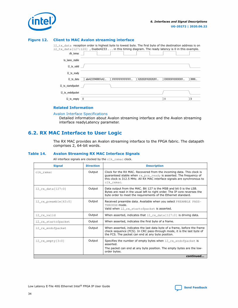
Figure 12. Client to MAC Avalon streaming interfacel2_tx_data reception order is highest byte to lowest byte. The first byte of the destination address is onl2_tx_data[127:120] , 0xabe4233 . . . in this timing diagram. The ready latency is 0 in this example.
abe4233940001e42... 0101010101010101... 0202020102020201... 0303030103030301... 0000...
0 4 0
clk_txmac
tx_lanes_stable
l2_tx_valid
l2_tx_ready
l2_tx_data
l2_tx_startofpacket
l2_tx_endofpacket
l2_tx_empty
Related Information
Avalon Interface SpecificationsDetailed information about Avalon streaming interface and the Avalon streaminginterface readyLatency parameter.
6.2. RX MAC Interface to User Logic
The RX MAC provides an Avalon streaming interface to the FPGA fabric. The datapathcomprises 2, 64-bit words.
Table 14. Avalon Streaming RX MAC Interface SignalsAll interface signals are clocked by the clk_rxmac clock.
Signal Direction Description
clk_rxmac Output Clock for the RX MAC. Recovered from the incoming data. This clock isguaranteed stable when rx_pcs_ready is asserted. The frequency ofthis clock is 312.5 MHz. All RX MAC interface signals are synchronous toclk_rxmac.
l2_rx_data[127:0] Output Data output from the MAC. Bit 127 is the MSB and bit 0 is the LSB.Bytes are read in the usual left to right order. The IP core reverses thebyte order to meet the requirements of the Ethernet standard.
l2_rx_preamble[63:0] Output Received preamble data. Available when you select PREAMBLE PASS-THROUGH mode.Valid when l2_rx_startofpacket is asserted.
l2_rx_valid Output When asserted, indicates that l2_rx_data[127:0] is driving data.
l2_rx_startofpacket Output When asserted, indicates the first byte of a frame.
l2_rx_endofpacket Output When asserted, indicates the last data byte of a frame, before the framecheck sequence (FCS). In CRC pass-through mode, it is the last byte ofthe FCS. The packet can end at any byte position.
l2_rx_empty[3:0] Output Specifies the number of empty bytes when l2_rx_endofpacket isasserted.The packet can end at any byte position. The empty bytes are the low-order bytes.
continued...
6. Interfaces and Signal Descriptions
UG-20272 | 2020.06.22
Low Latency E-Tile 40G Ethernet Intel® FPGA IP User Guide Send Feedback
34

Signal Direction Description
l2_rx_error[5:0] Output When asserted in the same cycle as l2_rx_endofpacket, indicates thecurrent packet should be treated as an error packet. The 6 bits ofl<n>_rx_error specify the following errors:• l2_rx_error[5]: Unused.• l2_rx_error[4]: Payload length error. The length field has a value
less than 1535 (0x600) bytes and the received payload length is lessthan what is advertised in the length field.
• l2_rx_error[3]: Oversized frame. The frame size is greater thanthe value specified in the MAX_RX_SIZE_CONFIG register.
• l2_rx_error[2]: Undersized frame – The frame size is less than64 bytes. Frame size = header size + payload size.
• l2_rx_error[1]: CRC Error. The computed CRC value differs fromthe received CRC.
• l2_rx_error[0]: Malformed packet. The packet is terminated witha non-terminate control character. When this bit is asserted,l2_rx_error[1] is also asserted.
l2_rxstatus_valid Output When asserted, indicates that l2_rxstatus_data is driving valid data.
l2_rxstatus_data[39:0] Output Specifies information about the received frame. The following fields aredefined:• [Bit 39]: When asserted, indicates a PFC frame• [Bit 38]: When asserted, indicates a unicast frame• Bit[37]: When asserted, indicates a multicast frame• Bit[36]: When asserted, indicates a broadcast frame• Bit[35]: When asserted, indicates a pause frame• Bit[34]: When asserted, indicates a control frame• Bit[33]: When asserted, indicates a VLAN frame• Bit[32]: When asserted, indicates a stacked VLAN frame• Bits[31:16]: Specifies the frame length from the first byte of the
destination address to the last bye of the FCS• Bits[15:0]: Specifies the payload length
Figure 13. MAC to Client Avalon Streaming Interfacel2_rx_data reception order is highest byte to lowest byte. The first byte of the destination address is onl2_rx_data[127:120] , 0xabe42339 . . . in this timing diagram.
0303... abe42339... 01010102... 02020202... 0303030203030302030303022131d0ce
0 4 0
clk_rxmac
l2_rx_data
l2_rx_startofpacket
l2_rx_endofpacket
l2_rx_empty
l2_rx_valid
l2_rx_error 00
6.3. Transceivers
The transceivers require a separately instantiated advanced transmit (ATX) PLL togenerate the high speed serial clock. For Low Latency E-Tile 40G Ethernet IP core, youcan use the same ATX PLL for all four transceivers. In many cases, the same ATX PLLcan serve as input to additional transceivers that have similar input clockingrequirements. In comparison to the fractional PLL (fPLL) and clock multiplier unit PLL,the ATX PLL has the best jitter performance and supports the highest frequencyoperation.
6. Interfaces and Signal Descriptions
UG-20272 | 2020.06.22
Send Feedback Low Latency E-Tile 40G Ethernet Intel® FPGA IP User Guide
35

Table 15. Transceiver Signals
Signal Direction Description
tx_serial[3:0] Output TX transceiver data. Each tx_serial bit becomes two physical pinsthat form a differential pair.
rx_serial[3:0] Input RX transceiver data. Each rx_serial bit becomes two physical pinsthat form a differential pair.
clk_ref Input The PLL reference clock. Input to the clock data recovery (CDR) circuitryin the RX PMA. The frequency of this clock is 156.25 MHz.
6.4. Transceiver Reconfiguration Signals
You access the transceiver control and status registers using the transceiverreconfiguration interface. This is an Avalon memory-mapped interface.
The Avalon memory-mapped interface implements a standard memory-mappedprotocol. You can connect an Avalon master to this bus to access the registers of theembedded Transceiver PHY IP core.
Table 16. Reconfiguration Interface Ports with Shared Native PHY ReconfigurationInterfaceAll interface signals are clocked by the reconfig_clk clock.
Port Name Direction Description
reconfig_clk Input Avalon clock. The clock frequency is 100-161 MHz. All signalstransceiver reconfiguration interface signals are synchronous toreconfig_clk.
reconfig_reset Input Resets the Avalon memory-mapped interface and all of the registers towhich it provides access.
reconfig_write Input Write enable signal. Signal is active high.
reconfig_read Input Read enable signal. Signal is active high.
reconfig_address[21:0] Input Address bus.• Bit [21]: You must set this bit to 1, otherwise you won't be able to
access the PMA register space.• Bits [20:0]: PMA reconfiguration interface address bus. For more
information, refer to the E-Tile Transceiver PHY User Guide.Note: Bit [21] will be deprecated in future IP version.
reconfig_writedata[31:0] Input A 32-bit data write bus. reconfig_address specifies the address.
reconfig_readdata[31:0] Output A 32-bit data read bus. Drives read data from the specified address.Signal is valid after reconfig_waitrequest is deasserted.
reconfig_waitrequest Output Indicates the Avalon Memory-Mapped interface is busy. Keep thereconfig_write or reconfig_read asserted untilreconfig_waitrequest is deasserted.
Related Information
E-Tile Transceiver PHY User GuideProvides more information about the transceiver reconfiguration interface,including timing diagrams for reads and writes.
6. Interfaces and Signal Descriptions
UG-20272 | 2020.06.22
Low Latency E-Tile 40G Ethernet Intel® FPGA IP User Guide Send Feedback
36
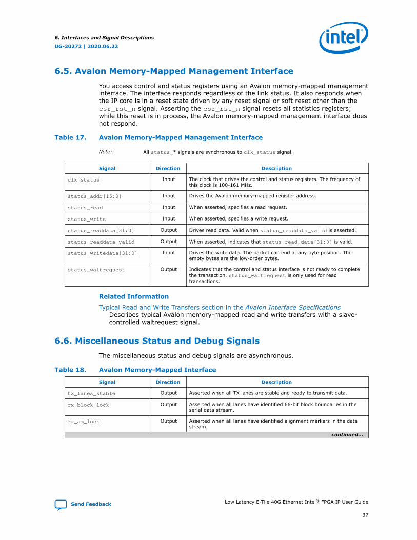
6.5. Avalon Memory-Mapped Management Interface
You access control and status registers using an Avalon memory-mapped managementinterface. The interface responds regardless of the link status. It also responds whenthe IP core is in a reset state driven by any reset signal or soft reset other than thecsr_rst_n signal. Asserting the csr_rst_n signal resets all statistics registers;while this reset is in process, the Avalon memory-mapped management interface doesnot respond.
Table 17. Avalon Memory-Mapped Management Interface
Note: All status_* signals are synchronous to clk_status signal.
Signal Direction Description
clk_status Input The clock that drives the control and status registers. The frequency ofthis clock is 100-161 MHz.
status_addr[15:0] Input Drives the Avalon memory-mapped register address.
status_read Input When asserted, specifies a read request.
status_write Input When asserted, specifies a write request.
status_readdata[31:0] Output Drives read data. Valid when status_readdata_valid is asserted.
status_readdata_valid Output When asserted, indicates that status_read_data[31:0] is valid.
status_writedata[31:0] Input Drives the write data. The packet can end at any byte position. Theempty bytes are the low-order bytes.
status_waitrequest Output Indicates that the control and status interface is not ready to completethe transaction. status_waitrequest is only used for readtransactions.
Related Information
Typical Read and Write Transfers section in the Avalon Interface SpecificationsDescribes typical Avalon memory-mapped read and write transfers with a slave-controlled waitrequest signal.
6.6. Miscellaneous Status and Debug Signals
The miscellaneous status and debug signals are asynchronous.
Table 18. Avalon Memory-Mapped Interface
Signal Direction Description
tx_lanes_stable Output Asserted when all TX lanes are stable and ready to transmit data.
rx_block_lock Output Asserted when all lanes have identified 66-bit block boundaries in theserial data stream.
rx_am_lock Output Asserted when all lanes have identified alignment markers in the datastream.
continued...
6. Interfaces and Signal Descriptions
UG-20272 | 2020.06.22
Send Feedback Low Latency E-Tile 40G Ethernet Intel® FPGA IP User Guide
37

Signal Direction Description
rx_pcs_ready Output Asserted when the RX lanes are fully aligned and ready to receive data.
local_fault_status Output Asserted when the RX MAC detects a local fault. This signal is availableonly if you turn on Enable link fault generation in the parametereditor.
remote_fault_status Output Asserted when the RX MAC detects a remote fault. This signal isavailable only if you turn on Enable link fault generation in theparameter editor.
6.7. Reset Signals
The IP core has three external hard reset inputs. These resets are asynchronous andare internally synchronized. Assert resets for ten cycles or until you observe the effectof their specific reset. Asserting the external hard reset csr_rst_n returns controland status registers to their original values. rx_pcs_ready and tx_lanes_stableare asserted when the core has exited reset successfully.
Table 19. Reset Signals
Signal Direction Description
tx_rst_n Input Active low hard reset signal. Resets the TX interface, including the TXPCS and TX MAC. This reset leads to the deassertion of thetx_lanes_stable output signal.
rx_rst_n Input Active low hard reset signal. Resets the RX interface, including the RXPCS and RX MAC. This reset leads to the deassertion of therx_pcs_ready output signal.
csr_rst_n Input Active low hard global reset. Resets the full IP core. Resets the TX MAC,RX MAC, TX PCS, RX PCS, transceivers, and registers. This reset leadsto the deassertion of the tx_lanes_stable and rx_pcs_readyoutput signals.
Related Information
Reset on page 30
6.8. Clocks
You must set the transceiver reference clock (clk_ref) frequency to a value that theIP core supports. The Low Latency E-Tile 40G Ethernet IP core supports a clk_reffrequency of 156.25 MHz ±100 ppm. The ±100ppm value is required for any clocksource providing the transceiver reference clock.
SyncE IP core variations are IP core variations for which you turn on Enable SyncE inthe parameter editor. These variations provide the RX recovered clock as a top-leveloutput signal.
The Synchronous Ethernet standard, described in the ITU-T G.8261, G.8262, andG.8264 recommendations, requires that the TX clock be filtered to maintainsynchronization with the RX reference clock through a sequence of nodes. Theexpected usage is that user logic drives the TX PLL reference clock with a filteredversion of the RX recovered clock signal, to ensure the receive and transmit functionsremain synchronized. In this usage model, a design component outside the LowLatency E-Tile 40G Ethernet IP core performs the filtering.
6. Interfaces and Signal Descriptions
UG-20272 | 2020.06.22
Low Latency E-Tile 40G Ethernet Intel® FPGA IP User Guide Send Feedback
38

Table 20. Clock InputsDescribes the input clocks that you must provide.
Signal Name Description
clk_ref The input clock clk_ref is the reference clock for the transceiver RX CDR PLL.This clock must have a frequency of 156.25 MHz with a ±100 ppm accuracy per theIEEE 802.3ba-2010 Ethernet Standard.In addition, clk_ref must meet the jitter specification of the IEEE 802.3ba-2010Ethernet Standard.The PLL and clock generation logic use this reference clock to derive the transceiverand PCS clocks. The input clock should be a high quality signal on the appropriatededicated clock pin. Refer to the relevant device datasheet for transceiver referenceclock phase noise specifications.
clk_status Clocks the control and status interface. The clock quality and pin chosen are notcritical. clk_status is expected to be a 100–161 MHz clock.
reconfig_clk Clocks the transceiver reconfiguration interface. The clock quality and pin chosenare not critical. reconfig_clk is expected to be a 100–161 MHz clock.
Table 21. Clock OutputsDescribes the output clocks that the IP core provides. In most cases these clocks participate in internal clockingof the IP core as well.
Signal Name Description
clk_txmac The TX clock for the IP core is clk_txmac. The TX MAC clock frequency is 312.5 MHz.
clk_rxmac The RX clock for the IP core is clk_rxmac. The RX MAC clock frequency is 312.5 MHz.This clock is only reliable when rx_pcs_ready has the value of 1. The IP core generatesclk_rxmac from a recovered clock that relies on the presence of incoming RX data.
clk_rx_recover RX recovered clock. This clock is available only if you turn on Enable SyncE in the LowLatency E-Tile 40G Ethernet parameter editor.The RX recovered clock frequency is 156.25 MHz during normal operation.
6.9. Flow Control Interface
Flow Control Interface signals become available when you turn on Enable MAC FlowControl in the parameter editor.
Table 22. Flow Control Signals
Signal Name Direction Description
pause_insert_tx0[(FCQN-1):0]
Input This signal is available only if Pause or PFC flow control support issynthesized. The signal indicates to the MAC whether XON or XOFFPause or PFC flow control frame should be sent.• FCQN =1 for Pause• FCQN = 1 ~ 8 for PFCThe request for XON/XOFF flow control frame transmission can be donein either 1 or 2-bit request mode (see pause_insert_tx1)1-bit mode request model:• 0: No request• 0 to 1: Generate XOFF request• 1: Continue to generate XOFF request• 1 to 0: Generate XON request2-bit mode request model: represents the lower bit. Takes effect onlywhen the CSR of a 2-bit Flow Control Request mode selects Signal.
continued...
6. Interfaces and Signal Descriptions
UG-20272 | 2020.06.22
Send Feedback Low Latency E-Tile 40G Ethernet Intel® FPGA IP User Guide
39

Signal Name Direction Description
• 00: No request• 01: XON request• 10: XOFF request• 11: Invalid request
pause_insert_tx1[(FCQN-1):0]
Input This signal is used in conjunction with pause_insert_tx0 to form a 2-bit request for XON/XOFF flow control frame transmission, representingthe upper bit of the 2-bit control.
pause_receive_rx[(FCQN-1):0]
Output Asserted to indicate an RX pause signal match. The IP core asserts bit[n] of this signal when it receives a pause request with an addressmatch, to signal the TX MAC to throttle its transmissions from priorityqueue [n] on the Ethernet link.
6. Interfaces and Signal Descriptions
UG-20272 | 2020.06.22
Low Latency E-Tile 40G Ethernet Intel® FPGA IP User Guide Send Feedback
40
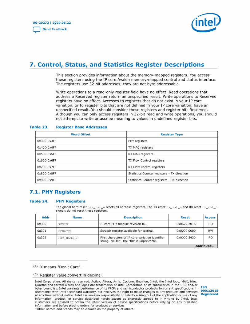
7. Control, Status, and Statistics Register DescriptionsThis section provides information about the memory-mapped registers. You accessthese registers using the IP core Avalon memory-mapped control and status interface.The registers use 32-bit addresses; they are not byte addressable.
Write operations to a read-only register field have no effect. Read operations thataddress a Reserved register return an unspecified result. Write operations to Reservedregisters have no effect. Accesses to registers that do not exist in your IP corevariation, or to register bits that are not defined in your IP core variation, have anunspecified result. You should consider these registers and register bits Reserved.Although you can only access registers in 32-bit read and write operations, you shouldnot attempt to write or ascribe meaning to values in undefined register bits.
Table 23. Register Base Addresses
Word Offset Register Type
0x300-0x3FF PHY registers
0x400-0x4FF TX MAC registers
0x500-0x5FF RX MAC registers
0x600-0x6FF TX Flow Control registers
0x700-0x7FF RX Flow Control registers
0x800-0x8FF Statistics Counter registers - TX direction
0x900-0x9FF Statistics Counter registers - RX direction
7.1. PHY Registers
Table 24. PHY RegistersThe global hard reset csr_rst_n resets all of these registers. The TX reset tx_rst_n and RX reset rx_rst_nsignals do not reset these registers.
Addr Name Description Reset Access
0x300 REVID IP core PHY module revision ID. 0x0627 2016 RO
0x301 SCRATCH Scratch register available for testing. 0x0000 0000 RW
0x302 PHY_NAME_0 First characters of IP core variation identifierstring, "0040". The "00" is unprintable.
0x0000 3430 RO
continued...
(4) X means "Don't Care".
(5) Register value convert in decimal.
UG-20272 | 2020.06.22
Send Feedback
Intel Corporation. All rights reserved. Agilex, Altera, Arria, Cyclone, Enpirion, Intel, the Intel logo, MAX, Nios,Quartus and Stratix words and logos are trademarks of Intel Corporation or its subsidiaries in the U.S. and/orother countries. Intel warrants performance of its FPGA and semiconductor products to current specifications inaccordance with Intel's standard warranty, but reserves the right to make changes to any products and servicesat any time without notice. Intel assumes no responsibility or liability arising out of the application or use of anyinformation, product, or service described herein except as expressly agreed to in writing by Intel. Intelcustomers are advised to obtain the latest version of device specifications before relying on any publishedinformation and before placing orders for products or services.*Other names and brands may be claimed as the property of others.
ISO9001:2015Registered

Addr Name Description Reset Access
0x303 PHY_NAME_1 Next characters of IP core variation identifierstring, "00GE". The "00" is unprintable.
0x0000 4745 RO
0x304 PHY_NAME_2 Final characters of IP core variation identifierstring, "0pcs". The "0" is unprintable.
0x0070 6373 RO
0x310 PHY_CONFIG PHY configuration registers. The following bitfields are defined:• Bit[0]: : sys_rst. Full system reset
(except registers). Set this bit to initiatethe internal reset sequence.
• Bit[1]: soft_txp_rst. TX soft reset.Resets TX PCS and TX MAC.
• Bit[2]: soft_rxp_rst. RX soft reset.Resets RX PCS and RX MAC.
• Bits[31:3]: Reserved.
29'hX_3'b0 (4) RW
0x312 WORD_LOCK When asserted, indicates that the virtualchannel has identified 66 bit block boundariesin the serial data stream.
28'hX4'b0 (4) RO
0x314 EIO_FLAG_SEL Supports indirect addressing of individualFIFO flags in the PCS Native PHY IP core.Program this register with the encoding for aspecific FIFO flag. The flag values (one pertransceiver) are then accessible in theEIO_FLAGS register.The value in the EIO_FLAG_SEL registerdirects the IP core to make available thefollowing FIFO flag:• 3'b000: TX FIFO full• 3'b001: TX FIFO empty• 3b010: TX FIFO partially full• 3'b011: TX FIFO partially empty• 3b100: RX FIFO full• 3b101: RX FIFO empty• 3b110: RX FIFO partially full• 3b111: RX FIFO partially empty
29'hX3'b0 (4) RW
0x315 EIO_FLAGS PCS indirect data. To read a FIFO flag, set thevalue in the EIO_FLAG_SEL register toindicate the flag you want to read. After youspecify the flag in the EIO_FLAG_SELregister, each bit [n] in the EIO_FLAGSregister has the value of that FIFO flag forthe transceiver channel for lane [n].
28'hX4'b0 (4) RO
0x321 EIO_FREQ_LOCK Each asserted bit indicates that thecorresponding lane RX clock data recovery(CDR) phase-locked loop (PLL) is locked.
28'hX4'b0 (4) RO
0x322 PHY_CLK The following encodings are defined:• Bit[0]: Indicates if the TX PCS is ready
29'hX3'b00 (4) RO
0x323 FRM_ERR Each asserted bit indicates that thecorresponding virtual lane has a frame error.You can read this register to determine if theIP core sustains a low number of frame
28'hX_4'b0 (4) RO
continued...
(4) X means "Don't Care".
(5) Register value convert in decimal.
7. Control, Status, and Statistics Register Descriptions
UG-20272 | 2020.06.22
Low Latency E-Tile 40G Ethernet Intel® FPGA IP User Guide Send Feedback
42
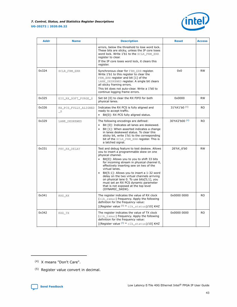
Addr Name Description Reset Access
errors, below the threshold to lose word lock.These bits are sticky, unless the IP core losesword lock. Write 1'b1 to the SCLR_FRM_ERRregister to clear.If the IP core loses word lock, it clears thisregister.
0x324 SCLR_FRM_ERR Synchronous clear for FRM_ERR register.Write 1'b1 to this register to clear theFRM_ERR register and bit [1] of theLANE_DESKEWED register. A single bit clearsall sticky framing errors.This bit does not auto-clear. Write a 1'b0 tocontinue logging frame errors.
0x0 RW
0x325 EIO_RX_SOFT_PURGE_S Set bit [0] to clear the RX FIFO for bothphysical lanes.
0x0000 RW
0x326 RX_PCS_FULLY_ALIGNED_S
Indicates the RX PCS is fully aligned andready to accept traffic.• Bit[0]: RX PCS fully aligned status.
31'hX1'b0 (4) RO
0x329 LANE_DESKEWED The following encodings are defined:• Bit [0]: Indicates all lanes are deskewed.• Bit [1]: When asserted indicates a change
in lanes deskewed status. To clear thissticky bit, write 1'b1 to the correspondingbit of the SCLR_FRM_ERR register. This isa latched signal.
30'hX2'b00 (4) RO
0x331 PHY_RX_DELAY Test and debug feature to test deskew. Allowsyou to insert a programmable skew on onephysical channel.• Bit[0]: Allows you to you to shift 33 bits
for incoming stream in physical channel 0,effectively inserting sew on two of thevirtual lanes.
• Bit[5:1]: Allows you to insert a 1-32 worddelay on the two virtual channels arrivingon physical lane 0. To use bits[5;1], youmust set an RX PCS dynamic parameterthat is not exposed at the top level(DYNAMIC_SKEW).
26'hX_6'b0 RW
0x341 KHZ_RX The register indicates the value of RX clock(clk_rxmac) frequency. Apply the followingdefinition for the frequency value:[(Register value (5) * clk_status)/10] KHZ
0x0000 0000 RO
0x342 KHZ_TX The register indicates the value of TX clock(clk_txmac) frequency. Apply the followingdefinition for the frequency value:[(Register value (5) * clk_status)/10] KHZ
0x0000 0000 RO
(4) X means "Don't Care".
(5) Register value convert in decimal.
7. Control, Status, and Statistics Register Descriptions
UG-20272 | 2020.06.22
Send Feedback Low Latency E-Tile 40G Ethernet Intel® FPGA IP User Guide
43

7.2. TX MAC Registers
Table 25. TX MAC Registers
Addr Name Description Reset Access
0x400 TXMAC_REVID TX MAC revision ID for 40GbE TX MAC CSRs. 0x0627 2016 RO
0x401 TXMAC_SCRATCH Scratch register available for testing. 0x0000 0000 RW
0x402 TXMAC_NAME_0First 4 characters of module variationidentifier string, "40gMACTxCSR". 0x3430 674D RO
0x403 TXMAC_NAME_1Next 4 characters of IP core variationidentifier string, "ACTx". 0x4143 5278 RO
0x404 TXMAC_NAME_2Final 4 characters of IP core variationidentifier string, "0CSR". The "0" isunprintable.
0x0043 5352 RO
0x405 LINK_FAULT
Link Fault Configuration Register. Thefollowing bits are defined:• Force Remote Fault bit[3]: When link
fault generation is enabled, stops datatransmission and forces transmission of aremote fault.
• Disable Remote Fault bit[2]: Whenboth link fault reporting and unidirectionaltransport are enabled, the core transmitsdata and does not transmit remote faults(RF). This bit takes effect when the valueof this register is 28'hX4'b0111.
• Unidir Enable bit[1]: When asserted,the core includes Clause 66 support forthe remote link fault reporting on theEthernet link.
• Link Fault Reporting Enablebit[0]: The following encodings aredefined:— 1'b1: The PCS generates the proper
fault sequence on Ethernet link, whenconditions are met.
— 1'b0: The PCS does not generate thefault sequence.
28'hX_4'b0001 (6) RW
0x407 MAX_TX_SIZE_CONFIG
Specifies the maximum TX frame length.Frames that are longer are consideredoversized. They are transmitted, but alsoincrement the CNTR_TX_OVERSIZE register.Bits [31:16] of this register are Reserved.
0xXXXX 2580 (6) RW
0x40A TX_MAC_CONTROL
TX MAC Control Register. A single bit isdefined:• Bit[1]: VLAN detection disabled. This bit is
deasserted by default, implying VLANdetection is enabled.
30'hX2'b0X (6) RW
(6) X means "Don't Care".
7. Control, Status, and Statistics Register Descriptions
UG-20272 | 2020.06.22
Low Latency E-Tile 40G Ethernet Intel® FPGA IP User Guide Send Feedback
44
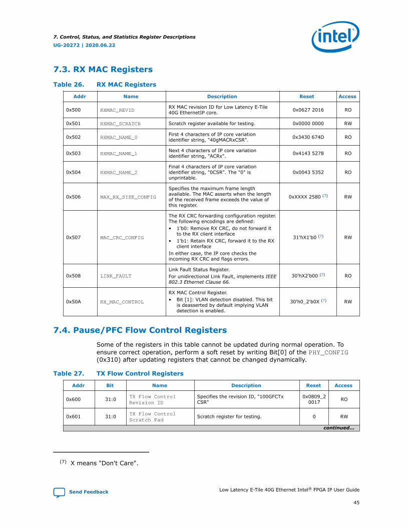
7.3. RX MAC Registers
Table 26. RX MAC Registers
Addr Name Description Reset Access
0x500 RXMAC_REVIDRX MAC revision ID for Low Latency E-Tile40G EthernetIP core. 0x0627 2016 RO
0x501 RXMAC_SCRATCH Scratch register available for testing. 0x0000 0000 RW
0x502 RXMAC_NAME_0First 4 characters of IP core variationidentifier string, "40gMACRxCSR". 0x3430 674D RO
0x503 RXMAC_NAME_1Next 4 characters of IP core variationidentifier string, "ACRx". 0x4143 5278 RO
0x504 RXMAC_NAME_2Final 4 characters of IP core variationidentifier string, "0CSR". The "0" isunprintable.
0x0043 5352 RO
0x506 MAX_RX_SIZE_CONFIG
Specifies the maximum frame lengthavailable. The MAC asserts when the lengthof the received frame exceeds the value ofthis register.
0xXXXX 2580 (7) RW
0x507 MAC_CRC_CONFIG
The RX CRC forwarding configuration register.The following encodings are defined:• 1'b0: Remove RX CRC, do not forward it
to the RX client interface• 1'b1: Retain RX CRC, forward it to the RX
client interfaceIn either case, the IP core checks theincoming RX CRC and flags errors.
31'hX1'b0 (7) RW
0x508 LINK_FAULTLink Fault Status Register.For unidirectional Link Fault, implements IEEE802.3 Ethernet Clause 66.
30'hX2'b00 (7) RO
0x50A RX_MAC_CONTROL
RX MAC Control Register.• Bit [1]: VLAN detection disabled. This bit
is deasserted by default implying VLANdetection is enabled.
30'h0_2'b0X (7) RW
7.4. Pause/PFC Flow Control Registers
Some of the registers in this table cannot be updated during normal operation. Toensure correct operation, perform a soft reset by writing Bit[0] of the PHY_CONFIG(0x310) after updating registers that cannot be changed dynamically.
Table 27. TX Flow Control Registers
Addr Bit Name Description Reset Access
0x600 31:0 TX Flow ControlRevision ID
Specifies the revision ID, "100GFCTxCSR"
0x0809_20017 RO
0x601 31:0 TX Flow ControlScratch Pad
Scratch register for testing. 0 RW
continued...
(7) X means "Don't Care".
7. Control, Status, and Statistics Register Descriptions
UG-20272 | 2020.06.22
Send Feedback Low Latency E-Tile 40G Ethernet Intel® FPGA IP User Guide
45

Addr Bit Name Description Reset Access
0x602 31:0 TX Flow Control IPCore Variant 0
Specifies first 4 characters of IP corevariation identifier ASCII string, "100G".
0x3130_3047 RO
0x603 31:0 TX Flow Control IPCore Variant 1
Next 4 characters of IP core variationidentifier ASCII string, "FCTx".
0x4643_5478 RO
0x604 31:0 TX Flow Control IPCore Variant 2
Final 4 characters of IP core variationidentifier ASCII string, "xCSR".
0x0043_5352 RO
0x6057:0
TX Flow ControlEnable
One bit per queue
Enables the IP core to generate XON andXOFF Pause/PFC flow control frames tothe remote partner. The followingencodings are defined:• 1'b0: XON or XOFF Pause/PFC flow
control is disabled.• 1'b1: XON or XOFF Pause/PFC flow
control is enabled.You can change this field dynamically.
0xFF RW
31:8 Reserved Reserved 0 RO
0x6067:0 TX Flow Control CSR
XON/XOFF Request 0
XON/XOF flow control frame request bit 0.Interpretation depends on whether the IPcore is in 1-bit FC request mode or in 2-bit FC request mode. This register affectsa flow control queue only if thecorresponding bit of the TX FlowControl Enable register has the valueof 1.In 2-bit mode, in addition, this register isactive for a specific flow control queueonly if the corresponding bit in the TX 2-bit Flow Control Request Moderegister field (bits 7:0 of the register atoffset 0x641) specifies that the flowcontrol logic accepts input from thisregister.The following encodings are defined for 1-bit mode. The IP core reads the 1-bitmode value in TX Flow Control CSRXON/XOFF Request 0.• 0 = No request• 0 to 1 = Generate XOFF request• 1 = Continue to generate XOFF
request• 1 to 0 = Generate XON requestThe following encodings are defined for 2-bit mode. The IP core reads the 2-bitmode value in {TX Flow Control CSRXON/XOFF Request 1, TX FlowControl CSR XON/XOFF Request 1}.• 00 = No request• 01 = XON request• 10 = XOFF request• 11 = InvalidYou can modify the value of this fielddynamically.
0 RW
15:8 Reserved Reserved 0 RO
continued...
7. Control, Status, and Statistics Register Descriptions
UG-20272 | 2020.06.22
Low Latency E-Tile 40G Ethernet Intel® FPGA IP User Guide Send Feedback
46
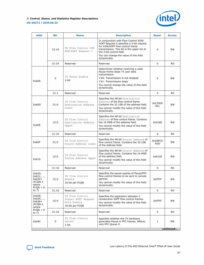
Addr Bit Name Description Reset Access
23:16 TX Flow Control CSRXON/XOFF Request 1
In conjunction with Flow Control XON/XOFF Request 0 specifies a 2-bit requestfor XON/XOFF flow control frametransmission. This bit is the upper bit ofthe 2-bit control field.You can change the value of this fielddynamically.
0 RW
31:24 Reserved Reserved 0 RO
0x60A0
TX Pause Enable
1-bit
Determines whether receiving a validPause frame stops TX user datatransmission.1'b0: Transmission is not stopped1'b1: Transmission stopsYou cannot change the value of this fielddynamically.
0 RW
31:1 Reserved Reserved 0 RO
0x60D 31:0TX Flow ControlDestination AddressLower
Specifies the 48-bit DestinationAddress of the flow control frame.Contains the 32 LSB of the address field.You cannot modify the value of this fielddynamically.
0xC2000001 RW
0x60E15:0
TX Flow ControlDestination AddressUpper
Specifies the 48-bit DestinationAddress of flow control frame. Containsthe 16 MSB of the address field.You cannot modify the value of this fielddynamically.
0x0180 RW
31:16 Reserved Reserved 0 RO
0x60F 31:0 TX Flow ControlSource Address Lower
Specifies the 48-bit Source Address offlow control frame. Contains the 32 LSBof the address field.
0xCBFC5ADD RW
0x61015:0 TX Flow Control
Source Address Upper
Specifies the 48-bit Source Address offlow control frame. Contains the 16 MSBof the address field.You cannot modify the value of this fielddynamically.
0xE100 RW
31:16 Reserved Reserved 0 RO
0x620,0x621, …,0x620+(FCQN-1whereFCQN = 0to 7)
15:0TX Flow ControlQuanta
16-bit per FCQN
Specifies the pause quanta of Pause/PFCflow control frames to be sent to remotepartner.You cannot modify the value of this fielddynamically.
0xFFFF RW
31:16 Reserved Reserved 0 RO
0x628,0x629, …,0x628+(FCQN-1whereFCQN = 0to 7)
15:0
TX Flow ControlSignal XOFF RequestHold Quanta
16-bit per FCQN
Specifies the separation between 2consecutive XOFF flow control frames.You cannot modify the value of this fielddynamically.
0xFFFF RW
31:16 Reserved Reserved 0 RO
0x640 0TX Flow ControlSelect
1-bit
Specifies whether the TX hardwaregenerates Pause or PFC frames. Affectsonly PFC Queue 0.
1 RW
continued...
7. Control, Status, and Statistics Register Descriptions
UG-20272 | 2020.06.22
Send Feedback Low Latency E-Tile 40G Ethernet Intel® FPGA IP User Guide
47
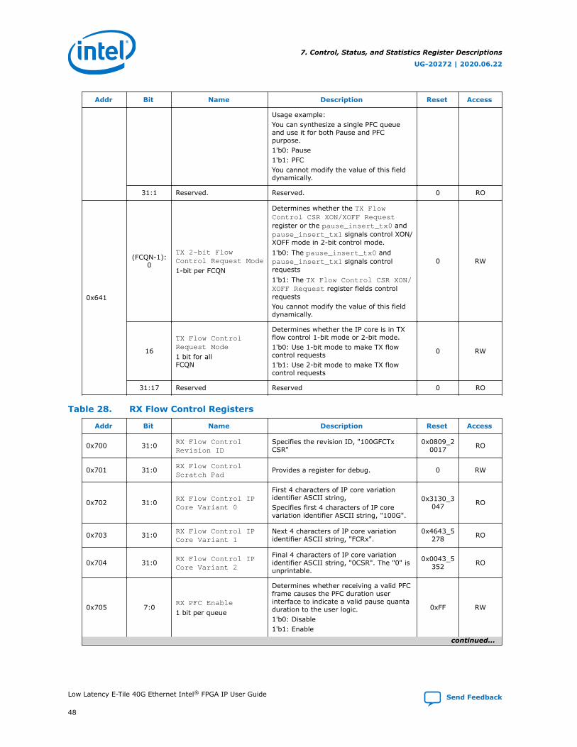
Addr Bit Name Description Reset Access
Usage example:You can synthesize a single PFC queueand use it for both Pause and PFCpurpose.1'b0: Pause1'b1: PFCYou cannot modify the value of this fielddynamically.
31:1 Reserved. Reserved. 0 RO
0x641
(FCQN-1):0
TX 2-bit FlowControl Request Mode
1-bit per FCQN
Determines whether the TX FlowControl CSR XON/XOFF Requestregister or the pause_insert_tx0 andpause_insert_tx1 signals control XON/XOFF mode in 2-bit control mode.1'b0: The pause_insert_tx0 andpause_insert_tx1 signals controlrequests1'b1: The TX Flow Control CSR XON/XOFF Request register fields controlrequestsYou cannot modify the value of this fielddynamically.
0 RW
16
TX Flow ControlRequest Mode
1 bit for allFCQN
Determines whether the IP core is in TXflow control 1-bit mode or 2-bit mode.1'b0: Use 1-bit mode to make TX flowcontrol requests1'b1: Use 2-bit mode to make TX flowcontrol requests
0 RW
31:17 Reserved Reserved 0 RO
Table 28. RX Flow Control Registers
Addr Bit Name Description Reset Access
0x700 31:0 RX Flow ControlRevision ID
Specifies the revision ID, "100GFCTxCSR"
0x0809_20017 RO
0x701 31:0 RX Flow ControlScratch Pad
Provides a register for debug. 0 RW
0x702 31:0 RX Flow Control IPCore Variant 0
First 4 characters of IP core variationidentifier ASCII string,Specifies first 4 characters of IP corevariation identifier ASCII string, "100G".
0x3130_3047 RO
0x703 31:0 RX Flow Control IPCore Variant 1
Next 4 characters of IP core variationidentifier ASCII string, "FCRx".
0x4643_5278 RO
0x704 31:0 RX Flow Control IPCore Variant 2
Final 4 characters of IP core variationidentifier ASCII string, "0CSR". The "0" isunprintable.
0x0043_5352 RO
0x705 7:0RX PFC Enable
1 bit per queue
Determines whether receiving a valid PFCframe causes the PFC duration userinterface to indicate a valid pause quantaduration to the user logic.1'b0: Disable1'b1: Enable
0xFF RW
continued...
7. Control, Status, and Statistics Register Descriptions
UG-20272 | 2020.06.22
Low Latency E-Tile 40G Ethernet Intel® FPGA IP User Guide Send Feedback
48
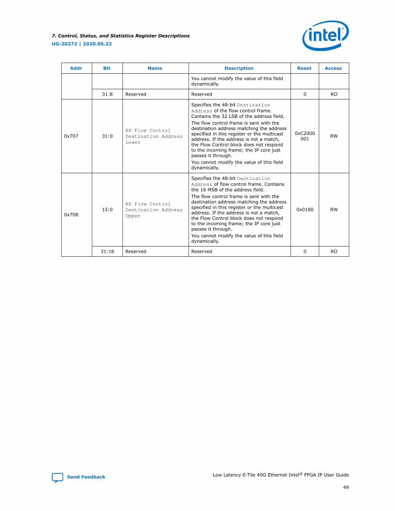
Addr Bit Name Description Reset Access
You cannot modify the value of this fielddynamically.
31:8 Reserved Reserved 0 RO
0x707 31:0RX Flow ControlDestination AddressLower
Specifies the 48-bit DestinationAddress of the flow control frame.Contains the 32 LSB of the address field.The flow control frame is sent with thedestination address matching the addressspecified in this register or the multicastaddress. If the address is not a match,the Flow Control block does not respondto the incoming frame; the IP core justpasses it through.You cannot modify the value of this fielddynamically.
0xC2000001 RW
0x70815:0
RX Flow ControlDestination AddressUpper
Specifies the 48-bit DestinationAddress of flow control frame. Containsthe 16 MSB of the address field.The flow control frame is sent with thedestination address matching the addressspecified in this register or the multicastaddress. If the address is not a match,the Flow Control block does not respondto the incoming frame; the IP core justpasses it through.You cannot modify the value of this fielddynamically.
0x0180 RW
31:16 Reserved Reserved 0 RO
7. Control, Status, and Statistics Register Descriptions
UG-20272 | 2020.06.22
Send Feedback Low Latency E-Tile 40G Ethernet Intel® FPGA IP User Guide
49

8. Debugging the LinkThe following steps should help you identify and resolve common problems that occurwhen bringing up a Low Latency E-Tile 40G Ethernet core link:
1. Establish word lock—The RX lanes should be able to achieve word lock even in thepresence of extreme bit error rates. If the IP core is unable to achieve word lock,check the transceiver clocking and data rate configuration. Check for cablingerrors such as the reversal of the TX and RX lanes. Check the clock frequencymonitors (KHZ_TX, KHZ_RX PHY registers) in the Control and Status registers.
To check for word lock: Clear the FRM_ERR register by writing the value of 1followed by another write of 0 to the SCLR_FRM_ERR register at offset 0x324.Thenread the FRM_ERR register at offset 0x323. If the value is zero, the core has wordlock. If non-zero the status is indeterminate
2. When having problems with word lock, check the EIO_FREQ_LOCK register ataddress 0x321. The values in this register define the status of the recovered clock.In normal operation, all the bits should be asserted. A non-asserted (value-0) ortoggling logic value on the bit that corresponds to any lane, indicates a clockrecovery problem. Clock recovery difficulties are typically caused by the followingproblems:
• Bit errors
• Failure to establish the link
• Incorrect clock inputs to the IP core
3. Check the PMA FIFO levels by selecting appropriate bits in the EIO_FLAG_SELregister and reading the values in the EIO_FLAGS register. During normaloperation, the TX and RX FIFOs should be nominally filled. Observing a the TXFIFO is either empty or full typically indicates a problem with clock frequencies.The RX FIFO should never be full, although an empty RX FIFO can be tolerated.
4. Establish lane integrity—When operating properly, the lanes should not experiencebit errors at a rate greater than roughly one per hour per day. Bit errors withindata packets are identified as FCS errors. Bit errors in control information,including IDLE frames, generally cause errors in XL/CGMII decoding.
5. Verify packet traffic—The Ethernet protocol includes automatic lane reordering sothe higher levels should follow the PCS. If the PCS is locked, but higher leveltraffic is corrupted, there may be a problem with the remote transmitter virtuallane tags.
6. Tuning—You can adjust transceiver analog parameters to improve the bit errorrate. IDLE traffic is representative for analog purposes.
UG-20272 | 2020.06.22
Send Feedback
Intel Corporation. All rights reserved. Agilex, Altera, Arria, Cyclone, Enpirion, Intel, the Intel logo, MAX, Nios,Quartus and Stratix words and logos are trademarks of Intel Corporation or its subsidiaries in the U.S. and/orother countries. Intel warrants performance of its FPGA and semiconductor products to current specifications inaccordance with Intel's standard warranty, but reserves the right to make changes to any products and servicesat any time without notice. Intel assumes no responsibility or liability arising out of the application or use of anyinformation, product, or service described herein except as expressly agreed to in writing by Intel. Intelcustomers are advised to obtain the latest version of device specifications before relying on any publishedinformation and before placing orders for products or services.*Other names and brands may be claimed as the property of others.
ISO9001:2015Registered
In addition, your IP core can experience loss of signal on the Ethernet link after it isestablished. In this case, the TX functionality is unaffected, but the RX functionality isdisrupted. The following symptoms indicate a loss of signal on the Ethernet link:
• The IP core deasserts the rx_pcs_ready signal, indicating the IP core has lostalignment marker lock.
• The IP core deasserts the RX PCS fully aligned status bit (bit [0]) of theRX_PCS_FULLY_ALIGNED_S register at offset 0x326. This change is linked to thechange in value of the rx_pcs_ready signal.
• If Enable link fault generation is turned on, the IP core setslocal_fault_status to the value of 1.
• The IP core triggers the RX digital reset process.
8. Debugging the Link
UG-20272 | 2020.06.22
Send Feedback Low Latency E-Tile 40G Ethernet Intel® FPGA IP User Guide
51
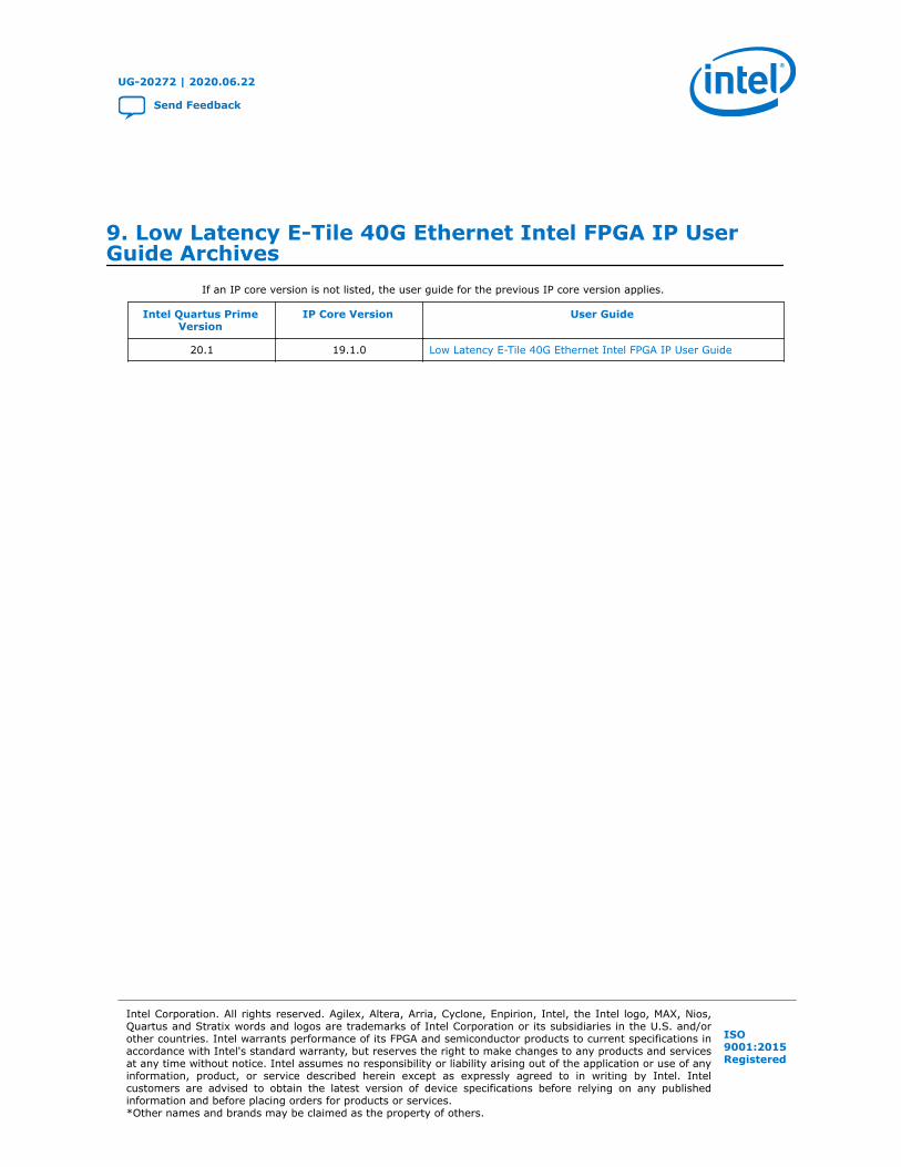
9. Low Latency E-Tile 40G Ethernet Intel FPGA IP UserGuide Archives
If an IP core version is not listed, the user guide for the previous IP core version applies.
Intel Quartus PrimeVersion
IP Core Version User Guide
20.1 19.1.0 Low Latency E-Tile 40G Ethernet Intel FPGA IP User Guide
UG-20272 | 2020.06.22
Send Feedback
Intel Corporation. All rights reserved. Agilex, Altera, Arria, Cyclone, Enpirion, Intel, the Intel logo, MAX, Nios,Quartus and Stratix words and logos are trademarks of Intel Corporation or its subsidiaries in the U.S. and/orother countries. Intel warrants performance of its FPGA and semiconductor products to current specifications inaccordance with Intel's standard warranty, but reserves the right to make changes to any products and servicesat any time without notice. Intel assumes no responsibility or liability arising out of the application or use of anyinformation, product, or service described herein except as expressly agreed to in writing by Intel. Intelcustomers are advised to obtain the latest version of device specifications before relying on any publishedinformation and before placing orders for products or services.*Other names and brands may be claimed as the property of others.
ISO9001:2015Registered
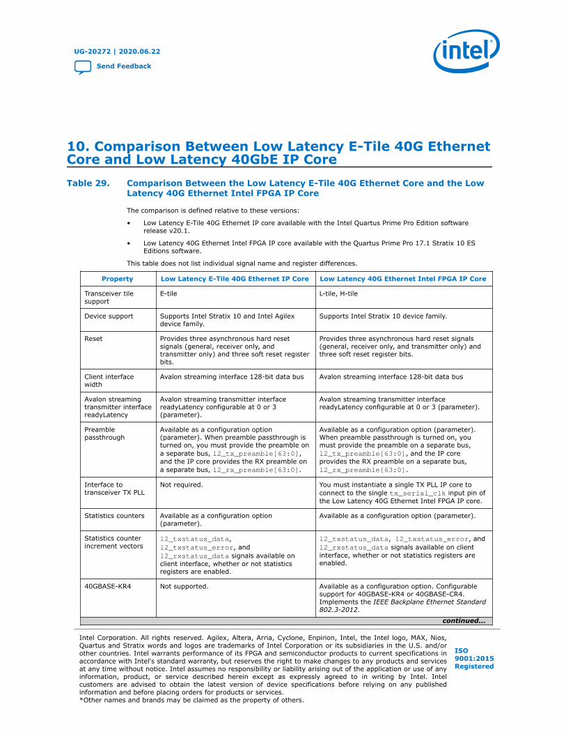
10. Comparison Between Low Latency E-Tile 40G EthernetCore and Low Latency 40GbE IP CoreTable 29. Comparison Between the Low Latency E-Tile 40G Ethernet Core and the Low
Latency 40G Ethernet Intel FPGA IP Core
The comparison is defined relative to these versions:
• Low Latency E-Tile 40G Ethernet IP core available with the Intel Quartus Prime Pro Edition softwarerelease v20.1.
• Low Latency 40G Ethernet Intel FPGA IP core available with the Quartus Prime Pro 17.1 Stratix 10 ESEditions software.
This table does not list individual signal name and register differences.
Property Low Latency E-Tile 40G Ethernet IP Core Low Latency 40G Ethernet Intel FPGA IP Core
Transceiver tilesupport
E-tile L-tile, H-tile
Device support Supports Intel Stratix 10 and Intel Agilexdevice family.
Supports Intel Stratix 10 device family.
Reset Provides three asynchronous hard resetsignals (general, receiver only, andtransmitter only) and three soft reset registerbits.
Provides three asynchronous hard reset signals(general, receiver only, and transmitter only) andthree soft reset register bits.
Client interfacewidth
Avalon streaming interface 128-bit data bus Avalon streaming interface 128-bit data bus
Avalon streamingtransmitter interfacereadyLatency
Avalon streaming transmitter interfacereadyLatency configurable at 0 or 3(parameter).
Avalon streaming transmitter interfacereadyLatency configurable at 0 or 3 (parameter).
Preamblepassthrough
Available as a configuration option(parameter). When preamble passthrough isturned on, you must provide the preamble ona separate bus, l2_tx_preamble[63:0],and the IP core provides the RX preamble ona separate bus, l2_rx_preamble[63:0].
Available as a configuration option (parameter).When preamble passthrough is turned on, youmust provide the preamble on a separate bus,l2_tx_preamble[63:0], and the IP coreprovides the RX preamble on a separate bus,l2_rx_preamble[63:0].
Interface totransceiver TX PLL
Not required. You must instantiate a single TX PLL IP core toconnect to the single tx_serial_clk input pin ofthe Low Latency 40G Ethernet Intel FPGA IP core.
Statistics counters Available as a configuration option(parameter).
Available as a configuration option (parameter).
Statistics counterincrement vectors
l2_txstatus_data,l2_txstatus_error, andl2_rxstatus_data signals available onclient interface, whether or not statisticsregisters are enabled.
l2_txstatus_data, l2_txstatus_error, andl2_rxstatus_data signals available on clientinterface, whether or not statistics registers areenabled.
40GBASE-KR4 Not supported. Available as a configuration option. Configurablesupport for 40GBASE-KR4 or 40GBASE-CR4.Implements the IEEE Backplane Ethernet Standard802.3-2012.
continued...
UG-20272 | 2020.06.22
Send Feedback
Intel Corporation. All rights reserved. Agilex, Altera, Arria, Cyclone, Enpirion, Intel, the Intel logo, MAX, Nios,Quartus and Stratix words and logos are trademarks of Intel Corporation or its subsidiaries in the U.S. and/orother countries. Intel warrants performance of its FPGA and semiconductor products to current specifications inaccordance with Intel's standard warranty, but reserves the right to make changes to any products and servicesat any time without notice. Intel assumes no responsibility or liability arising out of the application or use of anyinformation, product, or service described herein except as expressly agreed to in writing by Intel. Intelcustomers are advised to obtain the latest version of device specifications before relying on any publishedinformation and before placing orders for products or services.*Other names and brands may be claimed as the property of others.
ISO9001:2015Registered

Property Low Latency E-Tile 40G Ethernet IP Core Low Latency 40G Ethernet Intel FPGA IP Core
Flow control Available as a configuration option(parameter).
Available as a configuration option (parameter).
1588 PTP support Not supported. Not supported.
Enable alignment ofEOP on FCS word
Always turned on. Always turned on.
Minimum averageinterpacket gap
Value is 12 bytes. Value is 12 bytes.
Related Information
Low Latency 40-Gbps Ethernet IP Core User Guide
10. Comparison Between Low Latency E-Tile 40G Ethernet Core and Low Latency 40GbE IP Core
UG-20272 | 2020.06.22
Low Latency E-Tile 40G Ethernet Intel® FPGA IP User Guide Send Feedback
54
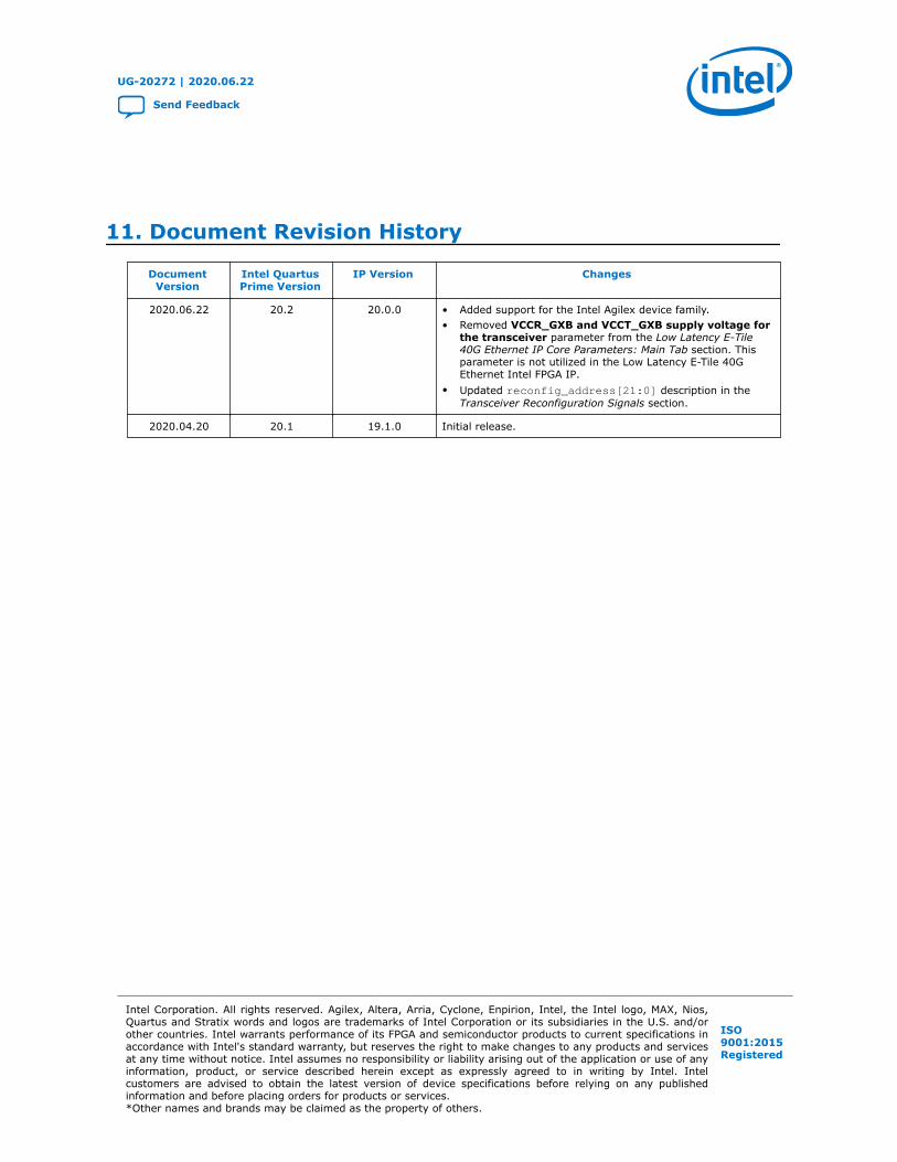
11. Document Revision History
DocumentVersion
Intel QuartusPrime Version
IP Version Changes
2020.06.22 20.2 20.0.0 • Added support for the Intel Agilex device family.• Removed VCCR_GXB and VCCT_GXB supply voltage for
the transceiver parameter from the Low Latency E-Tile40G Ethernet IP Core Parameters: Main Tab section. Thisparameter is not utilized in the Low Latency E-Tile 40GEthernet Intel FPGA IP.
• Updated reconfig_address[21:0] description in theTransceiver Reconfiguration Signals section.
2020.04.20 20.1 19.1.0 Initial release.
UG-20272 | 2020.06.22
Send Feedback
Intel Corporation. All rights reserved. Agilex, Altera, Arria, Cyclone, Enpirion, Intel, the Intel logo, MAX, Nios,Quartus and Stratix words and logos are trademarks of Intel Corporation or its subsidiaries in the U.S. and/orother countries. Intel warrants performance of its FPGA and semiconductor products to current specifications inaccordance with Intel's standard warranty, but reserves the right to make changes to any products and servicesat any time without notice. Intel assumes no responsibility or liability arising out of the application or use of anyinformation, product, or service described herein except as expressly agreed to in writing by Intel. Intelcustomers are advised to obtain the latest version of device specifications before relying on any publishedinformation and before placing orders for products or services.*Other names and brands may be claimed as the property of others.
ISO9001:2015Registered