Embed Size (px)
Citation preview
Low-Dimensional Manifolds in Direct Numerical Simulations of Autoigniting Mixing Layers Jeroen van Oijen, Ugur Göktolga, Philip de Goey 4th IWMRRF San Francisco, June 2013

MILD combustion
• Promising combustion concept • High efficiency • Low emissions • Homogeneous temperature • Low noise
• Preheated and diluted reactants • Exhaust gas recirculation • High initial T: autoignition • Low flame T: low NOx emissions
/ Mechanical Engineering PAGE 1 6/21/13
MILD
Conventional
Courtesy IFRF

Objective
Develop a numerical model for MILD combustion • Flamelet based chemical reduction (FGM) • Large eddy simulation (LES)
Multi-scale approach
• Detailed simulations of micro-scale reaction structures (10-4 m) • Reveal fundamental processes • Develop reduced chemistry model (FGM)
• Simulation of lab-scale flames (10-2 m) • Develop turbulent combustion model (LES/FGM)
• Application in industrial-scale burner systems (100 m)
/ Mechanical Engineering PAGE 2 6/21/13
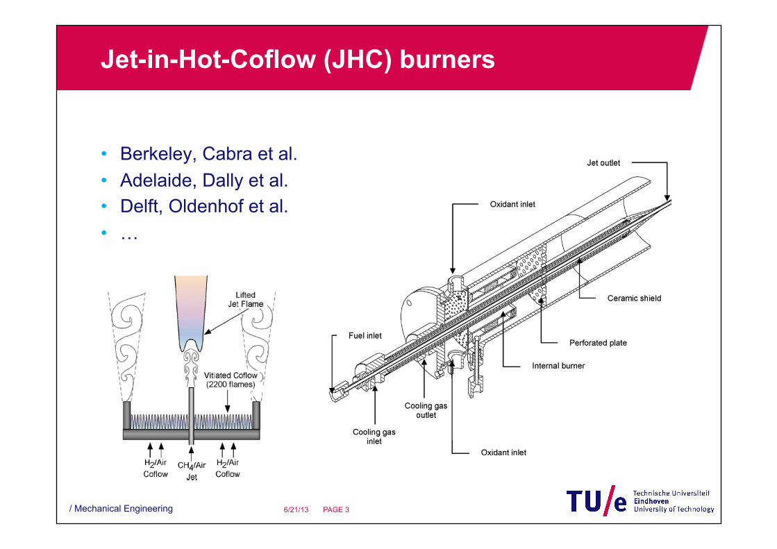
Jet-in-Hot-Coflow (JHC) burners
• Berkeley, Cabra et al. • Adelaide, Dally et al. • Delft, Oldenhof et al. • …
/ Mechanical Engineering PAGE 3 6/21/13
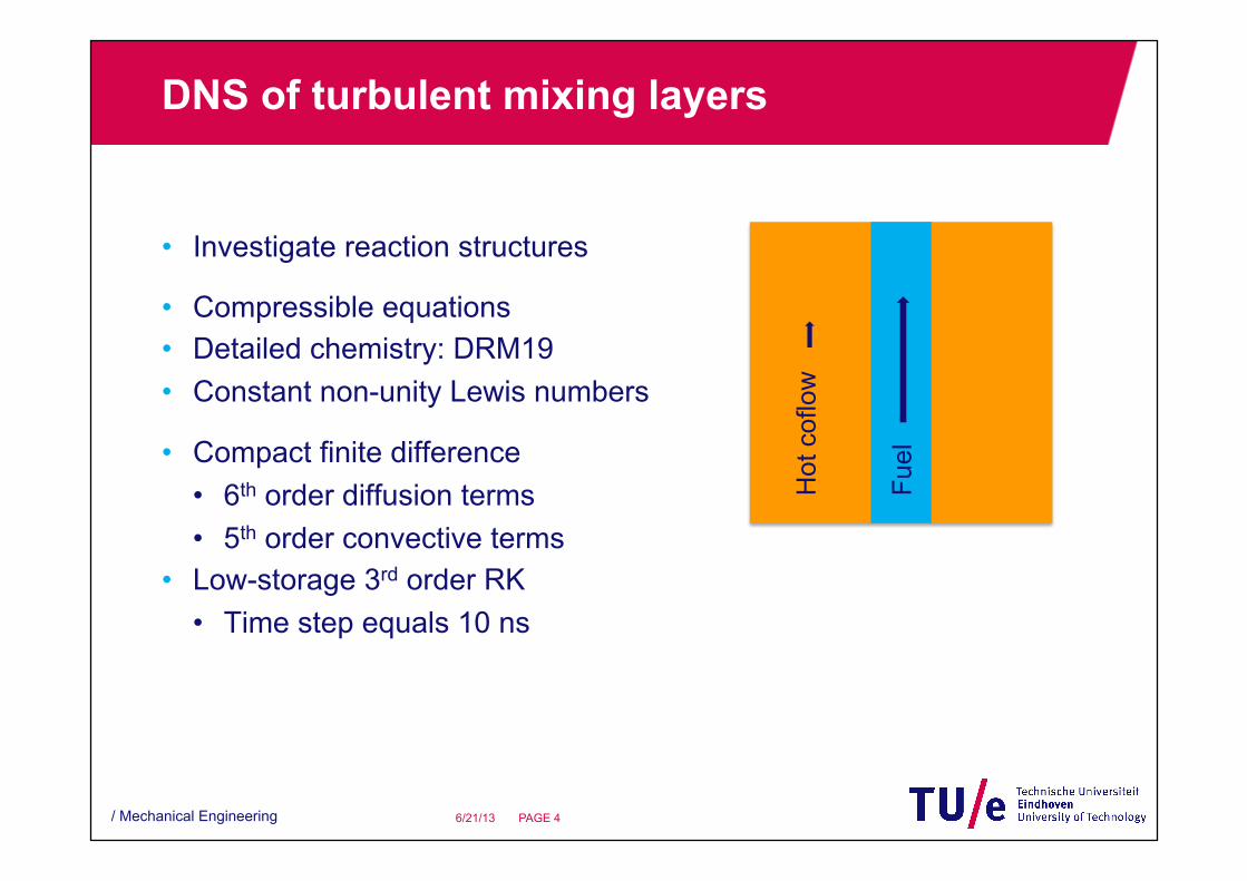
DNS of turbulent mixing layers
• Investigate reaction structures
• Compressible equations • Detailed chemistry: DRM19 • Constant non-unity Lewis numbers
• Compact finite difference • 6th order diffusion terms • 5th order convective terms
• Low-storage 3rd order RK • Time step equals 10 ns
/ Mechanical Engineering PAGE 4 6/21/13
Fuel
Hot
cof
low
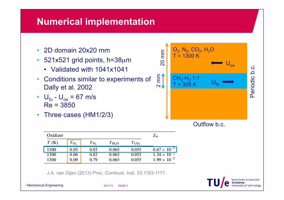
Numerical implementation
• 2D domain 20x20 mm • 521x521 grid points, h=38µm
• Validated with 1041x1041 • Conditions similar to experiments of
Dally et al. 2002 • Ufu - Uox = 67 m/s
Re = 3850 • Three cases (HM1/2/3)
/ Mechanical Engineering PAGE 5 6/21/13
CH4-H2 1:1 T = 305 K
O2, N2, CO2, H2O T = 1300 K
Per
iodi
c b.
c.
Outflow b.c.
2 m
m
20 m
m
Ufu
Uox
J.A. van Oijen (2013) Proc. Combust. Inst. 33:1163-1171

DNS results 2D mixing layer
/ Mechanical Engineering PAGE 6 6/21/13
H2 H ΔT = T – Tmix
HM1: YO2 = 0.03 Ka = τig / τη= O(10)
Green lines: Zst = 0.0067

Ignition time
• Maximum YH and temperature rise ΔT as a function of time • Comparison with laminar mixing layer and 0D homogeneous ignition
/ Mechanical Engineering PAGE 7 6/21/13
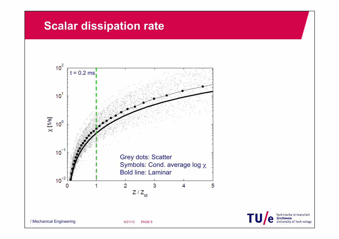
Scalar dissipation rate
/ Mechanical Engineering PAGE 8 6/21/13
Grey dots: Scatter Symbols: Cond. average log χ Bold line: Laminar
t = 0.2 ms
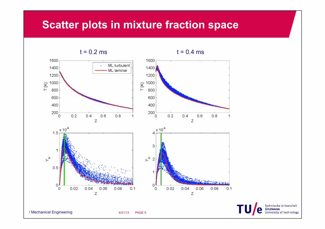
Scatter plots in mixture fraction space
/ Mechanical Engineering PAGE 9 6/21/13
t = 0.2 ms t = 0.4 ms

Scatter plot conditioned at Z = Zst
/ Mechanical Engineering PAGE 10 6/21/13
Progress variable Y is a normalized linear combination of reaction products
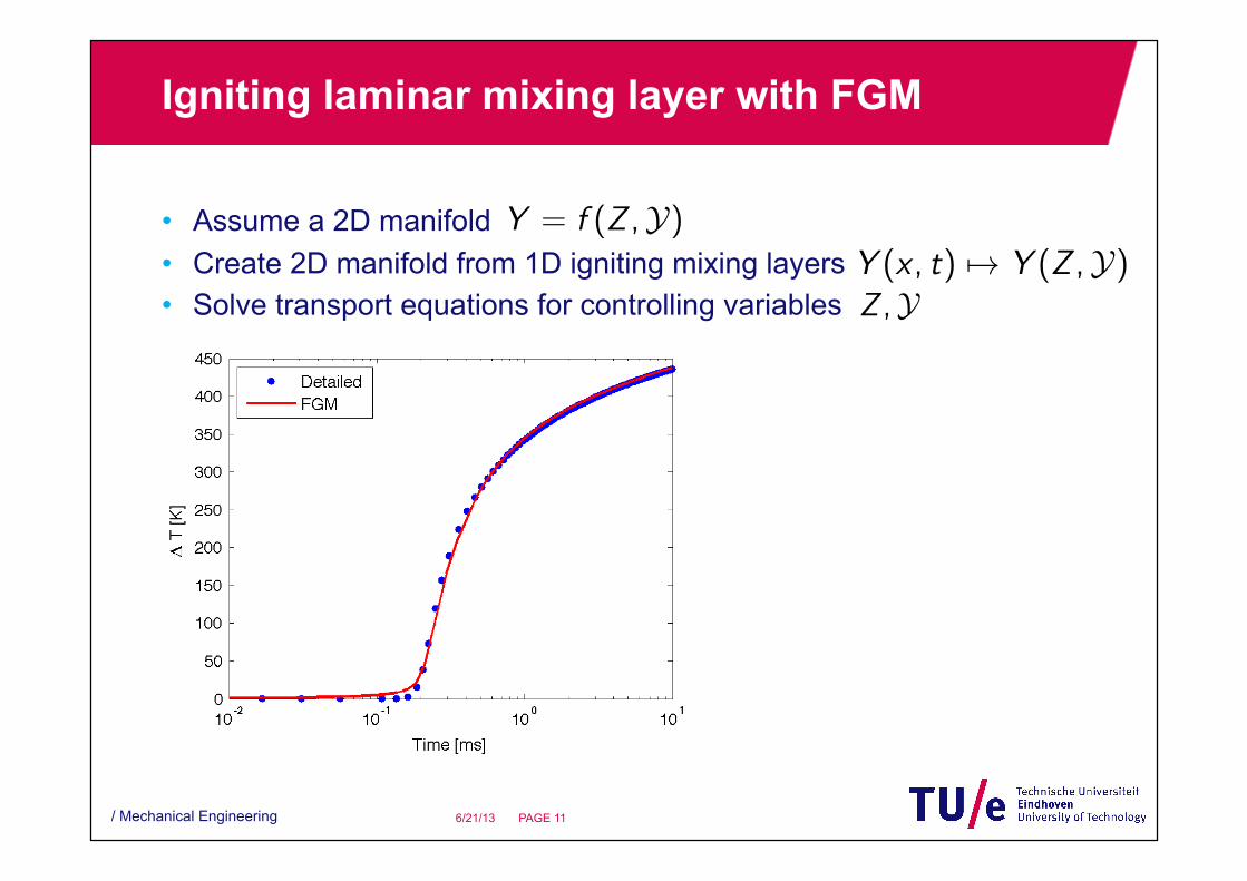
Igniting laminar mixing layer with FGM
• Assume a 2D manifold • Create 2D manifold from 1D igniting mixing layers • Solve transport equations for controlling variables
/ Mechanical Engineering PAGE 11 6/21/13
|∇Z | � |∇C|
C =Y − Yu(Z )
Yb(Z )− Yu(Z )m
m0= 1− Ka
m = ρsL
m
m0= 1− Ka +∆h
∂ lnm0
∂h+�
j
∆Zj∂ lnm0
∂Zj
m
m0= 1−MKa
∆Zj = cjKa ∆h = chKa
φ = 0.7− 12∆φ cos(2απx/Lx)
ω̇Y = �m0�Σ
�m0�1 =�
m0(Z )Pβ(Z ; �Z ,�Z ��2) dZ
�m0�2 =�
m0(Z )Pδ(Z ; �Z ) dZ = m0(�Z )
�m0�3 = m0(φ = 0.7)
�m0�Σ from DNS
�m0�Σ modeled
Y = f (Z ,Y)
Y (x , t) �→ Y (Z ,Y)
1
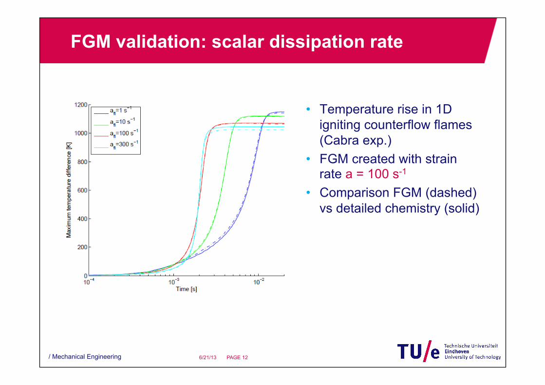
FGM validation: scalar dissipation rate
• Temperature rise in 1D igniting counterflow flames (Cabra exp.)
• FGM created with strain rate a = 100 s-1
• Comparison FGM (dashed) vs detailed chemistry (solid)
/ Mechanical Engineering PAGE 12 6/21/13
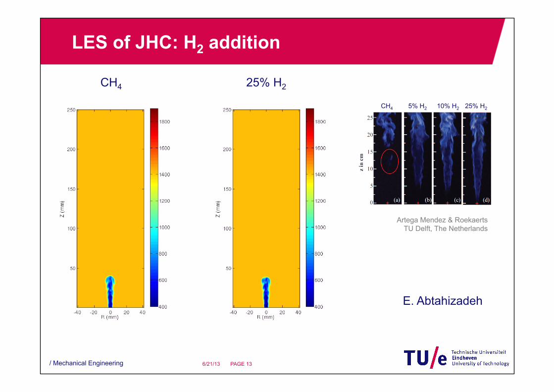
LES of JHC: H2 addition
/ Mechanical Engineering PAGE 13 6/21/13
CH4 25% H2
Artega Mendez & Roekaerts TU Delft, The Netherlands
25% H2 CH4 10% H2 5% H2
E. Abtahizadeh

Conclusions
• MILD combustion occurs in thin reaction diffusion layers • Due to the very low values of Zst, the reaction layers lie at the edge
of the turbulent mixing layer • Ignition chemistry appears to proceed along a lower-dimensional
manifold • A 2D FGM can accurately predict the ignition delay time
• Counterflow flames: various strain rates • JHC flames: capture effect of H2 addition
/ Mechanical Engineering PAGE 14 6/21/13

Outlook
• More realistic DNS • Include variations in coflow composition and temperature • Include turbulence in the coflow • 3D turbulence
• Validating FGM in DNS • Quantitative comparison of LES/FGM results with experiments • Investigate fuel effects • NOx predictions
/ Mechanical Engineering PAGE 15 6/21/13

Thank you!
• My coworkers
• Dutch Technology Foundation
/ Mechanical Engineering PAGE 16 6/21/13