Low Cost Slope Stabilisation Cost Slope Stabilisation Tim Hunt Scott Wilson (Thailand) This...
63
1 Low Cost Slope Stabilisation Tim Hunt Scott Wilson (Thailand)
Low Cost Slope Stabilisation Cost Slope Stabilisation Tim Hunt Scott Wilson (Thailand) This presentation gives an outline of the scope of work carried out under SEACAP 21. …
This presentation gives an outline of the scope of work carried out under SEACAP 21.
What do we mean by low cost?
Optimum use of low-skilled labourMaximum use of locally available materialsLogical approach to designUse of local road maintenance contractors
This will be illustrated by the work carried out under the SEACAP 21 project in Laos
2
SEACAP 21 was part of the South East Asia Community Access Programme (SEACAP) funded by the UK’s Department for International Development (DFID). The project commenced in 2006 and was completed in 2009
The Client was MPWT
The project was carried out by Scott Wilson in association with LCG and SD & XP
3
Presenter
Presentation Notes
So what is SEACAP 21 Well, it is one of the many regional SEACAP projects funded by DFID Our client is the Road Administration Division of MPWT The project has been undertaken by Scott Wilson Malaysia in association with the Lao Consulting Group.
4
SEACAP 21/001. Slope stabilisation trials on Road 13N and Road 7
SEACAP 21/002. Feasibility study for a national programmeto manage slope stability
SEACAP 21/003. Mainstreaming slope stability management into National University of Laos and MPWT
SEACAP 21/004. Training programme in landslide management
Presenter
Presentation Notes
What is the project trying to achieve? Firstly, to use best-practice appropriate methods using local materials and technologies. In other words the project is not looking at sophisticated and expensive techniques such as sheet pile retaining walls, anchoring etc, but using well-tried and tested local materials such as gabion and masonry. Secondly, to derive a better understanding of the causes of failure and how to prevent or reduce future occurrences. It includes the use of bio-engineering techniques.
5
What was the project trying to achieve?The objectives were:
To use best-practice appropriate slope stabilisationmethods using local materials and technologiesTo extend the present technologies to cover specific landslipsTo assist in the procurement and supervision of slope stabilisation trialsTo disseminate the results by means of workshops, manuals, specifications and training
SEACAP 21
Presenter
Presentation Notes
What is the project trying to achieve? Firstly, to use best-practice appropriate methods using local materials and technologies. In other words the project is not looking at sophisticated and expensive techniques such as sheet pile retaining walls, anchoring etc, but using well-tried and tested local materials such as gabion and masonry. Secondly, to derive a better understanding of the causes of failure and how to prevent or reduce future occurrences. It includes the use of bio-engineering techniques.
6
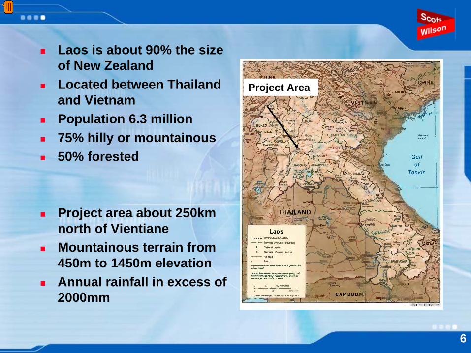
Laos is about 90% the size of New ZealandLocated between Thailand and VietnamPopulation 6.3 million75% hilly or mountainous50% forested
Project area about 250km north of VientianeMountainous terrain from 450m to 1450m elevationAnnual rainfall in excess of 2000mm
Project Area
Presenter
Presentation Notes
Where is the project located? Its centre is roughly 250km north of Vientiane on Road 13 North, the main road between Vientiane and Luang Prabang, and the connecting Road 7, which heads off eastwards to Phonsavan and the Vietnam border.
Typical below-road failure
7
Typical above-road failure
8
Typical through-road failure
Backscar
9
10
13 stabilisation sites eventually chosen comprising a mix of failure types.
Phase 1Those sites requiring mainly bio-engineering measures to
prevent further instability. This comprised 3 sites, the work carried out just prior to and during the onset of the 2007 wet season.
Phase 2 Those sites requiring mainly geotechnical measures to
prevent further instability. This comprised 10 sites, the work carried out mainly during the 2007/08 dry season.
Presenter
Presentation Notes
Using a system of ranking, 13 landslide sites were eventually chosen and subdivided into two phases: Phase 1, comprising 3 sites that could be mainly remediated using bio-engineering techniques, the work carried out at the beginning of the 2007 wet season. Phase 2, comprising 10 sites requiring mainly geotechnical engineering techniques, the work carried out during the 2007/08 dry season
11
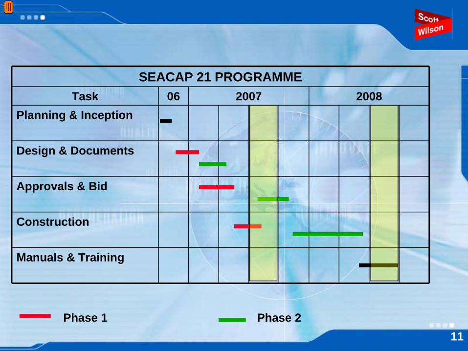
SEACAP 21 PROGRAMMETask 06 2007 2008
Planning & Inception
Design & Documents
Approvals & Bid
Construction
Manuals & Training
Phase 1 Phase 2
Presenter
Presentation Notes
This shows our project programme for the two year period October 2006 to September 2008, with Phase 1 activities shown in red and Phase 2 activities shown in green. The two main elements of the programme are: Firstly the phase 1 bio-engineering construction period carried out in the period June to August 2007, to coincide with the commencement of the wet season for plant growth Secondly the phase 2 geotechnical construction period carried out between November 2007 to July 2008 to coincide with the dry season, with additional bio-engineering work taking place immediately afterwards. We are now working on the production of technical manuals. These include a Slope Maintenance Manual, a Slope Maintenance Site Handbook and Slope Maintenance Technical Specifications.
ROAD 13N, Km 316.6: EXISTINGFAILURE
12
Presenter
Presentation Notes
Here we have a typical phase 1 site at Km 316.6 on Route 13N, comprising a shallow erosional failure above the road. The slip debris has been cleared off the road and dumped on top of the fill slope below.
ROAD 13N, Km 316.6: LANDSCAPEAPPRAISAL
Shifting cultivation on slope above failure may have
affected slope hydrology
Road benched into steep lower section of a long convex slope
Spring water emerging on slope to SE
of failure
Slope below road destabilised by large volume of debris
tipped in emergencies
Steep planar debris slide
averaging 50°
Slope composed of fragmented phyllite and residual soil,
transported and mixed to make a weak colluvial mass
13
Presenter
Presentation Notes
The initial landscape appraisal is given on this slide.
ROAD 13N, Km 316.6: PROPOSEDTREATMENT
Compactedbackfill
planted with brush layers
Trimming of head scar
3-m gabion revetment Re-instated side drain
Removeloosedebris
Dense planting with diagonal lines of grass
Tree planting around head
14
Presenter
Presentation Notes
The proposed treatment is shown on this slide, combining planting with some hard engineering at the base of the slope.
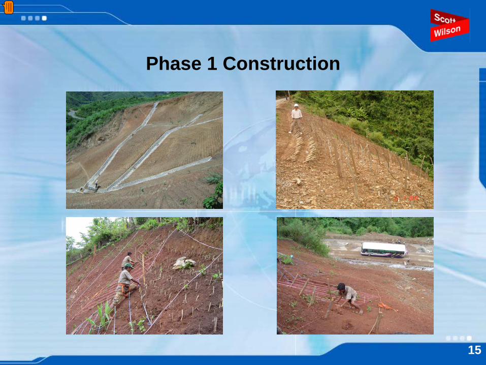
Phase 1 Construction
15
Presenter
Presentation Notes
Some typical phase 1 construction methods are illustrated here; In the top left you can see the completed masonry slope drainage prior to planting. In the top right we see two techniques for stabilising a fill slope below the road – the slope has been trimmed back to an angle of about 35 degrees and brush layers have been installed in the upper part of the slope where the man is standing, in the lower part truncheon cuttings of local tree species have been inserted to a depth of about 1 metre. In both cases the plants will root and reinforce the surface of the soil. In the bottom left the labourers are planting root and stem cuttings in diagonal lines. Over a period of about three years these will develop into large clumps of grass with deep fibrous roots. In the bottom right we can see how exposed some of these activities are above the road.
So what about construction? We have not mentioned safety before, but it needs serious consideration Here we illustrate two aspects of safety – traffic and the construction workforce. In many countries, what you see here would not be allowed. The traffic barriers would have to be able to prevent traffic from falling into the excavation, and the workers on the slope would have to wear safety harnesses. We did make some efforts on safety and we had no accidents. But perhaps we were lucky.
Removal of spoil
27
Presenter
Presentation Notes
You have dug your excavation for the wall – where are you going to dump all the excavated material? Well we all know what normally happens. It gets dumped onto the hillside below and frequently creates further instability. In SEACAP 21, the contractor was paid to remove the excavated material by truck to a predetermined safe location nearby – often a flat stable area adjacent to the road. The contractor was happy to do this – he was paid for his trouble.
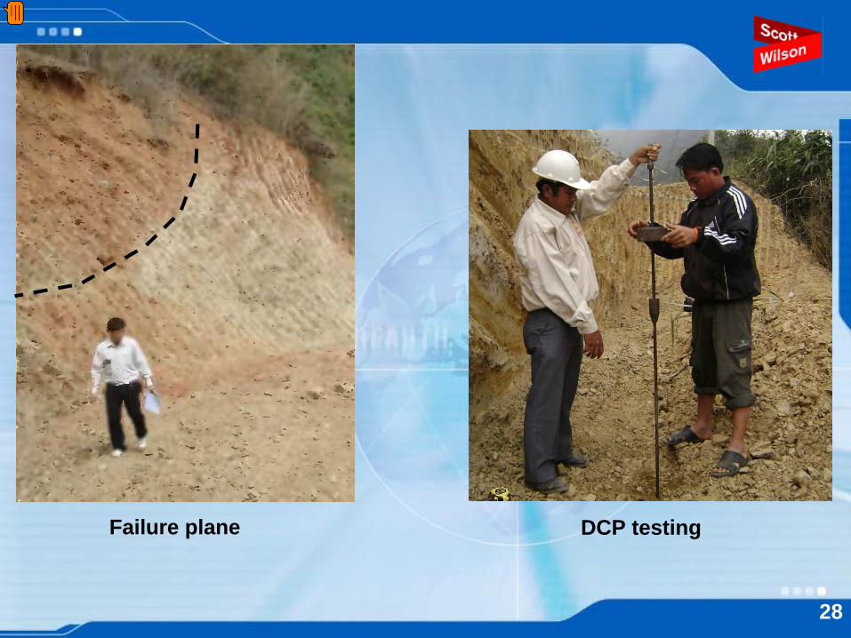
Failure plane DCP testing
28
Presenter
Presentation Notes
For retaining wall excavation one important factor to be considered is to be sure that any existing or future potential slip failure plane will not pass below the proposed wall foundation level. In the picture on the left, the failure plane daylights above the excavation and the future wall should function safely. Another factor is to be sure that the foundation will be strong enough to support the wall. Sometimes this can be done visually, sometimes not. The picture on the right shows dynamic cone penetrometer testing in progress to get an idea how strong the soil is at the proposed wall founding level.
Mortared masonry construction
29
Presenter
Presentation Notes
With mortared masonry it is important to ensure that the mortar is of the specified consistency and strength and that all the voids between the stones are filled with mortar. In the picture on the left it will be seen that there are no voids in the base of the retaining wall and that the mortar is of a reasonable consistency. However, in the picture on the right, when we get nearer the top of the wall it is apparent that the mortar is being applied far too dry and too sparingly with the result that the masonry will contain voids and the mortar will be of doubtful strength.
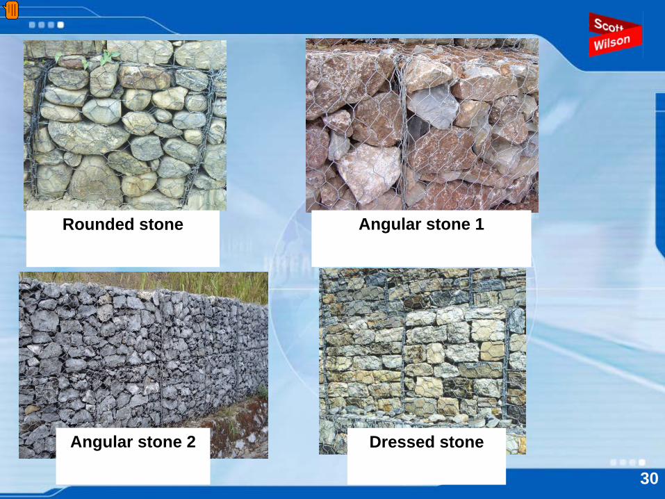
Rounded stone Angular stone 1
Dressed stoneAngular stone 2
30
Presenter
Presentation Notes
In gabion retaining wall construction we need to limit the flexibility of the gabions – otherwise the wall may bulge and become unstable. In the top left – rounded stone will allow too much flexibility and should not be used in walls unless dressed. In the top right – although angular stone has been used, there are too many voids and too much variation in stone sizes. In the bottom left – we have a good looking wall using suitably sized angular stone In the bottom right – we have top quality dressed stone with very few voids.
Backfill density testing
Compaction using pedestrian roller
31
Presenter
Presentation Notes
Compaction of backfill behind a retaining wall is very important, particularly if the road is going to be reconstructed on top of it. The picture on the left shows a sand replacement density test being carried out to ensure the correct level of compaction is being achieved. You may just see a vibrating plate compactor in the background. In the picture on the right, easier access has allowed the contractor to use a pedestrian roller.
Access track construction
Stage construction
32
Presenter
Presentation Notes
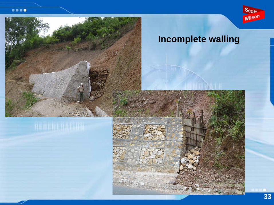
And finally two other construction considerations. The left hand picture shows the location of a proposed retaining wall and the excavated access track leading to it. However, in constructing the track we have created another area of potential instability. So think about access location very carefully before you commence. The right hand picture shows the construction of a gabion retaining wall above the road that has been partially covered by a further landslide. If you are constructing a wall in the wet season, then it is safer to excavate and build the wall in short sections to reduce the likelihood of creating further instability.
Incomplete walling
33
Estimated dimensions in contract drawings
Original ground levelShape as constructed
Retaining wall - front elevation
34
Slope Maintenance Site Handbook
Slope Maintenance Manual
35
Presenter
Presentation Notes
In this session I would like to discuss some of the issues around the maintenance of slopes beside roads. As we follow the MPWT’s definitions of maintenance, you will find that this is quite broad. As well as looking at simple routine activities, we cover a number of other much larger matters, such as wall construction as part of improvement works.
Slope Maintenance Site Handbook
36
Presenter
Presentation Notes
One of our outputs from this project is a Handbook for use by technicians on site. It is intended to provide simple and practical guidance to help the DPWTs to interpret the Maintenance Activity Codes into actions that ensure the road network is safeguarded. Most of the rest of this session follows the structure of the Handbook to show how we view the subject and aim to help the MPWT develop its capacity in this respect.
Slope Maintenance Site Handbook
Written for site staff: technicians, supervisors etcEnglish and Lao languageA5 size, 70 pages, illustrated mainly with photographsStructured around the MPWT’s MACsDefinition of Maintenance for SlopesRoutine Maintenance of SlopesEmergency Maintenance of SlopesRehabilitation and Improvement
37
Presenter
Presentation Notes
The Site Handbook is in an advanced draft stage. The MPWT is currently reviewing the technical content and the Lao translation. This shows the general attributes of the publication.
Routine Site Inspection
38
39
EmergencyMaintenance
40
Rehabilitation and Improvement
41
42
43
44
45
Slope Maintenance Manual
46
Presenter
Presentation Notes
We are also producing a more comprehensive document as an output from SEACAP 21. This is targeted at the professional engineer and intends to provide a much more in-depth account of the subject.
Slope Maintenance Manual
Written for road management professionals: engineers.English and Lao language versions.A4 size, 108 pages, illustrated with drawings & photographs.Covers all relevant aspects of site inspection, design and construction.
47
Presenter
Presentation Notes
Here are the key attributes of this document. As you can see, it is bigger and gives the user the technical and management information needed to implement slope works to quite a high standard. This is currently being circulated for comment.
Technical Specifications
Complete technical specifications for slope stabilisation and protection.English and Lao language versions.Based on international experience and best practices.Tested through SEACAP 21 trials and modified accordingly.
48
Presenter
Presentation Notes
We have also produced a set of detailed technical specifications for slope stabilisation and protection. These cover all the geotechnical and bio-engineering works that are likely to be undertaken in the Lao PDR. They have been tested through our trials in northern Laos and we have made a number of modifications to ensure that they work well. These have now been handed over to the MPWT.
InstabilityLao text...Instability
49
Diagnosis of rock slope instability
50
Instabilityin walls
51
SiteAssessment
52
Prioritisationby hazard and
risk
53
Determinationof treatment
54
Engineeringsolutions
55
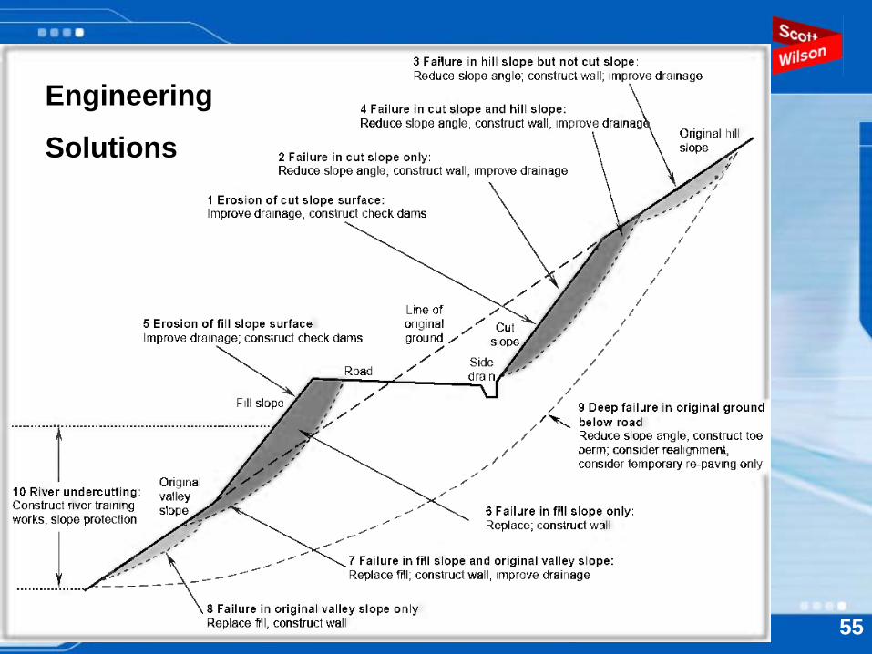
Engineering
Solutions
Engineering solutions are given for the following categories
Resolving problems of existing wallsSoil slope stabilisation with wallsDrainage improvementsRiver training and scour protectionBio-engineering techniquesRock slope stabilisation
Example: retaining wall options56
Designs are discussed for:
Wallso Composite masonryo Mortared masonryo Gabiono Other types
RevetmentsCatch wallsBio-engineering
Example: gravity wall design options25 57
58
Designingsolutions
Constructionissues
59
Typical details: Masonry Retaining Wall
60
Typical details: Grass Planting
61
Typical details: Hardwood Cutting Techniques
31 62
63
Presenter
Presentation Notes
This concludes our short consideration of maintenance. MPWT already has the right philosophy towards maintenance, and we aim just to reinforce this. We would like to add “Maintain the Slopes” to this. In the next and last of our sessions, we will give a brief overview of the lessons we have learnt from the work we have done in SEACAP 21.