Embed Size (px)
Citation preview

Automation, Control and Intelligent Systems 2018; 6(1): 1-7
http://www.sciencepublishinggroup.com/j/acis
doi: 10.11648/j.acis.20180601.11
ISSN: 2328-5583 (Print); ISSN: 2328-5591 (Online)
Low Cost Obstacle Avoidance Robot with Logic Gates and Gate Delay Calculations
Dewan Mohammed Abdul Ahad1, Dewan Mohammed Rashid
2, Md. Sajid Hossain
3, *
1Electrical & Electronic Engineering, Atish Dipankar University of Science & Technology, Dhaka, Bangladesh 2Electrical & Electronic Engineering, Ahsanullah University of Science & Technology, Dhaka, Bangladesh 3Electrical & Electronic Engineering, American International University-Bangladesh, Dhaka, Bangladesh
Email address:
*Corresponding author
To cite this article: Dewan Mohammed Abdul Ahad, Dewan Mohammed Rashid, Md. Sajid Hossain. Low Cost Obstacle Avoidance Robot with Logic Gates and
Gate Delay Calculations. Automation, Control and Intelligent Systems. Vol. 6, No. 1, 2018, pp. 1-7. doi: 10.11648/j.acis.20180601.11
Received: November 8, 2017; Accepted: January 16, 2018; Published: February 6, 2018
Abstract: As a fast growing field, robots are greatly used to achieve the desired task more accurately and mitigate the
difficulties in odd environments where human face immense difficulties. In this paper an obstacle avoidance robot has been
designed using basic gates. It can detect the obstacle and directs itself with the help of five sensors. When sensor detects an
obstacle it gives the pulse high and vice-versa. A differential drive model has been chosen, which has two wheels and a cluster
wheel. Left and right motor are used as a physical machine and it will be controlled by logic; K-map has been used to do it.
Basic gates help to execute the equation of motors as well as to make robot faster, precise and efficient. To make more
comprehensible comparative time delay estimation has been added in this paper.
Keywords: DDMR, Logic Gate, IR Sensor, K-Map, Gate Delay
1. Introduction
Robotics is a mystery. More it becomes mystery more it
relates to our life. Nowadays, indoor or outdoor wherever
people goes robot follows. Means, it assist in everywhere
where people needs. Now, to follow someone robot needs a
special kind of behaviors [1] that give it the ability to avoid
an obstacle and reach its goal [2]-[3]. Avoid obstacle robot
can be humanoid or can be mobile. This paper concentrates
on mobile obstacle avoidance robot.
The robot that moves from one spot to another is a mobile
robot [4]. In precise the robot which has the mobility (air,
land, underwater), a certain level of autonomy and perception
ability is called mobile robot [5]. To avoid an obstacle is the
primary goal for any smart mobile robot. When the robot is
going to accomplish a goal-seeking task, the whole task
divided into chunk. Obstacle avoidance is the initial one [6].
Obstacle avoidance is the fundamental concern of an
outstanding mobile robot. Collusion avoidance algorithm and
ranging sensor features helps the robot to detect the obstacle
and turn or stop at certain time [7].
Modeled obstacle avoidance robot is a differential drive
robot model with five IR sensors arranged in five sides. The
robot runs with 12 volt batteries, chassis and logic gates. The
time delay calculations of the gates have been studied which
ensure the robot’s authenticity.
2. Design Approach
Design an obstacle avoidance robot not only requires a
combination of hardware and software but also an
environmental situation. Two facts have to consider at the
time of designing a robot. The first is the world is
fundamentally unknown place. The robot does not know the
where the obstacles are, when it driving in to it’s location. So,
there are no ways to plan in advance about the robot’s
perspectives. Next, obstacles move around. A man can pass
by the robot. So, avoid-obstacles means robot would not
crush into things [1]. For that the IR sensors have been used.
Sensor will inform the robot what the world around.
Now, these sensors give the instruction to the logic gates.
Logic gates are the brain of the robot. According to their
2 Dewan Mohammed Abdul Ahad et al.: Low Cost Obstacle Avoidance Robot with Logic Gates and Gate Delay Calculations
instructions, wheels spines right or left.
Finally, a robot model has been chosen. In order to design
a robot, a robot model is needed and differential drive robot
model is the easiest and common model to study, which is
based on equation 11 and equation 12. A differential drive
robot has two wheels and a caster wheel on back [4]. When
left motor spin and right motor stop then robot moves left.
Again, when right motor spin and left motor stop then robot
move right. When both motor spin simultaneously, then robot
goes straight [8]. Every element has a coordinate. So,
designed robot needs a coordinate. In this case x, y and θ is
the position and orientation of the obstacle avoidance robot
respectively. After transition between inputs and states
following equations have been obtained [8]-[9].
θcos)(2
.
lr VVR
x += , (1)
θsin)(2
.
lr VVR
y += , (2)
)(2
.
lr VVR −=θ , (3)
These equations are the differential drive robot model
equations, where, .
x, .
y and .
θ is the process of x position, y
position of the robot change and the process of robot turning
respectively. So, this is a model in terms of mapping control
on to states, "Based on the limitations of equations (1), (2)
and (3) [9], unicycle model has been used”, which
successfully overcome the wheel velocities problem. Then,
translational velocity (v), that is speed and angular velocity
( ω ) has been considered instead of considering wheel
velocities. So, v and ω are two new input. Now, to map
them a second order unicycle dynamics is needed, they are
θcos.
vx = , (4)
θsin.
vy = , (5)
ωθ =.
, (6)
But, “Equations (4), (5) and (6) are not the differential
drive model”, v and ω of the equation (4), (5) and (6) are the
control input but Vr and Vl of equation (1) are actual control
parameters. “Both the control parameter has been mapped to
obtain the following equations [1], [8]
)(2
lr vvR
v += , (7)
lr vvR
v +=2, (8)
)( lr vvL
R −=ω , (9)
lr vvR
L −=ω, (10)
Here, equation (8) connects the translational velocity to the
real velocities. Equation (8) and (10) are linear equations”.
This has been solved to find the desired robot model.
R
Lvvr
2
2 ω+= , (11)
R
Lvvl
2
2 ω−= , (12)
So, equation (11) and equation (12) is the desired robot
model, where, L (length of the wheel base, means how far away
the wheel from each other) is wheel base and R is the radius that
says about the size of the wheel, vr is the rate of right wheel
turning and vl is the rate of left wheel turning, v and ω are
translational velocity and angular velocity respectively [1].
Figure 1 shows the differential drive robot model.
Figure 1. Differential Drive Robot Model.
Designing and implementation of an obstacle avoidance
robot is placed not only the robot model or sensor moreover
characteristics of the motors, driver IC, circuit diagram and
most importantly selection of the gates. Three basic steps
give a complete figure of the robot as step-1 was circuit
simulation, step-2 was hardware setup and step-3 was circuit
implementation. Each component has been studied in detail
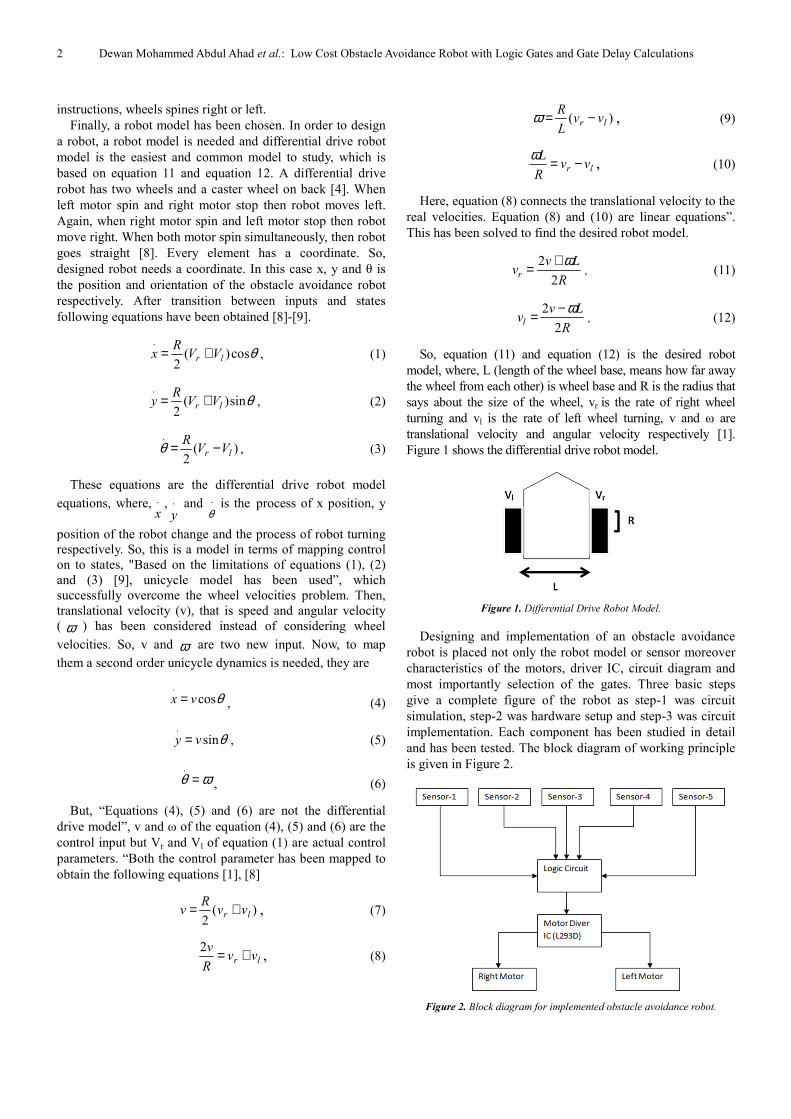
and has been tested. The block diagram of working principle
is given in Figure 2.
Figure 2. Block diagram for implemented obstacle avoidance robot.
Automation, Control and Intelligent Systems 2018; 6(1): 1-7 3
3. Carry out Equation
Digital logic only recognizes 0 and 1. When the robot
faces obstacles then IR sensors sense logic 1 or vice versa.
Based on five sensors different scenarios have been created.
Two motor has been used, named LM (left motor) and RM
(right motor). Similarly, FS (front sensor), LLS (lower left
sensor), LRS (lower right sensor), LCS (left corner sensor),
RCS (right corner sensor).
A. Scenario-1 (Move Forward) [LM=1, RM=1]
When robot does not sense any object, DDMR moves
forward. Obstacles at left side, right side and the both corner,
DDMR also moves forward. Again, when both the lower-
right and lower-left and front is clear but have obstacle in the
both left-right corner then robot moves forward. Scenario1
has been shown in Figure 3.
Figure 3. (a) All side are free from obstacle, (b) Just front side is free, (c)
lower right-left and front sides are free from obstacle.
B. Scenario-2 (Move Right) [LM=0, RM=1]
When lower right side is free and rest of the sides are full
of obstacle then the robot goes right. If the right corner side
is free and other four sensor sense obstacle robot also goes to
right direction. Figure 4 shows better illustration.
Figure 4. (a) Lower right side is free; (b) Upper right corner is free.
C. Secnario-3 (Move Left Side) [LM=1, RM=0]
Figure 5. (a) Left and front side is free from obstacle; (b) Lower left side is
free from obstacle.
When left side and front side are free but right side is full
of obstacle, robot goes to left. Again, when lower left side is
free but there are obstacles in left corner side, front side, right
side and right corner side, then robot also goes to left
direction that have been shown in Figure 5.
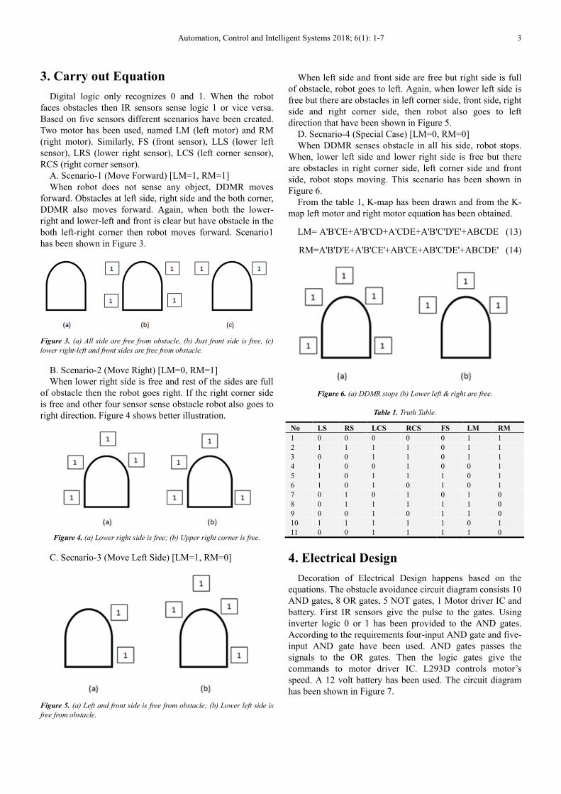
D. Secnario-4 (Special Case) [LM=0, RM=0]
When DDMR senses obstacle in all his side, robot stops.
When, lower left side and lower right side is free but there
are obstacles in right corner side, left corner side and front
side, robot stops moving. This scenario has been shown in
Figure 6.
From the table 1, K-map has been drawn and from the K-
map left motor and right motor equation has been obtained.
LM= A'B'CE+A'B'CD+A'CDE+A'B'C'D'E'+ABCDE (13)
RM=A'B'D'E+A'B'CE'+AB'CE+AB'C'DE'+ABCDE' (14)
Figure 6. (a) DDMR stops (b) Lower left & right are free.
Table 1. Truth Table.
No LS RS LCS RCS FS LM RM
1 0 0 0 0 0 1 1
2 1 1 1 1 0 1 1
3 0 0 1 1 0 1 1
4 1 0 0 1 0 0 1
5 1 0 1 1 1 0 1
6 1 0 1 0 1 0 1
7 0 1 0 1 0 1 0
8 0 1 1 1 1 1 0
9 0 0 1 0 1 1 0
10 1 1 1 1 1 0 1
11 0 0 1 1 1 1 0
4. Electrical Design
Decoration of Electrical Design happens based on the
equations. The obstacle avoidance circuit diagram consists 10
AND gates, 8 OR gates, 5 NOT gates, 1 Motor driver IC and
battery. First IR sensors give the pulse to the gates. Using
inverter logic 0 or 1 has been provided to the AND gates.
According to the requirements four-input AND gate and five-
input AND gate have been used. AND gates passes the
signals to the OR gates. Then the logic gates give the
commands to motor driver IC. L293D controls motor’s
speed. A 12 volt battery has been used. The circuit diagram
has been shown in Figure 7.

4 Dewan Mohammed Abdul Ahad et al.: Low Cost Obstacle Avoidance Robot with Logic Gates and Gate Delay Calculations
5. Mechanical Design
The implemented obstacle avoidance robot carried out its
performance well. The prototype is implemented for
educational purpose for university students. The differential
drive robot model has been made with a robust design for a
hostile environment. The hardware is not jammed
permanently; so if damage occurs it can be replaceable.
DDMR is equipped with AND gates, OR gates, Inverters,
sensors, a motor driver IC and two dc motor. A 12 volt
battery gives enough power to run all of these.
Figure 7. Circuit diagram of DDMR.
One hex inverter IC fulfills the requirement of six
inverters. At the same time 5 dual 4-input AND gate, 2
quadruple 2-input AND gate and 2 quadruple 2-input OR
gate minimize the circuit and faster the circuit operation.
These IC’s are very available and the whole design process
reducing the cost with respect to the previous version [10]. In
indoor situation obstacle avoidance robot has been tested in a
path which is approximately 100 inches long and robot
passed the test successfully that has been shown in Figure 8.
Measured value for the robot has been given in Table 2.
Figure 8. Obstacle Avoidance Robot.
Table 2. Measured Value of the Equipment’s.
Equipments Length & Width Weight Radius
Chassis & motors 9.5'' & 6'' 186 gm N/A
Upper plate 10.5'' & 6'' 82 gm N/A
Wheel N/A 80 gm 1.25''
Battery N/A 160 gm N/A
6. Results & Discussions
It has been studied that designed robot model gives more
precious direction with respect to previous version [10]. If
there are three obstacles in three sides, robot will stop. But
for the designed model there are extra sensors to detect
obstacles. Suppose left corner sensor detect an obstacle but
no obstacle in right corner sensor then robot will move right.
Because of these extra sensor robot gets a precious direction.
Figure 9 gives a better illustration.
Figure 9. Extra sensors providing precious direction.

Automation, Control and Intelligent Systems 2018; 6(1): 1-7 5
Secondly, more gates are used there is an opportunity to
fall the signal strength. That can delay the robot model. By
considering these situation gate delay has been calculated for
the both of the circuit (previous and new). That is as shown
in Figure 6, 7 and 8.
Figure 10. Gate delay of the previous circuit.
Figure 11. Gate delay of the right motor for implemented circuit.

6 Dewan Mohammed Abdul Ahad et al.: Low Cost Obstacle Avoidance Robot with Logic Gates and Gate Delay Calculations
Figure 12. Gate delay of the left motor for implemented circuit.
Figure 13. Detail gate delay calculation for implemented right motor.
Automation, Control and Intelligent Systems 2018; 6(1): 1-7 7
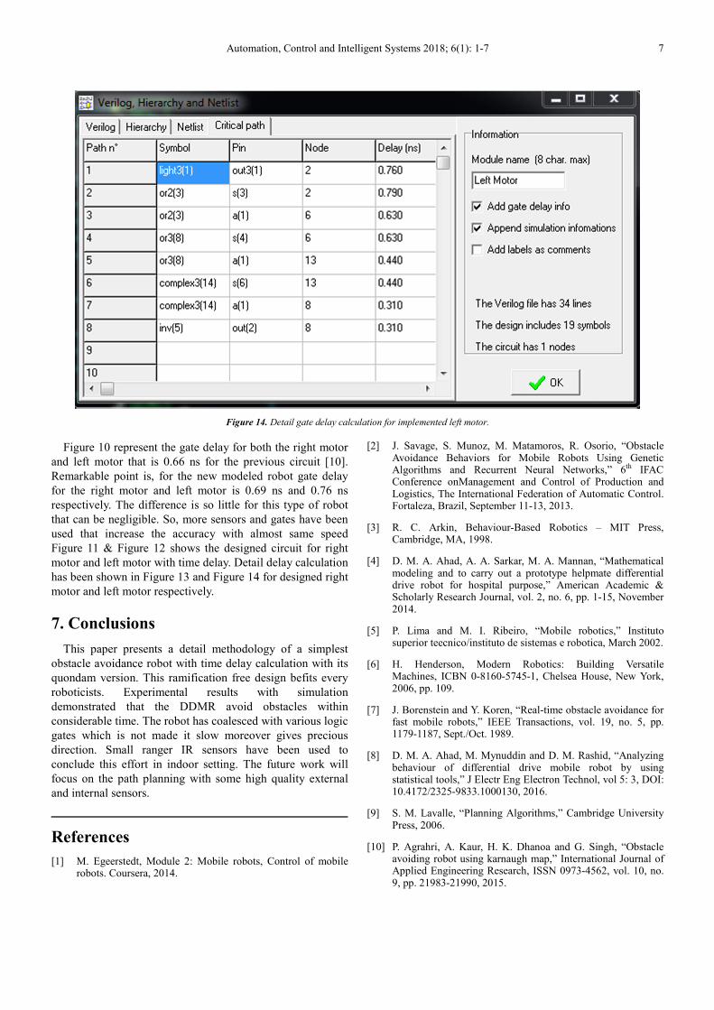
Figure 14. Detail gate delay calculation for implemented left motor.
Figure 10 represent the gate delay for both the right motor
and left motor that is 0.66 ns for the previous circuit [10].
Remarkable point is, for the new modeled robot gate delay
for the right motor and left motor is 0.69 ns and 0.76 ns
respectively. The difference is so little for this type of robot
that can be negligible. So, more sensors and gates have been
used that increase the accuracy with almost same speed
Figure 11 & Figure 12 shows the designed circuit for right
motor and left motor with time delay. Detail delay calculation
has been shown in Figure 13 and Figure 14 for designed right
motor and left motor respectively.
7. Conclusions
This paper presents a detail methodology of a simplest
obstacle avoidance robot with time delay calculation with its
quondam version. This ramification free design befits every
roboticists. Experimental results with simulation
demonstrated that the DDMR avoid obstacles within
considerable time. The robot has coalesced with various logic
gates which is not made it slow moreover gives precious
direction. Small ranger IR sensors have been used to
conclude this effort in indoor setting. The future work will
focus on the path planning with some high quality external
and internal sensors.
References
[1] M. Egeerstedt, Module 2: Mobile robots, Control of mobile robots. Coursera, 2014.
[2] J. Savage, S. Munoz, M. Matamoros, R. Osorio, “Obstacle Avoidance Behaviors for Mobile Robots Using Genetic Algorithms and Recurrent Neural Networks,” 6th IFAC Conference onManagement and Control of Production and Logistics, The International Federation of Automatic Control. Fortaleza, Brazil, September 11-13, 2013.
[3] R. C. Arkin, Behaviour-Based Robotics – MIT Press, Cambridge, MA, 1998.
[4] D. M. A. Ahad, A. A. Sarkar, M. A. Mannan, “Mathematical modeling and to carry out a prototype helpmate differential drive robot for hospital purpose,” American Academic & Scholarly Research Journal, vol. 2, no. 6, pp. 1-15, November 2014.
[5] P. Lima and M. I. Ribeiro, “Mobile robotics,” Instituto superior teecnico/instituto de sistemas e robotica, March 2002.
[6] H. Henderson, Modern Robotics: Building Versatile Machines, ICBN 0-8160-5745-1, Chelsea House, New York, 2006, pp. 109.
[7] J. Borenstein and Y. Koren, “Real-time obstacle avoidance for fast mobile robots,” IEEE Transactions, vol. 19, no. 5, pp. 1179-1187, Sept./Oct. 1989.
[8] D. M. A. Ahad, M. Mynuddin and D. M. Rashid, “Analyzing behaviour of differential drive mobile robot by using statistical tools,” J Electr Eng Electron Technol, vol 5: 3, DOI: 10.4172/2325-9833.1000130, 2016.
[9] S. M. Lavalle, “Planning Algorithms,” Cambridge University Press, 2006.
[10] P. Agrahri, A. Kaur, H. K. Dhanoa and G. Singh, “Obstacle avoiding robot using karnaugh map,” International Journal of Applied Engineering Research, ISSN 0973-4562, vol. 10, no. 9, pp. 21983-21990, 2015.