Embed Size (px)
Citation preview

Order this document byAN1664/D
AN1664
MOTOROLA LTD., 1998. All trademarks are recognized.
LOW COST 3-PHASE AC MOTOR CONTROL SYSTEM BASED ON MC68HC908MR24
By
Radim VisinkaRoznov System Application LaboratoryMotorola, Czech Republic
1 INTRODUCTION
This Application Note describes the design of a 3-phase AC induction motor drive. It is based onMotorola’s MC68HC908MR24 microcontroller which is dedicated for motor control applications. Thesystem is designed as a low cost high volume motor drive system for medium power three phase ACinduction motors and is targeted for applications in both industrial and appliance fields (e.g. washingmachines, compressors, air conditioning units, pumps or simple industrial drives).
The drive runs in a speed closed loop using a speed sensor. The code can easily be modified to run thedrive in open loop if it is required by the application. Electronic impact on the cost of the global systemcan be extremely large even if high volumes are considered, therefore the cost of the drive is strictlylimited and was a driving factor of this design.
The drive to be introduced is intended as a reference platform for a 3-phase AC induction motor drive.It can be used as a good starting point for your own design of your own application according to yourspecial requirements. It can save a lot of development engineering time and speed-up the time tomarket.
This Application Note starts with trends and general requirements for a variable speed 3-phase ACdrive. The design description incorporates both hardware and software parts of the system includinghardware schematics with a bill of material, and a software listing.
2 TRENDS IN VARIABLE SPEED DRIVES
The design of very low cost variable speed 3-phase motor control drives has become a prime focuspoint for the appliance designers and semiconductor suppliers. Replacing variable speed universalmotors by maintenance-free, low noise asynchronous (induction) motors is a trend that supposes totalsystem costs being equivalent. The big push in this direction is given by several factors:
- the new IEC555-1, European Community regulations dealing with electrical noise in power distributionlines and low power consumption
- the flexibility that can be achieved in using asynchronous motors with variable frequency
- the maturity level and affordable price trend of power devices
- the system efficiency optimization that microprocessor controlled drives can provide
- the size, weight and dissipated power reduction of the motors for a given mechanical power
Fre
esc
ale
Se
mic
on
du
cto
r, I
For More Information On This Product, Go to: www.freescale.com
nc
...

AN16642
3 SYSTEM REQUIREMENTS
The introduced AC drive is designed as a low cost system that meets the following general performancerequirements:
4 SYSTEM CONCEPT
The system is designed to drive a 3-phase AC induction motor. The microcontroller runs the main controlalgorithm. According to the user interface input and feedback signals it generates 3-phase PWM outputsignals for the motor inverter.
For the drive a standard system concept is chosen (see Figure 4-1.). The system incorporates thefollowing hardware parts:
• power supply rectifier
• three-phase inverter
• feedback sensors: speed, DC-Bus voltage, DC-Bus current
• optoisolation
• microcontroller MC68HC908MR24
The drive can basically be controlled in two different ways (or Operational Modes) that can be set by aon-board jumper.
• In the Manual Operational Mode, the required speed is set by Start/Stop switch,Forward/Reverse switch, speed potentiometer.
• In the Demo Operational Mode, the required speed profile is pre-programmed andthe only control input is the push button “Start “.
Motor Characteristic:
Motor Type4 poles, three phase, star con-nected, squirrel cage AC motor
(standard industrial motor)
Speed Range: < 3000 rpm
Base Electrical Frequency: 50 Hz
Max. Electrical Power: 500 W
Max. Phase Voltage (rms): 220V(Star) / 380V (Delta)
Drive Characteristic:
Transducers: 16 poles Tachogenerator
Frequency Range < 100Hz
Line Input: 230V / 50Hz AC
Max DC Bus Voltage 400 V
Control Algorithm Speed Closed Loop Control
Optoisolation Required
Load Characteristic: Type Varying
Table 3-1 General Requirements
Fre
esc
ale
Se
mic
on
du
cto
r, I
Freescale Semiconductor, Inc.
For More Information On This Product, Go to: www.freescale.com
nc
...

AN16643
Figure 4-1. System Concept
The
control process
is following:
The state of the sensors is periodically scanned in the software timer loop, while the speed of the motoris calculated utilising the Input Capture interrupt. According to the Operational Mode setup and state ofthe control signals (Start/Stop switch, Forward/Reverse switch, speed potentiometer) the speedcommand is calculated using an acceleration/deceleration ramp. The comparison between the actualspeed command and the tacho speed generates a speed error E. The speed error is brought to thespeed PI controller that generates a new corrected motor frequency. Using a V/Hz ramp thecorresponding voltage is calculated. The PWM generation process calculates a system of three phasevoltages of required amplitude and frequency, includes dead time and finally the 3-phase PWM MotorControl signals are generated.
3-phAC M
~=
T
Current & VoltageSensing
Optoisolation SpeedSensing
Optoisolation
ADCCurrent & Voltage
Processing
SpeedCommandProcessing
PIController
V/Hz PWMGenerator
withDead Time
Isolation Barrier
SpeedProcessing
(Input Capture)
SpeedSet-up
Microcontroller
LineVoltage
230V/50Hz
V
F
Actual Speed
OC FaultProcessing
PWMOver-Current
DC-Bus Current&
DC-Bus Voltage
-
+
DC-BusRectifier Three-Phase Inverter
E
Fre
esc
ale
Se
mic
on
du
cto
r, I
Freescale Semiconductor, Inc.
For More Information On This Product, Go to: www.freescale.com
nc
...

AN16644
The DC-Bus voltage and DC-Bus current are measured during the control process. They are used forovervoltage and overcurrent protection of the drive. The overvoltage protection is performed by softwarewhile the overcurrent fault signal utilises a fault input of the microcontroller.
If any of the above mentioned fault occurs, the motor control PWM outputs are disabled in order toprotect the drive and fault state of the system is displayed.
WARNING
It is strongly recommended to use opto-isolation (optocouplers and optoisolation ampliÞers)
during the development time to avoid any damage to the development system.
5 HARDWARE DESIGN
5.1 System Outline
The motor control system is designed to drive the 3-phase AC motor in a speed closed loop. It consistsof the following blocks (see Figure 5-1. Motor Control System Configuration):
• Microcontroller Board
• High Voltage Power Stage Board with Sensor Board
• Power Supply Board & Line Filter
• 3-Phase AC Motor with Speed Transducer
Figure 5-1. Motor Control System Configuration
High VoltagePower Supply
Auxiliary VoltagePower Supply
PowerSupplyBoard
&LineFilter
MOTOR CONTROL SYSTEM
High Voltage
SensorBoard
MC68HC908MR24Microcontroller
Board
FeedbackControlSignals
T
3-ph ACM
Speed
220V AC
Speed Setup
Power StageBoard
Fre
esc
ale
Se
mic
on
du
cto
r, I
Freescale Semiconductor, Inc.
For More Information On This Product, Go to: www.freescale.com
nc
...
AN16645
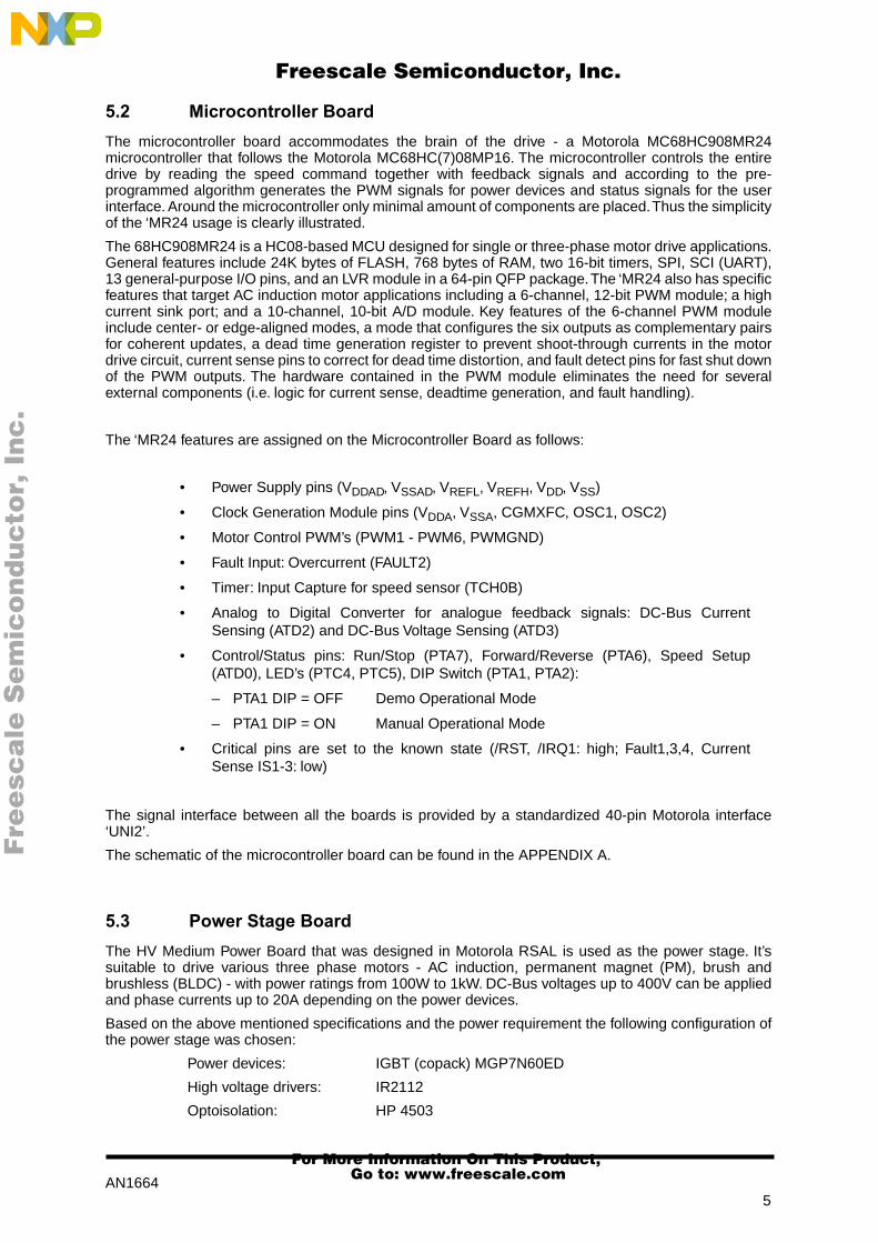
5.2 Microcontroller Board
The microcontroller board accommodates the brain of the drive - a Motorola MC68HC908MR24microcontroller that follows the Motorola MC68HC(7)08MP16. The microcontroller controls the entiredrive by reading the speed command together with feedback signals and according to the pre-programmed algorithm generates the PWM signals for power devices and status signals for the userinterface. Around the microcontroller only minimal amount of components are placed. Thus the simplicityof the ‘MR24 usage is clearly illustrated.
The 68HC908MR24 is a HC08-based MCU designed for single or three-phase motor drive applications.General features include 24K bytes of FLASH, 768 bytes of RAM, two 16-bit timers, SPI, SCI (UART),13 general-purpose I/O pins, and an LVR module in a 64-pin QFP package. The ‘MR24 also has specificfeatures that target AC induction motor applications including a 6-channel, 12-bit PWM module; a highcurrent sink port; and a 10-channel, 10-bit A/D module. Key features of the 6-channel PWM moduleinclude center- or edge-aligned modes, a mode that configures the six outputs as complementary pairsfor coherent updates, a dead time generation register to prevent shoot-through currents in the motordrive circuit, current sense pins to correct for dead time distortion, and fault detect pins for fast shut downof the PWM outputs. The hardware contained in the PWM module eliminates the need for severalexternal components (i.e. logic for current sense, deadtime generation, and fault handling).
The ‘MR24 features are assigned on the Microcontroller Board as follows:
• Power Supply pins (V
DDAD
, V
SSAD
, V
REFL
, V
REFH
, V
DD
, V
SS
)
• Clock Generation Module pins (V
DDA
, V
SSA
, CGMXFC, OSC1, OSC2)
• Motor Control PWM’s (PWM1 - PWM6, PWMGND)
• Fault Input: Overcurrent (FAULT2)
• Timer: Input Capture for speed sensor (TCH0B)
• Analog to Digital Converter for analogue feedback signals: DC-Bus CurrentSensing (ATD2) and DC-Bus Voltage Sensing (ATD3)
• Control/Status pins: Run/Stop (PTA7), Forward/Reverse (PTA6), Speed Setup(ATD0), LED’s (PTC4, PTC5), DIP Switch (PTA1, PTA2):
– PTA1 DIP = OFF Demo Operational Mode
– PTA1 DIP = ON Manual Operational Mode
• Critical pins are set to the known state (/RST, /IRQ1: high; Fault1,3,4, CurrentSense IS1-3: low)
The signal interface between all the boards is provided by a standardized 40-pin Motorola interface‘UNI2’.
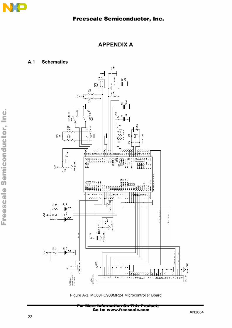
The schematic of the microcontroller board can be found in the APPENDIX A.
5.3 Power Stage Board
The HV Medium Power Board that was designed in Motorola RSAL is used as the power stage. It’ssuitable to drive various three phase motors - AC induction, permanent magnet (PM), brush andbrushless (BLDC) - with power ratings from 100W to 1kW. DC-Bus voltages up to 400V can be appliedand phase currents up to 20A depending on the power devices.
Based on the above mentioned specifications and the power requirement the following configuration ofthe power stage was chosen:
Power devices: IGBT (copack) MGP7N60ED
High voltage drivers: IR2112
Optoisolation: HP 4503
Fre
esc
ale
Se
mic
on
du
cto
r, I
Freescale Semiconductor, Inc.
For More Information On This Product, Go to: www.freescale.com
nc
...

AN16646
The schematic of the Power Stage Board can be found in the APPENDIX A.
The optoisolation galvanically isolates the power part and the control part of the system. Sixoptocouplers isolate motor control PWM signals, an additional one allows use of the fault input of theIR2112 drivers to switch off the power switches by the microcontroller when necessary. It also serves asprotection of microcontroller +5V power failure; in this case the power switches are switched offimmediately. Also all the feedback signals (voltage, current) must be isolated using the optocouplers oroptoisolation amplifiers.
Although optoisolation implies a hardware complication and added devices, including an additionalpower supply, the security of the system is highly improved. For motor control drives where cost is adriving factor of the design, the optoisolation can be omitted and the control signals of themicrocontroller can be connected directly to the high voltage drivers. Caution must be taken to avoiddamage of the system or human injury. Thus galvanic isolation of a human interface is highlyrecommended.
The detailed description of the power stage can be found in Motorola application note AN1590“HV Medium Power Board for Three Phase Motors“.
5.4 Sensor Board
The control algorithm requires speed, DC-Bus voltage and DC-Bus current sensing. Therefore thesesensors are built on the power stage board. Schematics of the sensors circuits can be found in theAPPENDIX A.
5.4.1 Speed Sensor
A 16 pole AC tachogenerator senses the actual speed of the motor. The output of the tachogenerator isan AC sinewave signal, its frequency corresponds to the motor speed. For a motor speed of 3000 rpm(100Hz synchronous) the tachogenerator output frequency is 400Hz (4 poles motor : 16 polestachogenerator). The sinusoidal signal of the tachogenerator is filtered and transformed to a logic levelsquare wave by a squaring circuit. The generated square signal is fed to the microcontroller InputCapture block of the Timer A. The Input Capture function reads the time between two subsequent risingedges of the generated square wave. The measured time corresponds to the actual speed of the motor.
Figure 5-2. Speed Sensor Block Diagram
SquaringCircuit
Speed(Input Capture)
SpeedSensor Low Pass
Filter
Fre
esc
ale
Se
mic
on
du
cto
r, I
Freescale Semiconductor, Inc.
For More Information On This Product, Go to: www.freescale.com
nc
...
AN16647
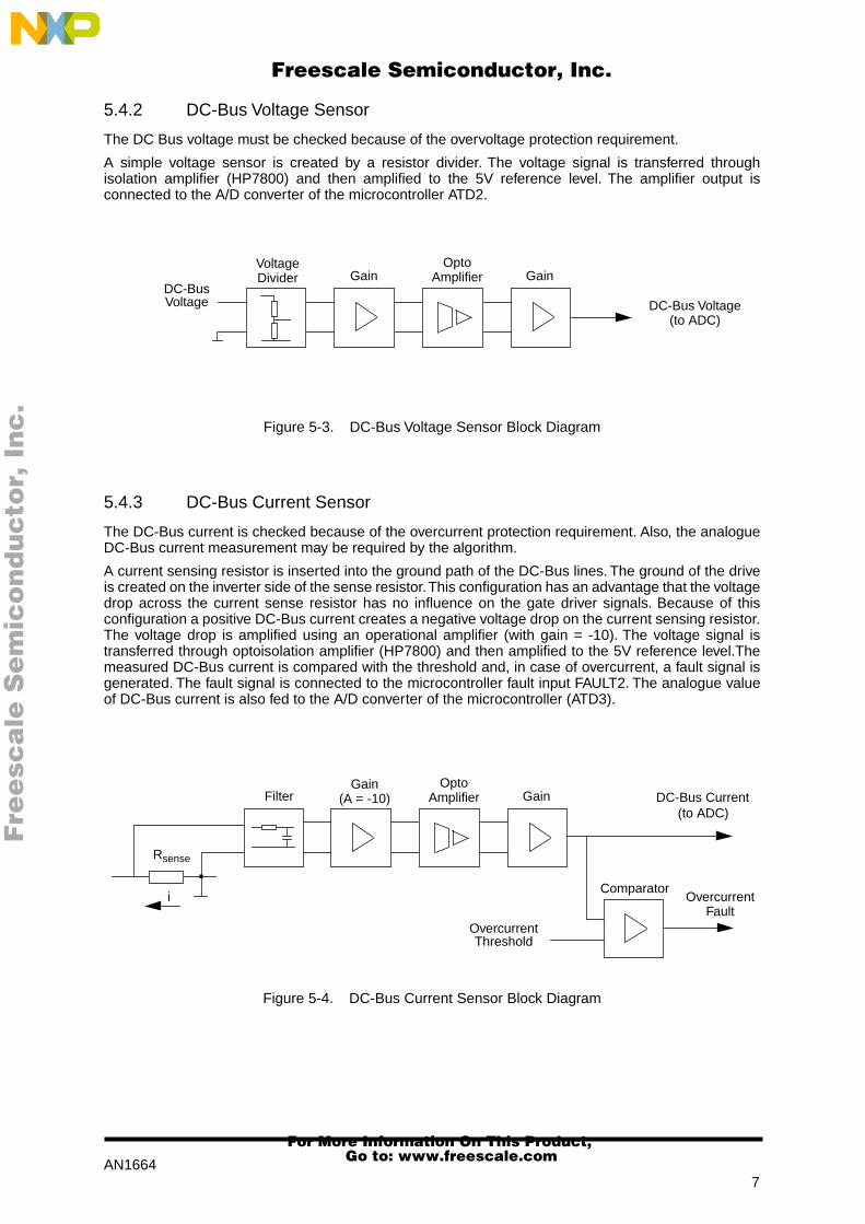
5.4.2 DC-Bus Voltage Sensor
The DC Bus voltage must be checked because of the overvoltage protection requirement.
A simple voltage sensor is created by a resistor divider. The voltage signal is transferred throughisolation amplifier (HP7800) and then amplified to the 5V reference level. The amplifier output isconnected to the A/D converter of the microcontroller ATD2.
Figure 5-3. DC-Bus Voltage Sensor Block Diagram
5.4.3 DC-Bus Current Sensor
The DC-Bus current is checked because of the overcurrent protection requirement. Also, the analogueDC-Bus current measurement may be required by the algorithm.
A current sensing resistor is inserted into the ground path of the DC-Bus lines. The ground of the driveis created on the inverter side of the sense resistor. This configuration has an advantage that the voltagedrop across the current sense resistor has no influence on the gate driver signals. Because of thisconfiguration a positive DC-Bus current creates a negative voltage drop on the current sensing resistor.The voltage drop is amplified using an operational amplifier (with gain = -10). The voltage signal istransferred through optoisolation amplifier (HP7800) and then amplified to the 5V reference level.Themeasured DC-Bus current is compared with the threshold and, in case of overcurrent, a fault signal isgenerated. The fault signal is connected to the microcontroller fault input FAULT2. The analogue valueof DC-Bus current is also fed to the A/D converter of the microcontroller (ATD3).
Figure 5-4. DC-Bus Current Sensor Block Diagram
OptoAmplifier Gain
DC-Bus Voltage(to ADC)
GainVoltageDivider
DC-BusVoltage
Rsense
i
FilterGain
(A = -10)Opto
Amplifier Gain
ComparatorOvercurrent
Fault
(to ADC)
OvercurrentThreshold
DC-Bus Current
.
Fre
esc
ale
Se
mic
on
du
cto
r, I
Freescale Semiconductor, Inc.
For More Information On This Product, Go to: www.freescale.com
nc
...

AN16648
5.5 Power Supply Board
The Power Supply Board provides a high voltage DC-Bus power supply for the drive and +5V, +15V andisolated +5V auxiliary power supply for microcontroller, optoisolation, high voltage drivers and OPamplifiers.
Typical designs of the HV DC power supply incorporate a simple one or three phase diode bridgerectifier that provides a DC-Bus voltage directly from the line. It can be followed by an inrush currentlimiter that avoids a high inrush current during switch-on operation. Also a relay can be included to switchon/off the DC-Bus voltage under microcontroller control.
Different designs for the auxiliary power supplies can be suggested. For example a classical designincludes transformer and voltage regulators. Another possibility is to use a DC-DC converter to createthe auxiliary voltage directly from the DC-Bus lines. The final configuration depends on the cost,performance and complexity comparison of both solutions.
Because the system has to meet new EMC regulations (like IEC555-1), the RF filter, harmonic distortionfilter and power factor correction have to be included. Two possibilities can be considered. Firstly a PFCdesign and secondly a choke filter. The PFC design is more complex, but the performance is higher. Thechoke filter is simple and reliable, but bulky and heavy, also the performance of the filtration is reducedcompared to the PFC.
The power supply design is a separate wide range topic described in many special articles. Therefore itis not part of this Application Note.
6 SOFTWARE DESIGN
This section describes the design of the software blocks of the drive. The software will be described interms of -
• Control Algorithm Data Flow
• State Transition
• Software Listing
• Memory Usage
• Software Modifications for Open Loop Drive
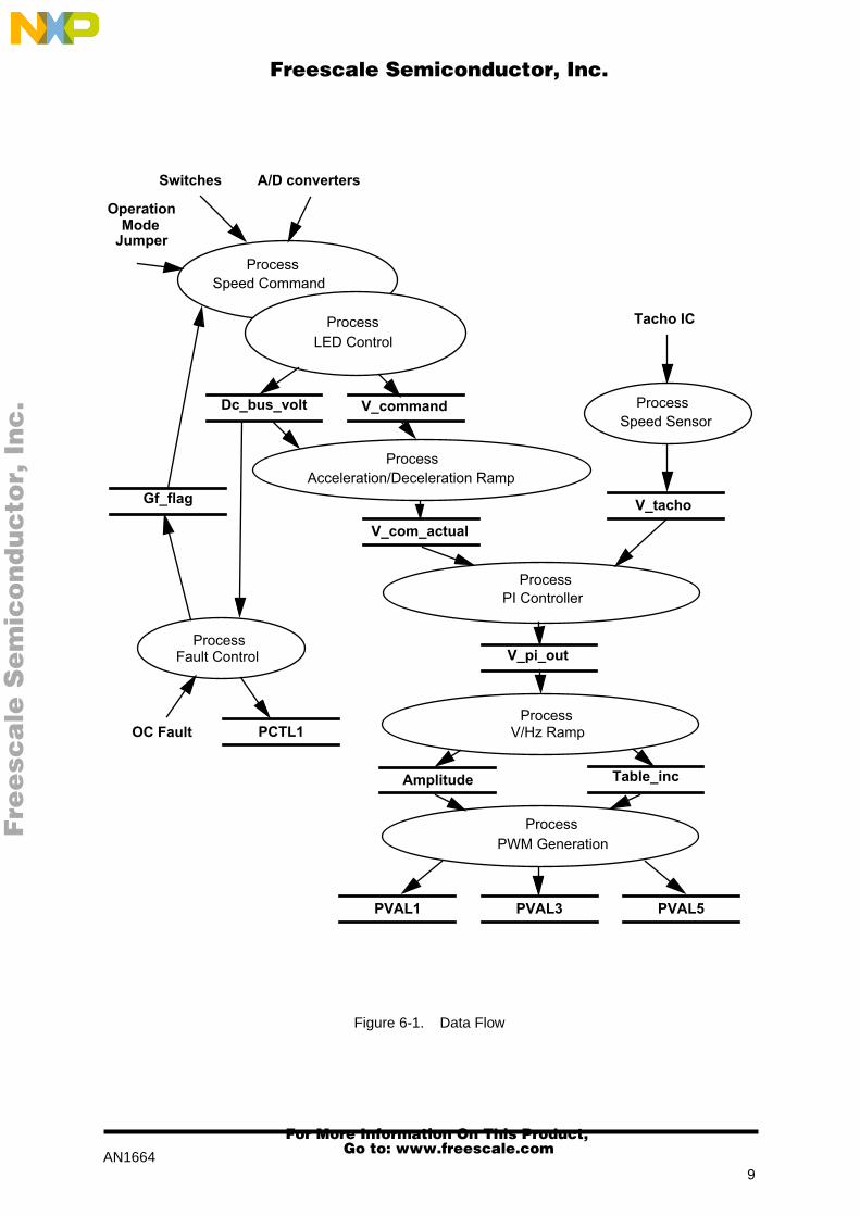
6.1 Data Flow
The requirements of the drive dictate that software takes some values from the user interface andsensors, processes them and generates 3-phase PWM signals for motor control.
The control algorithm of close loop AC drive is described in Figure 6-1. It consists of processesdescribed in following sub-sections. The special attention is given to the subroutines 3-phase PWMcalculation and Volt per Hertz control algorithm. Also initialisation of the microcontroller is described ina detail.
Fre
esc
ale
Se
mic
on
du
cto
r, I
Freescale Semiconductor, Inc.
For More Information On This Product, Go to: www.freescale.com
nc
...
AN16649
Figure 6-1. Data Flow
Switches A/D converters
Dc_bus_volt V_command
V_pi_out
Table_inc
PVAL1 PVAL5PVAL3
Amplitude
V_com_actual
V_tacho
Tacho IC
Process
Process
Process
Process
Process
Process
Process
V/Hz Ramp
PWM Generation
PI Controller
Speed Sensor
Acceleration/Deceleration Ramp
Speed Command
LED Control
OperationMode
Jumper
OC Fault
Process Fault Control
PCTL1
Gf_flag
Fre
esc
ale
Se
mic
on
du
cto
r, I
Freescale Semiconductor, Inc.
For More Information On This Product, Go to: www.freescale.com
nc
...

AN166410
6.1.1 Process Speed Command and LED Control
The process has the following input parameters:
• Operational Mode DIP: Manual OM or Demo OM
– DIP = OFF Demo Operational Mode
– DIP = ON Manual Operational Mode
• Control Switches: Start/Stop
Forward/Reverse
• A/D Converters: potentiometer output for required speed
DC-Bus Voltage sensing
• General fault flag:
Gf_flag
The process has the following output parameters:
• DC-Bus voltage
Dc_bus_volt
• Speed command
V_command
Figure 6-2. State Diagram of the Drive
Reset
Stand-By
MCS State
Fault
MCS State
PWM
MCS State
Run
MCS State
Stop
PWM disabled
disabled
PWM enabled
Over Current
Over Voltage
V_command <> 0
Start/Stop = 1
V_command =0
Start/Stop = 1
V_command = 0
Start/Stop = 0
v_pi_out = 0
V_command <> 0
General Fault = 0
PWM disabled
PWM disabled
MCS State
Fault Recovery
General Fault Recovery = 0
Fre
esc
ale
Se
mic
on
du
cto
r, I
Freescale Semiconductor, Inc.
For More Information On This Product, Go to: www.freescale.com
nc
...
AN166411
The input parameters of the process are evaluated and the speed command
V_command
is calculatedaccordingly. Also the DC-Bus voltage
Dc_bus_volt
is measured. The general fault
Gf_flag
isanalysed and the state of the drive is set. The state diagram of the drive describes Figure 6-2. The statusLED’s are controlled according the system state.
The calculated speed command
V_command
is 2-byte variable with format 8.8 (1Hz = 0x10). This formatis kept through all the program for all the speed variables.
6.1.2 Process Acceleration/Deceleration Ramp
The process calculates the new actual speed command based on the required speed according to theacceleration / deceleration ramp.
During deceleration the motor can work as a generator. In the generator state the DC-Bus capacitor ischarged and its voltage can easily exceed its maximal voltage. Therefore the DC-Bus voltage ismeasured and compared with the limit. In case of deceleration overvoltage, the deceleration isinterrupted and the motor runs with constant speed in order to discharge the capacitor. Thendeceleration can continue.
6.1.3 Process Speed Sensor
The speed sensor process utilises the IC function. It reads the time between the following rising edgesof speed sensor output and calculates the actual motor speed
V_tacho
. Also a software filter of thespeed measurement can be incorporated in the process for better noise immunity. In this case the actualmotor speed is calculated as a average value of several measurements.
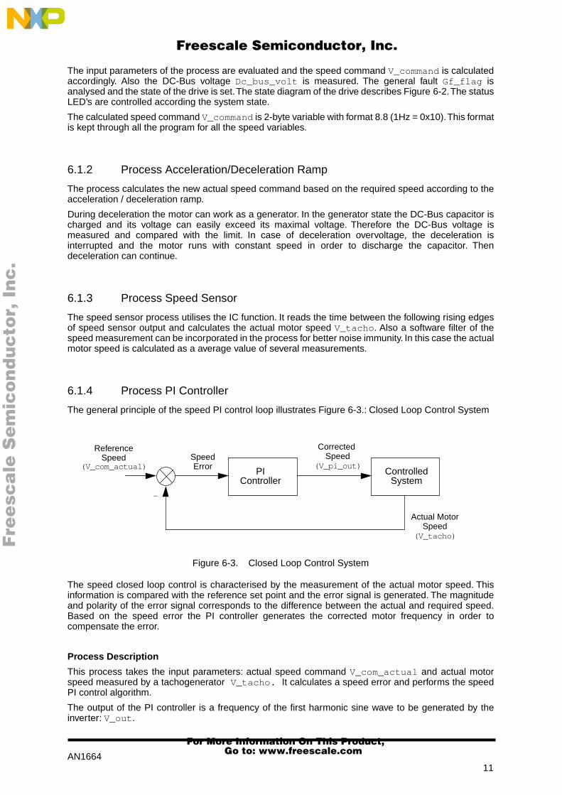
6.1.4 Process PI Controller
The general principle of the speed PI control loop illustrates Figure 6-3.: Closed Loop Control System
Figure 6-3. Closed Loop Control System
The speed closed loop control is characterised by the measurement of the actual motor speed. Thisinformation is compared with the reference set point and the error signal is generated. The magnitudeand polarity of the error signal corresponds to the difference between the actual and required speed.Based on the speed error the PI controller generates the corrected motor frequency in order tocompensate the error.
Process Description
This process takes the input parameters: actual speed command
V_com_actual
and actual motorspeed measured by a tachogenerator
V_tacho.
It calculates a speed error and performs the speedPI control algorithm.
The output of the PI controller is a frequency of the first harmonic sine wave to be generated by theinverter:
V_out
.
PIController
ControlledSystem
SpeedError
ReferenceSpeed
Corrected Speed
(V_pi_out)(V_com_actual)
Actual MotorSpeed
(V_tacho)
-
Fre
esc
ale
Se
mic
on
du
cto
r, I
Freescale Semiconductor, Inc.
For More Information On This Product, Go to: www.freescale.com
nc
...

AN166412
6.1.5 Process V/Hz Ramp
The drive is designed as a “Volt per Hertz“ drive. It means that the control algorithm keeps themagnetizing current (flux) of the motor constant by varying the stator voltage with frequency. Thecommon used Volt per Hertz ramp of a 3-phase AC induction motor illustrates Figure 6-4.
Figure 6-4. Volt per Hertz ramp
The Volt per Hertz ramp is defined by following parameters:
• Base Point - defined by Base Frequency (usually 50Hz or 60Hz)
• Boost - Defined by Boost Voltage and Boost Frequency
The ramp profile fits to the specific motor and can be easily changed to accommodate different ones.
Process Description
This process provides voltage calculation according to V/Hz ramp.
The input of this process is the generated inverter frequency
V_out
.
The output of this process are parameters required by PWM generation process:
• The table increment
Table_inc
that corresponds to the frequency
V_out
and isused to roll through the wave table in order to generate the output inverterfrequency
• Amplitude
Amplitude
of the generated inverter voltage
The example of V/Hz routine for the MC68HC908MR24 microcontroller illustrates code listing inAPPENDIX B.2: Subroutine “V/Hz Ramp”
6.1.6 Process PWM Generation
This process generates a system of three phase sinewaves (or sinewaves with addition of third harmoniccomponent) shifted 120
o
to each other.
The calculation is based on the wave table stored in ROM of the microcontroller. The table describeseither a pure sinewave or sinewave with third harmonic addition. The second case is often preferredbecause it allows one to generate a first harmonic sine voltage equal to the input AC line voltage.Because of sine symmetry only one quadrant of the wave period is stored in the table. The wave values
Frequency (rpm)
Phase
BoostVoltage
BoostFrequency
BaseFrequency
100%
BasePoint
Voltage
Fre
esc
ale
Se
mic
on
du
cto
r, I
Freescale Semiconductor, Inc.
For More Information On This Product, Go to: www.freescale.com
nc
...

AN166413
for other quadrants are calculated from the first one. The format of the stored wave table data is from
#0x00
(for ZERO Voltage) up to PWM Modulus/2 (for the 100% Voltage). Thus the proper data scalingis secured.
It is important to note that 50% PWM (or 50% of PWM Modulus loaded to the corresponding PVALregisters) corresponds to the ZERO phase voltage. But in the wave table the ZERO phase voltagecorresponds to the number
#0x00
. Therefore the fetched wave value from the table must be added tothe 50% PWM Modulation for quadrant 1 and 2 or substracted from the 50% PWM Modulation forquadrant 3 and 4 (see point 5 of the process description). Thus the correct PWM value is loaded.
The input parameters of the process are:
• The table increment
Table_inc
that is used for the wave pointer update
• Amplitude
Amplitude of the generated inverter voltage
The output parameters of the process are:
• PWM value for phase A: PVAL1 register
• PWM value for phase B: PVAL3 register
• PWM value for phase C: PVAL5 register
The process can be described by following points:
Phase A
1. Wave pointer for phase A is updated by the Table Increment
2. Based on the wave pointer of the phase the required wave quadrant is selected
3. The quadrant pointer is calculated from the wave pointer with respect to the relatedquadrant
4. Table value determined by quadrant pointer is fetched from the wave table
5. The table value is added to (or substracted from) the 50% modulus with respect tothe related quadrant
6. The result is loaded to the PVAL1 register; PVAL2 register is loaded automaticallybecause of complementary PWM mode selected during the PWM moduleinitialisation
Phase B
1. The phase B wave pointer is calculated as phase A wave pointer + 1/3 of waveperiod (1/3 of 0xffff equals to 0x5555 )
2-5. See corresponding points of the Phase A calculation
6. The result is loaded to the PVAL3 register; PVAL4 register is loaded automaticallybecause of complementary PWM mode
Phase C
1. The phase B wave pointer is calculated as phase A wave pointer + 2/3 of waveperiod (1/3 of 0xffff equals to 0xaaaa )
2-5. See corresponding points of the Phase A calculation
6. The result is loaded to the PVAL5 register; PVAL6 register is loaded automaticallybecause of complementary PWM mode
Fre
esc
ale
Se
mic
on
du
cto
r, I
Freescale Semiconductor, Inc.
For More Information On This Product, Go to: www.freescale.com
nc
...

AN166414
The process is accessed regularly in the rate given by the set PWM frequency and the selected PWMinterrupt prescaller (register PCTL2). This process has to be repeated often enough compared to thewave frequency in order to generate the correct wave shape. Therefore for 16KHz PWM frequency it iscalled each 4th PWM pulse and thus the PWM registers are updated in 4KHz rate (each 250µsec).
6.1.7 Process Fault Control
This process is responsible for fault handling. The software accommodates two fault inputs: overcurrentand overvoltage.
Overcurrent: In case of overcurrent the external hardware provides a rising edge on the fault input ofthe microcontroller FAULT2. This signal disables all Motor Control PWM’s outputs (PWM1 - PWM6) andsets general fault flag Gf_flag .
Overvoltage: The sensed DC-Bus voltage is compared with the limit within the software. In case ofovervoltage all Motor Control PWM outputs are disabled (PCTL1) and the general fault flag Gf_flag isset.
If any of the faults occur, the recovery time for the individual fault is loaded and till this time expires thesystem remains disabled.
6.2 State Diagram
The processes described above are implemented in a single state machine, as illustrated in Figure 6-5,Figure 6-6 and Figure 6-7.
The general state diagram incorporates the main routine entered from Reset and three interrupt states.The Main Routine includes the initialisation of the microcontroller and a Software Timer for the controlalgorithm time base. The interrupt states provides calculation of actual speed of the motor, overcurrentfault handler and PWM generation process.
6.2.1 Initialisation
The Main Routine provides initialisation of the microcontroller:
• clears RAM
• initialises PLL Clock
• initialises PWM module:
– center aligned complementary PWM mode, positive polarity (MOR register)
– COP and LVI enable (MOR register)
– PWM modulus - defines the PWM frequency (PMOD register)
– 2µsec dead time (DEADTM register)
– PWM interrupt reload every 4th. PWM pulse (PCTL2 register)
– FAULT2 (over current fault) in manual mode, interrupt enabled (FCR register)
• sets-up I/O ports
• initialises Timer B for IC and for software timer reference
• initialises Analog to Digital Converter
• sets-up Operational Mode (Manual OM or Demo OM)
• enables interrupts
Fre
esc
ale
Se
mic
on
du
cto
r, I
Freescale Semiconductor, Inc.
For More Information On This Product, Go to: www.freescale.com
nc
...

AN166415
Figure 6-5. State Diagram - General Overview
The example of initialisation of PLL Clock and Motor Control PWM Modules for MC68MC908MR24 isfollowing:
/* setup PLL clock */
PBWC = 0x80; /* set Auto Bandwidth Control */
while (~PBWC & 0x40); /* wait for PLL lock */
PCTL = 0x30; /* use PLL clock */
/* setup Motor Control PWM module */
MOR = 0x00; /* 0x00: pos. center PWM mode; cop and LVI enabled */
/* 0x60: neg. center PWM mode; cop and LVI enabled */
PMOD = PWM_MODULUS; /* set up PWM modulus => PWM frequency */
/* for 7.3728MHz Bus Frequency PWM_MODULUS = 0x00e6
gives 16kHz PWM */
DEADTM=15; /* 2usec deadtime = #15 (for Bus freq. = 7.3728MHz) */
DISMAP=0xff; /* when PWM disabled, disable PWM1-6 */
PCTL2 = 0x80; /* PWM interrupt every 4th. pwm loads */
InitializeSoftware
Reset
done
ICInterruptHandler
Input Capture Interrupt
done
SoftwareTimer
FaultInterruptHandler
Fault Interrupt
done
PWMInterruptHandler
PWM Interrupt
done
READ_CONST
PI_CONST
done
done
NO timeout
timeout
timeout
Fre
esc
ale
Se
mic
on
du
cto
r, I
Freescale Semiconductor, Inc.
For More Information On This Product, Go to: www.freescale.com
nc
...
AN166416
PCTL1 |= 0xc0; /* disable MCPWM */
PWMOUT = 0x00; /* output port control is PWM generator */
PCTL1 |= 0x02; /* set LDOK bit */
FCR |= 0x08; /* Flt2 enabled in manual mode */
PVAL1 = PWM_MODULUS/2; /* set phase A pwm to 50% */
PVAL3 = PWM_MODULUS/2; /* set phase B pwm to 50% */
PVAL5 = PWM_MODULUS/2; /* set phase C pwm to 50% */
When all modules of the microcontroller are initialised, enable the PWM module:
PCTL1 |= 0x20; /* enables pwm interrupts */
PCTL1 |= 0x01; /* enables PWM */
6.2.2 Software Timer
The software timer routine provides the timing sequence for required subroutines. The software timer isperformed instead of a Output Capture interrupt handler because of a lack of interrupt priority in theHC08 MCU. The main program has several time-demanding interrupt routines and more interruptrequirements can cause a software fault.
The software timer routine has two timed outputs -
• in READ_CONST timeout is a routine that scans inputs, calculates speed command,handles fault routines and the LED driver
• in PI_CONST timeout is a routine that provides overvoltage protection duringdeceleration, speed ramp (acceleration/deceleration), PI controller, V/Hz ramp andprovides parameters for PWM generation
The interrupt handlers have the following functions:
• Input Capture Interrupt Handler reads the time between the two subsequent ICedges (basic part of the Process Speed Sensor)
• Fault Interrupt Handler takes care of overcurrent fault interrupt (overcurrent part ofthe Process Fault Control)
• PWM Interrupt Handler generates system of three phase voltages for the motor(Process PWM Generation)
6.2.3 State - READ_CONST Timeout
This state is accessed from the main software timer in READ_CONST rate. The following sequence isperformed (see Figure 6-6. State - READ_CONST Timeout):
• All the inputs are scanned (DC-Bus voltage, speed pot, Start/Stop switch,Forward/Reverse switch)
• According to the operational mode the speed command is calculated
• The DC Bus voltage is compared with the overvoltage limit and overcurrent flag ischecked
• In case of fault the fault recovery routine is entered and till the recovery timeexpires, the drive stays disabled
Fre
esc
ale
Se
mic
on
du
cto
r, I
Freescale Semiconductor, Inc.
For More Information On This Product, Go to: www.freescale.com
nc
...

AN166417
• Finally the LED driver controls individual LED’s according to the status of the drive
Figure 6-6. State - READ_CONST Timeout
6.2.4 State - PI_CONST Timeout
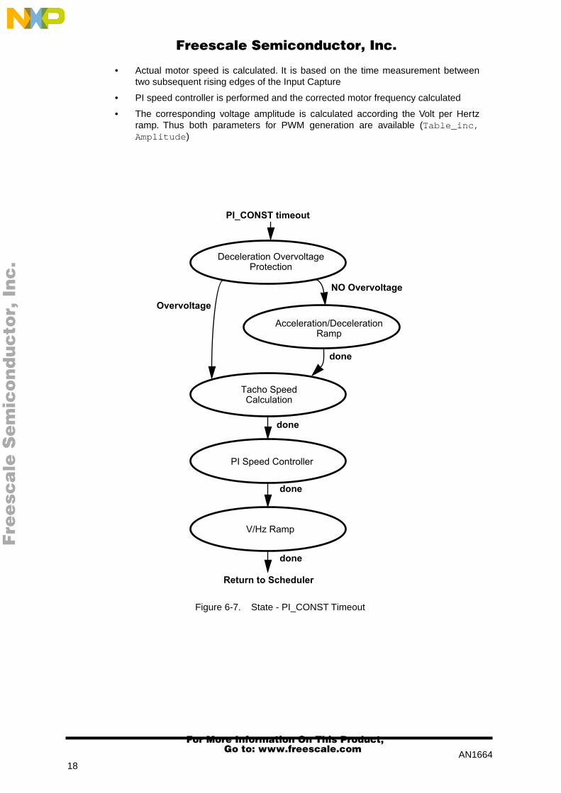
This state is accessed from the main software timer in PI_CONST rate. The rates defines the timeconstant of the PI controller. The following sequence is performed (see Figure 6-7. State - PI_CONSTTimeout):
• During deceleration the DC-Bus voltage is checked and in case of overvoltage thedeceleration is interrupted until the capacitor is discharged
• When no deceleration overvoltage is measured the acceleration/decelerationspeed profile is calculated
READ_CONST timeout
done
Scan Inputs
Fault Detection
Return to scheduler
Operational ModeDistribution
Speed CalculationDemo OM
done
donedone
LED Driver
Run Enable
Fault Recoverydone
Fault Recovery
done
Speed CalculationManual OM
done
Fre
esc
ale
Se
mic
on
du
cto
r, I
Freescale Semiconductor, Inc.
For More Information On This Product, Go to: www.freescale.com
nc
...
AN166418
• Actual motor speed is calculated. It is based on the time measurement betweentwo subsequent rising edges of the Input Capture
• PI speed controller is performed and the corrected motor frequency calculated
• The corresponding voltage amplitude is calculated according the Volt per Hertzramp. Thus both parameters for PWM generation are available (Table_inc,Amplitude )
Figure 6-7. State - PI_CONST Timeout
PI_CONST timeout
done
Deceleration OvervoltageProtection
Acceleration/DecelerationRamp
Tacho SpeedCalculation
PI Speed Controller
NO Overvoltage
Overvoltage
V/Hz Ramp
Return to Scheduler
done
done
done
Fre
esc
ale
Se
mic
on
du
cto
r, I
Freescale Semiconductor, Inc.
For More Information On This Product, Go to: www.freescale.com
nc
...

AN166419
6.3 Software Listing
The software listing is also available for this Application Note. Special attention was given to themodularity of the code. The code is written in C (C-Cross compiler - Cosmic Software Inc.).
The code listing can be found on Motorola Web page: http://Design_NET.com
The software consists of the following parts:
6.3.1 MAIN.C
It is the entry point following a Reset. It contains the Initialise Software State code, the Main statemachine with the Software Timer State code.
6.3.2 SPEED.C
Contains READ_CONST Timeout code (Scan Inputs State, OM Distribution State, Speed Calculation- Manual OM State, Speed Calculation - Demo OM State, Fault Detection State, Run Enable State, FaultRecovery State, LED Driver State).
6.3.3 RAMP.C
Contains code for ramps: Acceleration/Deceleration Ramp State, V/Hz Ramp State.
6.3.4 PI.C
Contains PI_CONST Timeout code (Deceleration Overvoltage Protection State, Tacho SpeedCalculation State, PI Speed Controller State and calls Acceleration/Deceleration Ramp State and V/HzRamp State appropriately).
6.3.5 FAULT.C
Contains Fault Interrupt Handler code.
6.3.6 PWMCALC.C
Contains PWM Calculation Interrupt Handler code.
6.3.7 TACHO.C
Contains Tacho Interrupt Handler code.
6.3.8 3RDHQUAD.H
Contains the first quadrant of sinewave with its 3rd. harmonic injection - 256 unsigned 2-byte entries.
6.3.9 RAM.H
Contains the global RAM variable definitions for the whole project.
6.3.10 CONST.H
Contains the global constants definitions for the whole project.
6.3.11 VECTORS.H
Contains the interrupt vectors.
Fre
esc
ale
Se
mic
on
du
cto
r, I
Freescale Semiconductor, Inc.
For More Information On This Product, Go to: www.freescale.com
nc
...
AN166420
7 OPEN LOOP DRIVE
The system presented in this application note can also run in a open loop mode. In this case the actualmotor speed is not measured and the generated voltage frequency directly corresponds to the externallyset speed command and is not corrected by any controller according the actual motor speed.
Because of the motor is asynchronous, the actual motor speed varies with the mechanical motor load.The higher mechanical load the higher slip of the motor and the lower motor speed. Therefore the speedprecision of the drive is not so high. For some application such behaviour of the drive is not acceptable(like washing machine), some others can withstand it. The example of the applications can be fan,compressor, pump, etc., where performance of the open loop drive is sufficient. The advantage of theopen loop drive is its relative simplicity of both hardware and software design compare to the closed loopsystem.
The open loop system design has the following modifications:
• The hardware design doesn’t require the speed transducer and speed sensingcircuitry.
• The software for Open Loop drive requires the following modifications (see Figure6-1. Data Flow):
– Remove Process PI Controller
– Remove Process Speed Sensor and disable IC Interrupt
– Load the output of Process Acceleration/Deceleration ramp to the input ofProcess Volt per Hertz ramp (Set variable V_out = V_com_actual)
In the provided software, the open loop control can be set during the software initialisation:
/* OPEN speed control loop */
/* Speed_control = OPEN_LOOP*/ /* Activate for Open loop */
8 MICROCONTROLLER USAGE
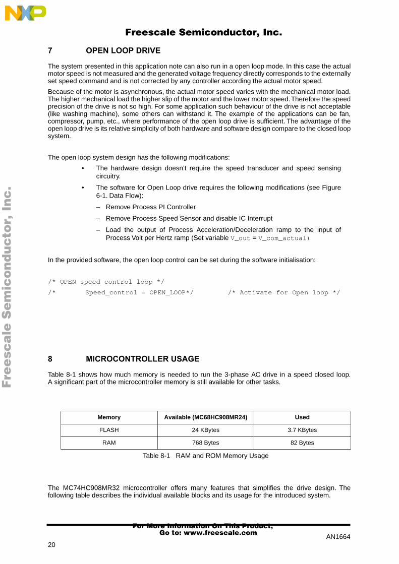
Table 8-1 shows how much memory is needed to run the 3-phase AC drive in a speed closed loop.A significant part of the microcontroller memory is still available for other tasks.
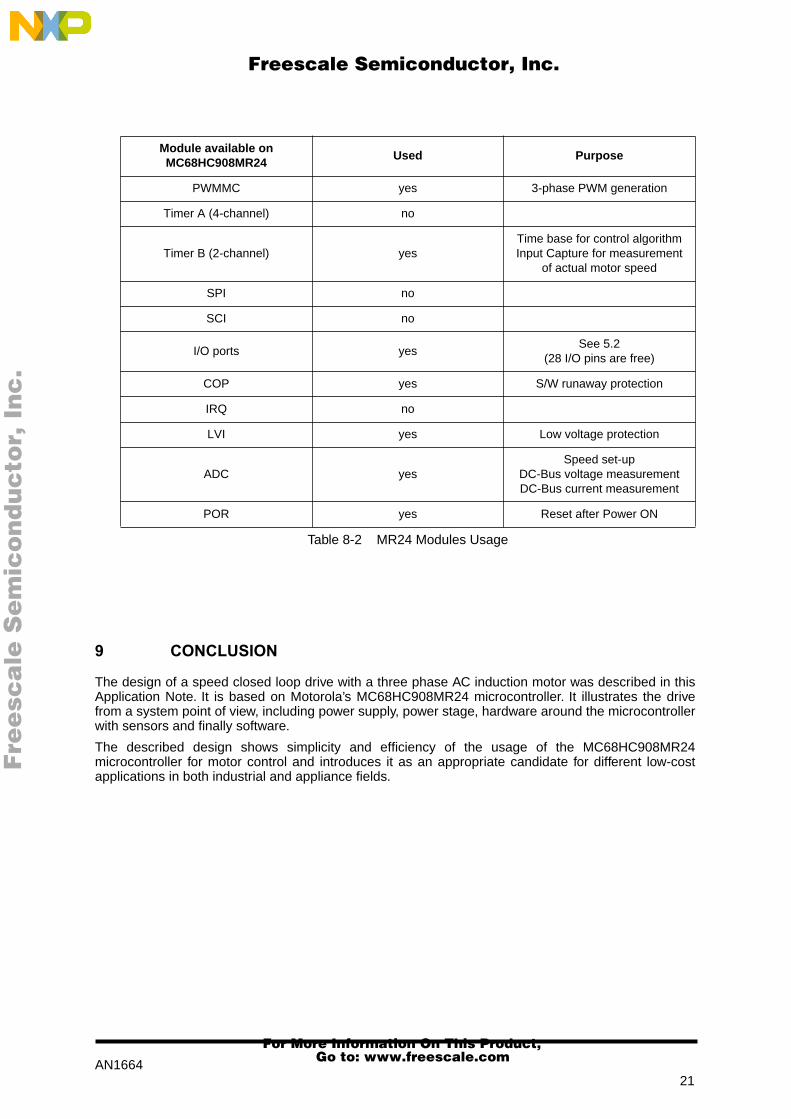
The MC74HC908MR32 microcontroller offers many features that simplifies the drive design. Thefollowing table describes the individual available blocks and its usage for the introduced system.
Memory Available (MC68HC908MR24) Used
FLASH 24 KBytes 3.7 KBytes
RAM 768 Bytes 82 Bytes
Table 8-1 RAM and ROM Memory Usage
Fre
esc
ale
Se
mic
on
du
cto
r, I
Freescale Semiconductor, Inc.
For More Information On This Product, Go to: www.freescale.com
nc
...
AN166421
9 CONCLUSION
The design of a speed closed loop drive with a three phase AC induction motor was described in thisApplication Note. It is based on Motorola’s MC68HC908MR24 microcontroller. It illustrates the drivefrom a system point of view, including power supply, power stage, hardware around the microcontrollerwith sensors and finally software.
The described design shows simplicity and efficiency of the usage of the MC68HC908MR24microcontroller for motor control and introduces it as an appropriate candidate for different low-costapplications in both industrial and appliance fields.
Module available onMC68HC908MR24
Used Purpose
PWMMC yes 3-phase PWM generation
Timer A (4-channel) no
Timer B (2-channel) yesTime base for control algorithmInput Capture for measurement
of actual motor speed
SPI no
SCI no
I/O ports yesSee 5.2
(28 I/O pins are free)
COP yes S/W runaway protection
IRQ no
LVI yes Low voltage protection
ADC yesSpeed set-up
DC-Bus voltage measurementDC-Bus current measurement
POR yes Reset after Power ON
Table 8-2 MR24 Modules Usage
Fre
esc
ale
Se
mic
on
du
cto
r, I
Freescale Semiconductor, Inc.
For More Information On This Product, Go to: www.freescale.com
nc
...
AN166422
APPENDIX A
A.1 Schematics
Figure A-1. MC68HC908MR24 Microcontroller Board
Fre
esc
ale
Se
mic
on
du
cto
r, I
Freescale Semiconductor, Inc.
For More Information On This Product, Go to: www.freescale.com
nc
...

AN166423
Figure A-2. Sensor Board 1 of 3 (Block Schematic)
Figure A-3. Sensor Board 2 of 3 (Speed Sensing)
Fre
esc
ale
Se
mic
on
du
cto
r, I
Freescale Semiconductor, Inc.
For More Information On This Product, Go to: www.freescale.com
nc
...

AN166424
Figure A-4. Sensor Board 3 of 3 (Voltage and Current Sensing)
Fre
esc
ale
Se
mic
on
du
cto
r, I
Freescale Semiconductor, Inc.
For More Information On This Product, Go to: www.freescale.com
nc
...

AN166425
Figure A-5. Power Stage Board
Fre
esc
ale
Se
mic
on
du
cto
r, I
Freescale Semiconductor, Inc.
For More Information On This Product, Go to: www.freescale.com
nc
...

AN166426
A.2 Part List of Components
All tolerances ±10% for capacitors and ±1% for resistors, unless otherwise specified.
Table A-1 Part List - Microcontroller Board
Component Value/Rating Description Quantity
U1 MC68HC908MR24FU Microcontroller 1
D1 - D3 LED LED 3
X1 4.9152 MHz Crystal 1
R1 - R3 1k Resistor 3
R4 10k Resistor 1
R5 10M Resistor 1
P1 10k Potentiometer 1
C1 - C5, C8 - C10 100nF Capacitor 8
C6, C7 20pF Capacitor 2
C11 10µF/16V Electrolytic Capacitor 1
J1 Con40 Connector 1
J2 Con3 Connector 1
SW1, SW2 - Switch 2
SW3 - 2 bit DIP Switch 1
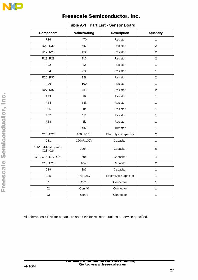
Table A-1 Part List - Sensor Board
Component Value/Rating Description Quantity
U3, U10 LM339 Comparator 2
U6 MC34074 Operational Amplifier 1
U7, U9 HCPL7800 Isolation Amplifier 2
U8 MC33202P Operational Amplifier 1
D1 1N5817 Diode 1
D2, D3 5V6 Zener Diode 2
R11 100k Resistor 1
R12 15k Resistor 1
R13 10k Resistor 1
R14 6k8 Resistor 1
R15, R18, R21, R28, R31
2k2 Resistor 5
Fre
esc
ale
Se
mic
on
du
cto
r, I
Freescale Semiconductor, Inc.
For More Information On This Product, Go to: www.freescale.com
nc
...
AN166427
All tolerances ±10% for capacitors and ±1% for resistors, unless otherwise specified.
R16 470 Resistor 1
R20, R30 4k7 Resistor 2
R17, R23 13k Resistor 2
R19, R29 1k0 Resistor 2
R22 22 Resistor 1
R24 22k Resistor 1
R25, R36 12k Resistor 2
R26 100 Resistor 1
R27, R32 2k0 Resistor 2
R33 10 Resistor 1
R34 33k Resistor 1
R35 1k Resistor 1
R37 1M Resistor 1
R38 5k Resistor 1
P1 4k7 Trimmer 1
C10, C26 100µF/16V Electrolytic Capacitor 2
C11 220nF/100V Capacitor 1
C12, C14, C18, C22, C23, C24
100nF Capacitor 6
C13, C16, C17, C21 150pF Capacitor 4
C15, C20 10nF Capacitor 2
C19 3n3 Capacitor 1
C25 47µF/25V Electrolytic Capacitor 1
J1 Con15 Connector 1
J2 Con 40 Connector 1
J3 Con 2 Connector 1
Table A-1 Part List - Sensor Board
Component Value/Rating Description Quantity
Fre
esc
ale
Se
mic
on
du
cto
r, I
Freescale Semiconductor, Inc.
For More Information On This Product, Go to: www.freescale.com
nc
...

AN166428
All tolerances ±10% for capacitors and ±1% for resistors, unless otherwise specified.
Table A-1 Part List - Three Phase HV Power Board
Component Value/Rating Description Quantity
U2, U3, U4, U5, U6, U7, U13
HP4504 Optocoupler 6
U8, U9, U10 IR2112 Gate Driver 3
Q1 - Q6 MGP8N60ED Copack IGBT 6
DZ1 - DZ6 22V Zener Diode 6
D7, D8, D9, D10, D11, D12
MUR160 Diode 6
D13 1N4004 Diode 1
R1, R5, R9 1R0 Resistor 3
R2, R4, R6, R8, R10, R12
100R Resistor 6
R3, R7, R11 22R Resistor 3
R13 0.1R Current Sense Resistor 1
R15, R16, R17 1M Resistor 3
R18 27k Resistor 1
R19 - R24, R31 2k2 Resistor 7
R25 - R30 330 Resistor 6
R32 620 Resistor 1
RN1 8x10k Resistor Net 1
C1 - C6 220nF/63V Capacitor 6
C7a, C7b 4n7/630V- Capacitor 2
C8 100µF/400V Electrolytic Capacitor 1
C10 - C16, C18, C21, C25, C31
100nF Capacitor 11
C19, C24 100µF/50V Electrolytic Capacitor 2
C20 1000µF/35V Capacitor 1
J1 Con40 Connector 1
J2, J3 Con4 Connector 2
J4 Con3 Connector 1
J5 Con2 Connector 1
J6 Con15 Connector 1
Fre
esc
ale
Se
mic
on
du
cto
r, I
Freescale Semiconductor, Inc.
For More Information On This Product, Go to: www.freescale.com
nc
...

AN166429
APPENDIX B
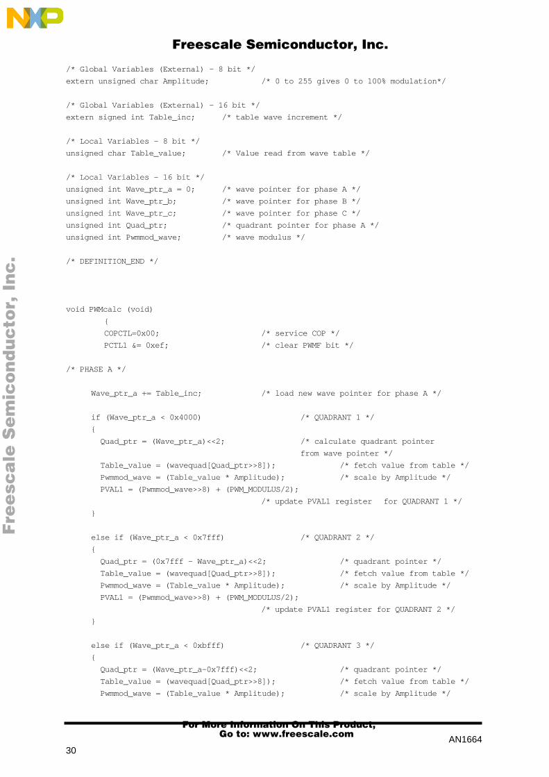
B.1 Subroutine ÒPWM CalculationÓ
/*
* Project: CLOSED LOOP 3-PHASE AC DRIVE
*
* Microcontroller: Motorola MC68HC908MR24
*
* Module: PWMCALC.C
* Revision/Date: 1.0 / June 1998
* Description: This routine is 2nd level ISR responding to PWM interrupt.
* Input: New waveform parameters Incval and Amplitude
* Output: Load 3 PWM registers PVAL1, PVAL3, PVAL5
*
* Compiler: C Cross Compiler - COSMIC Software Inc.
*
* Author: Radim VISINKA
* Company: MOTOROLA SPS
* Roznov System Application Laboratory
* Roznov pod Radhostem, Czech Republic
*
* ===================================================================
*
* Copyright (c): MOTOROLA Inc.,1998, All rights reserved.
*
* ====================================================================
* THIS SOFTWARE IS PROVIDED BY MOTOROLA RSAL "AS IS" AND ANY
* EXPRESSED OR IMPLIED WARRANTIES, INCLUDING, BUT NOT LIMITED TO, THE
* IMPLIED WARRANTIES OF MERCHANTABILITY AND FITNESS FOR A PARTICULAR
* PURPOSE ARE DISCLAIMED. IN NO EVENT SHALL MOTOROLA RSAL OR
* ITS CONTRIBUTORS BE LIABLE FOR ANY DIRECT, INDIRECT, INCIDENTAL,
* SPECIAL, EXEMPLARY, OR CONSEQUENTIAL DAMAGES (INCLUDING, BUT
* NOT LIMITED TO, PROCUREMENT OF SUBSTITUTE GOODS OR SERVICES;
* LOSS OF USE, DATA, OR PROFITS; OR BUSINESS INTERRUPTION)
* HOWEVER CAUSED AND ON ANY THEORY OF LIABILITY, WHETHER IN CONTRACT,
* STRICT LIABILITY, OR TORT (INCLUDING NEGLIGENCE OR OTHERWISE)
* ARISING IN ANY WAY OUT OF THE USE OF THIS SOFTWARE, EVEN IF ADVISED
* OF THE POSSIBILITY OF SUCH DAMAGE.
* ====================================================================
*/
/* DEFINITION_START */
/* Include Header Files */
#include <mr24io.h> /* file contains input/output file */
#include "CONST.H“ /* file contains global constants and definitions */
#include <3rdhquad.h> /* contains wave table for one quadrant*/
/* 3rdhquad.h for sine wave with third harmonic */
/* constant unsigned int wavequad[256] */
Fre
esc
ale
Se
mic
on
du
cto
r, I
Freescale Semiconductor, Inc.
For More Information On This Product, Go to: www.freescale.com
nc
...
AN166430
/* Global Variables (External) - 8 bit */
extern unsigned char Amplitude; /* 0 to 255 gives 0 to 100% modulation*/
/* Global Variables (External) - 16 bit */
extern signed int Table_inc; /* table wave increment */
/* Local Variables - 8 bit */
unsigned char Table_value; /* Value read from wave table */
/* Local Variables - 16 bit */
unsigned int Wave_ptr_a = 0; /* wave pointer for phase A */
unsigned int Wave_ptr_b; /* wave pointer for phase B */
unsigned int Wave_ptr_c; /* wave pointer for phase C */
unsigned int Quad_ptr; /* quadrant pointer for phase A */
unsigned int Pwmmod_wave; /* wave modulus */
/* DEFINITION_END */
void PWMcalc (void)
{
COPCTL=0x00; /* service COP */
PCTL1 &= 0xef; /* clear PWMF bit */
/* PHASE A */
Wave_ptr_a += Table_inc; /* load new wave pointer for phase A */
if (Wave_ptr_a < 0x4000) /* QUADRANT 1 */
{
Quad_ptr = (Wave_ptr_a)<<2; /* calculate quadrant pointer
from wave pointer */
Table_value = (wavequad[Quad_ptr>>8]); /* fetch value from table */
Pwmmod_wave = (Table_value * Amplitude); /* scale by Amplitude */
PVAL1 = (Pwmmod_wave>>8) + (PWM_MODULUS/2);
/* update PVAL1 register for QUADRANT 1 */
}
else if (Wave_ptr_a < 0x7fff) /* QUADRANT 2 */
{
Quad_ptr = (0x7fff - Wave_ptr_a)<<2; /* quadrant pointer */
Table_value = (wavequad[Quad_ptr>>8]); /* fetch value from table */
Pwmmod_wave = (Table_value * Amplitude); /* scale by Amplitude */
PVAL1 = (Pwmmod_wave>>8) + (PWM_MODULUS/2);
/* update PVAL1 register for QUADRANT 2 */
}
else if (Wave_ptr_a < 0xbfff) /* QUADRANT 3 */
{
Quad_ptr = (Wave_ptr_a-0x7fff)<<2; /* quadrant pointer */
Table_value = (wavequad[Quad_ptr>>8]); /* fetch value from table */
Pwmmod_wave = (Table_value * Amplitude); /* scale by Amplitude */
Fre
esc
ale
Se
mic
on
du
cto
r, I
Freescale Semiconductor, Inc.
For More Information On This Product, Go to: www.freescale.com
nc
...

AN166431
PVAL1 = (PWM_MODULUS/2) - (Pwmmod_wave>>8);
/* update PVAL1 register for QUADRANT 3 */
}
else /* (Wave_ptr_a < 0xffff) QUADRANT 4 */
{
Quad_ptr = (0xffff - Wave_ptr_a)<<2; /* quadrant pointer */
Table_value = (wavequad[Quad_ptr>>8]); /* fetch value from table */
Pwmmod_wave = (Table_value * Amplitude); /* scale by Amplitude */
PVAL1 = (PWM_MODULUS/2) - (Pwmmod_wave>>8);
/* update PVAL1 register for QUADRANT 4 */
}
/* PVAL2 is updated automaticaly because of COMPLEMENTARY PWM MODE */
/* PHASE B */
Wave_ptr_b = Wave_ptr_a + 0x5555;
if (Wave_ptr_b < 0x4000) /* QUADRANT 1 */
{
Quad_ptr = Wave_ptr_b<<2; /* quadrant pointer */
Table_value = (wavequad[Quad_ptr>>8]); /* fetch value from table */
Pwmmod_wave = (Table_value * Amplitude); /* scale by Amplitude */
PVAL3 = (Pwmmod_wave>>8) + (PWM_MODULUS/2);
/* update PVAL3 register for QUADRANT 1 */
}
else if (Wave_ptr_b < 0x7fff) /* QUADRANT 2 */
{
Quad_ptr = (0x7fff - Wave_ptr_b)<<2; /* quadrant pointer */
Table_value = (wavequad[Quad_ptr>>8]); /* fetch value from table */
Pwmmod_wave = (Table_value * Amplitude); /* scale by Amplitude */
PVAL3 = (Pwmmod_wave>>8) + (PWM_MODULUS/2);
/* update PVAL3 register for QUADRANT 2 */
}
else if (Wave_ptr_b < 0xbfff) /* QUADRANT 3 */
{
Quad_ptr = (Wave_ptr_b - 0x7fff)<<2; /* quadrant pointer */
Table_value = (wavequad[Quad_ptr>>8]); /* fetch value from table */
Pwmmod_wave = (Table_value * Amplitude); /* scale by Amplitude */
PVAL3 = (PWM_MODULUS/2) - (Pwmmod_wave>>8);
/* update PVAL3 register for QUADRANT 3 */
}
else /* (Wave_ptr_b < 0xffff) QUADRANT 4 */
{
Quad_ptr = (0xffff - Wave_ptr_b)<<2; /* quadrant pointer */
Table_value = (wavequad[Quad_ptr>>8]); /* fetch value from table */
Pwmmod_wave = (Table_value * Amplitude); /* scale by Amplitude */
PVAL3 = (PWM_MODULUS/2) - (Pwmmod_wave>>8);
/* update PVAL3 register for QUADRANT 4 */
Fre
esc
ale
Se
mic
on
du
cto
r, I
Freescale Semiconductor, Inc.
For More Information On This Product, Go to: www.freescale.com
nc
...

AN166432
}
/* PVAL4 is updated automaticaly because of COMPLEMENTARY PWM MODE */
/* PHASE C */
Wave_ptr_c = Wave_ptr_a + 0xaaaa;
if (Wave_ptr_c < 0x4000) /* QUADRANT 1 */
{
Quad_ptr = Wave_ptr_c<<2; /* quadrant pointer */
Table_value = (wavequad[Quad_ptr>>8]); /* fetch value from table */
Pwmmod_wave = (Table_value * Amplitude); /* scale by Amplitude */
PVAL5 = (Pwmmod_wave>>8) + (PWM_MODULUS/2);
/* update PVAL5 register for QUADRANT 1 */
}
else if (Wave_ptr_c < 0x7fff) /* QUADRANT 2 */
{
Quad_ptr = (0x7fff - Wave_ptr_c)<<2; /* quadrant pointer */
Table_value = (wavequad[Quad_ptr>>8]); /* fetch value from table */
Pwmmod_wave = (Table_value * Amplitude); /* scale by Amplitude */
PVAL5 = (Pwmmod_wave>>8) + (PWM_MODULUS/2);
/* update PVAL5 register
for QUADRANT 2 */
}
else if (Wave_ptr_c < 0xbfff) /* QUADRANT 3 */
{
Quad_ptr = (Wave_ptr_c - 0x7fff)<<2; /* quadrant pointer */
Table_value = (wavequad[Quad_ptr>>8]); /* fetch value from table */
Pwmmod_wave = (Table_value * Amplitude); /* scale by Amplitude */
PVAL5 = (PWM_MODULUS/2) - (Pwmmod_wave>>8);
/* update PVAL5 register for QUADRANT 3 */
}
else /* (Wave_ptr_c < 0xffff) QUADRANT 4 */
{
Quad_ptr = (0xffff - Wave_ptr_c)<<2; /* quadrant pointer */
Table_value = (wavequad[Quad_ptr>>8]); /* fetch value from table */
Pwmmod_wave = (Table_value * Amplitude); /* scale by Amplitude */
PVAL5 = (PWM_MODULUS/2) - (Pwmmod_wave>>8);
/* update PVAL5 register for QUADRANT 4 */
}
/* PVAL6 is updated automaticaly because of COMPLEMENTARY PWM MODE */
PCTL1 |= 0x02; /* set LDOK bit */
}
Fre
esc
ale
Se
mic
on
du
cto
r, I
Freescale Semiconductor, Inc.
For More Information On This Product, Go to: www.freescale.com
nc
...
AN166433
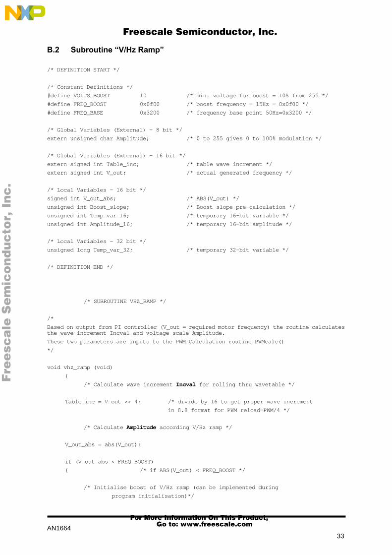
B.2 Subroutine ÒV/Hz RampÓ
/* DEFINITION START */
/* Constant Definitions */
#define VOLTS_BOOST 10 /* min. voltage for boost = 10% from 255 */
#define FREQ_BOOST 0x0f00 /* boost frequency = 15Hz = 0x0f00 */
#define FREQ_BASE 0x3200 /* frequency base point 50Hz=0x3200 */
/* Global Variables (External) - 8 bit */
extern unsigned char Amplitude; /* 0 to 255 gives 0 to 100% modulation */
/* Global Variables (External) - 16 bit */
extern signed int Table_inc; /* table wave increment */
extern signed int V_out; /* actual generated frequency */
/* Local Variables - 16 bit */
signed int V_out_abs; /* ABS(V_out) */
unsigned int Boost_slope; /* Boost slope pre-calculation */
unsigned int Temp_var_16; /* temporary 16-bit variable */
unsigned int Amplitude_16; /* temporary 16-bit amplitude */
/* Local Variables - 32 bit */
unsigned long Temp_var_32; /* temporary 32-bit variable */
/* DEFINITION END */
/* SUBROUTINE VHZ_RAMP */
/*
Based on output from PI controller (V_out = required motor frequency) the routine calculatesthe wave increment Incval and voltage scale Amplitude.
These two parameters are inputs to the PWM Calculation routine PWMcalc()
*/
void vhz_ramp (void)
{
/* Calculate wave increment Incval for rolling thru wavetable */
Table_inc = V_out >> 4; /* divide by 16 to get proper wave increment
in 8.8 format for PWM reload=PWM/4 */
/* Calculate Amplitude according V/Hz ramp */
V_out_abs = abs(V_out);
if (V_out_abs < FREQ_BOOST)
{ /* if ABS(V_out) < FREQ_BOOST */
/* Initialise boost of V/Hz ramp (can be implemented during
program initialisation)*/
Fre
esc
ale
Se
mic
on
du
cto
r, I
Freescale Semiconductor, Inc.
For More Information On This Product, Go to: www.freescale.com
nc
...

AN166434
Boost_slope = (FREQ_BOOST<<16)/(FREQ_BASE) - (VOLTS_BOOST * 0x028f);
/* 0x028f scales the range of VOLTS_BOOST from 100% to 0xffff */
Temp_var_32 = (long)Boost_slope * (long)V_out_abs;
Temp_var_16 = Temp_var_32 / FREQ_BOOST;
Amplitude_16 = Temp_var_16 + (VOLTS_BOOST * 0x028f);
Amplitude = Amplitude_16>>8; /* 16 to 8 bit */
}
else
{
if (V_out_abs < FREQ_BASE)
{ /* if FREQ_BOOST < ABS(V_out) < FREQ_BASE */
Amplitude = V_out_abs/(FREQ_BASE>>8);
}
else /* if ABS(V_out) > BASE_FREQ*/
{
Amplitude = 0xff;
}
}
}
Fre
esc
ale
Se
mic
on
du
cto
r, I
Freescale Semiconductor, Inc.
For More Information On This Product, Go to: www.freescale.com
nc
...

AN166435
Fre
esc
ale
Se
mic
on
du
cto
r, I
Freescale Semiconductor, Inc.
For More Information On This Product, Go to: www.freescale.com
nc
...
AN1664/D◊
Fre
esc
ale
Se
mic
on
du
cto
r, I
Freescale Semiconductor, Inc.
For More Information On This Product, Go to: www.freescale.com
nc
...