Embed Size (px)
Citation preview
Properties · Processing · Applications
Low-Alloyed Copper Alloys

2 | KUPFERINSTITUT.DE
DKI-i8-2018
KUPFERINSTITUT.DE | 3
1. Introduction 4
1.1 Classification 6 1.2 Standardized low-alloyed coppers and their applications 7
2. Copper alloys with very high electrical conductivity and good machinability 9
2.1 Tellurium copper 9 2.2 Copper-lead-phosphorus 10 2.3 Copper-sulfur 11
3. Copper alloys with very high electrical conductivity and high softening temperature 12
3.1 Copper-silver 12 3.2 Copper-zirconium 13 3.3 Copper-zinc 15 4. Copper alloys with high or moderate electrical conductivity and medium strength 16
4.1 Copper-magnesium 16 4.2 Copper-iron 17 4.3 Copper-chromium 19 4.4 Copper-chromium-zirconium 20 4.5 Copper-nickel-phosphorus 22 4.6 Copper-tin 24
5. Copper alloys with moderate electrical conductivity and high strength 25
5.1 Copper-beryllium 25 5.2 Copper-cobalt-beryllium / Copper-nickel-beryllium 26 5.3 Copper-nickel-silicon 27 5.4 Copper-nickel-tin 29
6. Copper alloys for non-electrical applications 30
6.1 Copper-manganese 30 6.2 Copper-silicon and copper-silicon-manganese 31 7. Dispersion-strengthened alloys 32 8. Literature / Technical standards 33
Contents
4 | KUPFERINSTITUT.DE
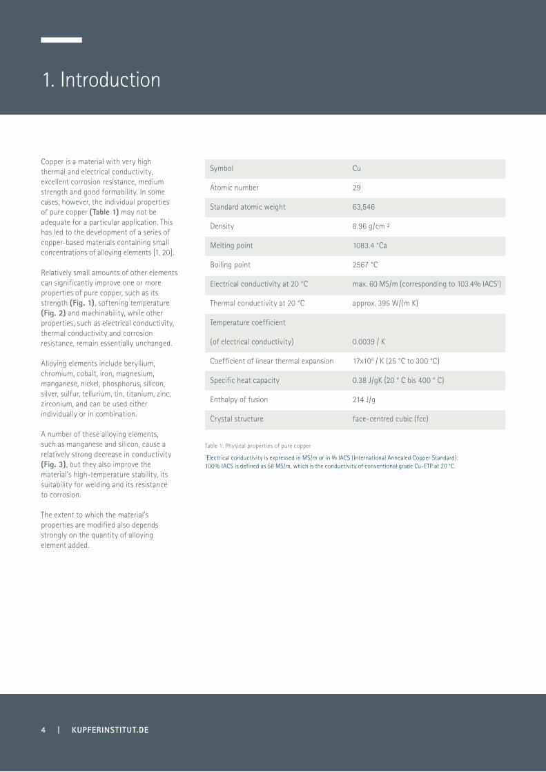
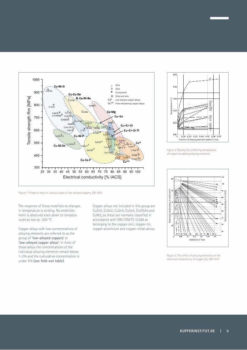
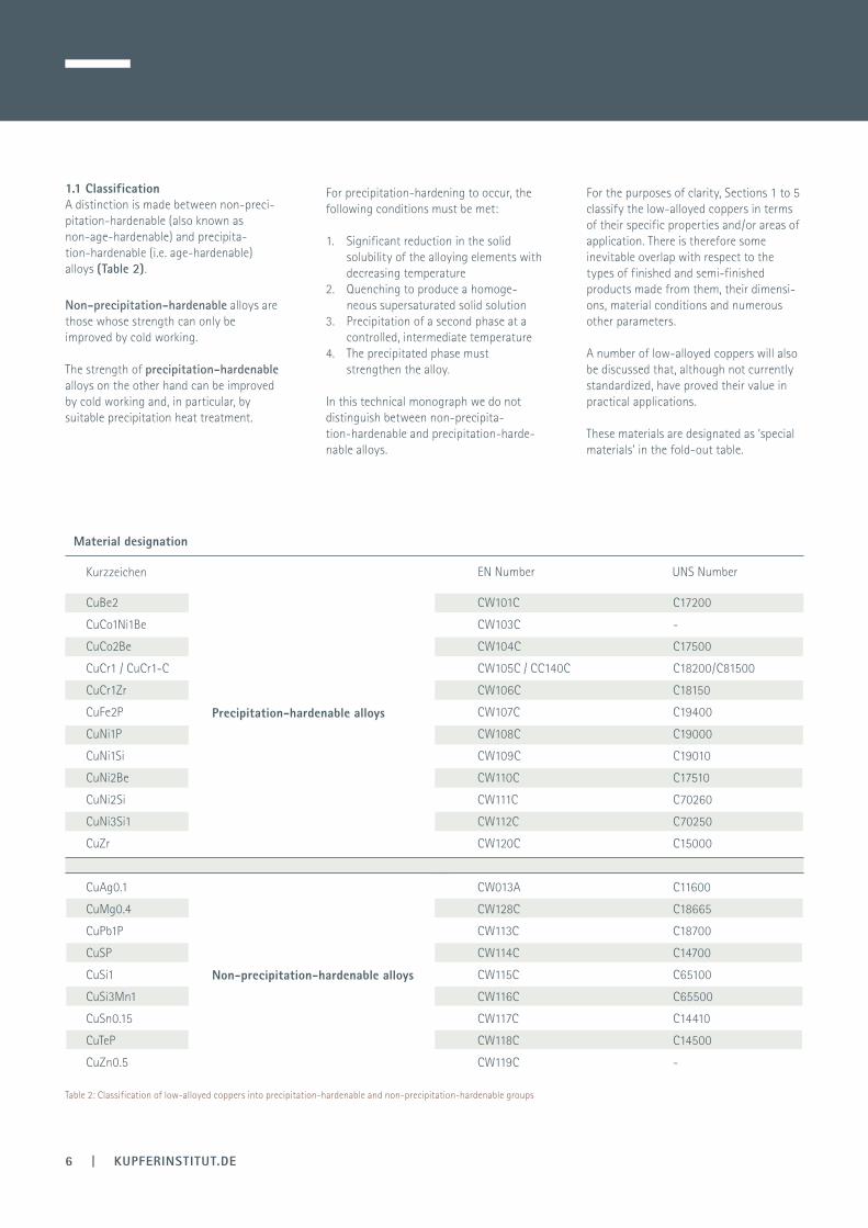
Copper is a material with very high thermal and electrical conductivity, excellent corrosion resistance, medium strength and good formability. In some cases, however, the individual properties of pure copper (Table 1) may not be adequate for a particular application. This has led to the development of a series of copper-based materials containing small concentrations of alloying elements [1, 20]. Relatively small amounts of other elements can significantly improve one or more properties of pure copper, such as its strength (Fig. 1), softening temperature (Fig. 2) and machinability, while other properties, such as electrical conductivity, thermal conductivity and corrosion resistance, remain essentially unchanged.
Alloying elements include beryllium, chromium, cobalt, iron, magnesium, manganese, nickel, phosphorus, silicon, silver, sulfur, tellurium, tin, titanium, zinc, zirconium, and can be used either individually or in combination.
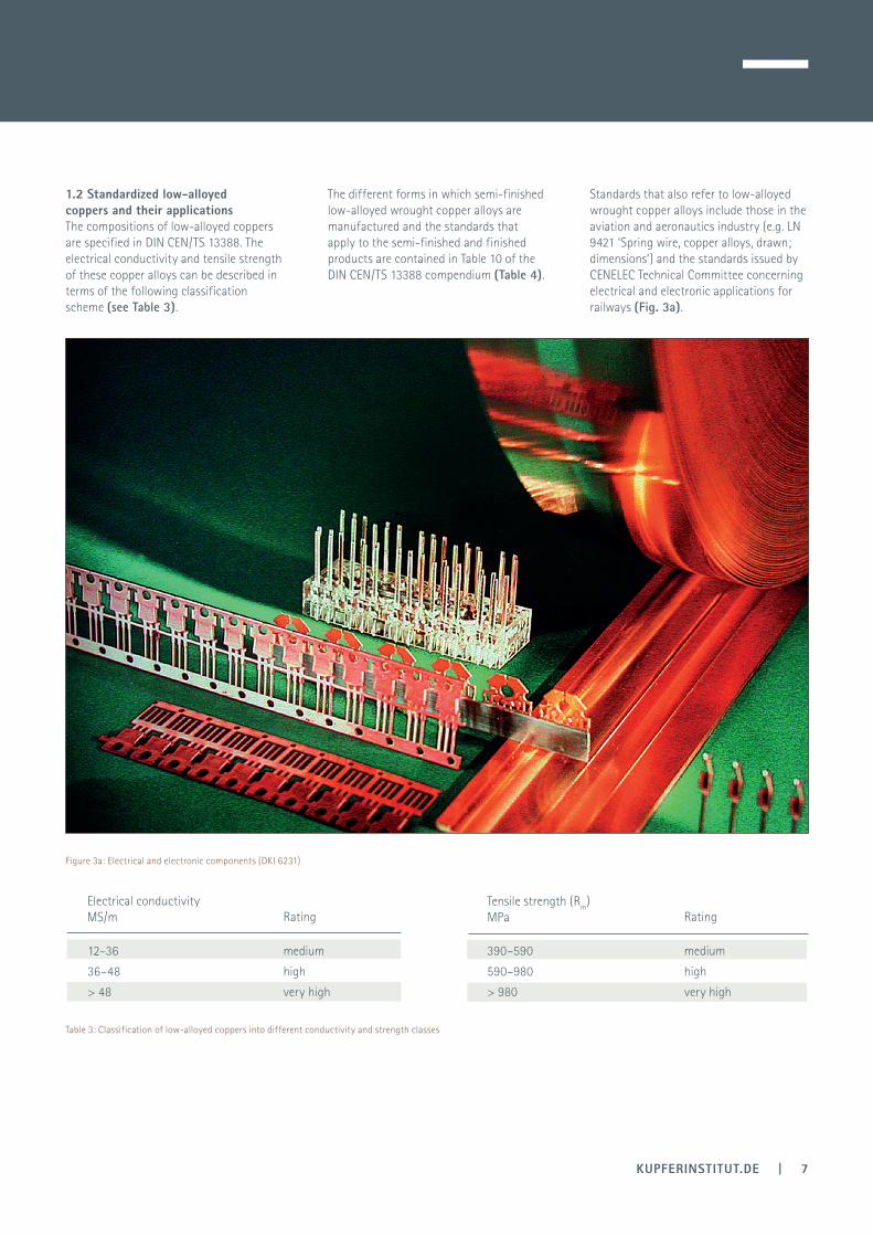
A number of these alloying elements, such as manganese and silicon, cause a relatively strong decrease in conductivity (Fig. 3), but they also improve the material’s high-temperature stability, its suitability for welding and its resistance to corrosion.
The extent to which the material’s properties are modified also depends strongly on the quantity of alloying element added.
1. Introduction
Symbol
Atomic number
Standard atomic weight
Density
Melting point
Boiling point
Electrical conductivity at 20 °C
Thermal conductivity at 20 °C
Temperature coefficient
(of electrical conductivity)
Coefficient of linear thermal expansion
Specific heat capacity
Enthalpy of fusion
Crystal structure
Table 1: Physical properties of pure copper
1Electrical conductivity is expressed in MS/m or in % IACS (International Annealed Copper Standard): 100% IACS is defined as 58 MS/m, which is the conductivity of conventional grade Cu-ETP at 20 °C.
Cu
29
63,546
8.96 g/cm ²
1083.4 °Ca
2567 °C
max. 60 MS/m (corresponding to 103.4% IACS1)
approx. 395 W/(m⋅K)
0.0039 / K
17x106 / K (25 °C to 300 °C)
0.38 J/gK (20 ° C bis 400 ° C)
214 J/g
face-centred cubic (fcc)
KUPFERINSTITUT.DE | 5
The response of these materials to changes in temperature is striking. No embrittle-ment is observed even down to tempera-tures as low as -200 °C.
Copper alloys with low concentrations of alloying elements are referred to as the group of ‘low-alloyed coppers’ or ‘low-alloyed copper alloys’. In most of these alloys the concentrations of the individual alloying elements remain below 1–2% and the cumulative concentration is under 5% (see fold-out table).
Copper alloys not included in this group are CuZn5, CuSn2, CuSn4, CuSn5, CuAl5As and CuNi2, as these are normally classified in accordance with DIN CEN/TS 13388 as belonging to the copper-zinc, copper-tin, copper-aluminium and copper-nickel alloys.
Figure 1: Property map for various types of low-alloyed coppers, DKI 4501
Figure 2: Raising the softening temperature of copper by adding alloying elements
Figure 3: The effect of alloying elements on the electrical conductivity of copper [2], DKI 3373
Electrical conductivity [% IACS]
Wire
Strip
Component
Strip and wire
Low-alloyed copper alloys
Free-mechaning copper alloys
Tens
ile s
treng
th R
m [M
Pa]
Fraction of alloying element added in %wt.
Tem
pera
ture
in °
CE
lect
rical
con
duct
ivity
in m
/(Ω·m
m²)
Ele
ctric
al c
ondu
ctiv
ity in
% IA
CS
Additives in %wt.
CuBe2
CuCo1Ni1Be
CuCo2Be
CuCr1 / CuCr1-C
CuCr1Zr
CuFe2P
CuNi1P
CuNi1Si
CuNi2Be
CuNi2Si
CuNi3Si1
CuZr
CuAg0.1
CuMg0.4
CuPb1P
CuSP
CuSi1
CuSi3Mn1
CuSn0.15
CuTeP
CuZn0.5
CW101C
CW103C
CW104C
CW105C / CC140C
CW106C
CW107C
CW108C
CW109C
CW110C
CW111C
CW112C
CW120C
CW013A
CW128C
CW113C
CW114C
CW115C
CW116C
CW117C
CW118C
CW119C
6 | KUPFERINSTITUT.DE
1.1 ClassificationA distinction is made between non-preci-pitation-hardenable (also known as non-age-hardenable) and precipita-tion-hardenable (i.e. age-hardenable) alloys (Table 2).
Non-precipitation-hardenable alloys are those whose strength can only be improved by cold working.
The strength of precipitation-hardenable alloys on the other hand can be improved by cold working and, in particular, by suitable precipitation heat treatment.
For precipitation-hardening to occur, the following conditions must be met:
1. Significant reduction in the solid solubility of the alloying elements with decreasing temperature2. Quenching to produce a homoge- neous supersaturated solid solution3. Precipitation of a second phase at a controlled, intermediate temperature 4. The precipitated phase must strengthen the alloy.
In this technical monograph we do not distinguish between non-precipita-tion-hardenable and precipitation-harde-nable alloys.
For the purposes of clarity, Sections 1 to 5 classify the low-alloyed coppers in terms of their specific properties and/or areas of application. There is therefore some inevitable overlap with respect to the types of finished and semi-finished products made from them, their dimensi-ons, material conditions and numerous other parameters.
A number of low-alloyed coppers will also be discussed that, although not currently standardized, have proved their value in practical applications.
These materials are designated as ‘special materials’ in the fold-out table.
Table 2: Classification of low-alloyed coppers into precipitation-hardenable and non-precipitation-hardenable groups
Material designation
Kurzzeichen EN Number UNS Number
Non-precipitation-hardenable alloys
Precipitation-hardenable alloys
C17200
-
C17500
C18200/C81500
C18150
C19400
C19000
C19010
C17510
C70260
C70250
C15000
C11600
C18665
C18700
C14700
C65100
C65500
C14410
C14500
-
KUPFERINSTITUT.DE | 7
1.2 Standardized low-alloyed coppers and their applications The compositions of low-alloyed coppers are specified in DIN CEN/TS 13388. The electrical conductivity and tensile strength of these copper alloys can be described in terms of the following classification scheme (see Table 3).
12–36
36–48
> 48
medium
high
very high
390–590
590–980
> 980
Electrical conductivity MS/m Rating Rating
Tensile strength (Rm) MPa
medium
high
very high
Table 3: Classification of low-alloyed coppers into different conductivity and strength classes
Figure 3a: Electrical and electronic components (DKI 6231)
The different forms in which semi-finished low-alloyed wrought copper alloys are manufactured and the standards that apply to the semi-finished and finished products are contained in Table 10 of the DIN CEN/TS 13388 compendium (Table 4).
Standards that also refer to low-alloyed wrought copper alloys include those in the aviation and aeronautics industry (e.g. LN 9421 ‘Spring wire, copper alloys, drawn; dimensions’) and the standards issued by CENELEC Technical Committee concerning electrical and electronic applications for railways (Fig. 3a).
8 | KUPFERINSTITUT.DE
Cast products are defined in the DIN EN 1982 standard. The only low-alloyed copper casting alloy included in DIN EN 1982 is the copper chromium casting alloy CuCr1-C.
Material properties specified in the standard include composition, mechanical properties and electrical conductivity.
Material designation
Flat-rolled products Pipes and tubes Rods, shaped cross-sections and wires C*
Symbol Number
EN 1
172
EN 1
652
EN 1
653
EN 1
654
EN 1
758
EN 1
3148
EN 1
3599
EN 1
4436
EN 1
057
EN 1
2449
EN 1
2450
EN 1
2451
EN 1
2452
EN 1
2735
-1
EN 1
2735
-2
EN 1
3348
EN 1
3349
EN 1
3600
EN 1
977
EN 1
2163
EN 1
2164
EN 1
2166
EN 1
2167
EN 1
2168
EN 1
3601
EN 1
3602
EN 1
3605
EN 1
2165
EN 1
2420
EN 1
3604
CuAg0.10P CW016A x x x x x
CuBe1.7 CW100C x x x
CuBe2 CW101C x x x x x x x x x
CuCo1Ni1Be CW103C x x x x x x
CuCo2Be CW104C x x x x x x x x x
CuCr1 CW105C x x x x
CuCr1Zr CW106C x x x x x
CuFe2P CW107C x x x x x
CuNi1P CW108C x
CuNi1Si CW109C x x x
CuNi2Be CW110C x x x x x x x
CuNi2Si CW111C x x x x x x x x
CuNi3Si1 CW112C x x x
CuPb1P CW113C x
CuSP CW114C x x
CuSi1 CW115C x
CuSi3Mn1 CW116C x x
CuSn0.15 CW117C x x x
CuTeP CW118C x x x
CuZn0,5 CW119C x x x x
CuZr CW120C x x x x x
An important group of low-alloyed coppers alloys are those with a high to intermediate conductivity that are used primarily in electrical engineering applications [3, 21]. Examples include copper-silver, copper-chro-mium-zirconium and copper-magnesium.
However, there are other low-alloyed coppers for which electrical conductivity is not the key consideration and these materials, such as copper-silicon-manganese, tend to be used in mechanical construction applications.
Forging stock and forged products
Types of products and available materials
Table 4: Product forms for standardized low-alloyed coppers (based on Table 10 in DIN CEN/TS 13388)*C: Copper plates, sheets, strips, seamless tubing, rods, wires and shaped cross-sections for electronic tubes and valves, semiconductor components and for applications in vacuum technology
KUPFERINSTITUT.DE | 9
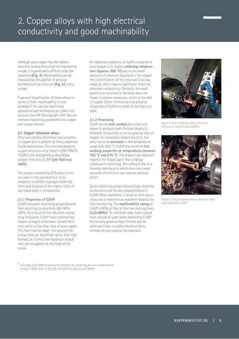
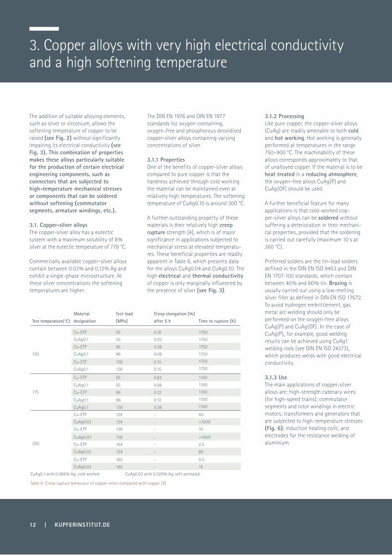
Although pure copper has the highest electrical conductivity of all the engineering metals, it is particularly difficult to be free machined (Fig. 4). Machinability can be improved by the addition of alloying elements such as tellurium (Fig. 5), sulfur or lead.
A general classification of these alloys in terms of their machinability is only possible if the various machining operations and techniques are taken into account (see DKI Monograph i018: Recom-mended machining parameters for copper and copper alloys).
2.1 Copper-tellurium alloysTellurium exhibits extremely low solubility in copper and is present as finely dispersed Cu2Te precipitates. The only standardized copper-tellurium alloy listed in DIN CEN/TS 13388 is the phosphorous deoxidized oxygen-free alloy CuTeP (see fold-out table).
The oxygen-containing CuTe alloy is not included in the standard due to its tendency to exhibit hydrogen embrittle-ment and because of the higher levels of tool wear when it is machined.
2.1.1 Properties of CuTeP CuTeP has good machining properties and high electrical conductivity (90–96% IACS). As a result of the tellurium-contai-ning inclusions, CuTeP has a notched-bar impact strength of between 39 and 78 J/cm², which is less than that of pure copper This fact must be taken into account for screws that are machined rather than cold formed, as it limits the maximum torque that can be applied to the head of the screw.
An important property of CuTeP compared to pure copper is its higher softening tempera-ture (approx. 350 °C) due to the small amounts of tellurium dissolved in the copper. The concentration of the tellurium is so low, however, that it has no significant effect on electrical conductivity. Similarly, the small quantity of tellurium in the alloy does not impair corrosion resistance, which is like that of copper. Other mechanical and physical properties of CuTeP are listed in the fold-out table.
2.1.2 ProcessingCuTeP can be cold worked and rolled and drawn to produce semi-finished products. However, its ductility is not as good as that of copper. To completely restore ductility, the alloy has to be annealed in the temperature range 425–650 °C. CuTeP has excellent hot working properties at temperatures between 750 °C and 875 °C. This makes it an excellent material for forged parts that undergo subsequent machining. Hot rolling is the only forming technique in which even very small amounts of tellurium can have an adverse effect.
Good machining properties and high electrical conductivity are the key characteristics of CuTeP. When machined, it tends to form short chips and is therefore an excellent material for free-mechaning. The machinability rating of CuTeP is 80% of that of the free-cutting brass CuZn39Pb32. To minimize wear, hard-coated tools should be used when machining CuTeP. Particularly good surface finishes can be achieved if low-viscosity blends of fatty mineral oils are used as the lubricant.
2. Copper alloys with high electrical conductivity and good machinability
Figure 4: Chip formation when turning the difficult-to-machine alloy CuCr1Zr
Figure 5: Chip formation when turning the highly machinable alloy CuTeP
2 In Europe, CuZn39Pb3 is used as the reference for machining and has a machinability rating of 100% (note: in the USA, the reference alloy is CuZn36Pb3).

10 | KUPFERINSTITUT.DE
Table 5: Suitability of low-alloyed coppers for various processing operations.
SymbolHot working
Cold working
Manchin-ability
Metal joining process Surface treatment process
Soldering Brazing Gas weldingGas metal arc welding
Resistance welding
Mecha-nical polishing
Electro-chemical polishing
Galvani-zability
Suitability for hot-dip tinninga
CuAg0.03 very good very good poor good fair poor poor good very good very good very good very good
CuAg0.10 good very good poor good fair poor poor good very good very good very good very good
CuAg0.10P good very good poor very good very good very good very good very good very good very good very good very good
CuMg0.4 good very good fair good good good good good very good good good good
CuMg0.7 good very good fair good good good good good very good good good good
CuMn2 good very good fair good good good very good very good very good good good good
CuMn5 good very good fair good good good very good very good very good good good good
CuSi2Mn good very good poor good good very good very good very good good fair fair good
CuSi3Mn1 good very good poor fair good very good very good very good good fair fair good
CuSP fair good very good good fair poor poor good good good good good
CuTeP very good good very good good good good good very good good good good good
(CuZn0.7) good very good fair very good very good good very good good good good good good
(CuFe2P) good good fair good fair very good very good good good good good good
CuBE1.7 good good fair good good fair good good good good good good
CuBe2 good good fair good good fair good good good good good good
CuCo2Be good good fair good good fair good good good good good good
CuCr1 good very good fair fair fair fair fair good good fair good good
CuCr1Zr good good fair fair fair poor fair good good fair good good
CuNi1.5Si good good fair good fair poor fair good good good good good
CuNi2Si good good fair good fair poor fair good good good good good
CuNi3Si good good fair good fair poor fair good good good good good
CuZr good good fair fair fair poor fair good good fair good good
Casting alloy in acc. DIN EN 1982
CuCr1-C - - fair fair fair fair fair good good fair good good
CuTeP can be soldered with ease using lead-tin and tin-lead solders that meet the DIN EN ISO 9453 and DIN EN 1707-100 standards and a type 2.1.2 flux as defined in DIN EN 29454-1. Brazing is best done using a low-melting silver brazing filler of the type described in DIN EN ISO 17672 and a type FH10 brazing flux as defined in DIN EN 1045.
CuTeP is only moderately weldable. Typical surface treatment methods can all be used successfully on tellurium copper (Table 5). If CuTeP is to be silver coated, it is recommended that the alloy is first copper coated.
2.1.3. UseCuTeP has a high electrical conductivity and therefore finds extensive use in electrical and electronic engineering applications, e.g. for connectors, for welding nozzles, screws and bolts, nuts, fastenings, valve components, etc. It is also the material of choice for applications requiring a copper alloy with good machining properties, a high electrical conductivity and a higher softening temperature.
2.2. Copper-lead-phosphorus alloysThe alloy CuPb1P is typically deoxidized with phosphorus, with the lead imparting good machining properties to the copper. CuPb1P is the only alloy of this class standardized in DIN CEN/TS 13388.
2.2.1 PropertiesLeaded free-cutting copper has a very high electrical conductivity of about 96% IACS, which is only marginally less than that of ETP copper, and is therefore suitable for most current-carrying applications.
The melting range (excluding pure lead) extends from 953 °C to 1080 °C.The mechanical properties of the standardized alloy CuPb1P in rod form (see DIN EN 12164) are similar to those of CuTeP (fold-out table).

KUPFERINSTITUT.DE | 11
2.2.2 ProcessingLeaded copper is well suited to cold working. Hard rods are typically used for machining applications, whereas a softer state is preferred for cold forming work.
To completely restore ductility, the alloy has to be annealed in the temperature range 425–650 °C. Leaded copper can be hot worked at temperatures of between 750 °C and 875 °C, but it is not recom-mended because of the lead content.
CuPb1P can be soldered very readily and can also be brazed with relative ease. However, it is generally not welded because of the lead content.
The presence of the lead means that the alloy can be machined easily; its machina-bility rating is about 80%.
2.2.3 UseDue to its favourable machining proper-ties, CuPb1P rods are commonly machined to produce load-bearing elements such as locating pins, screws and nails that are used at room temperature. Nails with hollow shafts are also manufactured from CuPb1P rods. The alloy is also chosen for precision machining operations and is widely used in the production of electrical connectors and motor parts.
2.3. Copper-sulfur alloysSulfur exhibits low solubility in copper. The only standardized copper-sulfur alloy listed in DIN CEN/TS 13388 is the deoxidized oxygen-free alloy CuSP (see fold-out table).
2.3.1 PropertiesEven small amounts of sulfur raise the softening temperature of the copper to about 300 °C. As sulfur is only sparingly soluble in copper, the electrical conducti-vity and thermal conductivity of the metal are hardly affected. The corrosion resistance of CuSP corresponds approxi-mately to that of unalloyed copper.
2.3.2 ProcessingCuSP can be cold and hot worked. Hot working can be done at temperatures between 700 °C and 900 °C. CuSP has a machinability rating of about 80%. CuSP can be soldered using lead-tin and tin-lead solders as defined in the DIN EN ISO 9453 and DIN EN 1707-100 standards and a copper flux such as type 2.1.2 specified in DIN EN 29454-1.
Brazing is best done with low-melting silver brazing fillers of the type described in DIN EN ISO 17672 with a type FH10 brazing flux as defined in DIN EN 1045. CuSP shows only moderate suitability for welding.
2.3.3 UseCuSP is primarily used for screw-machine products and for terminals in electronic applications. Other areas in which CuSP is used include nozzles for welding and cutting torches, engine components, valves and fittings
12 | KUPFERINSTITUT.DE
3. Copper alloys with very high electrical conductivity and a high softening temperature
Table 6: Creep rupture behaviour of copper-silver compared with copper [5]
Test temperature(°C)
Material
designation
Test load
[MPa]
Creep elongation (%)
after 5 ha
Time to rupture (h)
130
Cu-ETP 55 0.10 1750
1750
1750
1750
1750
1750
CuAg0.1 55 0.03
Cu-ETP 96 0.36
CuAg0.1 96 0.06
Cu-ETP 138 0.15
CuAg0.1 138 0.15
175
Cu-ETP 55 0.62 1100
1100
1100
1100
1100
CuAg0.1 55 0.06
Cu-ETP 96 0.12
CuAg0.1 96 0.12
CuAg0.1 138 0.38
200
Cu-ETP 124 - 40
CuAg0.03 124 - >1000
Cu-ETP 138 - 10
CuAg0.03 138 - >1000
Cu-ETP 154 - 2.5
CuAg0.03 154 - 80
Cu-ETP 165 - 0.5
CuAg0.03 165 - 15
CuAg0.1 with 0.086% Ag, cold worked CuAg0.03 with 0.029% Ag, soft annealed
The addition of suitable alloying elements, such as silver or zirconium, allows the softening temperature of copper to be raised (see Fig. 2) without significantly impairing its electrical conductivity (see Fig. 3). This combination of properties makes these alloys particularly suitable for the production of certain electrical engineering components, such as connectors that are subjected to high-temperature mechanical stresses or components that can be soldered without softening (commutator segments, armature windings, etc.).
3.1. Copper-silver alloysThe copper-silver alloy has a eutectic system with a maximum solubility of 8% silver at the eutectic temperature of 779 °C.
Commercially available copper-silver alloys contain between 0.03% and 0.12% Ag and exhibit a single-phase microstructure. At these silver concentrations the softening temperatures are higher.
The DIN EN 1976 and DIN EN 1977 standards list oxygen-containing, oxygen-free and phosphorous deoxidised copper-silver alloys containing varying concentrations of silver.
3.1.2 ProcessingLike pure copper, the copper-silver alloys (CuAg) are readily amenable to both cold and hot working. Hot working is generally performed at temperatures in the range 750–900 °C. The machinability of these alloys corresponds approximately to that of unalloyed copper. If the material is to be heat treated in a reducing atmosphere, the oxygen-free alloys CuAg(P) and CuAg(OF) should be used.
A further beneficial feature for many applications is that cold-worked cop-per-silver alloys can be soldered without suffering a deterioration in their mechani-cal properties, provided that the soldering is carried out carefully (maximum 10 s at 360 °C).
Preferred solders are the tin-lead solders defined in the DIN EN ISO 9453 and DIN EN 1707-100 standards, which contain between 40% and 60% tin. Brazing is usually carried out using a low-melting silver filler as defined in DIN EN ISO 17672. To avoid hydrogen embrittlement, gas metal arc welding should only be performed on the oxygen-free alloys CuAg(P) and CuAg(OF). In the case of CuAg(P), for example, good welding results can be achieved using CuAg1 welding rods (see DIN EN ISO 24373), which produces welds with good electrical conductivity.
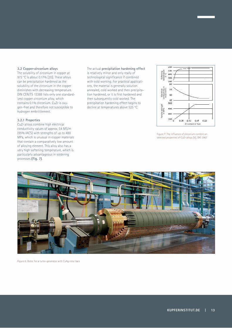
3.1.3 UseThe main applications of copper-silver alloys are: high-strength catenary wires (for high-speed trains); commutator segments and rotor windings in electric motors; transformers and generators that are subjected to high-temperature stresses (Fig. 6); induction heating coils; and electrodes for the resistance welding of aluminium.
3.1.1 PropertiesOne of the benefits of copper-silver alloys compared to pure copper is that the hardness achieved through cold working the material can be maintained even at relatively high temperatures. The softening temperature of CuAg0.10 is around 300 °C.
A further outstanding property of these materials is their relatively high creep rupture strength [4], which is of major significance in applications subjected to mechanical stress at elevated temperatu-res. These beneficial properties are readily apparent in Table 6, which presents data for the alloys CuAg0.04 and CuAg0.10. The high electrical and thermal conductivity of copper is only marginally influenced by the presence of silver (see Fig. 3).
KUPFERINSTITUT.DE | 13
Figure 6: Rotor for a turbo-generator with CuAg rotor bars
Figure 7: The influence of zirconium content on selected properties of CuZr alloys [6], DKI 3967
3.2 Copper-zirconium alloysThe solubility of zirconium in copper at 972 °C is about 0.17% [20]. These alloys can be precipitation hardened as the solubility of the zirconium in the copper diminishes with decreasing temperature. DIN CEN/TS 13388 lists only one standard-ized copper-zirconium alloy, which contains 0.1% zirconium. CuZr is oxy-gen-free and therefore not susceptible to hydrogen embrittlement.
The actual precipitation hardening effect is relatively minor and only really of technological significance if combined with cold working. For practical applicati-ons, the material is generally solution annealed, cold worked and then precipita-tion hardened, or it is first hardened and then subsequently cold worked. The precipitation hardening effect begins to decline at temperatures above 525 °C.
3.2.1 PropertiesCuZr alloys combine high electrical conductivity values of approx. 54 MS/m (95% IACS) with strengths of up to 480 MPa, which is unusual in copper materials that contain a comparatively low amount of alloying element. This alloy also has a very high softening temperature, which is particularly advantageous in soldering processes (Fig. 7).
Sof
teni
ng
tem
pera
ture
in
°C
Ele
ctric
al
cond
uctiv
ity in
m
/(Ω·m
m²)
Tens
ile s
treng
th
in M
Pa
Zr content in %wt.
14 | KUPFERINSTITUT.DE
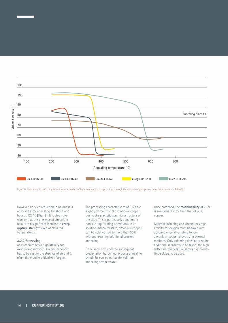
However, no such reduction in hardness is observed after annealing for about one hour at 425 °C (Fig. 8). It is also note-worthy that the presence of zirconium results in a significant increase in creep rupture strength even at elevated temperatures.
The processing characteristics of CuZr are slightly different to those of pure copper due to the precipitation microstructure of the alloy. This is particularly apparent in non-cutting forming operations. In its solution-annealed state, zirconium copper can be cold worked to more than 90% without requiring additional process annealing.
If the alloy is to undergo subsequent precipitation hardening, process annealing should be carried out at the solution annealing temperature.
Once hardened, the machinability of CuZr is somewhat better than that of pure copper.
Material softening and zirconium’s high affinity for oxygen must be taken into account when attempting to join zirconium-copper alloys using thermal methods. Only soldering does not require additional measures to be taken; the high softening temperature allows higher-mel-ting solders to be used.
3.2.2 ProcessingAs zirconium has a high affinity for oxygen and nitrogen, zirconium copper has to be cast in the absence of air and is often done under a blanket of argon.
Figure 8: Improving the softening behaviour of a number of highly conductive copper alloys through the addition of phosphorus, silver and zirconium, DKI 4502
40
50
60
70
80
90
100
110
Vick
ers
hard
ness
[-]
Annealing temperature [°C]
Annealing time: 1 h
100 200 300 400 500 600 700
CuAg0.1P R290 CuZr0.1 R 295CuZr0.1 R262Cu-ETP R250 Cu-HCP R240

KUPFERINSTITUT.DE | 15
If brazing is performed with a filler metal whose melting temperature is above the softening temperature of copper-zirco-nium, brazing times must be kept short to avoid reducing the strength of the hardened parent metal.
Welding is best done using the TIG process and CuAg1 (see DIN EN ISO 24373) as the filler material.
3.3.1 PropertiesThe tensile strength of copper-zinc alloys lies between 220 MPa and 360 MPa depending on the extent to which the alloy has been cold worked. While their softening temperatures are not as high as those of CuAg0.1 or CuZr, temperatures above 250 °C are still required to soften copper-zinc alloys. Their corrosion resistance is similar to that of unalloyed copper. The electrical conductivity of CuZn0.5 is about 83% IACS and thus higher than that of Cu-DHP.
3.3.3 UseDue to the better deep drawing capabilities of copper-zinc alloys, copper strip is now predominantly manufactured using CuZn0.5 rather than Cu-ETP. Copper-zinc alloys are used to manufacture a wide variety of structural components and hollow parts, printed conductors, semiconductor socket, connectors and heat-transfer elements.
3.3.2 ProcessingCopper-zinc alloys can be readily cold worked using techniques such as bending, stamping, beading, drawing and deep drawing. Of particular importance is the much greater ease with which copper-zinc alloys can be deep drawn compared to Cu-DHP, Cu-FRHC and Cu-ETP. Hot working can also be carried out without difficulty at temperatures between 750 °C and 950 °C.
Annealing should not be carried out at too high a temperature, as it can cause formation of a coarse grain structure that impairs cold workability. Copper-zinc alloys can be soldered and brazed using the same fluxes that are used for copper.
It can also be welded using the usual welding techniques. The weldability of copper-zinc alloys is similar to that of unalloyed oxygen-free copper.
3.2.3 UseCopper-zirconium alloy is chosen primarily for applications that require the highest levels of electrical conductivity and a high softening temperature. Examples of such applications include catenary wires, busbars and highly conducting connectors. Because of its high softening temperature and its high resistance to wear, copper-zir-conium alloy is also well suited for commutator segments in large electric motors.
CuZr also finds use as an electrode material for seam welding machines and for rotor windings in highly stressed electric motors.
3.3 Copper-zinc alloysCopper and zinc form homogeneous alloys up to a zinc content of around 37%.
The commercially available low-alloyed materials contain between around 0.5% and 0.9% Zn. Phosphorous is also present, but only in trace amounts.
Due to the deoxidizing effect of the zinc, these alloys are oxygen-free and conse-quently immune to hydrogen embrittle-ment. The alloy CuZn0.5 is standardised in the DIN CEN/TS 13388 compendium.
4. Copper alloys with high or moderate electrical conductivity and medium strength
0.2% yield strength [MPa] Elongation after fracture [A %]Tensile strength [MPa]
16 | KUPFERINSTITUT.DE
Figure 9: Cable harness comprising numerous thin stranded wires
Figure 10: Overhead contact wire for high-speed trains
Material condition
soft annealed
hard drawn (50 %)
hard drawn (80 %)
hard drawn (98 %)
80
410
510
640
270
450
550
695
50
5
4
2
Table 7: Strength parameters for wires made from CuMg0.7 [8]
Depending on the temper condition of the metal, the tensile strength of pure copper ranges from around 200 MPa to more than 400 MPa, which may be insufficient for some applications. The tensile strength of copper can be increased by the addition of alloying elements such as magnesium, chromium and iron. These higher tensile strength copper alloys are required, for example, in the manufacture of the highly stressed electrodes used in resistance welding.
The presence of magnesium increases the softening temperature to about 350 °C, while the reduction in electrical conducti-vity is slightly greater than that caused by silver (see Fig. 3).
4.1.2 ProcessingThe large freezing range exhibited by copper-magnesium alloys and their propensity to form magnesium oxide at the surface creates a number of difficulties for smelting and casting operations, though these problems can be overcome by metallurgical adjustments and adapting the casting procedures used.
Like unalloyed copper, copper-magnesium alloys can be readily hot and cold worked. Their higher recrystallisation temperatures compared to pure copper means that soft annealing is done at around 650 °C. The machinability, solderability and brazea-bility of copper-magnesium alloys are roughly similar to those of unalloyed copper.
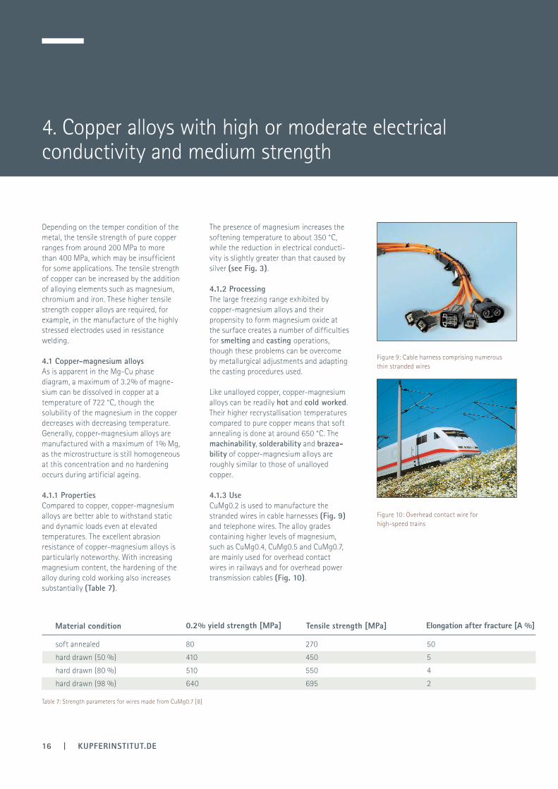
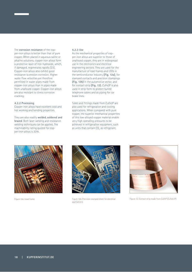
4.1.3 UseCuMg0.2 is used to manufacture the stranded wires in cable harnesses (Fig. 9) and telephone wires. The alloy grades containing higher levels of magnesium, such as CuMg0.4, CuMg0.5 and CuMg0.7, are mainly used for overhead contact wires in railways and for overhead power transmission cables (Fig. 10).
4.1 Copper-magnesium alloysAs is apparent in the Mg-Cu phase diagram, a maximum of 3.2% of magne-sium can be dissolved in copper at a temperature of 722 °C, though the solubility of the magnesium in the copper decreases with decreasing temperature. Generally, copper-magnesium alloys are manufactured with a maximum of 1% Mg, as the microstructure is still homogeneous at this concentration and no hardening occurs during artificial ageing.
4.1.1 PropertiesCompared to copper, copper-magnesium alloys are better able to withstand static and dynamic loads even at elevated temperatures. The excellent abrasion resistance of copper-magnesium alloys is particularly noteworthy. With increasing magnesium content, the hardening of the alloy during cold working also increases substantially (Table 7).

4. Copper alloys with high or moderate electrical conductivity and medium strength
KUPFERINSTITUT.DE | 17
Figure 11a: The influence of iron on the softening behaviour of copper (CuFe0.1P R360-430)
70
80
90
100
110
120
130
140
RT 400°C 425°C 450°C
Har
dnes
s [H
V10]
Temperature [°C] (holding time: 30 min.)
500°C
400°C
450°C
Figure 11b: The influence of iron on the softening behaviour of copper (CuFe2P R470)
100
90
80
70
110
120
130
140
150
160
Vick
ers
hard
ness
[-]
0 10 20 30 40 50 60Holding time in minutes
4.2 Copper-iron alloysThe solubility of iron in copper at 1095 °C is about 4.1% [20]. As the solubility of the iron decreases with falling temperature, this alloy system can, in principle, undergo precipitation hardening. However, the increase in strength associated with the precipitation is negligible and is of little technical value. The properties of copper-iron alloys that offer technical benefits are the increased electrical conductivity and the higher recrystallisa-tion temperature.
The alloys CuFe2P and CuFe0.1P are readily available commercially. CuFe2P is included in the DIN EN 1654 and DIN EN 1758 standards. In the UNS classification scheme (Unified Numbering System), CuFe0.1P is designated as C19210.
4.2.1 PropertiesIron-copper alloy is characterized by its high thermal and electrical conductivity. Depending on the composition and the heat treatment regime applied, thermal conductivities of up to 350 W/(mK) and electrical conductivities up to 90% IACS are attainable.
Cold-worked CuFe2P can achieve a tensile strength in excess of 500 MPa and an electrical conductivity of 74% IACS. The softening temperature lies in the range 400–500 °C depending on the initial condition of the alloy.
Figures 11a and 11b show the softening behaviour of the alloys CuFe0.1P and CuFe2P.
18 | KUPFERINSTITUT.DE
Figure 12a: Lead frame Figure 12b: Precision stamped sheet for electrical applications
Figure 13: Contact strip made from CuFeP (CuFe0.1P)
The corrosion resistance of the cop-per-iron alloys is better than that of pure copper. When placed in aqueous saline or alkaline solutions, copper-iron alloys form a protective layer of iron hydroxide, which, if damaged, regenerates rapidly [23]. Copper-iron alloys also exhibit good resistance to erosion corrosion. Higher water flow velocities are therefore permitted in water pipes made from copper-iron alloys than in pipes made from unalloyed copper. Copper-iron alloys are also resistant to stress corrosion cracking.
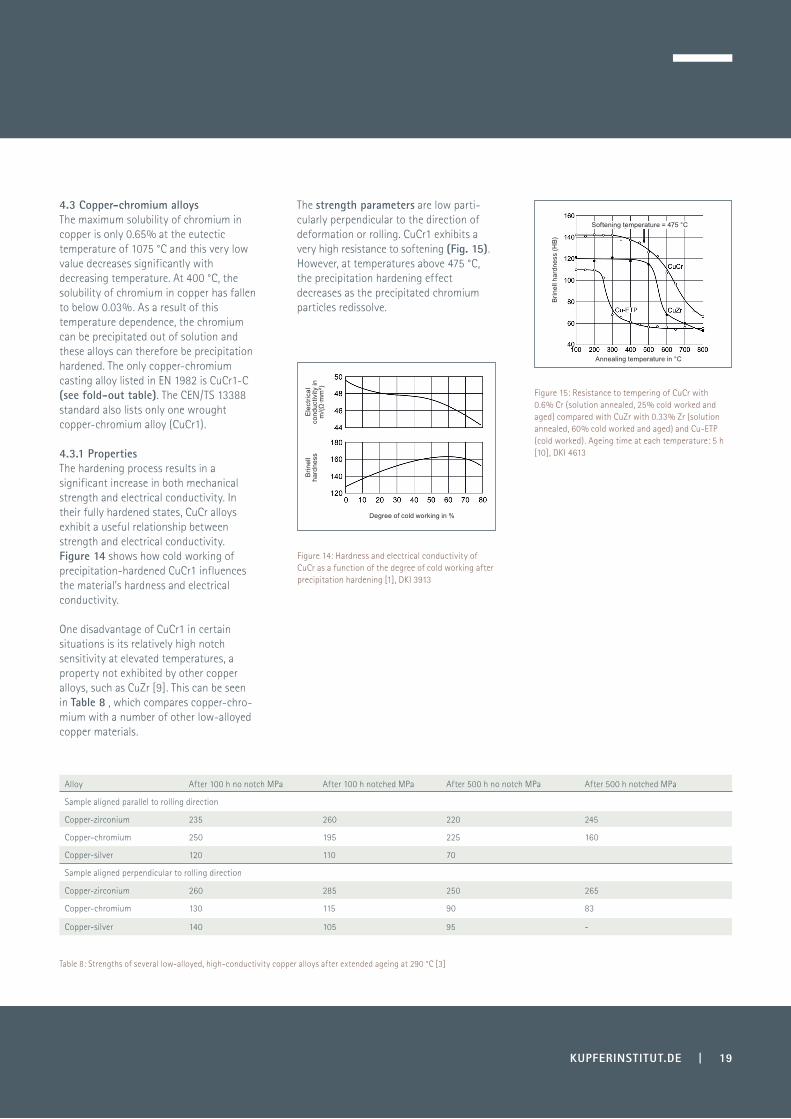
4.2.3 UseAs the mechanical properties of cop-per-iron alloys are superior to those of unalloyed copper, they are in widespread use in the electronics and electrical engineering sectors. They are used for the manufacture of lead frames and LEDs in the semiconductor industry (Fig. 12a), for stamped contacts and precision stampings (Fig. 12b) in the automotive sector, and for contact strip (Fig. 13). CuFe2P is also used in strip form to protect buried telephone cables and as piping for car brake lines.
Tubes and fittings made from CuFe2P are also used for refrigeration and cooling applications. When compared with pure copper, the superior mechanical properties of this low-alloyed copper material enable very high operating pressures to be achieved in refrigeration equipment, such as units that contain CO2 as refrigerant.
4.2.2 ProcessingCopper-iron alloys have excellent cold and hot working and bending properties.
They are also readily welded, soldered and brazed. Both laser welding and resistance welding techniques can be applied. The machinability rating quoted for cop-per-iron alloys is 20%.
KUPFERINSTITUT.DE | 19
Figure 14: Hardness and electrical conductivity of CuCr as a function of the degree of cold working after precipitation hardening [1], DKI 3913
Figure 15: Resistance to tempering of CuCr with 0.6% Cr (solution annealed, 25% cold worked and aged) compared with CuZr with 0.33% Zr (solution annealed, 60% cold worked and aged) and Cu-ETP (cold worked). Ageing time at each temperature: 5 h [10], DKI 4613
Table 8: Strengths of several low-alloyed, high-conductivity copper alloys after extended ageing at 290 °C [3]
Alloy After 100 h no notch MPa After 100 h notched MPa After 500 h no notch MPa After 500 h notched MPa
Sample aligned parallel to rolling direction
Copper-zirconium 235 260 220 245
Copper-chromium 250 195 225 160
Copper-silver 120 110 70
Sample aligned perpendicular to rolling direction
Copper-zirconium 260 285 250 265
Copper-chromium 130 115 90 83
Copper-silver 140 105 95 -
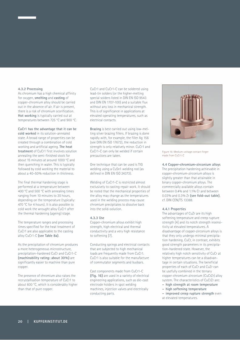
4.3 Copper-chromium alloysThe maximum solubility of chromium in copper is only 0.65% at the eutectic temperature of 1075 °C and this very low value decreases significantly with decreasing temperature. At 400 °C, the solubility of chromium in copper has fallen to below 0.03%. As a result of this temperature dependence, the chromium can be precipitated out of solution and these alloys can therefore be precipitation hardened. The only copper-chromium casting alloy listed in EN 1982 is CuCr1-C (see fold-out table). The CEN/TS 13388 standard also lists only one wrought copper-chromium alloy (CuCr1).
The strength parameters are low parti- cularly perpendicular to the direction of deformation or rolling. CuCr1 exhibits a very high resistance to softening (Fig. 15). However, at temperatures above 475 °C, the precipitation hardening effect decreases as the precipitated chromium particles redissolve.
4.3.1 PropertiesThe hardening process results in a significant increase in both mechanical strength and electrical conductivity. In their fully hardened states, CuCr alloys exhibit a useful relationship between strength and electrical conductivity. Figure 14 shows how cold working of precipitation-hardened CuCr1 influences the material’s hardness and electrical conductivity.
One disadvantage of CuCr1 in certain situations is its relatively high notch sensitivity at elevated temperatures, a property not exhibited by other copper alloys, such as CuZr [9]. This can be seen in Table 8 , which compares copper-chro-mium with a number of other low-alloyed copper materials.
Ele
ctric
al
cond
uctiv
ity in
m
/(Ω·m
m²)
Brin
ell h
ardn
ess
(HB)
Annealing temperature in °C
Softening temperature = 475 °C
Brin
ell
hard
ness
Degree of cold working in %
20 | KUPFERINSTITUT.DE
Figure 16: Medium-voltage contact finger made from CuCr1-C
4.3.2 ProcessingAs chromium has a high chemical affinity for oxygen, smelting and casting of copper-chromium alloy should be carried out in the absence of air. If air is present, there is a risk of chromium scorification. Hot working is typically carried out at temperatures between 725 °C and 900 °C.
CuCr1 and CuCr1-C can be soldered using lead-tin solders (or the higher-melting special solders listed in DIN EN ISO 9543 and DIN EN 1707-100) and a suitable flux without any loss in mechanical strength. This is of significance in applications at elevated operating temperatures, such as electrical contacts.
4.4 Copper-chromium-zirconium alloysThe precipitation hardening achievable in copper-chromium-zirconium alloys is slightly greater than that attainable in binary copper-chromium alloys. The commercially available alloys contain between 0.4% and 1.1% Cr and between 0.03% and 0.3% Zr (see fold-out table), cf. DIN CEN/TS 13388.
4.4.1 PropertiesThe advantages of CuZr are its high softening temperature and creep rupture strength [4] and its notch strength insensi-tivity at elevated temperatures. A disadvantage of copper-zirconium alloys is that they only undergo minimal precipita-tion hardening. CuCr, in contrast, exhibits good strength parameters in its precipita-tion-hardened state. However, the relatively high notch sensitivity of CuCr at higher temperatures can be a disadvan-tage in certain situations. The beneficial properties of each of CuCr and CuZr can be usefully combined in the ternary copper-chromium-zirconium (CuCrZr) alloy system. The characteristics of CuCrZr are:- high strength at room temperature- high softening temperature - improved creep rupture strength even at elevated temperatures.
Brazing is best carried out using low-mel-ting silver brazing fillers. If brazing is done rapidly with, for example, the filler Ag 156 (see DIN EN ISO 17672), the reduction in strength is only relatively minor. CuCr1 and CuCr1-C can only be welded if certain precautions are taken.
One technique that can be used is TIG welding using a CuSn1 welding rod (as defined in DIN EN ISO 24373).
CuCr1 has the advantage that it can be cold worked in its solution-annealed state. A broad range of properties can be created through a combination of cold working and artificial ageing. The heat treatment of CuCr1 first involves solution annealing the semi-finished stock for about 15 minutes at around 1000 °C and then quenching in water. This is typically followed by cold working the material to about a 40–50% reduction in thickness.
The final thermal hardening stage is performed at a temperature between 400 °C and 500 °C with annealing times ranging from 10 minutes to 20 hours, depending on the temperature (typically: 470 °C for 4 hours). It is also possible to cold work the wrought alloy CuCr1 after the thermal hardening (ageing) stage.
Welding of CuCr1-C is restricted almost exclusively to casting repair work. It should be noted that the mechanical properties of the alloy may change as the temperatures used in the welding process may cause chromium precipitates to dissolve back into the solid-solution.
4.3.3 UseCopper-chromium alloys exhibit high strength, high electrical and thermal conductivity and a very high resistance to softening [7].
Conducting springs and electrical contacts that are subjected to high mechanical loads are frequently made from CuCr1. CuCr1 is also suitable for the manufacture of commutator segments and busbars.
Cast components made from CuCr1-C (Fig. 16) are used in a variety of electrical engineering applications, such as die-cast electrode holders in spot welding machines, injection valves and electrically conducting parts.
The temperature ranges and processing times specified for the heat treatment of CuCr1 are also applicable to the casting alloy CuCr1-C (see Table 8a).
As the precipitation of chromium produces a more heterogeneous microstructure, precipitation-hardened CuCr and CuCr1-C (machinability rating: about 30%) are significantly easier to machine than pure copper.
The presence of chromium also raises the recrystallisation temperature of CuCr1 to about 600 °C, which is considerably higher than that of pure copper.

KUPFERINSTITUT.DE | 21
The ternary alloy CuCr1Zr is superior to both of the binary alloys CuCr and CuZr in all three of these properties. This behaviour is explained by the increased solubility of chromium in copper at high temperatures due to the presence of zirconium [7]. When subjected to creep stress, CuCr1Zr also exhibits a certain propensity to brittleness at temperatures above about 100 °C as a result of the formation of pores at the grain boundaries [4]. The precipitation hardening behaviour of CuCr1Zr is roughly equivalent to that of CuCr1.
Although Brinell hardness values above 160 HB are almost impossible to achieve in CuCr1, no matter how skilfully cold working and precipitation hardening are combined, they can be attained in CuCr1Zr (see Fig. 15). The other strength parameters of CuCr1Zr are also more favourable than those of the binary alloy CuCr1, particularly at higher temperatures (see Table 9).However, at temperatures above 500 °C, the precipitation hardening effect begins to diminish (Fig. 17). Figure 18 shows the creep behaviour of CuCr1Zr compared with two copper-zirconium alloys. Of the alloys examined, CuCr1Zr shows the most favourable properties.
The physical properties of CuCr1Zr correspond approximately to those of CuCr1 (see fold-out table). The electrical conductivity of the alloy in its fully hardened state is in the range 78–86% IACS.
Figure 17: Tempering curve for CuCrZr rods with an initial hardness of 170 HV10 (condition: solution annealed, cold worked, hardened); annealing time: 30 min
Figure 18: Creep behaviour of CuCr1Zr compared with CuZr, test temperature: 230 °C (250 °C for the 1500 h curve) [1], DKI 3970
Table 9: Comparison of the strength parameters of CuCrZr and CuCr at different temperatures, S = smooth specimen, N = notched specimen [3]
AlloyType of specimen 20°C 200°C 300°C
Rm[MPa] A [%] Rm[MPa] A [%] Rm[MPa] A [%]
CuCr1Zr rodDiameter: 9.5 mm
S 550 22 465 21 415 19
N 600 20 490 17 450 13
CuCr1 strip6 x 76 mm
S 510 17 420 10 280 7
N 445 13 415 10 355 7
Symbol and material number
Cu-C (CC040A)
‘Type A’
CuCr1-C (CC140C)
‘Artificially aged’
40 150 25 40
Table 8a: Comparison of strength parameters of Cu-C and CuCr1-C
0.2% yield strength Rp0.2 (MPa)
Tensile strength Rm (MPa)
Elongation after fracture A5%
Brinell hardness HB
250 350 10 110
Vic
kers
har
dnes
s (H
V10)
Tempering temperature in °C Time under load in hours
in air smeltedin vacuum and cast
Cre
ep e
long
atio
n in
%
22 | KUPFERINSTITUT.DE
4.4.2 ProcessingThe cold workability of CuCr1Zr is particularly good when the alloy is in its soft annealed state. Hot working is best carried out between 850 °C and 950 °C. The machinability of the solution-annea-led alloy is similar to that of unalloyed copper (machinability rating: 20%), but is significantly improved when the alloy is in its hardened state (machinability rating: 30%).
Like pure copper, CuCr1Zr can be readily soldered without any real loss in the strength of the base material. However, the material can only be brazed or welded under special conditions. Electron beam welding and laser welding can be used.
Copper and nickel are completely soluble in both the molten and solid states. As the amount of phosphorus in the alloy increases, the solubility of the resulting nickel phosphides decreases significantly in the solid solution. The solubility of the nickel phosphides in the solid solution is much smaller than the solubility observed in other low-alloy, precipitation-hardena-ble copper alloy systems, such as Cu-Ni-Si or Cu-Be, and the electrical and thermal conductivity observed in hardened Cu-Ni-P alloys is correspondingly greater.
4.5.1 PropertiesThe copper-nickel-phosphorus alloy system combines high electrical conductivity and high strength. The formation of fine nickel phosphide precipitates and the purity of the copper are critical parameters in controlling the microstructure, and thus the strength and conductivity of the alloy. Because of the high strengths (550–700 MPa) that can be achieved in the precipitation-hardened state (see fold-out table) and the relatively good electrical conductivity of between 50% and 65% IACS, these alloys are frequently used for the production of electrical contacts. The optimum parameters for the precipitation hardening process depend on the preceding cold working stage as this influences the precipitation kinetics.
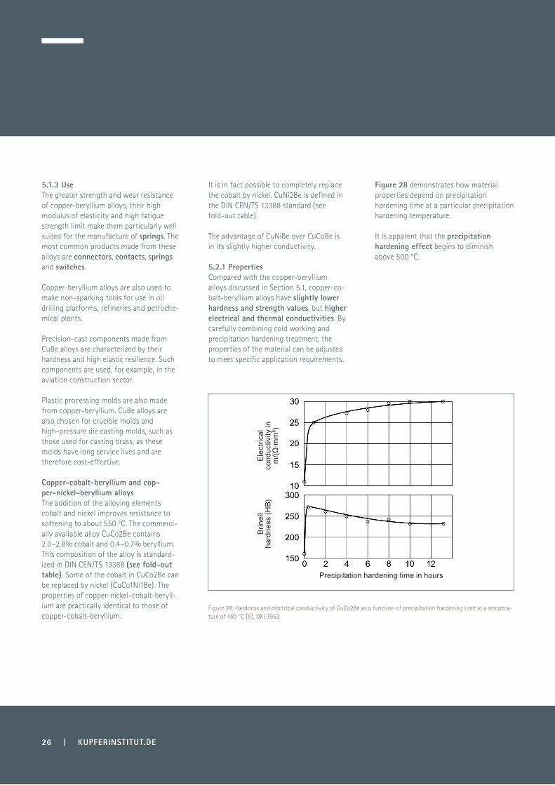
As a result of the stress relief that accompanies artificial ageing, the elongation after fracture in these alloys can be increased from 3% to 20%. Hardening is carried out most efficiently at temperatures in the range 380–420 °C. Cu-Ni-P also exhibits good stress-relaxa-tion behaviour at high operating temperatures (Fig. 23).
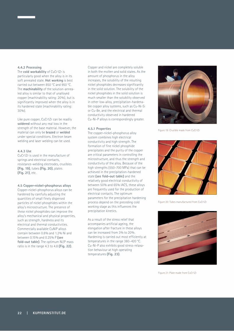
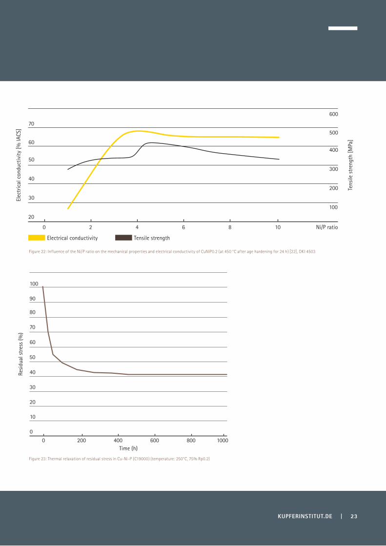
4.4.3 UseCuCr1Zr is used in the manufacture of springs and electrical contacts, resistance-welding electrodes, crucibles (Fig. 19), tubes (Fig. 20), plates (Fig. 21), etc.
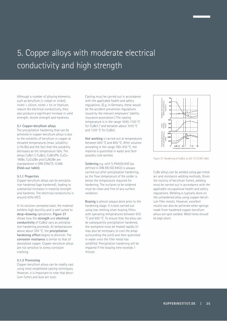
4.5 Copper-nickel-phosphorus alloysCopper-nickel-phosphorus alloys can be hardened by carefully adjusting the quantities of small finely dispersed particles of nickel phosphides within the alloy’s microstructure. The presence of these nickel phosphides can improve the alloy’s mechanical and physical properties, such as strength, hardness and its electrical and thermal conductivities. Commercially available CuNiP alloys contain between 0.8% and 1.2% Ni and between 0.15% and 0.25% P (see fold-out table). The optimum Ni/P mass ratio is in the range 4.3 to 4.8 (Fig. 22).
Figure 19: Crucible made from CuCr1Zr
Figure 20: Tubes manufactured from CuCr1Zr
Figure 21: Plate made from CuCr1Zr
KUPFERINSTITUT.DE | 23
Figure 22: Influence of the Ni/P ratio on the mechanical properties and electrical conductivity of CuNiP0.2 (at 450 °C after age hardening for 24 h) [22], DKI 4503
20
30
40
50
60
70
Elec
tric
al c
ondu
ctiv
ity [%
IACS
]
0 2 4 6 8 10 Ni/P ratio
100
200
300
400
500
600
Electrical conductivity Tensile strength
Tens
ile s
tren
gth
[MPa
]
Resi
dual
str
ess
(%)
30
20
10
0
40
50
60
70
80
90
100
0 200 400 600 800 1000Time (h)
Figure 23: Thermal relaxation of residual stress in Cu-Ni-P (C19000) (temperature: 250°C, 75% Rp0.2)

24 | KUPFERINSTITUT.DE
4.5.2 ProcessingSolution-annealed Cu-Ni-P shows excellent cold workability. The Cu-Ni-P alloy system has the following features:
To avoid too great a reduction in electrical conductivity, low-alloyed CuSn alloys generally contain up to 0.6% tin and no more than 0.01% of phosphorus. There are also oxygen-containing CuSn alloys in that form when the oxygen in the melt reacts to produce tin oxide.
4.6.1 PropertiesCompared with pure copper, low-alloyed copper-tin materials exhibit slightly greater strength while retaining good electrical conductivity. With increasing tin content, the hardening of the alloy during cold working also increases (Fig. 25). The softening temperature also increases to about 330 °C (Fig. 26). The reduction in the electrical conductivity of copper caused by the presence of tin is slightly greater than the reduction caused by magnesium (see Fig. 3).
4.6.2 ProcessingCopper-tin alloys are easy to cast and have excellent hot and cold working properties. These alloys can be drawn to make fine wire. Annealing is normally performed at 400 °C.
4.6.3 UseA typical use of CuSn0.15 is in the manufacture of lead frames (DIN EN 1758), while CuSn0.3 is chosen for the fine-gauge stranded wire in cable harnesses and for catenary wires.
4.5.3 UseCu-Ni-P alloys are used to manufacture connector components, such as the contact pins, push-on terminal strips and conducting springs used in electronic and electrical applications. Strips of Cu-Ni-P alloys are used in the production of springs, clips, contact supports and connectors. Rods and hollow tubing are processed to make welding pliers, electrode holders, earth (ground) clamps and seam-welding rollers. These products are used in the IT, aviation, telecommuni-cations and automotive industries.
4.6 Copper-tin alloysCopper-tin alloys belong to the oldest known copper-based materials used for technical applications. Even small quantities of the alloying element tin will improve softening behaviour compared to that of pure copper. Provided that the amount of tin does not exceed 1%, the segregation behaviour observed in high-alloyed bronzes is not particularly pronounced. To ensure deoxidation of the copper-tin melt, a small quantity of phosphorus can be added to the melt.
· Phosphorus has a deoxidizing effect in the melt and leads to the formation of nickel phosphide precipitates during age hardening.· Hot working and solution annealing are carried out at temperatures in the range 700–800 °C.· The machinability of these alloys in their solution-annealed state is similar to that of unalloyed copper. To improve machinability, CuNi1P can be alloyed with up to 1% lead (Fig. 24).
Figure 26: softening benaviour of CuSn0.15 [25], DKI 4506
Figure 24: Microstructure of the alloy CuNi1P0.2Pb1 (C19160) in its solution-annealed state
Tens
ile s
treng
th in
MP
a
Brin
ell h
ardn
ess
(HB)
0.2%
yie
ld s
treng
th in
MP
a
Tin content in %wt.
Vic
kers
har
dnes
s H
V
Temperature in °C
Degree of working: 60%
unworked
unworked
unworked
unworked
50% cold worked
50% cold worked
50% cold worked
50% cold worked
Elo
ngat
ion
afte
r fra
ctur
e in
%
Figure 25: Hardening behaviour of copper-tin wrought alloys as a function of tin content [24], DKI 1557
KUPFERINSTITUT.DE | 25
5. Copper alloys with moderate electrical conductivity and high strength
Figure 27: Hardening of CuBe2 at 325 °C [1] DKI 3962
Although a number of alloying elements, such as beryllium (+ cobalt or nickel), nickel + silicon, nickel + tin or titanium, reduce the electrical conductivity, they also produce a significant increase in yield strength, tensile strength and hardness.
Casting must be carried out in accordance with the applicable health and safety regulations. (E.g. in Germany, these would be the accident prevention regulations issued by the relevant employers’ liability insurance association.) The casting temperature is in the range 1040–1120 °C for CuBe1.7 and between about 1010 °C and 1120 °C for CuBe2.
Hot working is carried out at temperatures between 600 °C and 800 °C. After solution annealing in the range 780–810 °C, the material is quenched in water and then possibly cold worked.
Soldering e.g. with S-Pb50Sn50E (as defined in DIN EN ISO 9453) is always carried out after precipitation hardening, as the flow temperature of the solder is below the temperature required for hardening. The surfaces to be soldered must be clean and free of any surface oxidation.
Brazing is almost always done prior to the hardening stage. It is best carried out using low-melting silver brazing fillers with operating temperatures between 610 °C and 650 °C. To ensure that the alloy can be subsequently precipitation hardened, the workpiece must be heated rapidly (it may also be necessary to cool the areas surrounding the joint) and then quenched in water once the filler metal has solidified. Precipitation hardening will be impaired if the brazing time exceeds 1 minute.
CuBe alloys can be welded using gas metal arc and resistance welding methods. Given the toxicity of beryllium fumes, welding must be carried out in accordance with the applicable occupational health and safety regulations. Welding is typically done on the unhardened alloy using copper-beryll-ium filler metals. However, excellent results can also be achieved when springs made from hardened copper-beryllium alloys are spot welded. Weld times should be kept short.
5.1 Copper-beryllium alloysThe precipitation hardening that can be achieved in copper-beryllium alloys is due to the solubility of beryllium in copper at elevated temperatures (max. solubility: 2.1% Be) and the fact that this solubility decreases as the temperature falls. The alloys CuBe1.7, CuBe2, CuBe2Pb, CuCo-1NiBe, CuCo2Be and CuNi2Be are standardized in DIN CEN/TS 13388 (fold-out table).
5.1.1 PropertiesCopper-beryllium alloys can be precipita-tion hardened (age hardened), leading to substantial increases in material strength and hardness. The electrical conductivity is around 43% IACS.
In its solution-annealed state, the material exhibits high ductility and is well suited to deep-drawing operations. Figure 27 shows how the strength and electrical conductivity of CuBe2 vary as precipita-tion hardening proceeds. At temperatures above about 350 °C, the precipitation hardening effect begins to diminish. The corrosion resistance is similar to that of deoxidized copper. Copper-beryllium alloys are not sensitive to stress corrosion cracking.
5.1.2 ProcessingCopper-beryllium alloys can be readily cast using most established casting techniques. However, it is important to note that beryl-lium fumes and dust are toxic.
Elo
ngat
ion
afte
r fra
ctur
e (A
) in
%
Ele
ctric
al c
ondu
ctiv
ity in
m
/(Ω·m
m²)
Vic
kers
ha
rdne
ss
(HV1
0)
Precipitation hardening time in hours
Tens
ile s
treng
th (R
m) a
nd
0.2%
yie
ld s
treng
th (R
p0.2)
in M
Pa
26 | KUPFERINSTITUT.DE
5.1.3 UseThe greater strength and wear resistance of copper-beryllium alloys, their high modulus of elasticity and high fatigue strength limit make them particularly well suited for the manufacture of springs. The most common products made from these alloys are connectors, contacts, springs and switches.
It is in fact possible to completely replace the cobalt by nickel. CuNi2Be is defined in the DIN CEN/TS 13388 standard (see fold-out table).
The advantage of CuNiBe over CuCoBe is in its slightly higher conductivity.
Figure 28 demonstrates how material properties depend on precipitation hardening time at a particular precipitation hardening temperature.
It is apparent that the precipitation hardening effect begins to diminish above 500 °C.
5.2.1 PropertiesCompared with the copper-beryllium alloys discussed in Section 5.1, copper-co-balt-beryllium alloys have slightly lower hardness and strength values, but higher electrical and thermal conductivities. By carefully combining cold working and precipitation hardening treatment, the properties of the material can be adjusted to meet specific application requirements.
Copper-beryllium alloys are also used to make non-sparking tools for use in oil drilling platforms, refineries and petroche-mical plants.
Precision-cast components made from CuBe alloys are characterized by their hardness and high elastic resilience. Such components are used, for example, in the aviation construction sector.
Plastic processing molds are also made from copper-beryllium. CuBe alloys are also chosen for crucible molds and high-pressure die casting molds, such as those used for casting brass, as these molds have long service lives and are therefore cost-effective.
Copper-cobalt-beryllium and cop-per-nickel-beryllium alloysThe addition of the alloying elements cobalt and nickel improves resistance to softening to about 550 °C. The commerci-ally available alloy CuCo2Be contains 2.0–2.8% cobalt and 0.4–0.7% beryllium. This composition of the alloy is standard-ized in DIN CEN/TS 13388 (see fold-out table). Some of the cobalt in CuCo2Be can be replaced by nickel (CuCo1Ni1Be). The properties of copper-nickel-cobalt-beryll-ium are practically identical to those of copper-cobalt-beryllium.
Figure 28: Hardness and electrical conductivity of CuCo2Be as a function of precipitation hardening time at a tempera-ture of 480 °C [8], DKI 3963
Ele
ctric
al
cond
uctiv
ity in
m
/(Ω·m
m²)
Brin
ell
hard
ness
(HB)
Precipitation hardening time in hours
5.2.2 ProcessingCuCo2Be alloy can be cast using most established casting techniques. However, as beryllium fumes are toxic, there must be adequate ventilation when smelting, casting or welding this alloy and the work must be carried out in accordance with the applicable health and safety regulations. Casting is done at temperatures between 1100 °C and 1180 °C.
Hot working is carried out at temperatu-res between 750 °C and 950 °C. The material can be readily cold worked once it has been solution annealed. Solution annealing is performed in the temperature range 920–960 °C, after which the material is water-quenched and may then also be cold worked. Any intermediate process annealing steps should be carried out as a full solution annealing procedure. The alloy is usually machined in its cold worked or precipitation-hardened state.
CuCo2Be can be readily soldered and does not result in any deterioration in the properties of the hardened material. If the material needs to be brazed without suffering too great a loss in hardness, low-melting silver brazing fillers and short brazing times should be used. Like pure copper, CuCo2Be can be welded but it leads to a loss of strength.
5.2.3 UseCuCo2Be is used to make the highly stressed, conducting springs in relays and switches and to manufacture semi-con-ductor heat sinks.
The alloy is also used for resistance-wel-ding electrodes. Due to its combination of superior hardness and good thermal conductivity, CuCo2Be is the most suitable material for the nozzles used in the oxyfuel cutting of steel.
One particularly interesting application of CuCo2Be is its use in the manufacture of membrane components for aviation instruments. CuCo2Be is chosen for such applications because of its corrosion resistance, durability and good workability in its solution-annealed state, as well as its excellent strength in its precipitation-har-dened state and its outstanding spring properties. CuNi2Be is used to make casting molds because of its high fatigue strength and wear resistance.
5.3 Copper-nickel-silicon alloysThe high solubility of silicon in copper can be significantly reduced by the addition of nickel and the solubility decreases further with falling temperature. The temperatu-re-dependent solubility of the intermetallic compounds Ni2Si, Ni5Si2 (or Ni31Si12) means that copper-nickel-silicon alloys can be precipitation hardened. The crystal structures of the silicides are semi-coher-ent or incoherent with the matrix. The three alloys CuNi1,5Si, CuNi2Si and CuNi3Si are standardized in DIN CEN/TS 13388 (see fold-out table).
5.3.1 PropertiesCopper-nickel-silicon alloys exhibit high tensile strengths (up to about 900 MPa for some thin Cu-Ni-Si sheets), electrical conductivities of up to 50% IACS, good corrosion resistance and good workability. The excellent thermal stability of the higher nickel alloys make them well suited for the manufacture of springs elements that will be used at temperatures above 150 °C. Adding small quantities of magnesium improves resistance to stress relaxation.
Partial substitution of nickel by cobalt can increase mechanical strength by up to 100 MPa.
Age-hardened Cu-Ni-Si alloys are highly resistant to stress corrosion cracking. These alloys are particularly wear resistant due to their high levels of hardness.
KUPFERINSTITUT.DE | 27
28 | KUPFERINSTITUT.DE
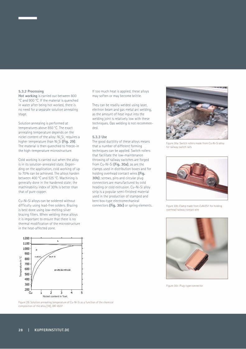
Figure 30a: Switch rollers made from Cu-Ni-Si alloy for railway switch rails
Figure 30b: Clamp made from CuNi2Si1 for holding overhead railway contact wire
Figure 30c: Plug-type connector
Figure 29: Solution annealing temperature of Cu-Ni-Si as a function of the chemical composition of the alloy [18], DKI 4507
5.3.2 ProcessingHot working is carried out between 800 °C and 900 °C. If the material is quenched in water after being hot worked, there is no need for a separate solution annealing stage.
Solution annealing is performed at temperatures above 850 °C. The exact annealing temperature depends on the nickel content of the alloy: Ni5Si2 requires a higher temperature than Ni2Si (Fig. 29). The material is then quenched to freeze-in the high-temperature microstructure.
If too much heat is applied, these alloys may soften or may become brittle.
They can be readily welded using laser, electron beam and gas metal arc welding, as the amount of heat input into the welding joint is relatively low with these techniques. Gas welding is not recommen-ded.
5.3.3 UseThe good ductility of these alloys means that a number of different forming techniques can be applied. Switch rollers that facilitate the low-maintenance throwing of railway switches are forged from Cu-Ni-Si (Fig. 30a), as are the clamps used in distribution boxes and for holding overhead contact wires (Fig. 30b); screws, pins and circular plug connectors are manufactured by cold heading or cold extrusion. Cu-Ni-Si alloy strip is a popular semi-finished material used in the production of stamped and bent box-type electromechanical connectors (Fig. 30c) or spring elements.
Cold working is carried out when the alloy is in its solution-annealed state. Depen-ding on the application, cold working of up to 70% can be achieved. The alloys harden between 400 °C and 525 °C. Machining is generally done in the hardened state; the machinability index of 30% is better than that of pure copper.
Cu-Ni-Si alloys can be soldered without difficulty using lead-free solders. Brazing is best done using low-melting silver brazing fillers. When welding these alloys it is important to ensure that there is no thermal modification of the microstructure in the heat-affected zone.
Tem
pera
ture
in °
C
Nickel content in %wt.

KUPFERINSTITUT.DE | 29
Copper-nickel-silicon alloys are chosen for some of these applications, because they can be bent to produce sharp-edged structures. They are also able to withstand high mechanical, electrical and thermal loads. In the electronics sector, these alloys are used to make lead frames, which act as electrical connectors and passive cooling elements for semiconductor devices. In some cases, the strips used in the manufacture of lead frames are silver plated.
5.4.1 PropertiesIn addition to their good conductivity and strength parameters these alloys also exhibit significant resistance to stress relaxation.
These materials are therefore particularly well suited for high-temperature applicati-ons (above 150 °C). Depending on the specific Cu-Ni-Sn alloy used, cold working of small workpieces can increase mechani-cal strength to more than 540 MPa while retaining good material flexibility. Softening begins at 400 °C to 450 °C. These alloys are particularly suitable for manufacturing small electrical and electronic components. They are resistant to stress corrosion cracking.
5.4.2 ProcessingCu-Ni-Sn alloys are well suited to cold working. They can be readily welded and brazed The surface can be electroplated (with tin, nickel, silver or gold) or hot-dipped tin plated.
5.4.3 UseCopper-nickel-tin alloys are used for electrical connectors and contacts (e.g. in the automotive sector), precision stampings, central electrical control units, relays, switches and lead frames.
Their good self-lubricating properties make them well suited as materials for highly stressed bushings, thrust washers and slideways. The excellent corrosion resistance of Cu-Ni-Si alloys has led to their frequent use for marine construction applications, including inboard marine motors and engines, and for chemical and process plant equipment.
This class of copper alloys is also chosen for high-strength, corrosion-resistant nuts and bolts, for wire cables in electric overhead line systems, for roller bearing cages and valve guides.
5.4 Copper-nickel-tin alloysWhen alloying the copper-nickel-tin system, added phosphorus converts some of the nickel to nickel phosphide precipita-tes. The precipitated particles are then finely dispersed throughout the micros-tructure by a carefully controlled sequence of rolling and annealing operations.
As a result, these alloys offer an excellent combination of electrical conductivity and material strength. The alloys are not currently standardized in Europe, but some are standardized in the USA in ASTM B 422 and B 888 (e.g. CuNi1Sn0.9, which appears as C19025).
30 | KUPFERINSTITUT.DE
This final section presents a number of materials in the group of low-alloyed copper alloys whose electrical conductivity is of secondary relevance but that have established themselves as important materials in the plant and process equipment industry due to their high corrosion resistance and good processabi-lity (e.g. weldability). These alloys include elements such as arsenic, manganese, or silicon + manganese.
Materials in this group can be readily soldered and brazed and exhibit excellent welding properties as they are essentially oxygen-free and have low thermal conductivities [11].
6.1.3 UseThe thermal stability and corrosion resistance of Cu-Mn alloys make them particularly suitable for plant equipment used in the chemical and general process industries, and for the manufacture of marine boilers.
Copper-silicon and copper- silicon-manganese alloysThe maximum solubility of silicon in copper is 5.3% at 842 °C and the solubility decreases with decreasing temperature [7]. The engineering alloys with a maximum silicon content of 3.6% exhibit a homoge-neous microstructure. These alloys typically contain between 1.8% to 3.6% Si and 0.3% to 1.3% Mn. The presence of manganese has only a minor influence on the solubility of the silicon in copper. The alloys CuSi1 and CuSi3Mn are standardized in DIN CEN/TS 13388 (see fold-out table).
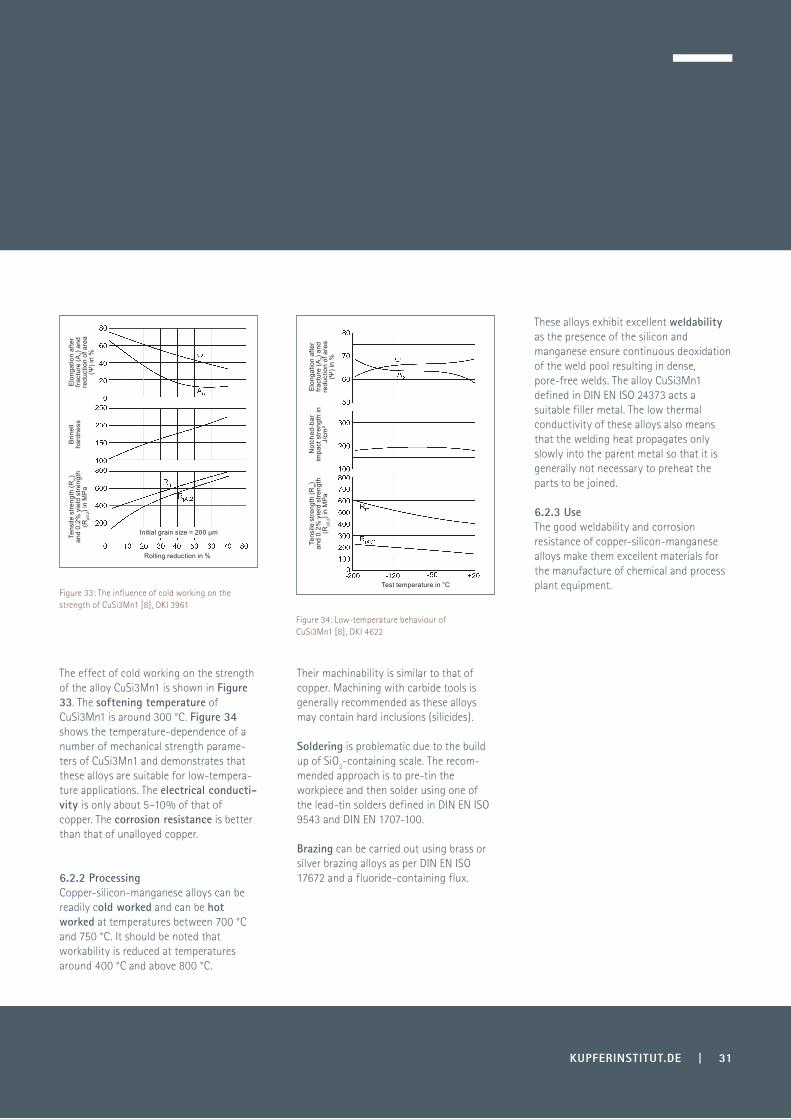
6.2.1 PropertiesSilicon significantly improves the mechani-cal properties of copper (Fig. 32). The addition of 3% of silicon improves the strength of copper to the same extent as adding around 42% Zn, 8% Al or 6% Sn. The addition of silicon also improves workability.
The presence of the alloying elements silicon and manganese produces greater hardening of the material as a result of cold working than is achievable in pure copper.
6.1 Copper-manganese alloysCopper and manganese form homoge-neous alloys up to a manganese content of about 20 %.
These alloys are oxygen-free due to the deoxidizing effect of the manganese and are therefore resistant to reducing gases even at high temperatures.
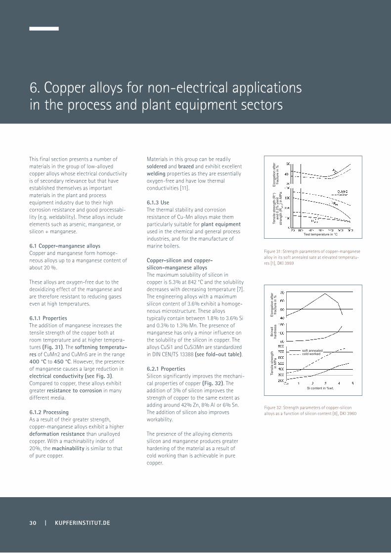
6.1.1 PropertiesThe addition of manganese increases the tensile strength of the copper both at room temperature and at higher tempera-tures (Fig. 31). The softening temperatu-res of CuMn2 and CuMn5 are in the range 400 °C to 450 °C. However, the presence of manganese causes a large reduction in electrical conductivity (see Fig. 3). Compared to copper, these alloys exhibit greater resistance to corrosion in many different media.
6.1.2 ProcessingAs a result of their greater strength, copper-manganese alloys exhibit a higher deformation resistance than unalloyed copper. With a machinability index of 20%, the machinability is similar to that of pure copper.
6. Copper alloys for non-electrical applications in the process and plant equipment sectors
Figure 31: Strength parameters of copper-manganese alloy in its soft annealed sate at elevated temperatu-res [1], DKI 3959
Figure 32: Strength parameters of copper-silicon alloys as a function of silicon content [8], DKI 3960
Elo
ngat
ion
afte
r fra
ctur
e in
%
Test temperature in °C
Tens
ile s
treng
th (R
m)
and
0.2%
yie
ld
stre
ngth
(Rp0
.2) i
n M
Pa
Si content in %wt.
soft annealedcold worked
Elo
ngat
ion
afte
r fra
ctur
e in
%B
rinel
l ha
rdne
ssTe
nsile
stre
ngth
in
MP
a
The effect of cold working on the strength of the alloy CuSi3Mn1 is shown in Figure 33. The softening temperature of CuSi3Mn1 is around 300 °C. Figure 34 shows the temperature-dependence of a number of mechanical strength parame-ters of CuSi3Mn1 and demonstrates that these alloys are suitable for low-tempera-ture applications. The electrical conducti-vity is only about 5–10% of that of copper. The corrosion resistance is better than that of unalloyed copper.
Their machinability is similar to that of copper. Machining with carbide tools is generally recommended as these alloys may contain hard inclusions (silicides).
These alloys exhibit excellent weldability as the presence of the silicon and manganese ensure continuous deoxidation of the weld pool resulting in dense, pore-free welds. The alloy CuSi3Mn1 defined in DIN EN ISO 24373 acts a suitable filler metal. The low thermal conductivity of these alloys also means that the welding heat propagates only slowly into the parent metal so that it is generally not necessary to preheat the parts to be joined.
6.2.3 UseThe good weldability and corrosion resistance of copper-silicon-manganese alloys make them excellent materials for the manufacture of chemical and process plant equipment.
Soldering is problematic due to the build up of SiO2-containing scale. The recom-mended approach is to pre-tin the workpiece and then solder using one of the lead-tin solders defined in DIN EN ISO 9543 and DIN EN 1707-100.
Brazing can be carried out using brass or silver brazing alloys as per DIN EN ISO 17672 and a fluoride-containing flux.6.2.2 Processing
Copper-silicon-manganese alloys can be readily cold worked and can be hot worked at temperatures between 700 °C and 750 °C. It should be noted that workability is reduced at temperatures around 400 °C and above 800 °C.
KUPFERINSTITUT.DE | 31
Figure 33: The influence of cold working on the strength of CuSi3Mn1 [8], DKI 3961
Figure 34: Low-temperature behaviour of CuSi3Mn1 [8], DKI 4622
Elo
ngat
ion
afte
r fra
ctur
e (A
5) an
d re
duct
ion
of a
rea
(Ψ) i
n %
Elo
ngat
ion
afte
r fra
ctur
e (A
5) an
d re
duct
ion
of a
rea
(Ψ) i
n %
Brin
ell
hard
ness
Not
ched
-bar
im
pact
stre
ngth
in
J/cm
²
Tens
ile s
treng
th (R
m)
and
0.2%
yie
ld s
treng
th
(Rp0
.2) i
n M
Pa
Test temperature in °C
Rolling reduction in %
Initial grain size = 200 µmTens
ile s
treng
th (R
m)
and
0.2%
yie
ld s
treng
th
(Rp0
.2) i
n M
Pa
32 | KUPFERINSTITUT.DE
Dispersion-strengthened coppers contain 0.15–0.6%vol. of finely dispersed particles, such as Al2O3, ranging in size from 3 nm to 12 nm. They are produced using powder metallurgical methods and combine the high electrical conductivity of copper with the high strength of the composite ma-terial. Because of the way in which these dispersoid materials are produced, they are best classified as composites and are men-tioned here for the sake of completeness.
7. Dispersion-strengthened materials

KUPFERINSTITUT.DE | 33
Publishing information
Issued by:
Picture credits:Aurubis AGBuntmetall Amstetten GmbH Gebr. Kemper GmbH & Co. KG LEONI Draht GmbHKME Germany GmbH & Co. KG Piel & Adey GmbH & Co. KG Swissmetall AG
Revised by:Dr. Alexander Lerch Helge LehmannDr. Uwe Hofmann Dr. Michael Köhler Ahmad ParsiDr. Dirk Rode Vincent RunserDr. Jürgen Schmidt Volker TietzDr. Ladji Tikana Dietmar Zenker
34 | KUPFERINSTITUT.DE
8. Literature / Technical Standards
[1] Niedriglegierte Kupferlegierungen, Fachbuch; Deutsches Kupferinstitut, Berlin (1966)
[2] F. Pawlek, K. Reichel: Der Einfluss von Verunreinigungen auf die elektrische Leitfähigkeit von Kupfer. Z. f. Metallkde. 47 (1956), p. 347–351
[3] E. Tuschy: Kupferwerkstoffe für die Elektrotechnik. Metall 17 (1963),p. 1122–1133
[4] A. Baukloh, K. Drefahl, U Heubner, M. Rühle: Zeitstanduntersuchungen an niedrig- und unlegierten Kupferwerkstof-fen Metall 30 (1976), p. 19–26
[5] Metals Handbook; Hrsg The American Society for Metals. Cleveland (1961)
[6] Werkstoff-Handbuch Nichteisenme-talle; Teil 111 Cu. VDI-Verlag. Düsseldorf (1960)
[7] K. Dies: Kupfer und Kupferlegierungen in der Technik. Springer Verlag. Berlin 1967
[8] H. J. Wallbaum in Landolt-Bornstein: Zahlenwerte und Funktionen IV Bd., 2. Teil, Bandteil b, p. 639-690 Springer-Verlag, Berlin (1964) (new edition – DKI)
[9] H. Hübner: Kupfer in Motoren und Generatoren. Metall 26 (1972), p. 1172–1173
[10] H.-G. Petri; H. Voßkühler: Kup-fer-Chrom-Knetlegierungen als Werkstoffe für die Elektrotechnik ETZ-A 76 (1955), p. 360–385
[11] H. Haseke, R Köcher: CuMn2 – Herstel-lung Eigenschaften, schweißtechnische Verarbeitung und Anwendung, Metall 26 (1972), p. 333–241
[12] M. G. Corson: “Copper Hardened by a New Method”, Z. Metallkde 19 (1927), p. 370–371
[13] S. A. Lockyer, F.M. Noble: “Precipitate Structure in a Cu-Ni-Si Alloy”, J. Mater. Sci. 29 (1994), p. 218
[14] A. Bögel: “Spannungsrelaxation in Kupfer-Legierungen für Steckverbinder und Federelemente” METALL 48 (1994), p. 872
[15] J. Kinder, J. Fischer-Bühner: “Ausschei-dungsuntersuchungen an höherfesten und höher leitfähigen CuNi2Si-Legierungen”, METALL 59 (2005), p. 722
[16] H.-A. Kuhn, A. Käufler, D. Ringhand,S. Theobald: “A New High Performance Copper Based Alloy for Electromechanical Connectors”, Mat.-Wiss. U. Werkstofftech. 38 (2007), p. 624
[17] M. Bohsmann, S. Gross: “Understan-ding Stress Relaxation”, Matscience Techn. 2008, Pittsburgh /USA, Oct 5-9, 2008, Conf. Proceeding, p. 41
[18] J. Kinder, D. Hüter: “TEM-Untersu-chungen an höherfesten und elektrisch hoch leitfähigen CuNi2Si-Legierungen” METALL 63 (2009), p. 298
[19] D. Ringhand: “Einflussgrößen bei der umformtechnischen Verarbeitung von Hochleistungs-Kupferwerkstoffen”, METALL 63 (2009), p. 304
[20] J. R. Davis: Copper and Copper alloys, ASM International, (2001)
[21] J. Günter, J. A. K. Kundig: Copper – Its trade, manufacture, use and environmen-tal status, ASM International & ICA, (1999)
[22] D.K. Crampton, H.L. Burghoff: The copper-rich alloys of the copper-ni-ckel-phosphorus system, Trans AIME 137, (1940)
[23] M. Jasner, http://www.copper.org/ applications/cuni/txt_KME.html
[24] Deutsches Kupferinstitut: Legierungen des Kupfers mit Zinn, Nickel, Blei und anderen Metallen, Berlin (1970)

Standards*
Basic standardsDIN CEN/TS 13388 Compendium of compositions and productsDIN EN 1172 Sheet and strip for building purposesDIN EN 12163 Rod for general purposesDIN EN 12164 Rod for free machining purposesDIN EN 12165 Wrought and unwrought forging stockDIN EN 12166 Wire for general purposesDIN EN 12167 Profiles and bars for gene-ral purposesDIN EN 12168 Hollow rod for free machi-ning purposesDIN EN 12288 Industrial valves – Copper alloy gate valvesDIN EN 12420 ForgingsDIN EN 12449 Seamless round tubes for general purposesDIN EN 12450 Seamless round copper capillary tubesDIN EN 12451 Seamless round tubes for heat exchangersDIN EN 12452 Rolled, finned, seamless tubes for heat exchangersDIN EN 13148 Hot-dip tinned stripDIN EN 13599 Copper plate, sheet and strip for electrical purposesDIN EN 13601 Copper rod, bar and wire for general electrical purposesDIN EN 1412 European numbering systemDIN EN 14436 Electrolytically tinned strip;DIN EN 1652 Plate, sheet, strip and circles for general purposesDIN EN 1653 Plate, sheet and circles for boilers, pressure vessels and hot water storage unitsDIN EN 1654 Strip for springs and con-nectorsDIN EN 1758 Strip for lead framesDIN EN 1982 Ingots and castings
KUPFERINSTITUT.DE | 35
Standards relating to joining techniquesDIN EN 29453 (ISO 9453) Soft solder alloysDIN EN 1707-100 Soft solder alloysDIN EN 29454-1 (ISO 9454-1) Soft soldering fluxesDIN EN 1045 Fluxes for brazingDIN EN ISO 17672 Brazing – Filler metalsDIN EN ISO 24373 Welding consumables
*) This list does not claim to be complete. The most recent edition of each standard shall apply.

Deutsches Kupferinstitut Berufsverband e. V. Heinrich Straße 2440239 Düsseldorf
Phone: +49 211 239469-0Fax: +49 211 239469-10
[email protected] www.kupferinstitut.de
Copy
right
© 2
012.
Pub
licat
ion
code
ann
otat
ion.


![Production of High Efficiency Complex Alloyed Steels and Alloys with Ceramic … · 2013. 12. 2. · powders is air-jet mill, and for refractory compounds - vibration mill [1]. Hot](https://img.dokumen.tips/doc/110x75/60c44aea2d2e874286204461/production-of-high-efficiency-complex-alloyed-steels-and-alloys-with-ceramic-2013.jpg)