Embed Size (px)
Citation preview

LOTAR EAS 2016-2017Phase 1 Pilot Studies Description
April 2017
© LOTAR 2017 All rights reserved
Contents
Background LOTAR International Engineering Analysis and Simulation (EAS) Workgroup
Testing and Development of LOTAR Standards and Supporting SoftwareOverview of Pilot Studies #1, #2 and #3ATS1m4 Model DetailsATS2m4 Model DetailsATS3m4 Model DetailsATS4m4 Model DetailsSummary
© LOTAR 2017 All rights reserved - April 2017 - Page 2
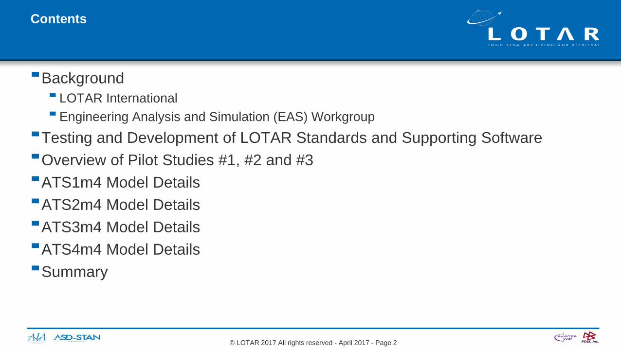
LOTAR “On A Page”Details at www.lotar-international.org
LOTAR is an international consortium of Aerospace manufacturers
Prime objective is creation and deployment of the EN/NAS 9300 series standard for long-term archiving and retrieval of digital data, based on standardized approaches and solutions.
Integration of LOTAR requirementsin software tools ensured by close cooperation with theCAx Implementor Forum (CAx-IF): Facilitated by PDES, Inc. and ProSTEP iViP Consists of CAD, STEP Translator, and Validation Tool
vendors Supports AP203, AP209, AP214, AP242
Similar PDM-IF currently in operation
Industry Associations
Membership Associations
Americas Europe
Requirements Harmonized ApproachesInteroperable STEP Products
EN = European Norm (Standard)NAS = National Aerospace StandardCAx = Computer Aided “x” (Design, Engineering…)PDM = Product Data Management
© LOTAR 2017 All rights reserved - April 2017 - Page 3

Creation of a LOTAR WG for engineering analysis and simulation data
The LOTAR Engineering Analysis & Simulation Working Group was created in Dec. 2014 Team Members and LOTAR Member companies involved in the activities of the Engineering Analysis
and Simulation Working Group
© LOTAR 2017 All rights reserved - April 2017 - Page 4
Jochen BoyPROSTEP AG Darmstadt, DE-HE
Rodrigo BrittoEmbraer S/ASão José dos Campos, BR-SP
Phil RoscheACCR, LCCSummerville, US-SC
Albert LévyEU Co-leaderCIMPA S.A.S. (on behalf of Airbus)Blagnac, FR-N
Chris JohnsonLockheed Martin Fort Worth, US-TX
Joe DraperAmericas Co-leaderBoeing Everett, US-WA
Randy CigelBoeing Seattle, US-WA
Gerrit RollemaAirbus Filton, GB-GLS
Torben LindemannAirbusManching, DE-BY
Jean-Marc CrepelAFNeT Paris, FR-J
Legend
Leaders
Members
Facilitators
Rod DreisbachBoeing - retired
Keith HuntenLockheed Martin - retired
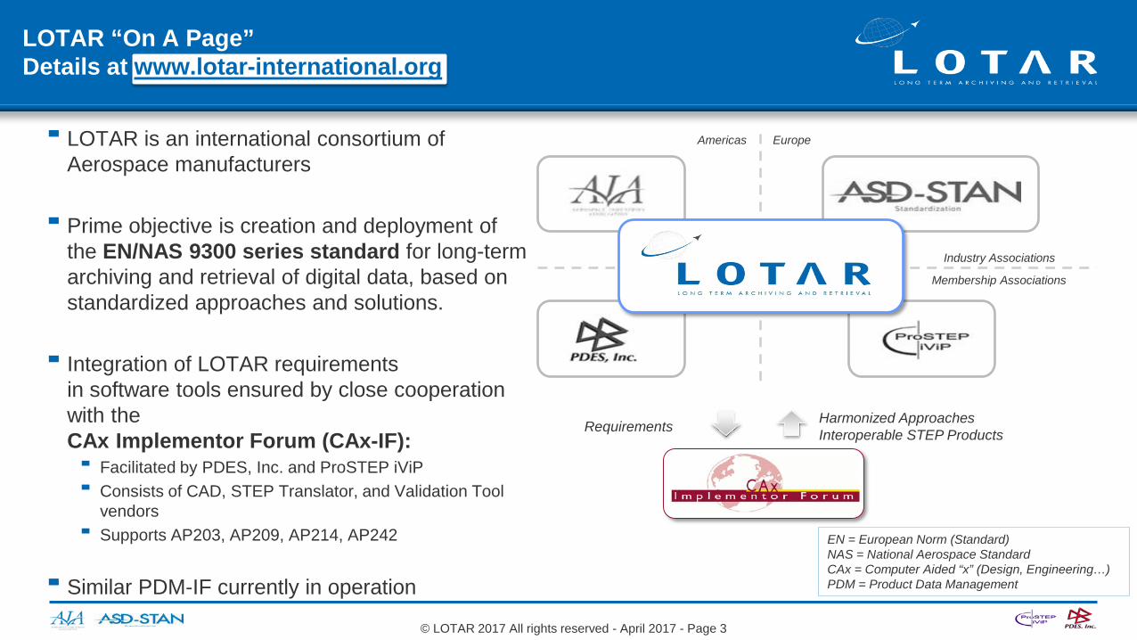
Primary technology for data exchange – ISO STEP AP209 ed2
ISO STEP AP209 ed2
5, 10, 15, 20, 30,…, or more years
Model Results Context Pedigree
Primary Technical ApproachOriginal Recovered for review or reuse
The primary technical approach is based on using a vendor-neutral ISO STEP AP209 ed2 data model. The complete archive of analysis and simulation data will be based on fulfilling the requirements of the member companies. ISO STEP AP209 ed2 is an enabling technology for preserving engineering analysis input and results for the long-term.The scope of Phase 1 of the LOTAR EAS WG is currently limited to linear quasi-static structures FEA.
“Multi-disciplinary analysis and design”
© LOTAR 2017 All rights reserved - April 2017 - Page 5

Introduction to Testing/Development
Testing follows a building block approach synchronized with the development of the standard and the supporting software
EAS Workgroup is developing a suite of finite element models test problems to support the development and testing of AP 209 ed2 enabled software The pilot study test problems are not inclusive of all FEA requirements (additional models will be
added in future test rounds)
Benchmark Tests
Use Case Tests
Pilot Study Tests
+com
plex
ity
Number of tests
Mat
urity
SimpleTests(Pilot Study)
Use Case Tests(CAE-IF)
Benchmark Tests(Benchmark)
Time4Q2016 3Q2017 ???
© LOTAR 2017 All rights reserved - April 2017 - Page 6
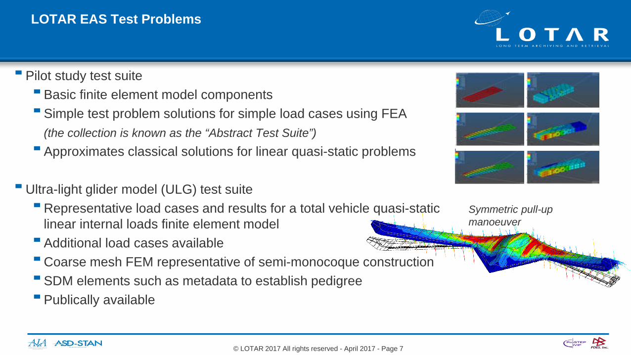
LOTAR EAS Test Problems
Pilot study test suite Basic finite element model components Simple test problem solutions for simple load cases using FEA
(the collection is known as the “Abstract Test Suite”) Approximates classical solutions for linear quasi-static problems
Ultra-light glider model (ULG) test suiteRepresentative load cases and results for a total vehicle quasi-static
linear internal loads finite element model Additional load cases availableCoarse mesh FEM representative of semi-monocoque construction SDM elements such as metadata to establish pedigree Publically available
Symmetric pull-up manoeuver
© LOTAR 2017 All rights reserved - April 2017 - Page 7
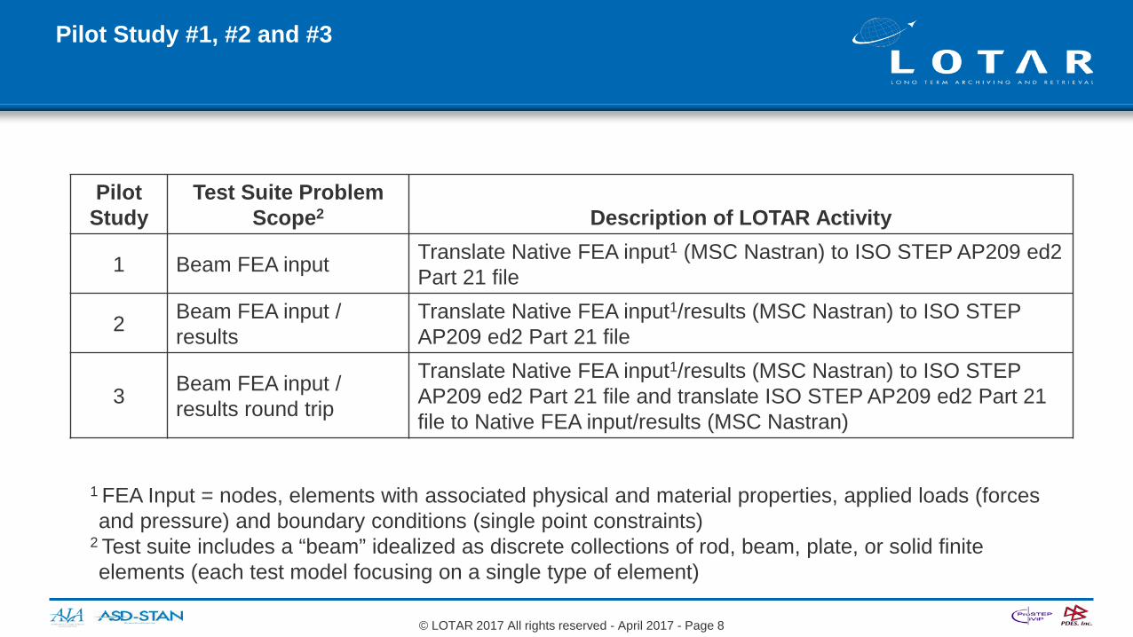
Pilot Study #1, #2 and #3
PilotStudy
Test Suite Problem Scope2 Description of LOTAR Activity
1 Beam FEA input Translate Native FEA input1 (MSC Nastran) to ISO STEP AP209 ed2 Part 21 file
2 Beam FEA input / results
Translate Native FEA input1/results (MSC Nastran) to ISO STEP AP209 ed2 Part 21 file
3 Beam FEA input / results round trip
Translate Native FEA input1/results (MSC Nastran) to ISO STEP AP209 ed2 Part 21 file and translate ISO STEP AP209 ed2 Part 21 file to Native FEA input/results (MSC Nastran)
© LOTAR 2017 All rights reserved - April 2017 - Page 8
1 FEA Input = nodes, elements with associated physical and material properties, applied loads (forces and pressure) and boundary conditions (single point constraints)
2 Test suite includes a “beam” idealized as discrete collections of rod, beam, plate, or solid finite elements (each test model focusing on a single type of element)

Pilot Study #1 – Using Beam Tests –Translate native FEA input data to ISO STEP AP 209 ed2 Files
(loop test for B=B)
(loop test for A=A)
Test4Test3Test2Test1Test Models in native FEA format for input1
Vendor A Process:consume native input and generate ISO STEP AP209 ed2 file
Vendor B Process:Consume native input and generate ISO STEP AP209 ed2 file
Processes (including standalone translators) to consume native FEA input and generate ISO STEP AP209 ed2 file
2
Test1_AP209e2_A.stp Test1_AP209e2_B.stpISO STEP AP 209 ed2 files3
Cross-feed the ISO STEP AP 209 ed2 files (and perform loop tests)
4
Vendor A Process:Consume FEA input ISO STEP AP209 ed2 file
Vendor B Process:Consume FEA input ISO STEP AP209 ed2 file
Processes to consume ISO STEP AP 209 ed2 file5
(cross-feed test for AB=BA)
© LOTAR 2017 All rights reserved - April 2017 - Page 9

Pilot Study #2 – Using Beam Tests –Generate ISO STEP AP 209 ed2 Files from native FEA input/results data
(loop test for B=B)
(loop test for A=A)
Test4Test3Test2Test1Test Models in native FEA format for input/results1
Vendor A Process:consume native input/results and generate ISO STEP AP209 ed2 file
Vendor B Process:Consume native input/results and generate ISO STEP AP209 ed2 file
Processes (including standalone translators) to consume native FEA input/results and generate ISO STEP AP209 ed2 file
2
Test1_AP209e2_A.stp Test1_AP209e2_B.stpISO STEP AP 209 ed2 files3
Cross-feed the ISO STEP AP 209 ed2 files (and perform loop tests)
4
Vendor A Process:Consume FEA input/results ISO STEP AP209 ed2 file
Vendor B Process:Consume FEA input/results ISO STEP AP209 ed2 file
Processes to consume ISO STEP AP 209 ed2 file of FEM input/results
5
(cross-feed test for AB=BA)
© LOTAR 2017 All rights reserved April 2017 Page 10

Pilot Study #3 – Using Beam Tests – Bi-directionally generate ISO STEP AP 209 ed2 Files from native FEA input and results data
(loop test for B=B)
(loop test for A=A)
Test4Test3Test2Test1Test Models in native FEM format for node and element input1
Vendor A Process:consume native input/results and generate ISO STEP AP209 ed2 file
Vendor B Process:Consume native input/results and generate ISO STEP AP209 ed2 file
Processes (including standalone translators) to consume native FEA input/results and generate ISO STEP AP209 ed2 file
2
Test1_AP209e2_A.stp Test1_AP209e2_B.stpISO STEP AP 209 ed2 Part 21 files3
Cross-feed the ISO STEP AP 209 ed2 files (and perform loop tests)
4
Vendor A Process:Consume ISO STEP AP209 ed2 file and generate native input/results
Vendor B Process:Consume ISO STEP AP209 ed2 file and generate native input/results
Processes to consume ISO STEP AP 209 ed2 file and generate native FEM input/results
5
Test4Test3Test2Test1Test Models in native FEM format for input/results should result in “equivalent outcome” relative to the original input/results
Test4Test3Test2Test1
(cross-feed test for AB=BA)
6
Con
form
ance
test
ing
Inte
rop.
test
ing
© LOTAR 2017 All rights reserved - April 2017 - Page 11

Overview of Pilot Study Test Problems
EAS WG provides simple standardized models to test vendor implementations of ISO 10303 AP 209 ed2 (STEP) interfaces Initial focus is on linear quasi-static analysis FEA data structures and generating the required STEP
data model content (along with testing methodology development) Model definition uses NASTRAN card descriptions but could be represented by any vendor data model
capable of generating a compliant AP 209 ed2 STEP file (Documentation of NASTRAN input syntax is readily available on-line using any search engine: Search string = “NASTRAN quick reference guide”) Pilot study considers first 4 ATS models that will require implementation of basic AP 209 ed2 data
model elements Models represent 1D, 2D and 3D finite element abstractions of a constant section beam with various
boundary conditions and loads for which the theory and practice of engineering mechanics are well understood ATS models are identified with ‘ATS’ + model number + ‘m’ + version:
Length : 16.0 inchWidth : 4.0 inchHeight : 2.0 inchArea : 8.0 square inch
Beam (rectangular prism) models:ATS1m4 : idealized using “rod” elements ATS2m4 : idealized using “bar” elements ATS3m4 : idealized using “shell” elementsATS4m4 : idealized using “solid” elements
© LOTAR 2017 All rights reserved - April 2017 - Page 12

ATS1m4 Model Details
Beam (rectangular prism) idealized using “rod” elements (axial stiffness element, no torsional stiffness) FE model composition
Elements: 16 CROD Nodes: 17 GRID Loads: 1 FORCE Boundary: 1 SPC1 Property: 1 PROD Material: 1 MAT1 (aluminum) System: 1 CORD2R (at origin)
Subcase and output requests Subcases: 1 SUBCASE Boundary: 1 SPC Loads: 1 LOAD Output: 4 GPFORCE (global)
DISPLACEMENTSPCFORCESSTRESS
Isotropic aluminum material property at room temperature (see listing)
1000 lb axial load in compressive (-x) direction Rectangular coordinate system at origin with model at [0, -2, 1] *basic
Axial stress: 1000 / 8 = 125 psiAxial strain: 125 / 10e+6 = 1.25e-5 in/inAxial defl: 1.25e-5 x 16 = 0.0002 in
*See listing for output parameters
© LOTAR 2017 All rights reserved - April 2017 - Page 13
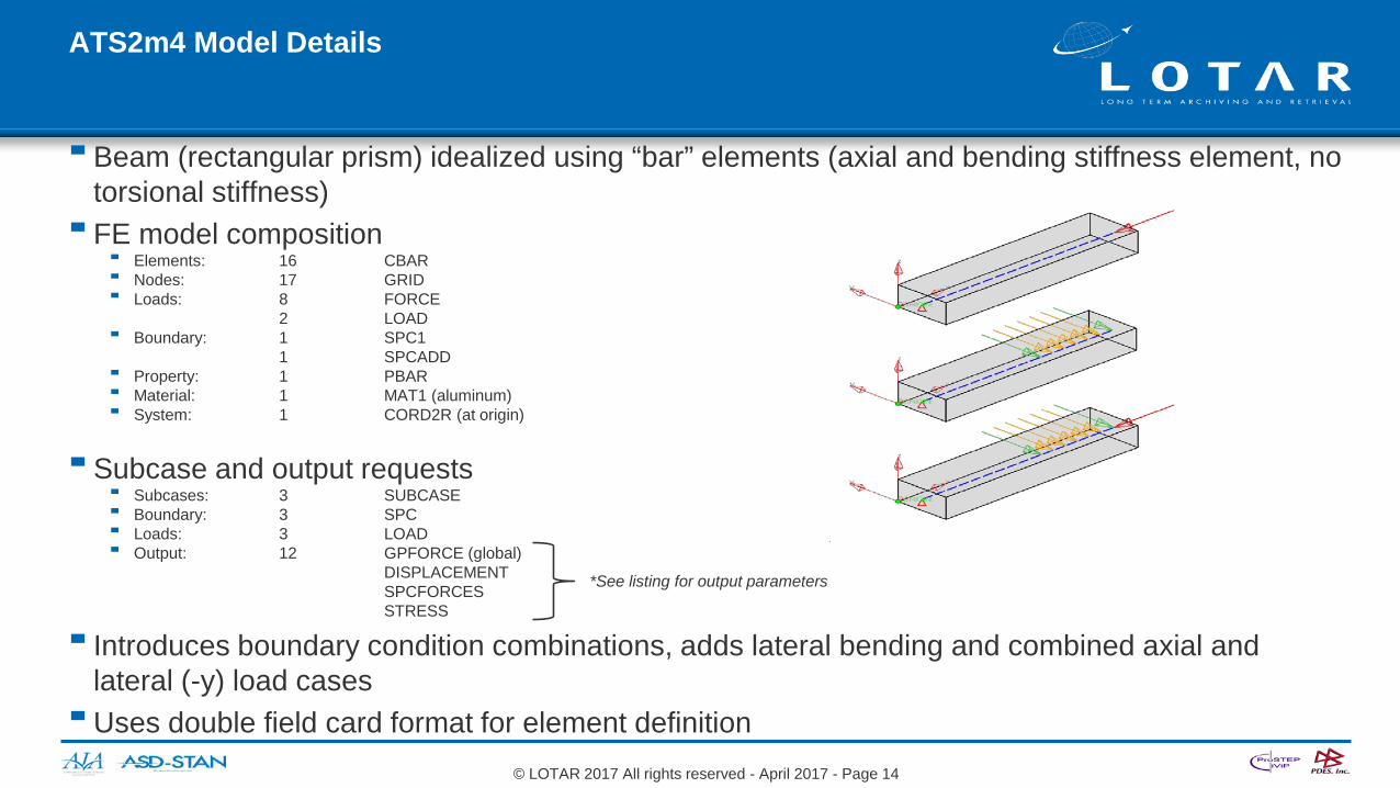
ATS2m4 Model Details
Beam (rectangular prism) idealized using “bar” elements (axial and bending stiffness element, no torsional stiffness) FE model composition
Elements: 16 CBAR Nodes: 17 GRID Loads: 8 FORCE
2 LOAD Boundary: 1 SPC1
1 SPCADD Property: 1 PBAR Material: 1 MAT1 (aluminum) System: 1 CORD2R (at origin)
Subcase and output requests Subcases: 3 SUBCASE Boundary: 3 SPC Loads: 3 LOAD Output: 12 GPFORCE (global)
DISPLACEMENTSPCFORCESSTRESS
Introduces boundary condition combinations, adds lateral bending and combined axial and lateral (-y) load cases Uses double field card format for element definition
*See listing for output parameters
© LOTAR 2017 All rights reserved - April 2017 - Page 14
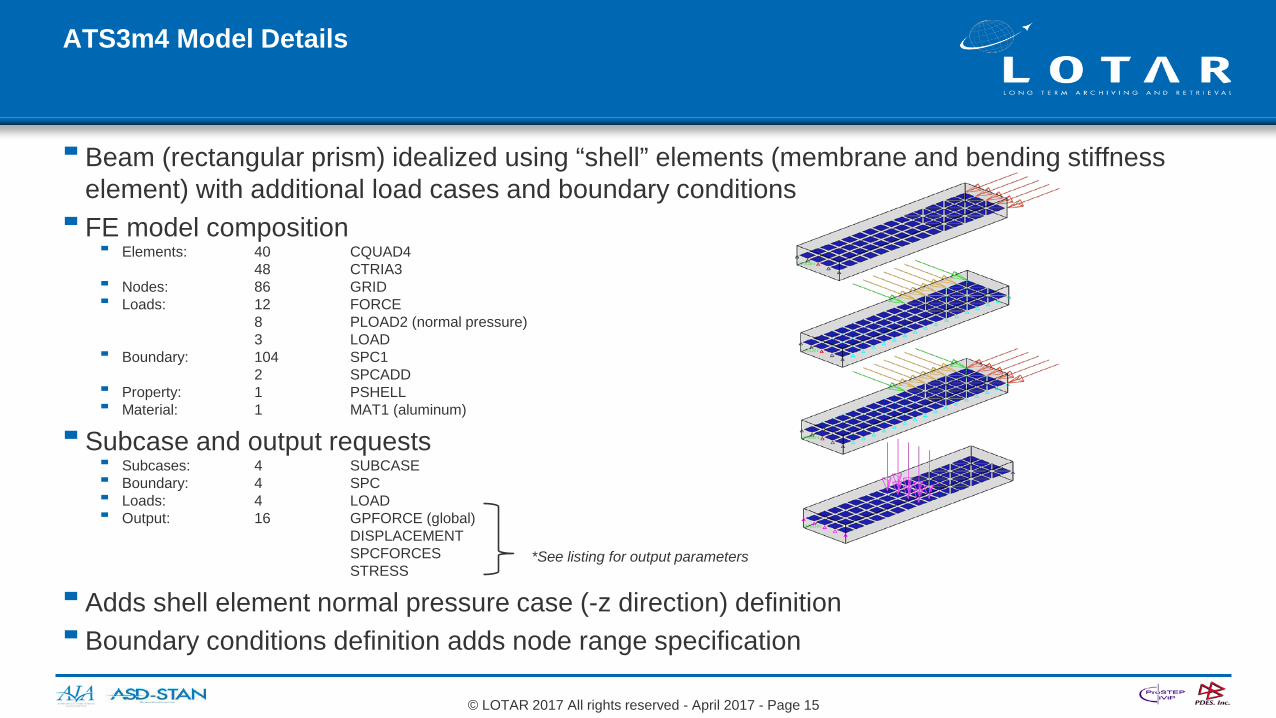
ATS3m4 Model Details
Beam (rectangular prism) idealized using “shell” elements (membrane and bending stiffness element) with additional load cases and boundary conditions FE model composition
Elements: 40 CQUAD448 CTRIA3
Nodes: 86 GRID Loads: 12 FORCE
8 PLOAD2 (normal pressure)3 LOAD
Boundary: 104 SPC12 SPCADD
Property: 1 PSHELL Material: 1 MAT1 (aluminum)
Subcase and output requests Subcases: 4 SUBCASE Boundary: 4 SPC Loads: 4 LOAD Output: 16 GPFORCE (global)
DISPLACEMENTSPCFORCESSTRESS
Adds shell element normal pressure case (-z direction) definition Boundary conditions definition adds node range specification
*See listing for output parameters
© LOTAR 2017 All rights reserved - April 2017 - Page 15
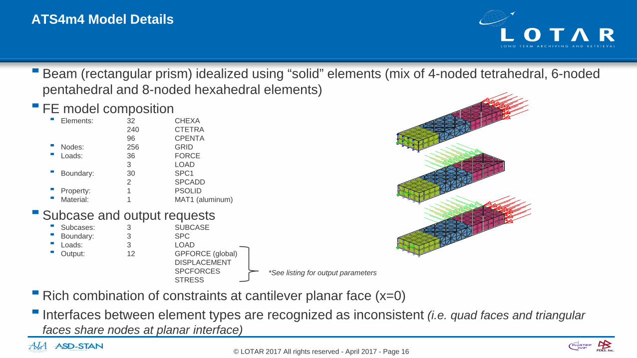
ATS4m4 Model Details
Beam (rectangular prism) idealized using “solid” elements (mix of 4-noded tetrahedral, 6-noded pentahedral and 8-noded hexahedral elements) FE model composition
Elements: 32 CHEXA240 CTETRA96 CPENTA
Nodes: 256 GRID Loads: 36 FORCE
3 LOAD Boundary: 30 SPC1
2 SPCADD Property: 1 PSOLID Material: 1 MAT1 (aluminum)
Subcase and output requests Subcases: 3 SUBCASE Boundary: 3 SPC Loads: 3 LOAD Output: 12 GPFORCE (global)
DISPLACEMENTSPCFORCESSTRESS
Rich combination of constraints at cantilever planar face (x=0) Interfaces between element types are recognized as inconsistent (i.e. quad faces and triangular
faces share nodes at planar interface)
*See listing for output parameters
© LOTAR 2017 All rights reserved - April 2017 - Page 16

Summary
The pilot test problems are not inclusive of all FEA requirements (additional models that include more element types, materials, composites, solutions and results will be added in future test rounds)Testing additional metadata such as analysis product structure and idealized
geometry association is also plannedVendor feedback on both test problem definitions and testing methodology is
welcomed
© LOTAR 2017 All rights reserved - April 2017 - Page 17