Embed Size (px)
Citation preview

pISSN 0301-2875, eISSN 2005-3789 17
서론
일반적으로 국소의치는 모형의 서베잉, 블록 아웃, 내화모형 제작, 왁스업, 주조과정 등을 거쳐 제작되며 이러한 모든 과정이 수작업으로 진행된다. 만약, 지대치의 서베이드 크라운이 필요한 경우에는 국소의치 제작 전에 고정성 보철물의 제작 과정이 선행되어야 하므로 이를 위한 기공 과정뿐만 아니라 환자의 내원 횟수도 많아지게 된다. 이러한 전반적인 과정들은 많은 재료와 시간이 소요되며 치과의사나 기공사에 따라 기술적 차이가 있을 수 있다. CAD/CAM (Computer Aided Design/Computer Aided Manufacturing)을 활용한 고정성 보철물 제작이 보편화
되면서 치과 보철학 분야 전반에 디지털 치의학 개념이 이용되고 있다. 2005년 Eggbeer1는 CAD와 쾌속조형술(rapid prototyping)을 이용한 디지털 국소의치를 소개하였다. 이는 통상적인 방법으로 인상 채득하여 얻은 모형을 스캔하고, CAD 프로그램을 통해 서베잉하고 가철성 국소의치 금속구조물을 디자인하고, 쾌속조형술을 이용하여 레진 패턴을 제작하고 이를 매몰, 소환, 주조 과정을 거쳐 금속구조물을 제작한다. 본 증례에서는 부분 무치악 환자에서 lost wax technique과 CAD를 이용해 pattern을 프린팅하여 이를 주조하는 방식으로 가철성 금속구조물을 각각 제작하여, 금속구조물과 서베이드 크라운의 적합도를 비교하였다.2
https://doi.org/10.4047/jkap.2018.56.1.17Clinical Article
Lost wax technique과 CAD를 이용한 pattern의 프린팅 방식으로 제작된
가철성 국소의치 금속구조물의 적합도 비교
최원준 � 우이형 � 김형섭* � 백장현
경희대학교 치과대학 치과보철학교실
Comparison of internal adaptation of removable partial denture metal frameworks made by
lost wax technique and printing technique of pattern using CAD
Wonjun Choi, Yi-Hyung Woo, Hyeong-Seob Kim*, Janghyun PaekDepartment of Prosthodontics, School of Dentistry, Kyung Hee University, Seoul, Republic of Korea
Lost wax technique of casting wax patterns has been used principally to make metal frameworks of removable partial dentures. Since the development of digital technology and CAD, metal frameworks can be built through digital surveying and framework designing. Many cases proved that resin patterns made by CAD printing method were well adapted to internal oral structure and final metal frameworks also showed good internal adaptation as well. The metal frameworks of a removable partial denture were made by both lost wax technique and CAD technique and were applied to a patient with severe alveolar bone loss. Using CAD data and fit checker, internal adaptation of both metal frameworks were evaluated by comparing the gap between surveyed crown and its structure. This study is to prove that metal frameworks by both techniques showed adaptation that can be applied in clinical field. (J Korean Acad Prosthodont 2018;56:17-24)
Keywords: Removable partial denture; Metal framework; Lost wax technique; Computer aided design
*Corresponding Author: Hyeong-Seob KimDepartment of Prosthodontics, School of Dentistry, Kyung Hee Uniiversity26, Kyungheedae-ro, Dongdaemun-gu, Seoul 02447, Republic of Korea+82 (0)2 958 9340: e-mail, [email protected] history: Received August 28, 2017 / Last Revision September 18, 2017 / Accepted September 27, 2017
2018 The Korean Academy of ProsthodonticsThis is an Open Access article distributed under the terms of the Creative Commons Attribution Non-Commercial License (http://creativecommons.org/licenses/by-nc/3.0) which permits unrestricted non-commercial use, distribution, and reproduction in any medium, provided the original work is properly cited.
c
cc

18 대한치과보철학회지 56권 1호, 2018년 1월
최원준�우이형�김형섭�백장현 Lost wax technique과 CAD를 이용한 pattern의 프린팅 방식으로 제작된 가철성 국소의치 금속구조물의 적합도 비교
증례
47세 남성 환자로 “앞니가 벌어지고 모든 치아가 다 흔들린다”는 주소로 내원하였다. 20년간 흡연을 하고 있고, 턱관절의 불편감이나 전신질환은 없었다. 상악 전치부의 치아 이동으로 인해 치간 이개가 관찰되며, 상하악 구치부의 치아상실로 인해 대합치가 과맹출 되어있다 (Fig. 1). 방사선 영상에서는 전반적인 치조골 흡수 양상을 보이고, 특히 상악 대구치 부위에서 심한 치조골 흡수 양상이 관찰된다 (Fig. 2).진단모형, 방사선 사진, 임상 검사 분석 등을 통해 치아의 상실과 정출된 치아로 인한 저작 기능의 저하, 불균일한 교합평면, 비심미적인 안모가 관찰되었다. 치주낭 깊이, 치아동요도 등의 검사3-5 결과를 바탕으로 치아를 평가하여 절망적인(hopeless) 예후와 불량(poor)한 예후를 보이는 치아들은 발치하기로 하였다. 치간 이동과 과맹출이 심한 상악 좌우측 견치와 하악 좌측 측절치 및 하악 우측 견치와 제1대구치는 의도적인 근관 치료를 하여 가철성 국소의치를 계획하였다. 발치하는 당일에 즉시의치(immediate denture)를 구내 장착하였다. 치료 전 처치 후, 진단 왁스업 및 인공치 배열하여 교합 평면 및 치아 배열 공간을 파악
했다. 진단 왁스업 제작 후 퍼티 인덱스(Perfect-F putty, Handae Chemical, Seongnam, Korea)를 제작하여, 그것을 참고로 지대치 삭제량을 확인하며 치아를 삭제했다. 부가중합형 실리콘 인상재(Imprint II Garant, 3M ESPE, St. Paul, MN, USA)로 인상 채득하여 주모형을 제작하였다. 환자의 교합을 중심위 상태로 유도해서 교합 인상재를 이용하여 악간 관계 기록을 채득한 후에, 교합기에 안궁이전하였다. 서베이드 크라운 제작을 위해 full
Fig. 2. Pre-operative panoramic view.
Fig. 1. Pre-operative intraoral view showing diastema and supra eruption. (A) Occlusal view of maxilla, (B) Lateral view (right side), (C) Frontal view, (D) Lateral view (left side), (E) Occlusal view of mandible.
A
C
E
B D

대한치과보철학회지 56권 1호, 2018년 1월 19
최원준�우이형�김형섭�백장현 Lost wax technique과 CAD를 이용한 pattern의 프린팅 방식으로 제작된 가철성 국소의치 금속구조물의 적합도 비교
contour 왁스업과 서베잉을 진행하고, 서베이드 크라운을 제작하였다. 금속구조물 제작을 위해 개인 트레이를 제작하고 변연을 형성하여 최종인상을 채득하였다. 금속구조물 제작은 첫 번째로 lost wax technique과 두 번째로 CAD (Computer aided design)를 이용해 제작한 pattern을 프린팅하여 이를 주조한 방식으로 각각 제작하여 서베이드 크라운과 금속 구조물간의 적합도를 비교하였다. Lost wax technique으로 금속구조물을 만드는 과정은 먼저 평행 블록 아웃을 하고 최소한으로 조직의 언더컷 부위를 릴리프하고 내화모형을 제작하여 금속구조물을 제작하였다.
CAD를 이용한 pattern의 프린팅 제작방법6은 먼저 주모형을 3Shape lab scanner D700 (3Shape A/S; Copenhagen, Denmark)
을 통해 스캔하고, Dental CAD software (exocad Dental CAD, exocad, Darmstadt, Germany)를 이용하여 스캔한 모델의 데이터를 오픈하여, 언더컷을 확인하고, 자동 블록 아웃 하였다. 이 후 차례대로 메쉬 영역과, 주연결장치 형태 조정, 클래스프와 피니쉬 라인을 디자인하여 완성하였다 (Fig. 3).디자인이 완료된 금속구조물을 3D 프린터(Projet DP 3000,
3D systems, Rock Hill, SC, USA)를 이용해 제작한 레진 패턴을 매몰, 소환, 주조하여 금속구조물을 제작하였다 (Fig. 4).7,8 각각의 금속구조물과 서베이드 크라운과의 적합도를 확인하기 위해 다섯개 서베이드 크라운에서 교합면 레스트와 설면 레스트 부위의 적합도를 살펴 보았다 (Fig. 5).
Fig. 3. Removable partial denture framework designed by CAD. (A) Scan data opening, (B) Undercut check, (C) Block out, (D) Mesh coverage setting, (E) Shape adjustment of major connector, (F) Clasp design, (G) Finish line setting, (H) Final framework design.
A CB D
E GF H
Fig. 4. Resin pattern of RPD framework. (A) Resin pattern of maxillary RPD framework was fabricated through rapid prototyping, (B) Metal framework fitted the model well, (C) Resin pattern of mandibular RPD framework was fabricated through rapid prototyping, (D) Metal framework fitted the model well.
A B
C D Fig. 5. Discrepancy measurement between rest and rest seat. (A) Section line of #13, #23 cingulum rest of maxilla, (B) Section line of #32, 43 cingulum rest and #46 occlusal rest of mandible.
A B

20 대한치과보철학회지 56권 1호, 2018년 1월
최원준�우이형�김형섭�백장현 Lost wax technique과 CAD를 이용한 pattern의 프린팅 방식으로 제작된 가철성 국소의치 금속구조물의 적합도 비교
금속구조물 각각의 레스트와 서베이드 크라운의 레스트 시트와의 유격을 모식화한 것으로, 레스트 각 부위마다 중심부와 상, 하 주변부로 총 세 단면으로 나눠서 적합도를 조사하였다 (Fig. 6).유격을 측정하는 방법으로는 CAD data와 fit checker (Fit
checkerII, GC, Japan)를 이용하였다. 먼저 CAD data는 주모형과 금속구조물을 스캔하여 이 둘을 중첩시킨 후 (Fig. 7A), 레스트와 레스트 시트 부위를 절단하여 Dental CAD software를 통하여 유격을 측정하였다 (Fig. 7B). 두번째 방법으로는 Lee 등7
이 내면의 적합도를 확인한 방법과 동일하게, 금속구조물의 레스트 부위에 fit checker를 도포한 후 환자 구강 내에 시적하여 알지네이트(Aromafine Plus, GC, Tokyo, Japan)로 픽업 인상채득 하였다 (Fig. 7C). 실리콘 인상재료 polyvinyl siloxane (Express, light body, 3M ESPE, St. Paul, MN, USA)을 이용해 서베이드 크라운 모양을 복제한 후 (Fig. 7D), 복제 모델을 나이프로 절단하여, 200배 확대경(Digibird USB digital microscope OPT-2000, Dalian, China)으로 fit checker의 두께를 확대하여 정밀측정(Adobe Photoshop CC program, San Jose, CA, USA)하였다 (Fig. 7E).
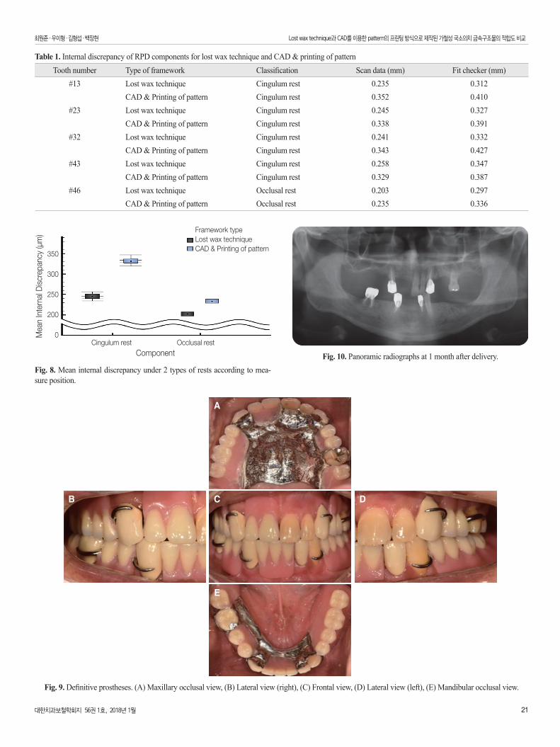
Table 1은 다섯개의 서베이드 크라운과 각각의 금속구조물간의 유격을 정리한 것으로 설면 레스트에서 lost wax technique은 평균 0.244 mm이고, CAD를 이용한 pattern의 프린팅 방식은 평균 0.330 mm의 유격을 보였다 (Fig. 8). 두 종류의 레스트에서 lost wax technique으로 제작한 경우가 유격이 더 작았으며, 설면 레스트 보다는 교합면 레스트에서 유격이 더 작은 것을 확인할 수 있었다.금속구조물 제작한 후에, 이어서 악간 관계기록 채득하고 마운팅 후 wax denture를 제작 후, 환자 구강 내에 시적 하였다. Injection type denture curing system (Palajet, Heraeus Kulzer, NY, USA)을 통해 의치를 온성 후에 의치를 장착하였다 (Fig. 9). 치료 완료 후 방사선 사진 (Fig. 10)으로 초진 시부터 관찰되었던 치조골 흡수 양상을 지속적으로 체크할 계획이다.
Fig. 6. (A) Occlusal rest; 1 measurement for center of rest (thick arrow), 2 for peripheries of rest (thin arrow), (B) Cingulum rest; 1 measurement for center (thick arrow), 2 for peripheries (thin arrow).
A B
Fig. 7. Measurement of gap between model and framework. (A) Overlapping the cast and the scan data of framework by using exocad Dental CAD, (B) Mea-suring the distance between framework and surveyed crown by slicing scan data of #46 occlusal rest, (C) Partial denture, including internal registration material, removed with alginate impression material, (D) Section line of replica, (E) Measuring the thickness of fit checker by magnifying cingulum rest.
A
C
D
B
D E
Distance:
대한치과보철학회지 56권 1호, 2018년 1월 21
최원준�우이형�김형섭�백장현 Lost wax technique과 CAD를 이용한 pattern의 프린팅 방식으로 제작된 가철성 국소의치 금속구조물의 적합도 비교
Table 1. Internal discrepancy of RPD components for lost wax technique and CAD & printing of patternTooth number Type of framework Classification Scan data (mm) Fit checker (mm)
#13 Lost wax technique Cingulum rest 0.235 0.312CAD & Printing of pattern Cingulum rest 0.352 0.410
#23 Lost wax technique Cingulum rest 0.245 0.327CAD & Printing of pattern Cingulum rest 0.338 0.391
#32 Lost wax technique Cingulum rest 0.241 0.332CAD & Printing of pattern Cingulum rest 0.343 0.427
#43 Lost wax technique Cingulum rest 0.258 0.347CAD & Printing of pattern Cingulum rest 0.329 0.387
#46 Lost wax technique Occlusal rest 0.203 0.297CAD & Printing of pattern Occlusal rest 0.235 0.336
Fig. 8. Mean internal discrepancy under 2 types of rests according to mea-sure position.
Framework typeLost wax techniqueCAD & Printing of pattern
Mea
n In
tern
al D
iscr
epan
cy (μ
m)
350
300
250
200
0Cingulum rest Occlusal rest Component Fig. 10. Panoramic radiographs at 1 month after delivery.
Fig. 9. Definitive prostheses. (A) Maxillary occlusal view, (B) Lateral view (right), (C) Frontal view, (D) Lateral view (left), (E) Mandibular occlusal view.
B C
A
E
D

22 대한치과보철학회지 56권 1호, 2018년 1월
최원준�우이형�김형섭�백장현 Lost wax technique과 CAD를 이용한 pattern의 프린팅 방식으로 제작된 가철성 국소의치 금속구조물의 적합도 비교
고찰
본 증례에서 서베이드 크라운과 각각의 금속구조물간의 유격은 설면 레스트에서 lost wax technique (평균 0.244 mm)이 CAD를 이용한 pattern의 프린팅 방식(평균 0.330 mm) 보다 작았다. 그리고 금속구조물을 제작한 두 방식 모두 교합면 레스트가 설면 레스트보다 유격이 더 작았다. Lee 등7은 lost wax technique에서 0.8 mm 릴리프를 주었고, CAD상에서 디자인 할 때는 0.6 mm 릴리프를 주었기에 그 둘의 유격 차이가 발생하였고, 설면 레스트에서 유격은 주변부(periphery)보다 중심부(center)에서 더 크다고 설명했다 (Fig. 6A, B). 이는 교합면 레스트에서 유격이 중심부와 주변부에서 큰 차이가 없기 때문에 설면 레스트보다 교합면 레스트에서 유격이 더 작았음을 알 수 있다. Dunham 등9은 레스트와 레스트 시트 간에 유격이 평균 2.41 mm이고, CAD를 이용한 pattern의 프린팅 방식으로 제작한 금속구조물 또한 임상적으로 이용 가능하다고 하였다. 본 원저에서 두 가지 방식으로 제작한 각각의 금속구조물이 서베이드 크라운과 유격을 확인하는 방법에 있어 세가지 오류의 문제가 있다. 첫 번째는, 한 명의 사람이 주모형과 CAD프로그램에서 동일한 위치와 양으로 릴리프를 부여한다고 하더라도 정확히 일치하지 않기 때문에 동일한 조건으로 비교하기 어렵다. 두 번째는, 스캔 데이터를 조사하는 과정에서, 두 방식으로 제작한 금속구조물의 외형이 서로 다르기 때문에, CAD프로그램에서 주모형과 금속구조물을 서로 완벽하게 중첩하는데 한계가 있다. 다시 말해, CAD프로그램에서 주모형과 금속구조물이 서로 닿는 부위에 점(point)을 지정하여 이를 연결하는 방식인데, 술자에 따라 정확도의 차이가 날 수 있다. 세 번째는, fit checker가 탄성이 있는 재료이기 때문에 복제 모형을 단면화 하는 과정에서 fit checker의 두께가 변형되어 오차가 발생할 수 있다. Lee 등7은 fit checker와 같은 실리콘 인상재료를 통해 만들어진 복제 모형은 절단하는 과정에서 변형과 수축이 발생할 수 있다고 설명했다. 하지만 두 가지 방식으로 제작된 각각의 금속구조물의 적합도는 임상적으로 이용 가능하고, 가철성 국소의치의 디지털 영역이 더 확대됨으로써 CAD를 이용한 pattern의 프린팅 방식은 활발히 연구될 것이다. Wu 등10은 기존의 왁스업으로 제작한 금속구조물과 비교했을 때 CAD를 통해서 좀 더 정밀한 디자인이 가능하고, 기공사의 기술적 차이 배제, 기공 시간의 단축, 편리한 재제작이 가능하다고 하였다. Kattadiyil 등11은 CAD를 이용한 pattern의 프린팅 방식으로 제작된 금속구조물은 구강 내에 정확하게 적합 되었고, 임상적으로 이용 가능하다고 보고하였다. Hong 등12은 CAD에서 전자 서베잉을 통해 유지암에 필요한 언더컷을 정밀하게 확인할 수 있고 삽입 철거로 또한 쉽게 확인할 수 있다고 하였다.최근에 가철성 국소의치 금속구조물 제작의 많은 발전을 통해, 합금을 분말로 가공하여 이를 레이저로 녹이면서 적층하는 SLM13(selective laser melting)기법이 소개되었다. 이를 통해 레진 패턴 제작 과정을 생략하고 금속구조물을 바로 밀링(milling)함으로써, 최종 결과물까지 디지털로 제작할 수 있고 오차발생
과 기공사의 기술적 차이를 줄일 수 있다. 최종 보철물 장착 1개월 후에 방사선 사진에서 이상소견 보이지 않았고, 서베이드 크라운의 파절이나 탈락은 없었으며 가철성 국소의치의 적합도 또한 양호했다. 환자는 기능적, 심미적으로 매우 만족하였으며 추후 정기적인 체크를 통해 의치의 적합도 정도를 검사할 계획이다.
결론
Lost wax technique과 CAD를 이용한 pattern의 프린팅 방식으로 가철성 국소의치의 금속구조물을 각각 제작하여 본 결과 두 방식 모두 임상적으로 받아들여질 만한 좋은 적합도를 보였다. 가철성 국소의치의 디지털 영역이 발전함으로써, 향후 CAD를 이용한 pattern의 프린팅 방식은 보다 정밀하고 정확한 금속구조물 제작이 가능하게 할 것이다.
ORCID
Hyeong-Seob Kim https://orcid.org/0000-0002-0964-0288
References
1. Eggbeer D, Bibb R, Williams R. The computer-aided design and rapid prototyping fabrication of removable partial denture frameworks. Proc Inst Mech Eng H 2005;219:195-202.
2. Park JM, Hong YS, Park EJ, Kim SK, Koak JY, Heo SJ. Study on the accuracy of digital removable partial denture and the comparison with the CAD model: A pilot study. Biomater Res 2012;16:102-7.
3. McGuire MK, Nunn ME. Prognosis versus actual outcome. II. The effectiveness of clinical parameters in developing an accurate prognosis. J Periodontol 1996;67:658-65.
4. McGuire MK, Nunn ME. Prognosis versus actual outcome. III. The effectiveness of clinical parameters in accurately pre-dicting tooth survival. J Periodontol 1996;67:666-74.
5. Faggion CM Jr, Petersilka G, Lange DE, Gerss J, Flemmig TF. Prognostic model for tooth survival in patients treated for periodontitis. J Clin Periodontol 2007;34:226-31.
6. Park SA, Koak JY, Heo SJ, Kim SK, Park JM. RPD frame-work fabrication using computer-aided design (CAD) and rapid prototyping. J Korean Acad Prosthodont 2017;55:94-9.
7. Lee JW, Park JM, Park EJ, Heo SJ, Koak JY, Kim SK. Ac-curacy of a digital removable partial denture fabricated by casting a rapid prototyped pattern: A clinical study. J Prosthet Dent 2017 Apr 4.
8. Fasbinder DJ. Clinical performance of chairside CAD/CAM restorations. J Am Dent Assoc 2006;137:22S-31S.
9. Dunham D, Brudvik JS, Morris WJ, Plummer KD, Cam-eron SM. A clinical investigation of the fit of removable partial dental prosthesis clasp assemblies. J Prosthet Dent 2006;95:323-6.
대한치과보철학회지 56권 1호, 2018년 1월 23
최원준�우이형�김형섭�백장현 Lost wax technique과 CAD를 이용한 pattern의 프린팅 방식으로 제작된 가철성 국소의치 금속구조물의 적합도 비교
10. Wu J, Wang X, Zhao X, Zhang C, Gao B. A study on the fab-rication method of removable partial denture framework by computer-aided design and rapid prototyping. Rapid Prototyp J 2012;18:318-23.
11. Kattadiyil MT, Mursic Z, AlRumaih H, Goodacre CJ. ntraoral scanning of hard and soft tissues for partial removable dental prosthesis fabrication. J Prosthet Dent 2014;112:444-8.
12. Hong YS, Park EJ, Kim SK, Koak JY, Heo SJ, Park JM. Sur-veyed restoration and RPD framework design utilizing elec-tronic surveying. J Korean Acad Prosthodont 2011;49:354-61.
13. Kanazawa M, Iwaki M, Minakuchi S, Nomura N. Fabrication of titanium alloy frameworks for complete dentures by selec-tive laser melting. J Prosthet Dent 2014;112:1441-7.

24 대한치과보철학회지 56권 1호, 2018년 1월
Clinical Article
Lost wax technique과 CAD를 이용한 pattern의 프린팅 방식으로 제작된
가철성 국소의치 금속구조물의 적합도 비교
최원준 � 우이형 � 김형섭* � 백장현
경희대학교 치과대학 치과보철학교실
가철성 국소의치의 금속구조물을 제작하는 방법은 왁스 패턴을 제작하여 주조하는 lost wax technique이 주로 사용되어 왔으나, 디지털 기술의 발달로 서베잉과 금속구조물을 CAD (Computer aided design)로 디자인하여 제작할 수 있게 되었다. 여러 증례에서 CAD를 이용한 pattern의 프린팅 방식으로 얻은 레진 패턴이 구강 내에 정확하게 적합 되었고 최종 금속구조물 또한 좋은 적합도를 보였다고 보고되었다. 본 원저는 치조골 소실이 심한 상, 하악 부분 무치악 환자에서 가철성 국소의치의 금속구조물을 두 가지 방식으로 각각 제작하였다. 첫 번째는 일반적인 lost wax technique과 두 번째는 CAD를 통해 pattern을 프린팅하여 금속구조물을 주조하는 방식으로 제작하여, CAD data와 fit checker를 이용해 금속구조물과 서베이드 크라운과의 유격을 측정함으로써 금속구조물의 적합도를 비교하였다. 두 가지 방식 모두 임상적으로 사용 가능한 금속구조물의 적합도를 얻었기에 이를 보고하고자 한다. (대한치과보철학회지 2018;56:17-24)
주요단어: 가철성 국소의치; 금속구조물; Lost wax technique; Computer aided design
*교신저자: 김형섭02447 서울 동대문구 경희대로 26 경희대학교 치과대학 치과보철학교실02 958 9340: e-mail, [email protected]원고접수일: 2017년 8월 28일 / 원고최종수정일: 2017년 9월 18일 / 원고채택일: 2017년 9월 27일
2018 대한치과보철학회이 글은 크리에이티브 커먼즈 코리아 저작자표시-비영리 3.0 대한민국 라이선스에 따라 이용하실 수 있습니다.
c
cc