Embed Size (px)
Citation preview
Loss of Coolant Accidents (LOCA) in PWRs:Deterministic View
Course 22.39
10/12/05
Professor Neil Todreas
10/12/05 Course 22.39, Lecture 9Professor Neil Todreas
1

10/12/05 Course 22.39, Lecture 9Professor Neil Todreas
2
Event Categories (from Lillington, UK)
DescriptionCategory Frequency/Reactor
2 ~1
3 ~10-2
1 ~10
4 ~10-4
5 ~10-6
Faults that are expected during the life of the plant: Anticipated moderately frequent events requiring safety response
Faults not expected during the life of a particular plant: Anticipated infrequent events requiring safety response
Conditions that occur regularly in normal operation
Improbable events not expected to occur in the nuclear industry but provided for by the design
Extremely improbable events not provided for in the design of the plant
Figure by MIT OCW. After Lillington, 1995.

10/12/05 Course 22.39, Lecture 9Professor Neil Todreas
3
Example Events(from Lillington, UK)
Events Categories
Loss of External GridLoss of FeedwaterLoss of Reactor Coolant Pump
Small LOCAValves Open
Bringing the Reactor to Full Power
Large LOCAMain Steam Line Break
2
3
1
4
LOCAs without ECCSTransients with Total Loss of ON- and Off-Site Power
5
Figure by MIT OCW. After Lillington, 1995.

Decay Power and Integral Decay Power As A Function of Time
By Charles Forsberg. Courtesy of Oak Ridge National Laboratory.
0.001
0.002
0.005
[MW
(th)]/
[MW
(th) R
eact
or O
utpu
t]
0.001
0.002
0.005
Inte
gral
Dec
ay P
ower
[MW
d]/[M
W(th
) Rea
ctor
Out
put]•
•
0.01
0.02
0.05
0.1
Dec
ay P
ower
0.01
0.02
0.05
0.1
Pressurized Water Reactor SNF Burnup: 33 GW(d)/MTIHM
0.01 0.02 0.05 0.1 0.2 0.5 1.0 2.0 5.0 10 20 50 100
Time (d)
Lecture 9 410/12/05 Course 22.39, Professor Neil Todreas 05-017
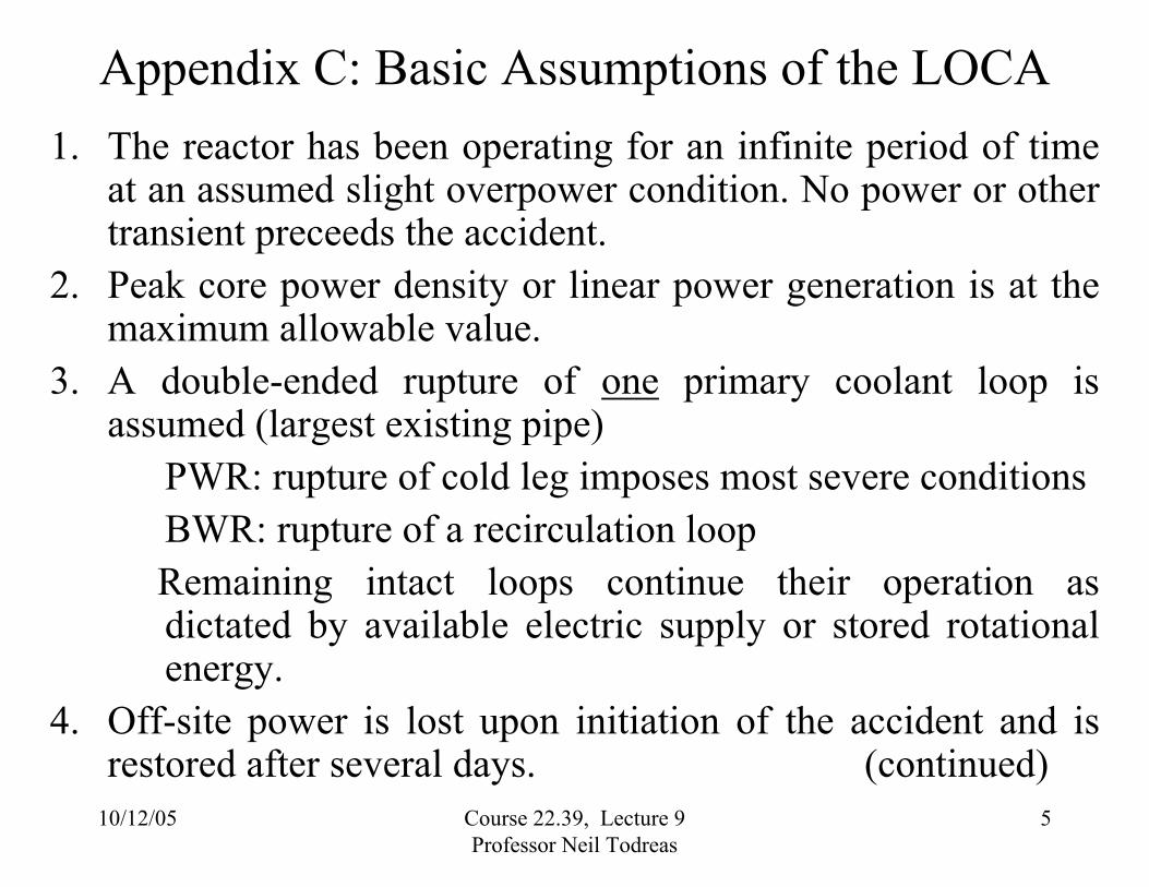
Appendix C: Basic Assumptions of the LOCA
1. The reactor has been operating for an infinite period of time at an assumed slight overpower condition. No power or other transient preceeds the accident.
2. Peak core power density or linear power generation is at the maximum allowable value.
3. A double-ended rupture of one primary coolant loop is assumed (largest existing pipe)
PWR: rupture of cold leg imposes most severe conditions BWR: rupture of a recirculation loop Remaining intact loops continue their operation as dictated by available electric supply or stored rotational energy.
4. Off-site power is lost upon initiation of the accident and is restored after several days. (continued)
10/12/05 Course 22.39, Lecture 9Professor Neil Todreas
5

5. Reactor scram systems need not contribute to the nuclear shut down because voiding of the core provides sufficient negative reactivity for shutdown.
6. The reactor is isolated after the initiation of the accident, i.e. the regular heat sink is removed.
PWR: Upon initiation of the accident the steam generators are isolated on the secondary side by closing the steam supply valves and the feedwater valves.
BWR: Upon receipt of a reactor-vessel low-water signal the main steam isolation valves close within 10 seconds. Feedwater flow ramps to zero within four seconds. (continued)
10/12/05 Course 22.39, Lecture 9Professor Neil Todreas
6

7. EECS are actuated automatically by appropriate signals. No corrective operator action is assumed for the first 10 minutes following initiation of the accident.
8. A single failure criterion is applied to the reactor system whereby an additional fault is postulated which may render inoperative any one of the following:
¾ Mechanical active components (e.g. pump)
¾ Active or passive electrical components
10/12/05 Course 22.39, Lecture 9 Professor Neil Todreas
7
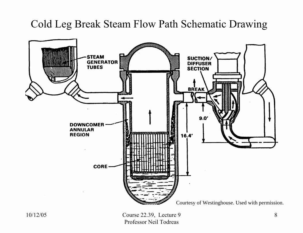
Cold Leg Break Steam Flow Path Schematic Drawing
10/12/05 Course 22.39, Lecture 9Professor Neil Todreas
8
Courtesy of Westinghouse. Used with permission.

Cold Leg Break Steam Flow Path
10/12/05 Course 22.39, Lecture 9Professor Neil Todreas
9
Courtesy of Westinghouse. Used with permission.
10/12/05 Course 22.39, Lecture 9Professor Neil Todreas
10
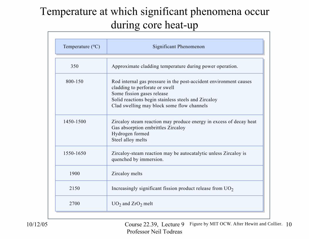
Temperature at which significant phenomena occurduring core heat-up
Significant PhenomenonTemperature (oC)
350
800-150
Approximate cladding temperature during power operation.
1900 Zircaloy melts
1550-1650 Zircaloy-steam reaction may be autocatalytic unless Zircaloy is quenched by immersion.
2150 Increasingly significant fission product release from UO2
2700 UO2 and ZrO2 melt
1450-1500 Zircaloy steam reaction may produce energy in excess of decay heatGas absorption embrittles ZircaloyHydrogen formedSteel alloy melts
Rod internal gas pressure in the post-accident environment causes cladding to perforate or swell Some fission gases releaseSolid reactions begin stainless steels and ZircaloyClad swelling may block some flow channels
Figure by MIT OCW. After Hewitt and Collier.

NRC Appendix K Criteria 1) Peak Cladding Temperature. The calculated maximum fuel element
cladding temperature shall not exceed 2200° F. 2) Maximum Cladding Oxidation. The calculated total oxidation of the
cladding shall nowhere exceed 0.17 times the total cladding thickness before oxidation.
3) Maximum Hydrogen Generation. The calculated total amount of hydrogen generated from the chemical reaction of the cladding with water or steam shall not exceed 0.01 times the hypothetical amount that would be generated if all the metal in the cladding cylinders surrounding the fuel, excluding the cladding surrounding the plenum volume, were to react.
4) Coolable Geometry. Calculated changes in core geometry shall be such that the core remains amenable to cooling.
5) Long-Term Cooling. After any calculated successful initial operation of the ECCS, the calculated core temperature shall be maintained at an acceptable low value and decay heat removed for the extended period of time required by the long-lived radioactivity remaining in the core.
10/12/05 Course 22.39, Lecture 9 Professor Neil Todreas
11

Diagrammatic representation of PWR primary and secondary circuits and the emergency cooling systems
Diagram removed for copyright reasons.Figure 4.4 in Collier, J. G., and G. F. Hewitt. Introduction to Nuclear Power.Washington, DC: Hemisphere Publishing, 1987.
10/12/05 Course 22.39, Lecture 9Professor Neil Todreas
12

Variation of peak clad temperature with time for a large-break LOCA
Graph removed for copyright reasons.Figure 4.19 in Collier, J. G., and G. F. Hewitt. Introduction to Nuclear Power.Washington, DC: Hemisphere Publishing, 1987.
10/12/05 Course 22.39, Lecture 9Professor Neil Todreas
13

LOCA Transient Periods
10/12/05 Course 22.39, Lecture 9Professor Neil Todreas
14
Courtesy of Westinghouse. Used with permission.

10/12/05 Course 22.39, Lecture 9Professor Neil Todreas
15
Events in the reactor pressure vessel during a large-break LOCA. a) Normal operation; b) blowdown phase; c) refill phase; d) reflood phase
Figure removed for copyright reasons.Figure 4.18 in Collier, J. G., and G. F. Hewitt. Introduction to Nuclear Power.Washington, DC: Hemisphere Publishing, 1987.

PWR Large Break LOCA Phases
10/12/05 Course 22.39, Lecture 9Professor Neil Todreas
16 Courtesy of Westinghouse. Used with permission.
PWR operating conditions
Figure removed for copyright reasons.Figure 4.5 in Collier, J. G., and G. F. Hewitt. Introduction to Nuclear Power.Washington, DC: Hemisphere Publishing, 1987.
10/12/05 Course 22.39, Lecture 9Professor Neil Todreas
17
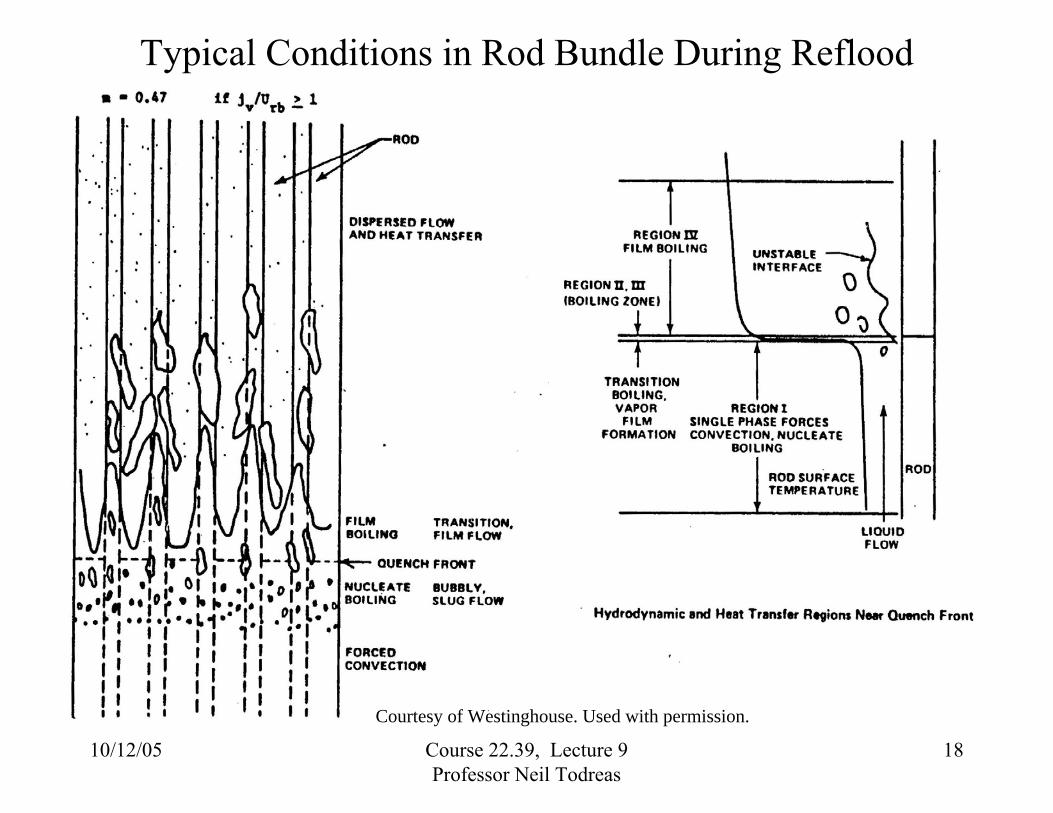
Typical Conditions in Rod Bundle During Reflood
10/12/05 Course 22.39, Lecture 9Professor Neil Todreas
18
Courtesy of Westinghouse. Used with permission.

Research Program to Address Appendix K Conservatisms
10/12/05 Course 22.39, Lecture 9 Professor Neil Todreas
19
Courtesy of Westinghouse. Used with permission.
Schematic calculated fuel clad temperatures for a PWR LOCA
A Guidebook to Nuclear Reactors. of California Press, 1979.
Graph removed for copyright reasons.
See: Figure 5-9 in Nero, A. V. Berkeley, CA: UniversityISBN: 0520034821.
10/12/05 Course 22.39, Lecture 9Professor Neil Todreas
20
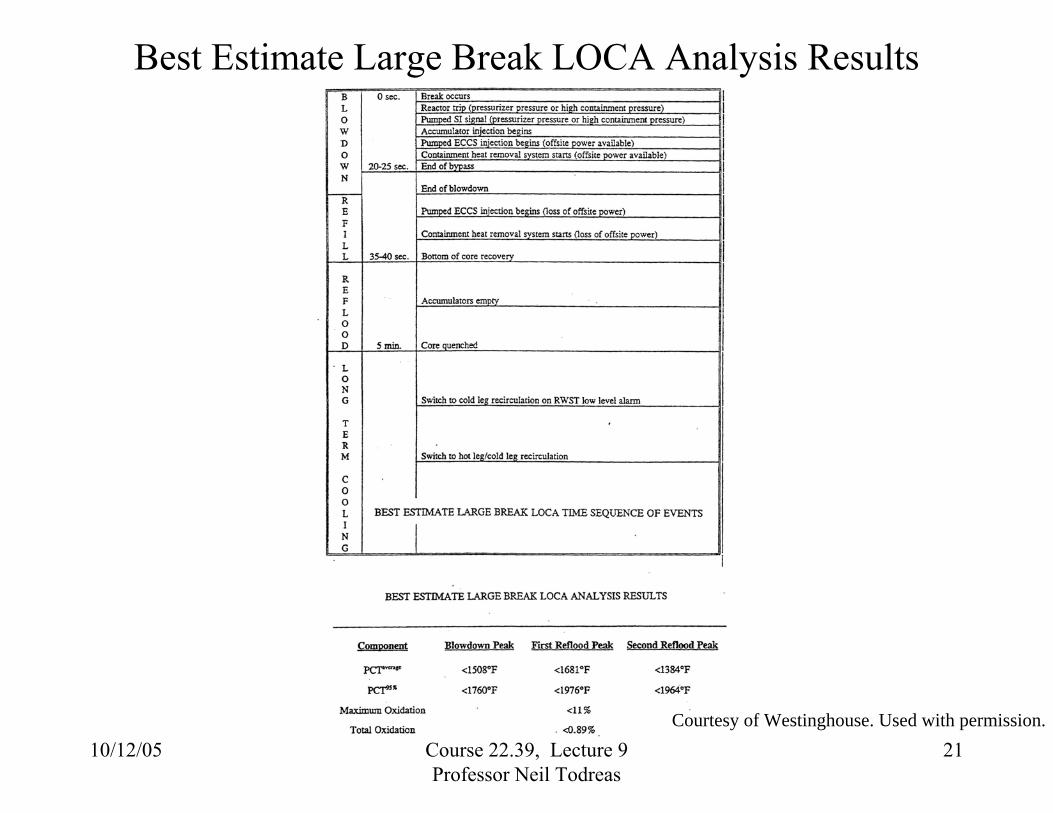
Best Estimate Large Break LOCA Analysis Results
10/12/05 Course 22.39, Lecture 9Professor Neil Todreas
21 Courtesy of Westinghouse. Used with permission.

South Texas FSAR Limiting Clad Temperature for LBLOCA
Source: Shuffler, C., J. Trant, N.E. Todreas, and A. Romano. Thermal Hydraulic and Economic Analysis of Grid-Supported, Hydride-Fueled PWRs (MIT-NFC-PR-077). Cambridge, MA: MIT CANES, January 2006.
10/12/05 Course 22.39, Lecture 9 Professor Neil Todreas
22

Source: Shuffler, C., J. Trant, N.E. Todreas, and A. Romano. Thermal Hydraulic and Economic Analysis of Grid-Supported, Hydride-Fueled PWRs (MIT-NFC-PR-077). Cambridge, MA: MIT CANES, January 2006.
10/12/05 Course 22.39, Lecture 9 Professor Neil Todreas
23

10/12/05 Course 22.39, Lecture 9 Professor Neil Todreas
24

Hole size to remove decay heat as steam
Figure removed for copyright reasons.Figure 4.12 in Collier, J. G., and G. F. Hewitt. Introduction to Nuclear Power.Washington, DC: Hemisphere Publishing, 1987.
10/12/05 Course 22.39, Lecture 9Professor Neil Todreas
25

Connection pipe diameter/cross section/percentage spectrum of a PWR. (Solid lines) Primary loop system;
(dashed lines) pressurizer
Figure removed for copyright reasons.Figure 4.21 in Collier, J. G., and G. F. Hewitt. Introduction to Nuclear Power.Washington, DC: Hemisphere Publishing, 1987.
10/12/05 Course 22.39, Lecture 9Professor Neil Todreas
26

Primary pressure vs time for small-break LOCAs in a PWR. ({) Primary temperature 175°C; (�) reflood tank empty.
(Two HPI pumps; reflood tanks 4 x 286 m3; no LPI pumps)
Figure removed for copyright reasons.Figure 4.22 in Collier, J. G., and G. F. Hewitt. Introduction to Nuclear Power.Washington, DC: Hemisphere Publishing, 1987.
10/12/05 Course 22.39, Lecture 9Professor Neil Todreas
27
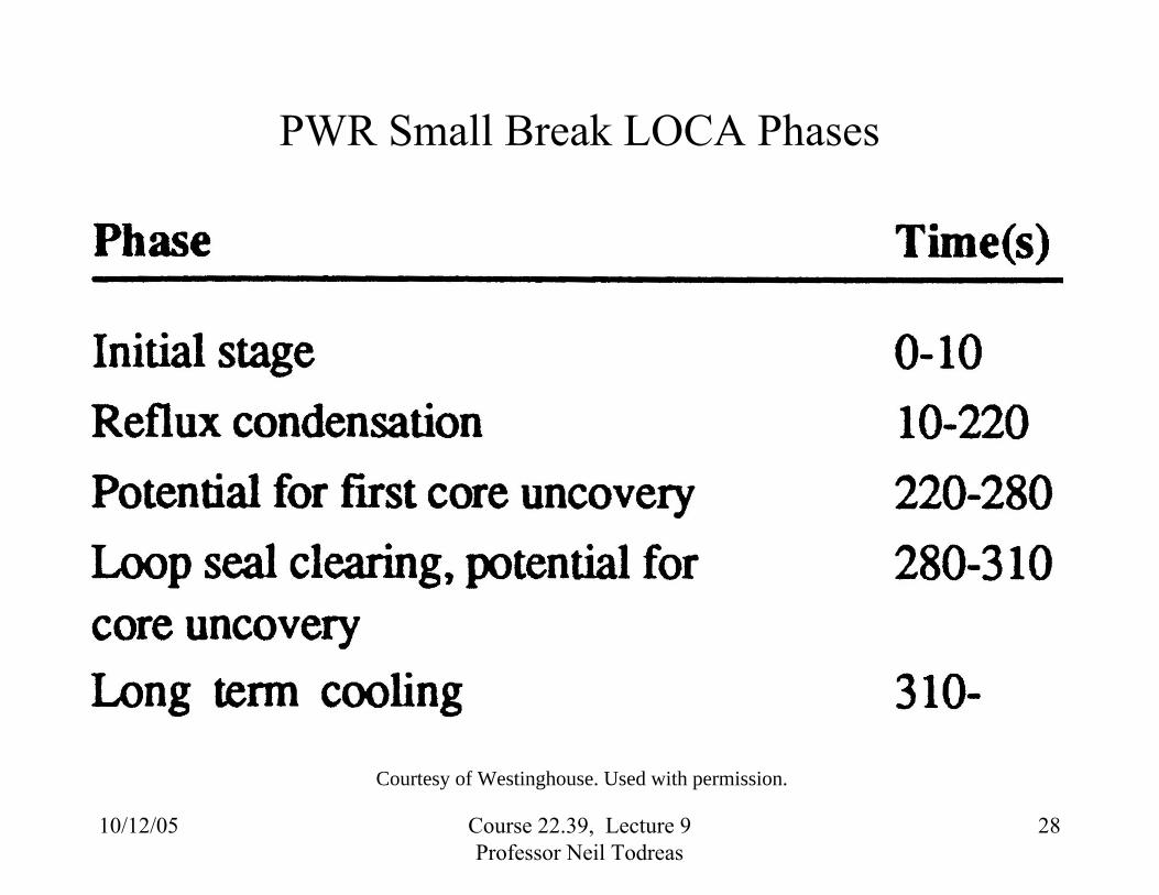
PWR Small Break LOCA Phases
10/12/05 Course 22.39, Lecture 9Professor Neil Todreas
28
Courtesy of Westinghouse. Used with permission.

Notrump Transient Results
10/12/05 Course 22.39, Lecture 9Professor Neil Todreas
29 Courtesy of Westinghouse. Used with permission.

Beginning of Life (BOL) Rod Heatup Results
10/12/05 Course 22.39, Lecture 9Professor Neil Todreas
30
Courtesy of Westinghouse. Used with permission.

![ANALISI DI UN INCIDENTE NON MITIGATO DI TIPO LOCA ...Coolant Accident (LOCA), con particolare riferimento al caso di un LBLOCA mitigato e non mitigato [4] [5]. Quest’ultimo scenario](https://img.dokumen.tips/doc/110x75/605156c79f819c67fd31a9d0/analisi-di-un-incidente-non-mitigato-di-tipo-loca-coolant-accident-loca-con.jpg)