Embed Size (px)
Citation preview


Los Angeles Manufacturing Facility
Houston, TX Manufacturing Facility Stockton, CA Distribution Facility
Schedule a plant tour of our 22 acre property in Los Angeles. Bring your customer or project and we’d be happy to take them around and show them the manufacturing process of their potential project. Contact your Hannibal sales rep for more information.
2/1/2016
Name Title Email Phone LineBlanton Bartlett President [email protected] 323.588.4261
Steve Rogers Executive Vice President [email protected] 323.588.4261Gary Steen Regional Sales Director(North&West) [email protected] 323.588.4261Ryan Peck Regional Sales Director(South&East) [email protected] 801.680.6373
Anna Coauette Regional Accounts Representative [email protected] 818.414.3555Nathan Sherwood Regional Accounts Representative [email protected] 480.215.4841
Josh Strickland Regional Accounts Representative [email protected] 817.584.1329Dean Bender Regional Accounts Representative [email protected] 209.481.7274
Francine Meehan Sales Supervisor [email protected] 323.588.4261Jennifer Feiock Office Manager (Stockton) [email protected] 209.948.8082Hilda Torres Sales Coordinator (Southeast) [email protected] 323.588.4261Mari Flores Account Manager [email protected] 323.588.4261
Willie Marquez Account Manager [email protected] 323.588.4261Daniel Tejeda Account Manager [email protected] 323.588.4261
Jared Meinecke Account Manager [email protected] 209-948-8082Carlos Vela Designer/Manager [email protected] 323.588.4261
Patrick Flores Designer [email protected] 323.588.4261Lynn Miller Designer (Stockton) [email protected] 209.948.8082
Fernando Garduno Designer [email protected] 323.588.4261David Castillejos Designer [email protected] 323.588.4261Fernando Rosillo Designer [email protected] 323.588.4261
Luis Zamora Designer [email protected] 323.588.4261John Ewing Operations Manager [email protected] 323.588.4261Jorge Rodas Production Master Scheduler [email protected] 323.588.4261
Sandy Mattey Logistics Manager [email protected] 323.588.4261Veronica Caldera Logistics Specialist [email protected] 323.588.4261MaryLou Quijano Credit Manager [email protected] 323.588.4261
Hannibal Company Directory

Part # Size Weight(EA)
IF1514 42x96 47
IF1514 42x120 61
IF3014 42x144 92
IF3014 42x192 124
IF3014 42x240 149
Part# Size Capacity Weight (EA)
I30140 96 3,191 24
I36140 96 5,254 28
I41140 108 4,826 32
I55140 144 6,490 51
I60130 144 8,284 66
Part# Size Weight (EA)
WFD4246 42x46 23
Part# Size Weight (EA)
AGBI-24 24" 11
RS 16-12 12" 2
FB3-42 42" 7
For L.A. Quick Ship questions contact:
P: (323) 588-4261 E: [email protected]
For Stockton Quick Ship questions contact:
P: (209)948-8082 E: [email protected]
L.A. & Stockton48 Hour Quick Ship

Roll-Formed Selective Pallet Rack is the most flexible and extensively used pallet rack in the material handling industry. We offer a wide variety of styles, sizes and gauges to meet most capacity and seismic requirements.
Features: Fast Clip Beam Attachment Compatible with Most Brands Welded Frame Design Cost Effective Flexible Applications High Quality Powder Coat Finish

1
1
2
1
1
2
1
4
I-SERIES FRAMES

"I" SeriesIF1514
Part# Depth Height Weight (EA)IF1514 3696 36" 96"/ 8' 45.90IF1514 4296 42" 96"/ 8' 47.80IF1514 4496 44" 96"/ 8' 48.40IF1514 4896 48" 96"/ 8' 50.00
Part# Depth Height Weight (EA)IF1514 36120 36" 120"/ 10' 58.50IF1514 42120 42" 120"/ 10' 60.00IF1514 44120 44" 120"/ 10' 61.10IF1514 48120 48" 120"/ 10' 64.50
Part# Depth Height Weight (EA)IF1514 36144 36" 144"/ 12' 65.60IF1514 42144 42" 144"/ 12' 68.50IF1514 44144 44" 144"/ 12' 69.30IF1514 48144 48" 144"/ 12' 71.60
Part# Depth Height Weight (EA)IF1514 36168 36" 168"/ 14' 79.40IF1514 42168 42" 168"/ 14' 83.00IF1514 44168 44" 168"/ 14' 83.90IF1514 48168 48" 168"/ 14' 87.00
Uprights
NON-STANDARD HEIGHTS MAY REQUIRE ADDITIONAL CHARGES. CONSULT FACTORY.
PRICE INCLUDES 3" x 4" x 3/16" - 2 HOLE FOOTPLATES
3" x 1-5/8" x 14 Ga
Value Beyond Expectations Page 5

"I" SeriesIF3014
Part# Depth Height Weight (EA)IF3014 3696 36" 96"/ 8' 64.50IF3014 4296 42" 96"/ 8' 65.70IF3014 4496 44" 96"/ 8' 66.40IF3014 4896 48" 96"/ 8' 67.90IF3014 5496 54" 96"/ 8' 70.20
Part# Depth Height Weight (EA)IF3014 36120 36" 120"/ 10' 79.90IF3014 42120 42" 120"/ 10' 78.60IF3014 44120 44" 120"/ 10' 82.70IF3014 48120 48" 120"/ 10' 84.70IF3014 54120 54" 120"/ 10' 88.10
Part# Depth Height Weight (EA)IF3014 36144 36" 144"/ 12' 89.90IF3014 42144 42" 144"/ 12' 91.50IF3014 44144 44" 144"/ 12' 92.70IF3014 48144 48" 144"/ 12' 95.70IF3014 54144 54" 144"/ 12' 98.10
Part# Depth Height Weight (EA)IF3014 36168 36" 168"/ 14' 106.50IF3014 42168 42" 168"/ 14' 108.70IF3014 44168 44" 168"/ 14' 110.10IF3014 48168 48" 168"/ 14' 109.30IF3014 54168 54" 168"/ 14' 112.00
Part# Depth Height Weight (EA)IF3014 36180 36" 180"/ 15' 111.00IF3014 42180 42" 180"/ 15' 115.00IF3014 44180 44" 180"/ 15' 116.10IF3014 48180 48" 180"/ 15' 118.90IF3014 54180 54" 180"/ 15' 122.20
Part# Depth Height Weight (EA)IF3014 36192 36" 192"/ 16' 119.10IF3014 42192 42" 192"/ 16' 122.90IF3014 44192 44" 192"/ 16' 124.30IF3014 48192 48" 192"/ 16' 127.30IF3014 54192 54" 192"/ 16' 131.90
Part# Depth Height Weight (EA)IF3014 36216 36" 216"/ 18' 133.20IF3014 42216 42" 216"/ 18' 135.80IF3014 44216 44" 216"/ 18' 137.50IF3014 48216 48" 216"/ 18' 140.70IF3014 54216 54" 216"/ 18' 145.00
Uprights 3" x 3" x 14 Ga
Page 6 Value Beyond Expectations

"I" Series UprightsIF3014
Part# Depth Height Weight (EA)IF3014 36240 36" 240"/20' 147.10IF3014 42240 42" 240"/20' 150.00IF3014 44240 44" 240"/20' 151.60IF3014 48240 48" 240"/20' 155.30IF3014 54240 54" 240"/20' 160.70
Part# Depth Height Weight (EA)IF3014 36264 36" 264"/22' 161.10IF3014 42264 42" 264"/22' 161.10IF3014 44264 44" 264"/22' 165.80IF3014 48264 48" 264"/22' 169.90IF3014 54264 54" 264"/22' 175.70
Part# Depth Height Weight (EA)IF3014 36288 36" 288"/24' 173.80IF3014 42288 42" 288"/24' 177.10IF3014 44288 44" 288"/24' 179.00IF3014 48288 48" 288"/24' 183.30IF3014 54288 54" 288"/24' 189.60
Part# Depth Height Weight (EA)IF3014 36300 36" 300"/25' 181.50IF3014 42300 42" 300"/25' 185.00IF3014 44300 44" 300"/25' 187.20IF3014 48300 48" 300"/25' 191.70IF3014 54300 54" 300"/25' 198.60
Part# Depth Height Weight (EA)IF3014 36324 36" 324"/27' 195.40IF3014 42324 42" 324"/27' 199.20IF3014 44324 44" 324"/27' 201.40IF3014 48324 48" 324"/27' 206.30IF3014 54324 54" 324"/27' 213.50
Part# Depth Height Weight (EA)IF3014 36360 36" 360"/30' 217.10IF3014 42360 42" 360"/30' 221.40IF3014 44360 44" 360"/30' 223.70IF3014 48360 48" 360"/30' 229.30IF3014 54360 54" 360"/30' 237.30
NON-STANDARD HEIGHTS MAY REQUIRE ADDITIONAL CHARGES. CONSULT FACTORY.PRICE INCLUDES 5" x 8" x 3/8" - 4 HOLE FOOTPLATES
3" x 3" x 14 Ga
Value Beyond Expectations Page 7

"I" Series UprightsIF3013
Part# Depth Height Weight (EA)IF3013 3696 36" 96"/ 8' 71.50IF3013 4296 42" 96"/ 8' 72.70IF3013 4496 44" 96"/ 8' 73.40IF3013 4896 48" 96"/ 8' 74.80IF3013 5496 54" 96"/ 8' 77.20
Part# Depth Height Weight (EA)IF3013 36120 36" 120"/ 10' 88.70IF3013 42120 42" 120"/ 10' 90.30IF3013 44120 44" 120"/ 10' 91.50IF3013 48120 48" 120"/ 10' 93.50IF3013 54120 54" 120"/ 10' 96.90
Part# Depth Height Weight (EA)IF3013 36144 36" 144"/ 12' 100.40IF3013 42144 42" 144"/ 12' 102.10IF3013 44144 44" 144"/ 12' 103.30IF3013 48144 48" 144"/ 12' 105.30IF3013 54144 54" 144"/12' 108.70
Part# Depth Height Weight (EA)IF3013 36168 36" 168"/ 14' 118.80IF3013 42168 42" 168"/ 14' 121.00IF3013 44168 44" 168"/ 14' 122.40IF3013 48168 48" 168"/ 14' 125.10IF3013 54168 54" 168"/ 14' 129.30
Part# Depth Height Weight (EA)IF3013 36180 36" 180"/ 15' 126.00IF3013 42180 42" 180"/ 15' 128.10IF3013 44180 44" 180"/ 15' 129.30IF3013 48180 48" 180"/ 15' 132.10IF3013 54180 54" 180"/ 15' 136.10
Part# Depth Height Weight (EA)IF3013 36192 36" 192"/ 16' 134.60IF3013 42192 42" 192"/ 16' 136.90IF3013 44192 44" 192"/ 16' 138.40IF3013 48192 48" 192"/ 16' 141.40IF3013 54192 54" 192"/ 16' 146.00
Part# Depth Height Weight (EA)IF3013 36216 36" 216"/ 18' 149.00IF3013 42216 42" 216"/ 18' 151.60IF3013 44216 44" 216"/ 18' 153.30IF3013 48216 48" 216"/ 18' 156.50IF3013 54216 54" 216"/ 18' 161.70
NON-STANDARD HEIGHTS MAY REQUIRE ADDITIONAL CHARGES. CONSULT FACTORY.
3" x 3" x 13 Ga
PRICE INCLUDES 5" x 8" x 3/8" - 4 HOLE FOOTPLATES
Page 8 Value Beyond Expectations

"I" Series UprightsIF3013
Part# Depth Height Weight (EA)IF3013 36240 36" 240"/ 20' 164.70IF3013 42240 42" 240"/ 20' 167.60IF3013 44240 44" 240"/ 20' 169.20IF3013 48240 48" 240"/ 20' 172.90IF3013 54240 54" 240"/ 20' 178.30
Part# Depth Height Weight (EA)IF3013 36264 36" 264"/ 22' 180.50IF3013 42264 42" 264"/ 22' 177.90IF3013 44264 44" 264"/ 22' 185.20IF3013 48264 48" 264"/ 22' 189.20IF3013 54264 54" 264"/ 22' 195.00
Part# Depth Height Weight (EA)IF3013 36288 36" 288"/ 24' 194.90IF3013 42288 42" 288"/ 24' 198.20IF3013 44288 44" 288"/ 24' 200.10IF3013 48288 48" 288"/ 24' 204.40IF3013 54288 54" 288"/ 24' 210.70
Part# Depth Height Weight (EA)IF3013 36300 36" 300"/ 25' 203.50IF3013 42300 42" 300"/ 25' 207.00IF3013 44300 44" 300"/ 25' 209.20IF3013 48300 48" 300"/ 25' 213.70IF3013 54300 54" 300"/ 25' 220.60
Part# Depth Height Weight (EA)IF3013 36324 36" 324"/27' 219.20IF3013 42324 42" 324"/27' 223.00IF3013 44324 44" 324"/27' 225.10IF3013 48324 48" 324"/27' 230.00IF3013 54324 54" 324"/27' 237.20
Part# Depth Height Weight (EA)IF3013 36360 36" 360"/30' 243.50IF3013 42360 42" 360"/30' 247.80IF3013 44360 44" 360"/30' 250.10IF3013 48360 48" 360"/30' 255.70IF3013 54360 54" 360"/30' 263.70
PRICE INCLUDES 5" x 8" x 3/8" - 4 HOLE FOOTPLATES NON-STANDARD HEIGHTS MAY REQUIRE ADDITIONAL CHARGES. CONSULT FACTORY.
3" x 3" x 13 Ga
Value Beyond Expectations Page 9

"I" Series UprightsIF3012
Part# Depth Height Weight (EA)IF3012 3696 36" 96"/ 8' 79.40IF3012 4296 42" 96"/ 8' 80.60IF3012 4496 44" 96"/ 8' 81.00IF3012 4896 48" 96"/ 8' 82.80IF3012 5496 54" 96"/ 8' 85.10
Part# Depth Height Weight (EA)
IF3012 36120 36" 120"/ 10' 98.50IF3012 42120 42" 120"/ 10' 100.10IF3012 44120 44" 120"/ 10' 101.30IF3012 48120 48" 120"/ 10' 103.30IF3012 54120 54" 120"/ 10' 106.70
Part# Depth Height Weight (EA)IF3012 36144 36" 144"/ 12' 112.20IF3012 42144 42" 144"/ 12' 113.90IF3012 44144 44" 144"/ 12' 115.00IF3012 48144 48" 144"/ 12' 117.00IF3012 54144 54" 144"/ 12' 120.40
Part# Depth Height Weight (EA)IF3012 36168 36" 168"/ 14' 130.70IF3012 42168 42" 168"/ 14' 134.50IF3012 44168 44" 168"/ 14' 136.10IF3012 48168 48" 168"/ 14' 138.70IF3012 54168 54" 168"/ 14' 143.00
Part# Depth Height Weight (EA)IF3012 36180 36" 180"/ 15' 140.70IF3012 42180 42" 180"/ 15' 142.80IF3012 44180 44" 180"/ 15' 144.00IF3012 48180 48" 180"/ 15' 146.80IF3012 54180 54" 180"/ 15' 150.80
Part# Depth Height Weight (EA)IF3012 36192 36" 192"/ 16' 150.20IF3012 42192 42" 192"/ 16' 152.60IF3012 44192 44" 192"/ 16' 154.00IF3012 48192 48" 192"/ 16' 157.10IF3012 54192 54" 192"/ 16' 161.60
Part# Depth Height Weight (EA)IF3012 36216 36" 216" / 18' 166.70IF3012 42216 42" 216" / 18' 169.30IF3012 44216 44" 216" / 18' 170.90IF3012 48216 48" 216" / 18' 174.20IF3012 54216 54" 216" / 18' 179.30
3" x 3" x 12 Ga
Page 10 Value Beyond Expectations

"I" SeriesIF3012
Part# Depth Height Weight (EA)IF3012 36240 36" 240"/ 20' 184.30IF3012 42240 42" 240"/ 20' 187.20IF3012 44240 44" 240"/ 20' 188.80IF3012 48240 48" 240"/ 20' 192.50IF3012 54240 54" 240"/ 20' 197.90
Part# Depth Height Weight (EA)IF3012 36264 36" 264"/ 22' 198.70IF3012 42264 42" 264"/ 22' 205.10IF3012 44264 44" 264"/ 22' 206.80IF3012 48264 48" 264"/ 22' 210.80IF3012 54264 54" 264"/ 22' 216.60
Part# Depth Height Weight (EA)IF3012 36288 36" 288"/ 24' 218.40IF3012 42288 42" 288"/ 24' 221.70IF3012 44288 44" 288"/ 24' 223.60IF3012 48288 48" 288"/ 24' 239.90IF3012 54288 54" 288"/ 24' 234.30
Part# Depth Height Weight (EA)IF3012 36300 36" 300"/ 25' 224.89IF3012 42300 42" 300"/ 25' 231.50IF3012 44300 44" 300"/ 25' 233.70IF3012 48300 48" 300"/ 25' 238.20IF3012 54300 54" 300"/ 25' 245.10
Part# Depth Height Weight (EA)IF3012 36324 36" 324"/ 27' 245.70IF3012 42324 42" 324"/ 27' 249.50IF3012 44324 44" 324"/ 27' 251.40IF3012 48324 48" 324"/ 27' 256.50IF3012 54324 54" 324"/ 27' 263.70
Part# Depth Height Weight (EA)IF3012 36360 36" 360"/ 30' 272.90IF3012 42360 42" 360"/ 30' 277.20IF3012 44360 44" 360"/ 30' 285.60IF3012 48360 48" 360"/ 30' 283.20IF3012 54360 54" 360"/ 30' 293.20
3" x 3" x 12 GaUprights
PRICE INCLUDES 5" x 8" x 3/8" - 4 HOLE FOOTPLATES
NON-STANDARD HEIGHTS MAY REQUIRE ADDITIONAL CHARGES. CONSULT FACTORY.
Value Beyond Expectations Paege 11

"I" Series UprightsIF3011
Part# Depth Height Weight (EA)IF3011 3696 36" 96"/ 8' 86.60IF3011 4296 42" 96"/ 8' 87.80IF3011 4496 44" 96"/ 8' 88.50IF3011 4896 48" 96"/ 8' 90.00IF3011 5496 54" 96"/ 8' 92.30
Part# Depth Height Weight (EA)IF3011 36120 36" 120"/ 10' 107.50IF3011 42120 42" 120"/ 10' 109.10IF3011 44120 44" 120"/ 10' 110.30IF3011 48120 48" 120"/ 10' 112.30IF3011 54120 54" 120"/ 10' 115.70
Part# Depth Height Weight (EA)IF3011 36144 36" 144"/ 12' 123.00IF3011 42144 42" 144"/ 12' 124.70IF3011 44144 44" 144"/ 12' 125.80IF3011 48144 48" 144"/ 12' 127.80IF3011 54144 54" 144"/ 12' 131.20
Part# Depth Height Weight (EA)IF3011 36168 36" 168"/ 14' 145.20IF3011 42168 42" 168"/ 14' 147.30IF3011 44168 44" 168"/ 14' 148.70IF3011 48168 48" 168"/ 14' 151.10IF3011 54168 54" 168"/ 14' 155.60
Part# Depth Height Weight (EA)IF3011 36180 36" 180"/ 15' 154.20IF3011 42180 42" 180"/ 15' 156.30IF3011 44180 44" 180"/ 15' 157.50IF3011 48180 48" 180"/ 15' 160.30IF3011 54180 54" 180"/ 15' 164.30
Part# Depth Height Weight (EA)IF3011 36192 36" 192"/ 16' 164.60IF3011 42192 42" 192"/ 16' 167.00IF3011 44192 44" 192"/ 16' 168.40IF3011 48192 48" 192"/ 16' 171.50IF3011 54192 54" 192"/ 16' 176.00
Part# Depth Height Weight (EA)IF3011 36216 36" 216"/ 18' 182.90IF3011 42216 42" 216"/ 18' 185.50IF3011 44216 44" 216"/ 18' 187.10IF3011 48216 48" 216"/ 18' 190.40IF3011 54216 54" 216"/ 18' 195.00
NON-STANDARD HEIGHTS MAY REQUIRE ADDITIONAL CHARGES. CONSULT FACTORY.
3" x 3" x 11 Ga
PRICE INCLUDES 5" x 8" x 3/8" - 4 HOLE FOOTPLATES
Page 12 Value Beyond Expectations

"I" Series UprightsIF3011
Part# Depth Height Weight (EA)IF3011 36240 36" 240"/ 20' 202.30IF3011 42240 42" 240"/ 20' 205.20IF3011 44240 44" 240"/ 20' 206.80IF3011 48240 48" 240"/ 20' 210.50IF3011 54240 54" 240"/ 20' 216.00
Part# Depth Height Weight (EA)IF3011 36264 36" 264"/ 22' 221.80IF3011 42264 42" 264"/ 22' 224.90IF3011 44264 44" 264"/ 22' 226.60IF3011 48264 48" 264"/ 22' 230.60IF3011 54264 54" 264"/ 22' 236.40
Part# Depth Height Weight (EA)IF3011 36288 36" 288"/ 24' 240.00IF3011 42288 42" 288"/ 24' 243.30IF3011 44288 44" 288"/ 24' 245.20IF3011 48288 48" 288"/ 24' 249.50IF3011 54288 54" 288"/ 24' 255.90
Part# Depth Height Weight (EA)IF3011 36300 36" 300"/ 25' 250.50IF3011 42300 42" 300"/ 25' 254.00IF3011 44300 44" 300"/ 25' 256.20IF3011 48300 48" 300"/ 25' 260.70IF3011 54300 54" 300"/ 25' 267.60
Part# Depth Height Weight (EA)IF3011 36324 36" 324"/ 27' 270.00IF3011 42324 42" 324"/ 27' 273.80IF3011 44324 44" 324"/ 27' 275.90IF3011 48324 48" 324"/ 27' 280.80IF3011 54324 54" 324"/ 27' 288.00
Part# Depth Height Weight (EA)IF3011 36360 36" 360"/ 30' 299.90IF3011 42360 42" 360"/ 30' 304.20IF3011 44360 44" 360"/ 30' 306.50IF3011 48360 48" 360"/ 30' 312.10IF3011 54360 54" 360"/ 30' 320.20
NON-STANDARD HEIGHTS MAY REQUIRE ADDITIONAL CHARGES. CONSULT FACTORY.PRICE INCLUDES 5" x 8" x 3/8" - 4 HOLE FOOTPLATES
3" x 3" x 11 Ga
Value Beyond Expectations Page 13


Single Columns Height Weight (EA)IC1514 96 96"/8' 17.70
IC1514 120 120"/10' 21.30IC1514 144 144"/12' 24.90IC1514 168 168"/14' 28.50
Single Columns Height Weight (EA)IC3014 96 96"/8' 24.30
IC3014 120 120"/10' 29.30IC3014 144 144"/12' 34.30IC3014 168 168"/14' 39.30IC3014 180 180"/15' 41.80IC3014 192 192"/16' 44.30IC3014 216 216"/18' 49.30IC3014 240 240"/20' 54.30IC3014 264 264"/22' 59.30IC3014 288 288"/24' 64.30IC3014 300 300"/25' 66.80IC3014 312 312"/26' 69.30IC3014 324 324"/27' 71.80IC3014 336 336"/28' 74.30IC3014 348 348"/29' 76.80IC3014 360 360"/30' 79.30
Single Columns Height Weight (EA)IC3013 96 96"/8' 27.80
IC3013 120 120"/10' 33.70IC3013 144 144"/12' 39.50IC3013 168 168"/14' 45.40IC3013 180 180"/15' 48.40IC3013 192 192"/16' 51.30IC3013 216 216"/18' 57.20IC3013 240 240"/20' 63.10IC3013 264 264"/22' 68.90IC3013 288 288"/24' 74.80IC3013 300 300"/25' 77.80IC3013 312 312"/26' 80.70IC3013 324 324"/27' 83.60IC3013 336 336"/28' 86.60IC3013 348 348"/29' 89.50IC3013 360 360"/30' 92.50
Columns"I" Series
PRICE INCLUDES 5" x 8" x 3/8" - 4 HOLE FOOTPLATES
IC1514 = 3" x 1 5/8" x 14 Ga.
IC3014 = 3" x 3" x 14 Ga.
IC3013 = 3" x 3" x 13 Ga.
PRICE INCLUDES 3" x 4" x 3/16" - 2 HOLE FOOTPLATES
PRICE INCLUDES 5" x 8" x 3/8" - 4 HOLE FOOTPLATES
Page 15 Value Beyond Expectations

"I" Series Columns
Single Columns Height Weight (EA)IC3012 96 96"/8' 31.70
IC3012 120 120"/10' 38.60IC3012 144 144"/12' 45.40IC3012 168 168"/14' 52.30IC3012 180 180"/15' 55.70IC3012 192 192"/16' 59.10IC3012 216 216"/18' 66.00IC3012 240 240"/20' 72.90IC3012 264 264"/22' 79.70IC3012 288 288"/24' 86.60IC3012 300 300"/25' 90.00IC3012 312 312"/26' 93.40IC3012 324 324"/27' 96.90IC3012 336 336"/28' 100.30IC3012 348 348"/29' 103.70IC3012 360 360"/30' 107.20
Single Columns Height Weight (EA)IC3011 96 96"/8' 35.30
IC3011 120 120"/10' 43.10IC3011 144 144"/12' 50.80IC3011 168 168"/14' 58.60IC3011 180 180"/15' 62.50IC3011 192 192"/16' 66.30IC3011 216 216"/18' 74.10IC3011 240 240"/20' 81.90IC3011 264 264"/22' 89.60IC3011 288 288"/24' 97.40IC3011 300 300"/25' 101.30IC3011 312 312"/26' 105.10IC3011 324 324"/27' 109.00IC3011 336 336"/28' 112.90IC3011 348 348"/29' 116.80IC3011 360 360"/30' 120.70
PRICE INCLUDES 5" x 8" x 3/8" - 4 HOLE FOOTPLATES
IC3012 = 3" x 3" x 12 Ga.
IC3011 = 3" x 3" x 11 Ga.
PRICE INCLUDES 5" x 8" x 3/8" - 4 HOLE FOOTPLATES
Value Beyond Expectations Page 16


"I" Series Beams14 Gauge
Part# Length Capacity Weight (EA)I24140 48 48" 6,176 12.56I24140 60 60" 5,152 15.01I24140 72 72" 4,141 17.46I24140 96 96" 2,534 22.36
I24140 108 108" 2,080 24.81I24140 120 120" 1,744 27.26
Part# Length Capacity Weight (EA)I30140 48 48" 7,618 13.60I30140 60 60" 6,284 16.31I30140 72 72" 5,392 19.02I30140 96 96" 3,453 24.44
I30140 108 108" 2,814 27.15I30140 120 120" 2,347 29.86
Part# Length Capacity Weight (EA)I33140 60 60" 7,250 17.26I33140 72 72" 6,192 20.16I33140 96 96" 4,304 25.96
I33140 108 108" 3,487 28.86I33140 120 120" 2,898 31.76I33140 144 144" 2,107 37.56
Part# Length Capacity Weight (EA)I36140 60 60" 8,303 18.31I36140 72 72" 7,062 21.42I36140 96 96" 5,299 27.64
I36140 108 108" 4,282 30.75I36140 120 120" 3,545 33.86I36140 144 144" 2,560 40.08
STEP BEAM 2-1/2" FACE X 1-5/8" STEP 14 GA
CAP LOCK 4 PIN = $7.50 (add to list price)
STEP BEAM 3-3/4" FACE X 1-5/8" STEP 14 GA
STEP BEAM 3" FACE X 1-5/8" STEP 14 GA
STEP BEAM 3-3/8" FACE X 1-5/8" STEP 14 GA
NON-STANDARD LENGTHS MAY REQUIRE ADDITIONAL CHARGES. CONSULT FACTORY.
CAP LOCK 3 PIN = $2.00 (add to list price)4 PIN CONNECTOR = $5.50/beam (add to list price)
Page 18 Value Beyond Expectations

"I" Series Beams14 Gauge
Part# Length Capacity Weight (EA)I41140-60 60" 9,441 19.16I41140-72 72" 7,999 22.44I41140-96 96" 6,193 29.00
I41140-108 108" 5,207 32.28I41140-120 120" 4,290 35.56I41140-144 144" 3,086 42.12
Part# Length Capacity Weight (EA)I44140-72 72" 9,015 23.58I44140-96 96" 6,444 30.52
I44140-108 108" 6,249 33.99I44140-120 120" 5,155 37.46I44140-144 144" 3,685 44.40
Part# Length Capacity Weight (EA)I50140-72 72" 10,463 25.14I50140-96 96" 8,011 32.60
I50140-108 108" 7,200 36.33I50140-120 120" 6,491 40.06I50140-144 144" 4,613 47.52
Part# Length Capacity Weight (EA)I55140-72 72" 12,420 27.00I55140-96 96" 9,475 35.08
I55140-108 108" 8,486 39.12I55140-120 120" 7,704 43.16I55140-144 144" 6,004 51.24
Part# Length Capacity Weight (EA)*I60130-96 96" 12,526 44.08
*I60130-108 108 11,193 49.13*I60130-120 120" 10,138 54.18*I60130-144 144" 8,204 64.28
STEP BEAM 4-1/8" FACE X 1-5/8" STEP 14 GA
* C6 CONNECTOR IS STANDARD
CAP LOCK 4 PIN = $7.50 (add to list price)
STEP BEAM 6" FACE X 1-5/8" STEP 13 GA
STEP BEAM 4-1/2" FACE X 1-5/8" STEP 14 GA
STEP BEAM 5" FACE X 1-5/8" STEP 14 GA
STEP BEAM 5-5/8" FACE X 1-5/8" STEP 14 GA
NON-STANDARD LENGTHS MAY REQUIRE ADDITIONAL CHARGES. CONSULT FACTORY.
CAP LOCK 3 PIN = $2.00 (add to list price)4 PIN CONNECTOR = $5.50/beam (add to list price)
Value Beyond Expectations Page 19
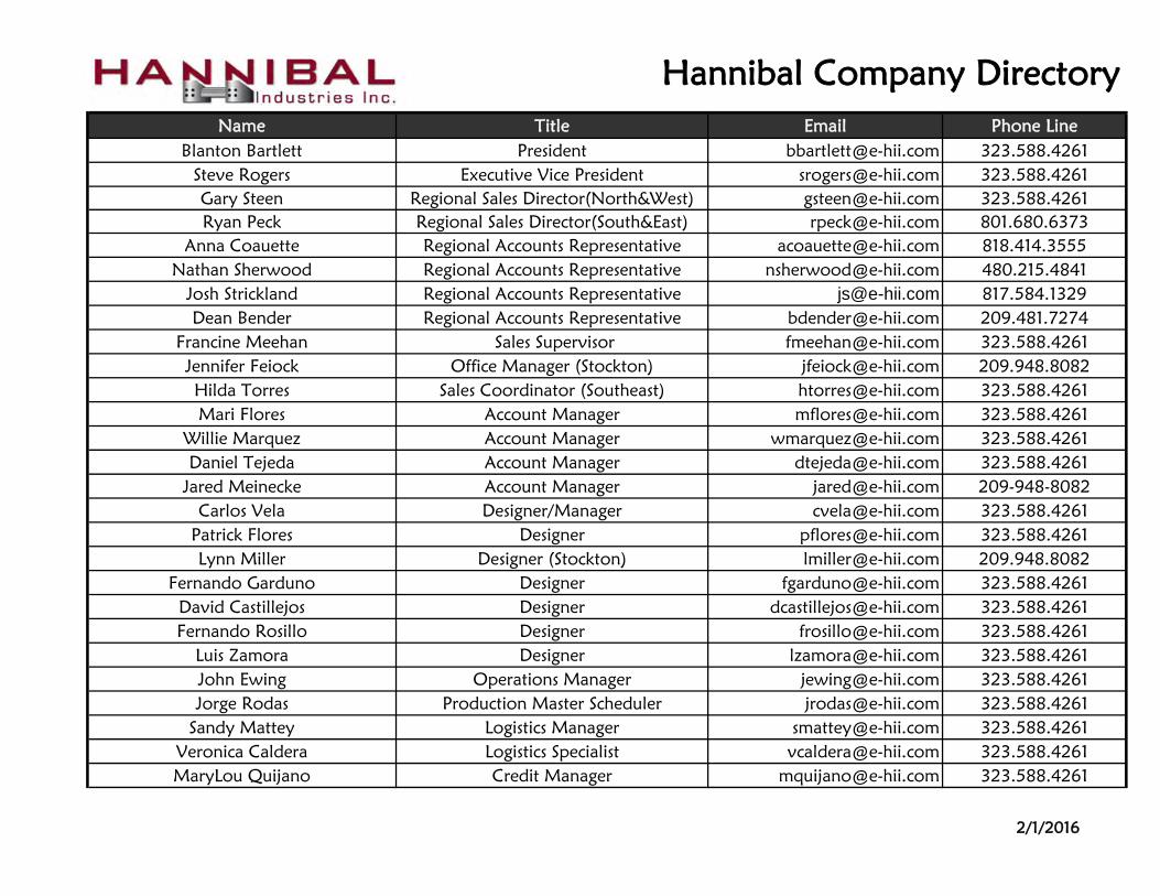
"I" Series BeamsSTEP BEAM 2-1/2" FACE X 1-5/8" STEP 16 GA
Part# Length Capacity Weight (EA)I24160 48 48" 5,157 10.70I24160 60 60" 4,320 12.70I24160 72 72" 3,585 14.60I24160 96 96" 2,212 18.60
I24160 108 108" 1,818 20.60I24160 120 120" 1,528 22.60
Part# Length Capacity Weight (EA)I30160 48 48" 6,284 11.52I30160 60 60" 5,208 13.71I30160 72 72" 4,485 15.90I30160 96 96" 2,968 20.28
I30160 108 108" 2,427 22.47I30160 120 120" 2,030 24.66
Part# Length Capacity Weight (EA)I33160 60 60" 5,970 14.46I33160 72 72" 5,114 16.80I33160 96 96" 3,664 21.48
I33160 108 108" 2,980 23.82I33160 120 120" 2,484 26.16
Part# Length Capacity Weight (EA)I36160 60 60" 6,797 15.21I36160 72 72" 5,797 17.70I36160 96 96" 4,476 22.68
I36160 108 108" 3,630 25.17I36160 120 120" 3,011 27.66
Part# Length Capacity Weight (EA)I41160 60 60" 7,689 16.01I41160 72 72" 6,532 18.66I41160 96 96" 5,085 23.96
I41160 108 108" 4,378 26.61I41160 120 120" 3,618 29.26
Part# Length Capacity Weight (EA)I44160 72 72" 7,327 19.56I44160 96 96" 5,666 25.16
I44160 108 108" 5,113 27.96I44160 120 120" 4,315 30.76
CAP LOCK 4 PIN = $7.50 (add to list price)
STEP BEAM 4-1/8" FACE X 1-5/8" STEP 16 GA
STEP BEAM 4-1/2" FACE X 1-5/8" STEP 16 GA
STEP BEAM 3" FACE X 1-5/8" STEP 16 GA
STEP BEAM 3-3/8" FACE X 1-5/8" STEP 16 GA
STEP BEAM 3-3/4" FACE X 1-5/8" STEP 16 GA
NON-STANDARD LENGTHS MAY REQUIRE ADDITIONAL CHARGES. CONSULT FACTORY.
CAP LOCK 3 PIN = $2.00 (add to list price)4 PIN CONNECTOR = $5.50/beam (add to list price)
Page 20 Value Beyond Expectations


"I" Series
Part# Size Weight (EA)FP18734 3" x 4" X 3/16" 0.60FP37558 5" X 8" X 3/8" 4.30FP37588 8" X 8 " X 3/8" 6.80
Part# Size Weight (EA)RS 6 6" 1.10
RS 12 12" 1.90RS 18 18" 2.70RS 24 24" 3.40RS 36 36" 5.00RS 48 48" 6.50RS 60 60" 8.00RS 72 72" 9.60
Part# Size Weight (EA)AGBI24 24" 10.30AGBI36 36" 17.40AGBI48 48" 20.60
Part# Size Weight (EA)AGBI24-FP 24" 12.00AGBI36-FP 36" 19.10AGBI48-FP 48" 22.30
Part# Size Weight (EA)SH16G58 5" x 8" 16ga 0.70SH16G88 8" x 8" 16ga 1.10SH11G58 5" x 8" 11ga 1.40SH11G88 8" x 8" 11ga 2.20
Part# Size Weight (EA)WA450TZ 1/2" X 4.50" 0.30WA550TZ 1/2" X 5.50" 0.32
Frame Accessories
4 Hole Footplates
Galvanized Positive Row Spacers
Column Guards - Bolt On Apex without Footplate
Column Guards - Bolt On Apex with Footplate 2" x 6" x 1/2"
Galvanized Shims
Anchors
Value Beyond Expectations Page 22

"I" SeriesPowder-Coat Front to Back Formed 3" x 3/4" x length
Part# Length Weight (EA)FB1-36 36" 3.80FB1-42 42" 4.50FB1-44 44" 4.70FB1-48 48" 5.20
Part# Length Weight (EA)FB3-36 36" 4.98FB3-42 42" 5.90FB3-44 44" 6.20FB3-48 48" 6.82
Part# Length Weight (EA)HAT-14 36" 4.40HAT-14 42" 5.10HAT-14 44" 5.40HAT-14 48" 5.90HAT-14 54" 6.60
Beam Accessories
Galvanized 3" X 1 5/8" X Length overlap
Galvanized Hat Section 14 Ga
Page 23 Value Beyond Expectations

Tube Rack
The Hannibal Patent Pending TubeRack system provides a stronger, safer and smarter alternative to conventional racking systems
TubeRack can be used for all our storage solutions such as Selective, Double Deep, Push Back, Drive-In, Archive, Retail, and AS/RS systems.
Features and Benefits: More capacity in both seismic and non-seismic zones
Impact Resistant Reduces product shedding in the case of impact or seismic events Better tolerances and easy to splice Superior solution for inferior building slabs 1” Beam Adjustability Lower Freight Costs Modular design allows future flexibility High Quality Powder Coated Finish
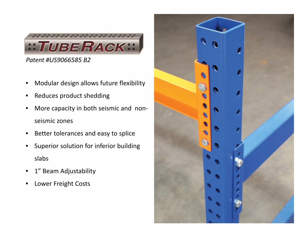
• Modular design allows future flexibility
• Reduces product shedding
• More capacity in both seismic and non‐
seismic zones
• Better tolerances and easy to splice
• Superior solution for inferior building
slabs
• 1” Beam Adjustability
• Lower Freight Costs
Patent #US9066585 B2

Stronger, Safer, Smarter
TubeRack Impact Test Video
Hannibal Industries’ TUBE RACK tm is a brand new approach to racking, offering the best of all existing rack structures rolled into to one
fresh and innovative solution.
Hannibal’s PATENT PENDING engineered solution provides dual moment resistance in both down aisle as well as cross aisle direction. This
engineering breakthrough results in as much as 50% reduction in uplift on the footplate to slab calculation, significantly lessoning slab uplift
design requirements in all facilities, including installations open to the general public.
STRENGTH to Weight- TUBE RACK’s A500 Grade-B structural tubing design utilizes the same structural tubing used in building columns and
bridges.
STRAIGTNESS- Structural tubing provides up to TWICE the straightness tolerances of structural channel as defined by ASTM specifications.
MODULAR DESIGN- TUBE RACK provides a modular design making racking configuration changes or repair simple and extremely cost
effective. Both height and depth of the design can be altered affordably and with little effect on ongoing operations.
SHIPPING COSTS- TUBE RACK allows for maximum weight over cube, providing an average 35% savings in shipping costs.
IMPACT RESISTANCE- Hannibal’s TUBE RACK offers up to ¼” thick welded shapes with dimensions up to 4”x 4” providing the highest impact
resistance in the business.
FIT and FINISH- Hannibal’s TUBE RACK provides for smooth and flat surfaces allowing significantly superior powder coat coverage with little
or no mill scale chipping. This system simply looks good.
SAFETY ABOVE ALL- TUBE RACK provides the safest working and shopping conditions for your employees and customers. Our design
significantly lowers the potential of product shed in a seismic or impact event. The ½”, Grade 5, bolted connections eliminate the potential
of a broken horizontal or diagonal brace going undetected in a typical existing racking system. This safety benefit of Hannibal’s TUBE RACK
is the one of which we are most proud to bring to our market.

Features & Benefits• More Capacity in both seismic and non‐seismic zones
• Impact resistant
• Reduces product shedding in the case of impact or seismic events
• Better tolerances and easy to splice
• Superior solution for inferior building slabs
• 1” Beam Adjustability
• Lower Freight Costs
• Modular design allows future flexibility

Applications Selective Drive-In
Pushback Pallet Flow
Pic Modules

Selective


Pic Modules


Common TubeRack Footplates


TubeRack®
A Revolution
in Steel Pallet
Storage Rack Systems
A White Paper

2
The Problem
When iconic pop singer Carole King
wrote and sang the lyrics “I feel the
earth move under my feet” she was crooning a love song. Little did she
know how those words would shake
up business and industry leaders
worldwide, especially in earthquake
prone areas like California and the Pacific Rim, South America, Japan
and Southeast Asia, for instance.
According to seismic engineers at the Jet Propulsion Laboratory in Pasadena, “recent
earthquakes (Northridge, Calif. 1994, 6.7 on the Richter Scale and the Kobe, Japan
quake of 6.9) demonstrated the risks to modern industrial societies facing the real
possibilities for massive loss of life, infra-structure damage and financial instability.”
While major efforts have been made to im-prove safety procedures, develop new
technologies and implement stricter build ing codes in the U.S., there still remains a
strong need to shore up earthquake resis-tance of a building’s contents which can be
displaced if not securely designed, in-stalled, maintained and loaded.
For low-profile objects that slide, shake
damage can be minimal, but loss can in-crease when equipment must be realigned
or interconnections repaired. Some sus-
pended items may swing without conse-quences, while others may sustain sub-
stantial damage from broken connections, impact with other objects or loss of vertical
support. Objects with relatively high cen-ters of gravity can collapse or overturn.
This danger is most evident in consumer
warehouses or “big box” stores, such as Home Depot, Costco and others, and in in-
dustrial buildings that store products and parts for manufacturing and shipping.
These facilities currently use tall metal storage racks to hold standard forklift-
ready pallets loaded with objects typically
weighing thousands of pounds, ie: vehicle

3
engines, heavy machinery, appliances.
With the advent of large forklifts capable of
raising pallets to heights of 24-feet and higher, the racks are vulnerable to sway-
ing, collapsing or toppling during an earth-quake -- a scenario for disaster.
For 35 years, the technology for manufac-
turing storage racks has not changed. Steve Rogers, vice president of sales for
Hannibal Industries in Los Angeles, one of
the country’s leading rack manufacturers,
explained that not only is seismic activity a cause for concern among his customers,
the costs and logistics of shipping, assem-bling and reassembling the rack configura-
tions also play an important role in the purchasing decisions.
He added that, depending on the height
and configuration of the racks, combined with the expected weight of the stored
items, his customers may need to increase

4
the thickness and strength of the concrete
slab they are anchored to, a major ex-pense that can cost millions of dollars.
Hannibal and other storage rack manufac-
turers adhere to structural code guidelines established in the last decade by a special
Rack Project Task Group formed at the re-quest of the Federal Emergency Manage-
ment Agency (FEMA) by the Building Seis-mic Safety Council (BSSC). The group is
comprised of engineers, storage rack de-signers, researchers, members of the Rack
Manufacturers Institute (RMI) and the Re
tail Industry Leaders Association, and other
experts.
Until now, said Rogers, there have been two major types of racking:
One is the traditional “roll-formed” rack,
which typically utilizes an open C-section column of varying shapes depending on
the manufacturer. Traditionally in the U.S., with this particular product a brace is
welded into the section, becoming a welded truss, horizontally and diagonally.
Some companies in both Europe and Amer-ica bolt the brace into the column instead
of welding it for two main advantages – to
save manufacturing costs and reduce ship-ping costs by compacting the load. The
disadvantage of manual assembly is that the welding costs are transferred to the
costs of installation, which involves labor and sorting the many boxes of nuts and
bolts at the jobsite.
The other type of rack is “structural”. The manufacturing starts with hot-formed
structural angle and channel steel which is then cut, hole-punched, welded and
painted to the customer’s specifications. Some companies make either the C-section
or the structural racks. Hannibal makes
both types to satisfy any need their cus-tomers might have, said Rogers.
However, as the customers require higher
and stronger rack configurations to bear the weight of heavier pallets (the average
pallet handles 2500 pounds and is ex-pected to reach 3500 pounds in the imme-

5
diate future), Rogers also recognized their
fears of possible dire consequences from earthquakes, seismic movement and in-
dustrial accidents.
“What is happening with existing rack sys-
tems,” said Rogers, “is the footprints are
getting bigger, often forcing the customer to build thicker slabs. Ten years ago the
standard concrete floor was 5-6 inches thick. Today, the customers want to go
35 feet high and store 3000-pound pallets. Under most building codes, the facilities
must have 10-inch thick slabs to withstand
that kind of seismic stress. As the codes become more stringent, getting that high
with that kind of load is not an option – even with a 10-inch slab.”
How could customers meet their demands
without the tremendous expense of retro-fitting their expansive slabs or face code
violations?
The Solution
In 2005, the Federal Emergency
Management Agency (FEMA), acting
under the National Earthquake Haz-
ards Reduction Program (NEHRP), is-
sued a 160-page report specifying recommendations for improvements
to buildings and their contents, in-
cluding steel pallet storage racks lo-
cated in areas accessible to the pub-
lic and to employees. The report is designated as a “voluntary resource
document” for use by practicing de-
sign professionals and building offi-
cials, and serves as the basis for the seismic requirements of the nation’s
model building codes and standards.
In developing the report a FEMA task force focused primarily on steel single selective
pallet storage racks. It reviewed available information on storage rack performance
during earthquakes and the background on the development of standards and code re-
quirements for storage racks. It also as-
sessed seismic requirements for storage racks and current practices with respect to
rack design, maintenance and operations, quality assurance and post-earthquake in-
spections, and it examined available re-search and testing data.
As a result, the task force recommended
specific design principals and cyclic con-nection testing that would enhance already

6
existing methods of collapse prevention. It
found that the rigid behavior of rack struc-tural system members and connections are
“significantly different from those of build-ing structural systems (although the sys-
tems appear physically similar) and stor-age racks do not have the added benefit of
diaphragms or secondary structural ele-ments found in building structures.”
Because the detailed behavior of rack con-
nections can be so fundamentally different from those used in buildings, the report
states, “it is recommended that typical building system type detailing approaches
not be applied to racks. Instead, the ap-
proaches should consider the nonlinear be-havior of the racks and the necessary de-
tailing that will ensure that the seismic re-sponse will be acceptable.”
Enter the TubeRack
from Hannibal Industries
Fortunately, Hannibal’s long-time en-
gineering consultant, Andrew Kirby,
had the seismic danger problem on his mind for several years. He was
familiar with the FEMA report as well
as state and municipal code require-
ments as they applied to steel pallet
storage racks, and had developed a new patent-pending rack design that
would satisfy and surpass federal
recommendations and meet all exist-
ing standards.
Kirby saw Hannibal as a perfect fit for his new design because it is a leading rack
manufacturer with the capability to pro-
duce the tubular steel frames required. After working with Hannibal’s designers
and submitting a pending joint-ownership patent, Kirby’s idea is now reality under
the brand name TubeRack.
“TubeRack is simplistic in design,” said Kirby, “with unique structural engineering
features and advantages not found in pre- vious large and tall metal storage racks
used inside or outside buildings. Each rack’s flexible moment frame can flex or
drift laterally during an earthquake, reduc-ing the potential of the frame collapsing
and damage to stored goods and greatly
improving safety to persons in the area

7
next to the frame.”
TubeRack advantages:
• Field assembly can be accom-
plished without welding through the use of hand-ratcheted “snug
tight” nuts and bolts. Accord-ing to Kirby, “...all bolts are
tightened sufficiently to prevent removal of the nuts without the
use of a wrench. With Tube-Rack installations, all connection
bolts are visible. However, for ‘hot-rolled’ racks the bolt nuts
are hidden behind the flanges of
the posts and any loose nuts are more likely to go un-
noticed.”
• TubeRacks are modular and scalable — all frame compo-
nents are interchangeable and can be built to various heights.
The length and width of the racks can be easily increased
when additional storage is re-quired.
• The TubeRack’s simplistic de-
sign uses standard, angular
shaped, hollow metal posts with less frame weight, increased
flexibility and decreased costs.
• TubeRack provides a “flexible moment frame” that allows
access for loaded pallets and flexes or “floats” in a lateral
motion during seismic activity in all
directions.
• Due to their unique design and construction, TubeRacks can be
mounted on existing slabs and provide greater storage capacity
than conventional racks.
• Using TubeRack’s higher capac-ity pallet loads, up to 3,500
pounds can be easily and safely accommodated in Hannibal’s
various storage solutions – Selective, Double Deep, Push
Back, Pallet Flow, Drive-in,
Archive, Retail and AS/RS Sys- tems.
“Instead of welding or
bolting a solid truss, Kirby’s design allows us to
create a system with only horizontal members, no
diagonals and connections that use snug tightened
bolts, not ratcheted,” Rogers added.
“The footplates are smaller and the anchor
bolts are closer to the column, not further
away. This allows movement in all direc-tions to relieve the stress during a seismic
event.” Kirby calls it a “horizontal spring”, the energy goes into the structure and re-
turns to its original position. This combi-nation of strength, flexibility, ease of in-
stallation and reassembly is ideal
8
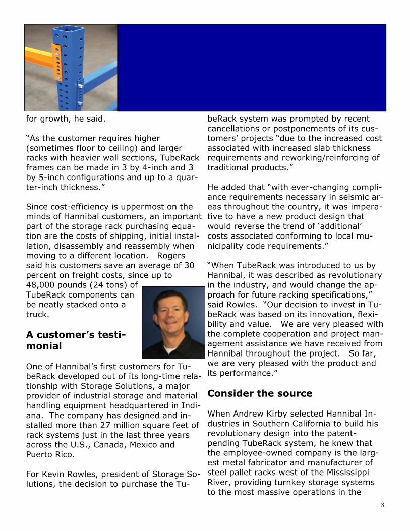
for growth, he said.
“As the customer requires higher
(sometimes floor to ceiling) and larger racks with heavier wall sections, TubeRack
frames can be made in 3 by 4-inch and 3 by 5-inch configurations and up to a quar-
ter-inch thickness.”
Since cost-efficiency is uppermost on the minds of Hannibal customers, an important
part of the storage rack purchasing equa-tion are the costs of shipping, initial instal-
lation, disassembly and reassembly when moving to a different location. Rogers
said his customers save an average of 30
percent on freight costs, since up to 48,000 pounds (24 tons) of
TubeRack components can be neatly stacked onto a
truck.
A customer’s testi-monial
One of Hannibal’s first customers for Tu-beRack developed out of its long-time rela-
tionship with Storage Solutions, a major provider of industrial storage and material
handling equipment headquartered in Indi-
ana. The company has designed and in-stalled more than 27 million square feet of
rack systems just in the last three years across the U.S., Canada, Mexico and
Puerto Rico.
For Kevin Rowles, president of Storage So-lutions, the decision to purchase the Tu-
beRack system was prompted by recent
cancellations or postponements of its cus-tomers’ projects “due to the increased cost
associated with increased slab thickness requirements and reworking/reinforcing of
traditional products.”
He added that “with ever-changing compli-ance requirements necessary in seismic ar-
eas throughout the country, it was impera-tive to have a new product design that
would reverse the trend of ‘additional’ costs associated conforming to local mu-
nicipality code requirements.”
“When TubeRack was introduced to us by
Hannibal, it was described as revolutionary in the industry, and would change the ap-
proach for future racking specifications,” said Rowles. “Our decision to invest in Tu-
beRack was based on its innovation, flexi-bility and value. We are very pleased with
the complete cooperation and project man-agement assistance we have received from
Hannibal throughout the project. So far, we are very pleased with the product and
its performance.”
Consider the source When Andrew Kirby selected Hannibal In-
dustries in Southern California to build his revolutionary design into the patent-
pending TubeRack system, he knew that the employee-owned company is the larg-
est metal fabricator and manufacturer of steel pallet racks west of the Mississippi
River, providing turnkey storage systems
to the most massive operations in the

9
world. Its customers include “big box” re-tailers, archive storage and food and bev-
erage industries.
During his long relationship as an engi-neering consultant to Hannibal, he also
knew that the company is committed to quality throughout its diverse product line,
including safety and code compliance (the tubular products division is ISO 9000-2008
certified). And he was impressed with the fact that Hannibal already owned a patent
for a pallet rack system adjustable safety restraint.
In its two divisions, headquartered near
central Los Angeles at 3851 Santa Fe Ave.,
Hannibal’s high value steel products are offered in round, square, rectangular and
other shapes (oval, elliptical, trapezoid) will wall thicknesses ranging from .035-
inch to .250-inch, and with hot-rolled, pickled and oiled, cold rolled, galvanized
and aluminized surface finishes.
With its TubeRack systems, Hannibal’s product line consists of structural and roll-
formed pallet racks and a variety of rack systems, including Hybrid, Cantilever,
Pushback, Pallet Flow, Case Flow and Drive-in.
Hannibal customers also can take advan-
tage of Hannibal’s engineering and design services which include system design, seis-
mic engineering, permit administration, in-house installation and custom fabrication.
Contact Information
More information about Hannibal’s new TubeRack systems and its wide variety of
steel storage rack systems and services is available at the company website,
www.hannibalrack.com, or by calling cor-porate headquarters at toll-free 1-866-513
-1200.
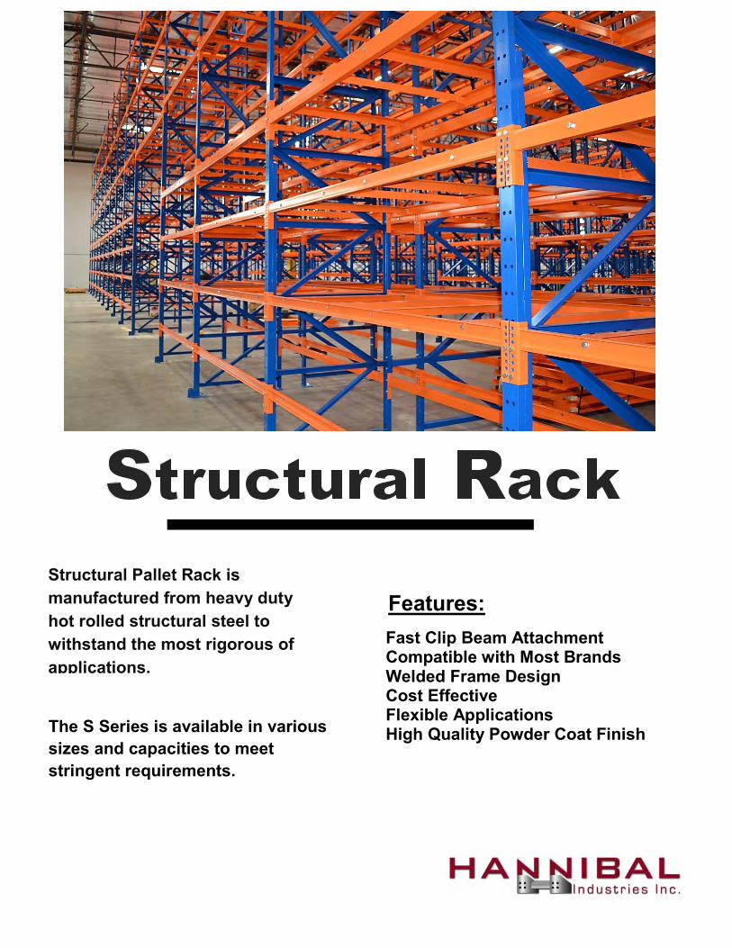
Structural Pallet Rack is manufactured from heavy duty hot rolled structural steel to withstand the most rigorous of applications.
The S Series is available in various sizes and capacities to meet stringent requirements.
Features:
Fast Clip Beam Attachment Compatible with Most Brands Welded Frame Design Cost Effective Flexible Applications High Quality Powder Coat Finish


Structural50KSI
Part# Depth Height Weight (EA)SF3135 36" 96" / 8' 85.90SF3135 42" 96" / 8' 88.50SF3135 44" 96" / 8' 89.40SF3135 48" 96" / 8' 91.20
Part# Depth Height Weight (EA)SF3135 36" 108" / 9' 96.50SF3135 42" 108" / 9' 99.80SF3135 44" 108" / 9' 100.80SF3135 48" 108" / 9' 103.10
Part# Depth Height Weight (EA)SF3135 36" 120"/ 10' 107.10SF3135 42" 120"/ 10' 111.00SF3135 44" 120"/ 10' 112.30SF3135 48" 120"/ 10' 114.90
Part# Depth Height Weight (EA)SF3135 36" 132" / 11' 114.10SF3135 42" 132" / 11' 118.00SF3135 44" 132" / 11' 119.30SF3135 48" 132" / 11' 121.90
Part# Depth Height Weight (EA)SF3135 36" 144" / 12' 122.70SF3135 42" 144" / 12' 126.40SF3135 44" 144" / 12' 127.60SF3135 48" 144" / 12' 130.10
Part# Depth Height Weight (EA)SF3135 36" 156"/ 13' 133.40SF3135 42" 156"/ 13' 137.70SF3135 44" 156"/ 13' 139.00SF3135 48" 156"/ 13' 142.00
Part# Depth Height Weight (EA)SF3135 36" 168"/ 14' 144.00SF3135 42" 168"/ 14' 148.90SF3135 44" 168"/ 14' 150.50SF3135 48" 168"/ 14' 144.10
C3 x 3.5# Per Ft
NON-STANDARD HEIGHTS REQUIRE ADDITIONAL CHARGES. CONSULT FACTORY.
1-1/2" x 1-1/2" x 1/8" Bracing
INCLUDES STANDARD 5" x 8" x 3/8" FOOTPLATE
Uprights
Page 27 Value Beyond Expectations
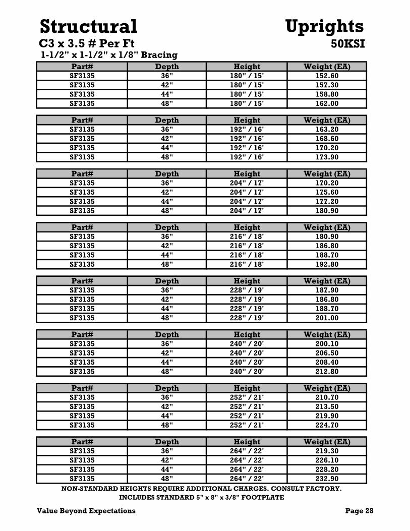
Structural 50KSI
Part# Depth Height Weight (EA)SF3135 36" 180" / 15' 152.60SF3135 42" 180" / 15' 157.30SF3135 44" 180" / 15' 158.80SF3135 48" 180" / 15' 162.00
Part# Depth Height Weight (EA)SF3135 36" 192" / 16' 163.20SF3135 42" 192" / 16' 168.60SF3135 44" 192" / 16' 170.20SF3135 48" 192" / 16' 173.90
Part# Depth Height Weight (EA)SF3135 36" 204" / 17' 170.20SF3135 42" 204" / 17' 175.60SF3135 44" 204" / 17' 177.20SF3135 48" 204" / 17' 180.90
Part# Depth Height Weight (EA)SF3135 36" 216" / 18' 180.90SF3135 42" 216" / 18' 186.80SF3135 44" 216" / 18' 188.70SF3135 48" 216" / 18' 192.80
Part# Depth Height Weight (EA)SF3135 36" 228" / 19' 187.90SF3135 42" 228" / 19' 186.80SF3135 44" 228" / 19' 188.70SF3135 48" 228" / 19' 201.00
Part# Depth Height Weight (EA)SF3135 36" 240" / 20' 200.10SF3135 42" 240" / 20' 206.50SF3135 44" 240" / 20' 208.40SF3135 48" 240" / 20' 212.80
Part# Depth Height Weight (EA)SF3135 36" 252" / 21' 210.70SF3135 42" 252" / 21' 213.50SF3135 44" 252" / 21' 219.90SF3135 48" 252" / 21' 224.70
Part# Depth Height Weight (EA)SF3135 36" 264" / 22' 219.30SF3135 42" 264" / 22' 226.10SF3135 44" 264" / 22' 228.20SF3135 48" 264" / 22' 232.90
INCLUDES STANDARD 5" x 8" x 3/8" FOOTPLATE
UprightsC3 x 3.5 # Per Ft
NON-STANDARD HEIGHTS REQUIRE ADDITIONAL CHARGES. CONSULT FACTORY.
1-1/2" x 1-1/2" x 1/8" Bracing
Value Beyond Expectations Page 28

Structural 50KSI
Part# Depth Height Weight (EA)SF3135 36" 276" / 23' 219.30SF3135 42" 276" / 23' 226.10SF3135 44" 276" / 23' 261.00SF3135 48" 276" / 23' 244.70
Part# Depth Height Weight (EA)SF3135 36" 288" / 24' 233.30SF3135 42" 288" / 24' 244.40SF3135 44" 288" / 24' 246.60SF3135 48" 288" / 24' 251.70
Part# Depth Height Weight (EA)SF3135 36" 300" / 25' 247.60SF3135 42" 300" / 25' 255.60SF3135 44" 300" / 25' 258.10SF3135 48" 300" / 25' 263.60
Part# Depth Height Weight (EA)SF3135 36" 312" / 26' 219.30SF3135 42" 312" / 26' 255.60SF3135 44" 312" / 26' 258.10SF3135 48" 312" / 26' 263.60
Part# Depth Height Weight (EA)SF3135 36" 324" / 27' 219.30SF3135 42" 324" / 27' 255.60SF3135 44" 324" / 27' 258.10SF3135 48" 324" / 27' 263.60
Part# Depth Height Weight (EA)SF3135 36" 336" / 28' 219.30SF3135 42" 336" / 28' 276.60SF3135 44" 336" / 28' 289.30SF3135 48" 336" / 28' 263.60
Part# Depth Height Weight (EA)SF3135 36" 348" / 29' 219.30SF3135 42" 348" / 29' 255.60SF3135 44" 348" / 29' 258.10SF3135 48" 348" / 29' 263.60
Part# Depth Height Weight (EA)SF3135 36" 360" / 30' 219.30SF3135 42" 360" / 30' 290.60SF3135 44" 360" / 30' 258.10SF3135 48" 360" / 30' 263.60
1-1/2" x 1-1/2" x 1/8" BracingC3 x 3.5# Per Ft
NON-STANDARD HEIGHTS REQUIRE ADDITIONAL CHARGES. CONSULT FACTORY.INCLUDES STANDARD 5" x 8" x 3/8" FOOTPLATE
Uprights
Page 29 Value Beyond Expectations

Structural50KSI
Part# Depth Height Weight (EA)SF4245 36" 96" / 8' 109.20SF4245 42" 96" / 8' 112.70SF4245 44" 96" / 8' 113.80SF4245 48" 96" / 8' 116.30
Part# Depth Height Weight (EA)SF4245 36" 108" / 9' 123.10SF4245 42" 108" / 9' 127.50SF4245 44" 108" / 9' 128.80SF4245 48" 108" / 9' 132.70
Part# Depth Height Weight (EA)SF4245 36" 120"/ 10' 136.90SF4245 42" 120"/ 10' 142.20SF4245 44" 120"/ 10' 143.80SF4245 48" 120"/ 10' 147.40
Part# Depth Height Weight (EA)SF4245 36" 132" / 11' 145.90SF4245 42" 132" / 11' 151.20SF4245 44" 132" / 11' 152.80SF4245 48" 132" / 11' 156.40
Part# Depth Height Weight (EA)SF4245 36" 144" / 12' 157.10SF4245 42" 144" / 12' 162.00SF4245 44" 144" / 12' 163.50SF4245 48" 144" / 12' 167.00
Part# Depth Height Weight (EA)SF4245 36" 156"/ 13' 170.90SF4245 42" 156"/ 13' 176.70SF4245 44" 156"/ 13' 178.50SF4245 48" 156"/ 13' 182.50
Part# Depth Height Weight (EA)SF4245 36" 168"/ 14' 184.80SF4245 42" 168"/ 14' 191.40SF4245 44" 168"/ 14' 193.50SF4245 48" 168"/ 14' 198.00
UprightsC4 x 4.5# Per Ft
NON-STANDARD HEIGHTS REQUIRE ADDITIONAL CHARGES. CONSULT FACTORY.
2" x 2" x 1/8" Bracing
INCLUDES STANDARD 5" x 8" x 3/8" FOOTPLATE
Value Beyond Expectations Page 30

Structural 50KSI
Part# Depth Height Weight (EA)SF4245 36" 180" / 15' 196.00SF4245 42" 180" / 15' 202.30SF4245 44" 180" / 15' 204.20SF4245 48" 180" / 15' 208.60
Part# Depth Height Weight (EA)SF4245 36" 192" / 16' 209.80SF4245 42" 192" / 16' 217.00SF4245 44" 192" / 16' 219.20SF4245 48" 192" / 16' 231.60
Part# Depth Height Weight (EA)SF4245 36" 204" / 17' 218.80SF4245 42" 204" / 17' 226.00SF4245 44" 204" / 17' 228.20SF4245 48" 204" / 17' 233.10
Part# Depth Height Weight (EA)SF4245 36" 216" / 18' 232.70SF4245 42" 216" / 18' 240.70SF4245 44" 216" / 18' 243.20SF4245 48" 216" / 18' 248.70
Part# Depth Height Weight (EA)SF4245 36" 228" / 19' 243.90SF4245 42" 228" / 19' 251.60SF4245 44" 228" / 19' 253.90SF4245 48" 228" / 19' 257.70
Part# Depth Height Weight (EA)SF4245 36" 240" / 20' 257.70SF4245 42" 240" / 20' 266.30SF4245 44" 240" / 20' 268.90SF4245 48" 240" / 20' 274.80
Part# Depth Height Weight (EA)SF4245 36" 252" / 21' 271.60SF4245 42" 252" / 21' 281.00SF4245 44" 252" / 21' 283.90SF4245 48" 252" / 21' 291.90
Part# Depth Height Weight (EA)SF4245 36" 264" / 22' 282.70SF4245 42" 264" / 22' 291.80SF4245 44" 264" / 22' 294.60SF4245 48" 264" / 22' 301.40
NON-STANDARD HEIGHTS REQUIRE ADDITIONAL CHARGES. CONSULT FACTORY.
2" x 2" x 1/8" Bracing
INCLUDES STANDARD 5" x 8" x 3/8" FOOTPLATE
UprightsC4 x 4.5 # Per Ft
Page 31 Value Beyond Expectations

Structural 50KSI
Part# Depth Height Weight (EA)SF4245 36" 276" / 23' 293.90SF4245 42" 276" / 23' 306.50SF4245 44" 276" / 23' 282.20SF4245 48" 276" / 23' 312.00
Part# Depth Height Weight (EA)SF4245 36" 288" / 24' 305.60SF4245 42" 288" / 24' 315.50SF4245 44" 288" / 24' 318.60SF4245 48" 288" / 24' 325.40
Part# Depth Height Weight (EA)SF4245 36" 300" / 25' 319.50SF4245 42" 300" / 25' 330.20SF4245 44" 300" / 25' 333.50SF4245 48" 300" / 25' 341.00
Part# Depth Height Weight (EA)SF4245 36" 312" / 26' 330.80SF4245 42" 312" / 26' 330.20SF4245 44" 312" / 26' 344.80SF4245 48" 312" / 26' 351.50
Part# Depth Height Weight (EA)SF4245 36" 324" / 27' 342.10SF4245 42" 324" / 27' 352.60SF4245 44" 324" / 27' 355.70SF4245 48" 324" / 27' 360.50
Part# Depth Height Weight (EA)SF4245 36" 336" / 28' 351.10SF4245 42" 336" / 28' 385.40SF4245 44" 336" / 28' 374.20SF4245 48" 336" / 28' 366.60
Part# Depth Height Weight (EA)SF4245 36" 348" / 29' 365.10SF4245 42" 348" / 29' 382.10SF4245 44" 348" / 29' 385.83SF4245 48" 348" / 29' 394.20
Part# Depth Height Weight (EA)SF4245 36" 360" / 30' 370.50SF4245 42" 360" / 30' 390.40SF4245 44" 360" / 30' 403.20SF4245 48" 360" / 30' 405.00
UprightsC4 x 4.5 # Per Ft
NON-STANDARD HEIGHTS REQUIRE ADDITIONAL CHARGES. CONSULT FACTORY.
2" x 2" x 1/8" Bracing
INCLUDES STANDARD 5" x 8" x 3/8" FOOTPLATE
Value Beyond Expectations Page 32


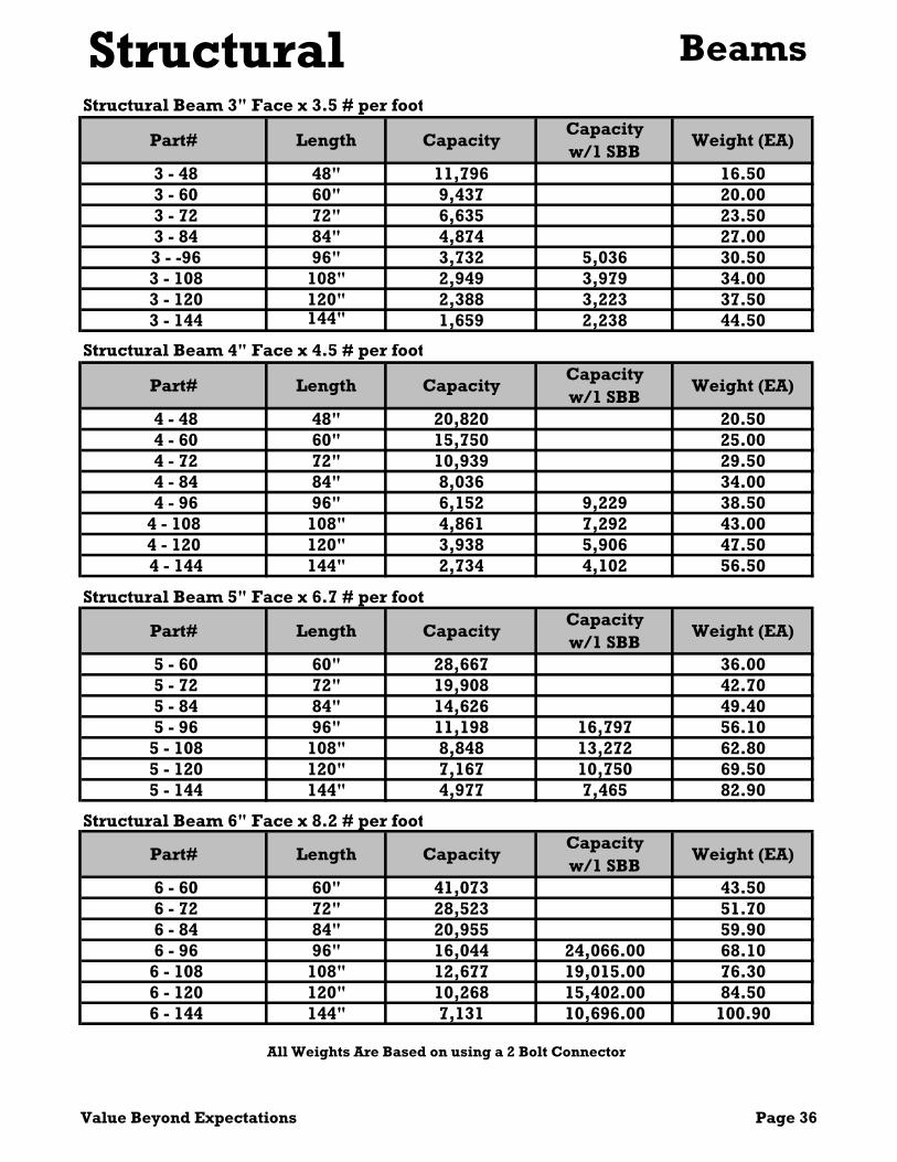
StructuralPart# Length Capacity
Capacity w/1 SBB
Weight (EA)
3 - 48 48" 11,796 16.50 3 - 60 60" 9,437 20.00 3 - 72 72" 6,635 23.50 3 - 84 84" 4,874 27.00 3 - -96 96" 3,732 5,036 30.50 3 - 108 108" 2,949 3,979 34.00 3 - 120 120" 2,388 3,223 37.50 3 - 144 144" 1,659 2,238 44.50
Structural Beam 4" Face x 4.5 # per foot
Part# Length CapacityCapacity w/1 SBB
Weight (EA)
4 - 48 48" 20,820 20.50 4 - 60 60" 15,750 25.00 4 - 72 72" 10,939 29.50 4 - 84 84" 8,036 34.00 4 - 96 96" 6,152 9,229 38.504 - 108 108" 4,861 7,292 43.004 - 120 120" 3,938 5,906 47.50 4 - 144 144" 2,734 4,102 56.50
Part# Length CapacityCapacity w/1 SBB
Weight (EA)
5 - 60 60" 28,667 36.00 5 - 72 72" 19,908 42.70 5 - 84 84" 14,626 49.40 5 - 96 96" 11,198 16,797 56.10
5 - 108 108" 8,848 13,272 62.80 5 - 120 120" 7,167 10,750 69.50 5 - 144 144" 4,977 7,465 82.90
Part# Length CapacityCapacity w/1 SBB
Weight (EA)
6 - 60 60" 41,073 43.50 6 - 72 72" 28,523 51.70 6 - 84 84" 20,955 59.90 6 - 96 96" 16,044 24,066.00 68.10
6 - 108 108" 12,677 19,015.00 76.30 6 - 120 120" 10,268 15,402.00 84.50 6 - 144 144" 7,131 10,696.00 100.90
Beams
Structural Beam 6" Face x 8.2 # per foot
Structural Beam 3" Face x 3.5 # per foot
Structural Beam 5" Face x 6.7 # per foot
All Weights Are Based on using a 2 Bolt Connector
Value Beyond Expectations Page 36

StructuralStructural Safety Support Overlap Style
Part# Length Weight (EA)SSS-36 36" 10.80SSS-42 42" 12.50SSS-44 44" 13.10SSS-48 48" 14.30
Part# Length Weight ea.SBB-36 36" 6.00
SBB-42 42" 6.80
SBB-44 44" 7.00
SBB-48 48" 7.70
SBB-54 54" 8.50
Structural Bolted Safety Support With Roll-Formed Body
Part# Length Weight ea.RFSBB-36 36" 4.40
RFSBB-42 42" 5.10
RFSBB-44 44" 5.40
RFSBB-48 48" 5.80
RFSBB-54 54" 6.60
Structural Bolted Safety Support
Beam Accessories
Page 37 Value Beyond Expectations

Cantilever Rack
Cantilever Racks are ideal for storage of long, bulky products such as carpet rolls, lumber, pipe, tubing and other similar products.
Hannibal cantilever racks are available in a heavy-duty structural or medium duty roll-formed design.
Features: Strong, Safe and Economical Wide Variety of Options Available High Quality Powder Coat Finish


Value Beyond Expectations Page 40
ARM LENGTH
CA357ARM
WEIGHT CA477
ARM WEIGHT
CA510ARM
WEIGHT CA609
ARM WEIGHT
24" 4,100 16.70 7,500 20.60 12,000 25.10 13,800 23.2036" 2,400 22.40 4,500 28.30 7,800 35.10 9,100 32.2048" 1,350 28.10 3,000 36.10 5,200 45.10 6,800 41.2060" 850 33.80 1,900 43.70 3,500 55.10 5,000 50.20
Horitzontal Bay C/C WEIGHT WEIGHT CAHB-36 36" 9.20 10.70CAHB-48 48" 12.30 11.60CAHB-60 60" 15.20 12.70CAHB-72 72" 18.40 14.00CAHB-96 96" 24.40 16.80
CAHB-120 120" 30.60 26.10
Hannibal recommends that all cantilever projects be reviewed by a structural engineer before quoting.
Static Arm Capacity Chart
X-Bracing 2" x 109A FlatNote: All Capacities Listed are Static Only
CAXB-12060
Bracing Tables
Cantilever Arms & Bracing
*** NOTE HANNIBAL STANDARD PANEL HEIGHT IS 60" Horizontal - 2" x 2" x 3/16"
X-BRACE SET CAXB-3660CAXB-4860CAXB-6060CAXB-7260CAXB-9660

Page 41 Value Beyond Expectations
Part Number HEIGHTBracing panels
WEIGHT 24" 36" 42" 48" 60"
CAUS-818 96 1 156.12 21,000 17,000 15,000 13,500 11,500CAUS-818 120 1 192.12 21,000 17,000 15,000 13,500 11,500CAUS-818 132 1 210.12 21,000 17,000 15,000 13,500 11,500CAUS-818 144 2 228.88 15,500 12,500 11,500 10,500 9,500CAUS-818 168 2 264.82 15,500 12,500 11,500 10,500 9,500CAUS-818 192 2 300.82 15,500 12,500 11,500 10,500 9,500CAUS-818 216 3 337.52 15,500 12,500 11,500 10,500 9,500CAUS-818 240 3 373.52 15,500 12,500 11,500 10,500 9,500CAUS-818 252 3 391.52 15,500 12,500 11,500 10,500 9,500CAUS-818 264 4 410.59 12,000 10,000 9,000 8,500 7,500CAUS-818 288 4 446.59 12,000 10,000 9,000 8,500 7,500CAUS-818 336 5 518.92 12,000 10,000 9,000 8,500 7,500
Part Number HEIGHT Bracing panels WEIGHT 24" 36" 42" 48" 60"
CAUS-821 96 1 180.43 25,000 20,500 18,000 16,500 13,500CAUS-821 120 1 222.43 25,000 20,500 18,000 16,500 13,500CAUS-821 132 1 243.43 25,000 20,500 18,000 16,500 13,500CAUS-821 144 2 265.15 19,000 15,500 14,000 13,000 12,000CAUS-821 168 2 307.15 19,000 15,500 14,000 13,000 12,000CAUS-821 192 2 349.15 19,000 15,500 14,000 13,000 12,000CAUS-821 216 3 391.87 19,000 15,500 14,000 13,000 12,000CAUS-821 240 3 433.87 19,000 15,500 14,000 13,000 12,000CAUS-821 252 3 454.87 19,000 15,500 14,000 13,000 12,000CAUS-821 264 4 476.59 14,500 12,000 11,000 10,500 9,000CAUS-821 288 4 518.59 14,500 12,000 11,000 10,500 9,000CAUS-821 336 5 603.31 14,500 12,000 11,000 10,500 9,000
Part Number HEIGHT Bracing panels WEIGHT 24" 36" 42" 48" 60"
CAUS-1022 96 1 192.29 30,500 24,000 22,000 20,000 17,000CAUS-1022 120 1 236.29 30,500 24,000 22,000 20,000 17,000CAUS-1022 132 1 258.29 30,500 24,000 22,000 20,000 17,000CAUS-1022 144 2 280.43 25,000 20,000 18,500 17,000 16,000CAUS-1022 168 2 324.43 25,000 20,000 18,500 17,000 16,000CAUS-1022 192 2 368.43 25,000 20,000 18,500 17,000 16,000CAUS-1022 216 3 413.17 25,000 20,000 18,500 17,000 16,000CAUS-1022 240 3 457.17 25,000 20,000 18,500 17,000 16,000CAUS-1022 252 3 479.17 25,000 20,000 18,500 17,000 16,000CAUS-1022 264 4 501.89 20,000 17,000 15,500 14,500 12,500CAUS-1022 288 4 545.89 20,000 17,000 15,500 14,500 12,500CAUS-1022 336 5 634.61 20,000 17,000 15,500 14,500 12,500
Static Capacity per Side
Cantilever ColumnsStatic Capacity per Side
Static Capacity per Side

Value Beyond Expectations Pg 42
Part Number HEIGHTBracing panels
WEIGHT 24" 36" 42" 48" 60"
CAUS-1026 96 1 223.73 36,500 28,500 26,500 24,000 20,500CAUS-1026 120 1 275.73 36,500 28,500 26,500 24,000 20,500CAUS-1026 132 1 301.73 36,500 28,500 26,500 24,000 20,500CAUS-1026 144 2 328.43 30,000 24,500 22,000 20,500 19,500CAUS-1026 168 2 380.43 30,000 24,500 22,000 20,500 19,500CAUS-1026 192 2 432.43 30,000 24,500 22,000 20,500 19,500CAUS-1026 216 3 485.17 30,000 24,500 22,000 20,500 19,500CAUS-1026 240 3 537.17 30,000 24,500 22,000 20,500 19,500CAUS-1026 252 3 563.17 30,000 24,500 22,000 20,500 19,500CAUS-1026 264 4 589.89 24,500 20,500 19,000 17,500 15,500CAUS-1026 288 4 641.89 24,500 20,500 19,000 17,500 15,500CAUS-1026 336 5 746.61 24,500 20,500 19,000 17,500 15,500
Part Number HEIGHT Bracing panels WEIGHT 24" 36" 42" 48" 60"
CAUS-1422 96 1 193.25 21,500 25,500 23,000 21,000 18,000CAUS-1422 120 1 237.25 21,500 25,500 23,000 21,000 18,000CAUS-1422 132 1 259.25 21,500 25,500 23,000 21,000 18,000CAUS-1422 144 2 281.95 28,000 23,000 21,000 20,500 17,500CAUS-1422 168 2 325.95 28,000 23,000 21,000 20,500 17,500CAUS-1422 192 2 369.95 28,000 23,000 21,000 20,500 17,500CAUS-1422 216 3 414.98 28,000 23,000 21,000 20,500 17,500CAUS-1422 240 3 458.98 28,000 23,000 21,000 20,500 17,500CAUS-1422 252 3 480.98 28,000 23,000 21,000 20,500 17,500CAUS-1422 264 4 503.7 24,500 20,500 19,000 17,500 15,500CAUS-1422 288 4 547.7 24,500 20,500 19,000 17,500 15,500CAUS-1422 336 5 636.42 24,500 20,500 19,000 17,500 15,500
Part Number HEIGHT Bracing panels WEIGHT 24" 36" 42" 48" 60"
CAUS-1626 96 1 230.64 39,500 31,500 29,500 27,000 23,000CAUS-1626 120 1 282.64 39,500 31,500 29,500 27,000 23,000CAUS-1626 132 1 308.64 39,500 31,500 29,500 27,000 23,000CAUS-1626 144 1 334.64 36,000 29,000 27,000 26,000 22,500CAUS-1626 168 2 387.34 36,000 29,000 27,000 26,000 22,500CAUS-1626 192 2 439.34 36,000 29,000 27,000 26,000 22,500CAUS-1626 216 3 492.08 36,000 29,000 27,000 26,000 22,500CAUS-1626 240 3 544.08 36,000 29,000 27,000 26,000 22,500CAUS-1626 252 3 570.08 36,000 29,000 27,000 26,000 22,500CAUS-1626 264 4 596.8 32,500 27,000 24,500 23,000 22,000CAUS-1626 288 4 648.8 32,500 27,000 24,500 23,000 22,000CAUS-1626 336 5 753.52 32,500 27,000 24,500 23,000 22,000
ColumnsCantilever Static Capacity per Side
Static Capacity per Side
Static Capacity per Side

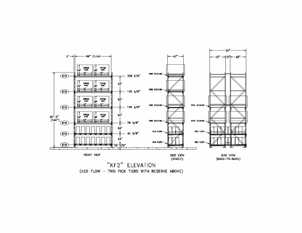
The Hannibal Keg Storage System provides beer wholesalers a better way to store barrel kegs. The system provides picking location by barrel stored on heavy duty steel rollers with reserve on top
Features and Benefits: Heavy duty Keg-Flo will consolidate your items and provide better ergonomics for picking.
Increase SKU pick locations by 30% while reducing the space required by as much as 50%.

KEG-FLO Data Sheet
Customer Name:
Address:
State:
Contact: Phone:
Cell:
Email: Expected order date: Expected Installation date: Existing beams or new: If existing, specify vertical adjustability:
1) Provide beam dimensions. Specify beam height and if load beams are roll formed or structural.
2) Keg-Flo lane sizes available (circle size needed):
1. Sixth barrel keg (7 lanes wide per level @ 8’ wide bay)
2. Quarter barrel keg (4 lanes wide per level @ 8’ wide bay)
3. Slim quarter barrel keg (5 lanes wide per level @ 8’ wide bay) (11.5” diameter keg)
4. Half barrel keg (4 lanes wide per level @ 8’ wide bay)
3) Typical number of kegs deep
1. Sixth barrel keg (4 kegs deep per level @ 42” deep frame)
2. Quarter barrel keg (2 kegs deep per level @ 42” deep frame)
3. Slim quarter barrel keg (3 kegs deep per level @ 42” deep frame) (11.5” diameter keg)
4. Half barrel keg (2 kegs deep per level @ 42” deep frame)
Note: Quantity of kegs deep varies depending on which types of load beams used and frame depth. Roll formed step beams typically allow one less keg deep. 4) Specify how many levels/bays


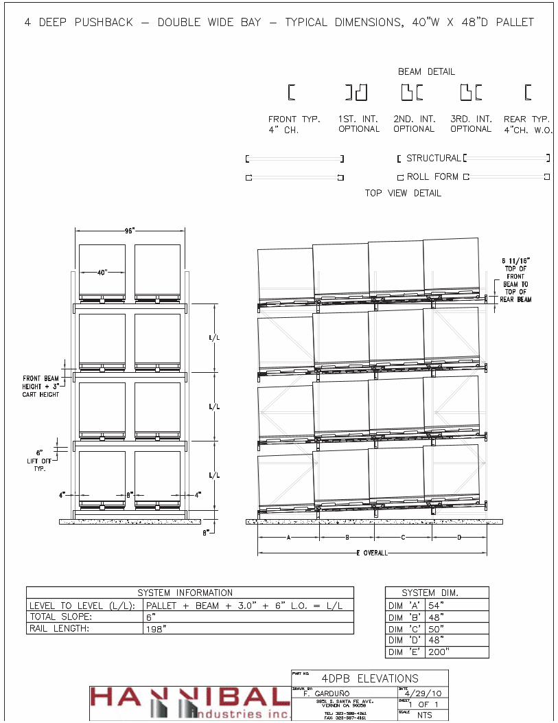
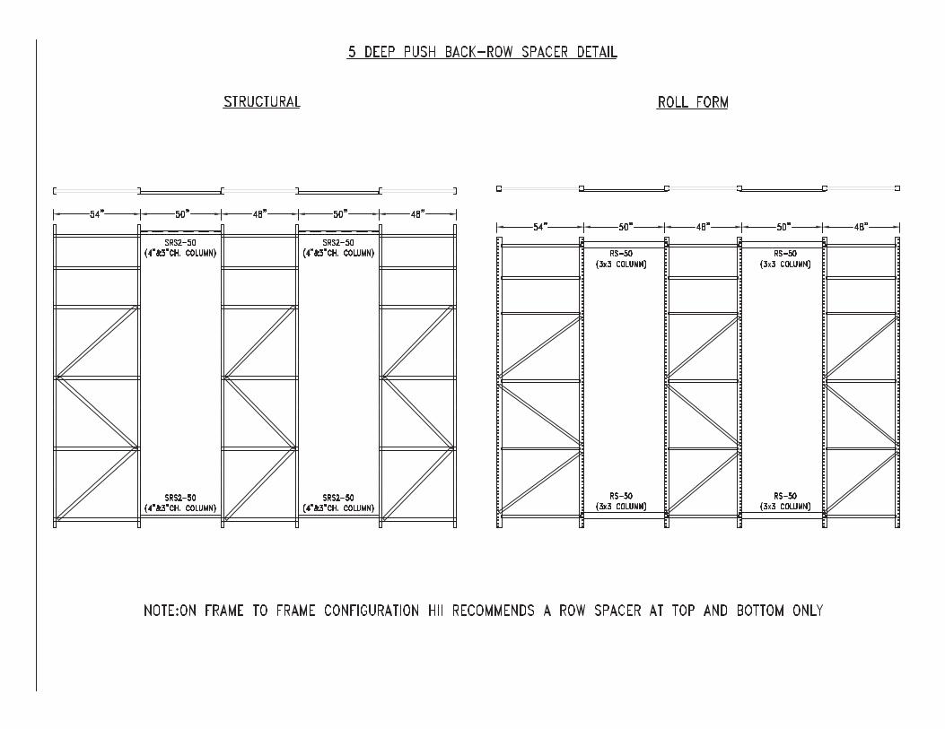
Hannibal Pushback Systems are manufactured using heavy duty structural tube support rails combined with steel wheels.
Features: Up to 3,000 lbs. Capacity 2-6 Deep Systems Maximizes Storage Capacity High Quality Powder Coat Finish Flanged Steel Wheels Strongest Wheels in the Industry
Benefits: Carts are linked when extended which eliminates the possibility of single pallet hang-ups.
Each cart is equipped with lift out protectors to prevent accidental dislodgement of carts.
The structural steel tube rail design provides long term durability and ease of installation.
Our engineering and OEM partners can help design your specialty application.

Request for Pushback

Low Profile Design
Carts are linked when extendedwhich eliminates the possibility of single pallet hang-ups at rear of lane.
Each cart is equipped with lift out protectors to prevent accidental dislodgement of carts.
The structural steel tube rail design provides long term durability and ease of installation.
Our engineering and OEM partners can help design your specialty applica-tion.
Benefits of Pushback Systems
(866) 513-1200 | hannibalrack.com

LOW PROFILESteadiflo has a lower profile than other
cart type systems. This allows for extra lift
clearance and may even mean the
difference of an extra level.
SIMPLE DESIGN AND EASE OF INSTALLATIONThe Steadiflo design allows for easy
installation, with wheels preinstalled
from the factory and simple drop-in rail
design that requires rack attachment
at the front and rear only.
3D Storage Systems uses a unique design that provides trouble free operation as
well as extensive built-in safety features. Structural steel construction
ensures long life in tough warehouse environments.
LIFT-OUT PROTECTORSEach cart is equipped with lift-out
protectors, which prevent accidental
dislodgement of a cart by the
forklift operator.
77
STEADIFLO PUSHBACK – FEATURES AND BENEFITS.

PUSH PLATE AND SAFETY STOPHeight Gauge – When loading a pallet, the
operator knows that if a load is high enough
to clear the safety stop, then the pallet will
not prematurely move the awaiting cart.
Strip-Off Stop – If, after placing a pallet, the
operator has his forks in an improper tilt
position, the safety stop will catch the bottom
of the pallet and “strip" it off his forks.
End Stop – The safety stop, which is situated
on the lowest cart and protrudes 3/4" above the highest cart, prevents pallets from
shifting beyond the front load beam.
Push Plate – Pushing on the plate with the last pallet being inserted into the lane
ensures proper placement on the rails as well as guaranteeing safe clearance of
the cart.
Lane Full Indicator – The operator can tell if a lane is full by the absence of the safety
stop. If it is not showing at the front, the last cart has been loaded and there is a
pallet on the rails – a full lane.
LINKED CARTSCarts are linked when extended, eliminating
the possibility of single pallet hang-ups.
Without this feature, it would be possible
for a pallet to become temporarily lodged
at the back of a lane, release, and travel in
an uncontrolled manner to the load end,
spilling the load. The resultant potential for
damage to product, and more importantly,
personal injury, is obvious. No pushback
product is complete without this important
safety feature.
FLANGED STEEL WHEELS
Our wheels are manufactured from solid
steel and are equipped with heavy duty
bearings. Sturdy 5/8" shafts are welded to
the carts and are oversized to withstand
shock loading, capacities of up to 1,400 lbs.
per wheel.
88

PUSHBACK – QUESTIONS AND ANSWERS
How much slope do the rails have?The system utilizes a slope of 3/8" per foot, or just a little less than two degrees. For
example, a standard 4 deep lane for 48" deep pallets would have 6" of slope. This
slope ensures that empty carts will always return to the front of the lane if
accidentally pushed back by the operator. In most cases the total slope is less than
the lift clearance above the pallet at the load end, and therefore, does not affect the
number of storage levels.
Do I need special forklifts?No. There are systems installed with counterbalance, reach, deep-reach,
swing-reach and even clamp trucks.
What size of aisle do I require?Aisles should be of sufficient width to allow an operator to square-up to the
pallet without turning into the rack. Usually this is 6" more than the truck
manufacturers’ minimum aisle requirement.
-How much push force is required by the forklift?Approximately 4% of the total weight being pushed back, not counting the pallet
on the forks of the truck (i.e. 2,000 lbs. on a 6-deep would require 400 lbs. of push
force to load). This is well within the capabilities of most lift trucks. We have several
installations of six deep in freezers with reach trucks.
What are the space requirements?The following are general rules of thumb
• Vertical level to level of beamsFor 2, 3 and 4 deep pushback – pallet height + 12"For 5 and 6 deep pushback – pallet height + 14"
• Rack depth (# of pallets deep X (pallet depth + 2")) + 2" (i.e. 102", 152", 202", 252" and 302" for a 48" deep pallet for 2 /3 /4/5/6deep)
• Beam WidthSingle wide bays - pallet + 8" Double wide bays - (pallet x 2) + 16"
What about temperature restrictions?We have installations that range in temperature from +50 to -30 degrees Celsius,
including blast freezers.
99

How difficult is it to load and unload?Experience has shown that most operators are completely efficient within a half
day. Many operators state that pushback is easier to load and unload than standard
pallet rack. Operating instructions are sent with each system.
What about maintenance?There is no required maintenance. Bearings are permanently lubricated.
Can you achieve FIFO with Pushback?Contrary to popular belief, it is easy to achieve first-in, first-out with pushback
racking. The key is to configure your system to ensure that each product (SKU)
utilizes multiple lanes. If each product has three or four lanes of pushback, the
operator simply ships out the oldest lane first.
How does 3D pushback compare to the competition?
• 3D has one of the lowest profiles in the market. Our 5 and 6 deep lanes are half
the height of most other systems. This height difference results in extra lift
clearance and future load height flexibility – it may also allow an extra pallet level.
• Our pushback system is equipped with several key safety features that others
do not offer – linked carts, lane full indicators, pallet stops and cart lift-out
protectors are all standard features.
• 3D assembles the carts before we ship them, including attaching shafts and
wheels to the carts at our facility. We also only mount to the front and rear
beams and do not need to mount to the internal beams. This results in faster
and less expensive installations.
• We have some of the strongest wheels and shafts in the industry – the wheels
are rated at 1,400 lbs and the 5/8” solid steel shafts are welded to the cart.
• We offer 2 to 6 deep pushback to best suit the layout and application. Many
others manufacture only 2 and/or 3 deep lanes. We also can produce many
non-standard designs depending on the application, such as steel sheet or
mesh covered carts, heavy duty lanes and level carts.
1100

PUSHBACK ELEVATION CALCULATOR
By following this simple 4 step process to calculate the level to level, beam heights,
clear height required and lift height required, you will know whether a
system will fit into the area you have available. If you have any questions or
special considerations please do not hesitate to contact 3D Storage Systems for
assistance with any of these calculations.
Based on standard design 40"F x 48"D GMA/CHEP pallet 3,000 lbs. max.
Step A – Level to Level – (Top of beam to top of beam)
Example: 48" load height – 4-Deep
*Always round-up to the next module, if calculation does not divide evenly into the
”module“ or adjustability of the rack system.
**1" of space is sufficient when the front frame of the racking system is 6" deeper
than the depth of the pallet (i.e. 54" front frame with a 48" pallet depth).
Step B – Calculating Beam LevelsExample: 4-Deep Pushback, 4 levels high, 48" load height
Based on the calculation in ‘Step A’ we know 48" load height will equal 60" L/L
with a 4-deep pushback. Generally the top of the first level beam will be at 8" unless
you are floor mounting in which case it would be 3". Therefore at 4 levels high we
would have beam levels at 8", 68", 128" and 188".
Sample Insert
Load Height 48"
+ Equipment Height +6"
+ Internal Beam Size +5"
+ Space (1" is sufficient**) +1" +1"
= level to level *= 60" L/L = L/L
1111
Depth of Pushback Equipment Height Slope of System
2-Deep 4.8125" 3"
3-Deep 5.375" 4.5"
4-Deep 6" 6"
5-Deep 6.75" 7.5"
6-Deep 7.625" 9"

Step C – Calculating Clear Height RequiredExample: 4-Deep Pushback, 4 levels high, 48" load height
Based on the calculation in ‘Step B’ we know where the top beam level would
be, which in our sample calculation is 188".
Step D – Calculating Lift Height RequiredExample: 4-Deep Pushback, 4 levels high, 48" load height
Based on calculation ‘B’ we know our top beam level would be 188".
Sample Insert
Top of top beam 188"
- Top of beam to bottom of rail -2.75" (standard) -2.75"
+ Equipment Height +6"
+ Lift +8" +8"
= Lift Height =199.25" =
1122
Sample Insert
Top of top beam 188"
- Top of beam to bottom of rail -2.75" (standard) -2.75"
+ Load Height +48"
+ Equipment Height +6"
+ Slope +6"
+ Space (2" is sufficient) +2" +2"
= Clear Height Required =247.25" =


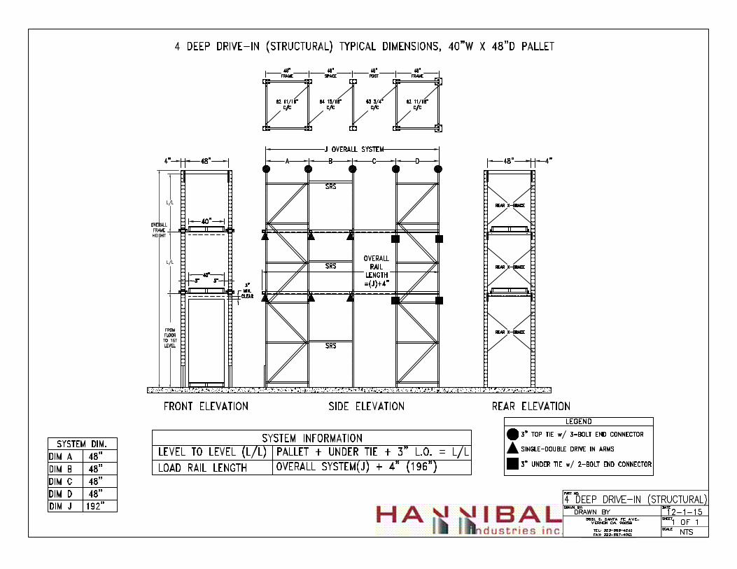
Drive-In Systems
Doublewide Drive-In offers a unique racking system designed for maximum space utilization and productivity.
Industries Served Beverage Agricultural (Fruits & Vegetables) Import and Export Facilities 3rd Party Logistic Centers Grocery Dairy Food Services Food Manufacturing Bulk Product Handling Petroleum, Chemical and Paint


Hannibal Industries, Inc. Los Angeles, CA (866) 513-1200 (323) 588-4261 (323) 587-4061 fax www.hannibalindustries.com
Pallet Rack Mix & Match Drive-In Push-Back Pallet Flow Carton Flow Stacking Steel Pallets Wire Deck
Introduction to Pallet Rack
Value Beyond Expectations
Hannibal Industries, Inc.
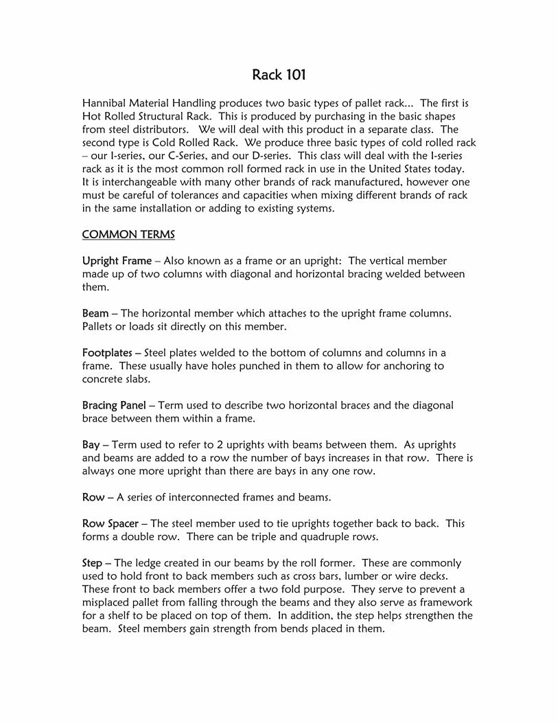
Rack 101 Hannibal Material Handling produces two basic types of pallet rack... The first is Hot Rolled Structural Rack. This is produced by purchasing in the basic shapes from steel distributors. We will deal with this product in a separate class. The second type is Cold Rolled Rack. We produce three basic types of cold rolled rack – our I-series, our C-Series, and our D-series. This class will deal with the I-series rack as it is the most common roll formed rack in use in the United States today. It is interchangeable with many other brands of rack manufactured, however one must be careful of tolerances and capacities when mixing different brands of rack in the same installation or adding to existing systems. COMMON TERMS Upright Frame – Also known as a frame or an upright: The vertical member made up of two columns with diagonal and horizontal bracing welded between them. Beam – The horizontal member which attaches to the upright frame columns. Pallets or loads sit directly on this member. Footplates – Steel plates welded to the bottom of columns and columns in a frame. These usually have holes punched in them to allow for anchoring to concrete slabs. Bracing Panel – Term used to describe two horizontal braces and the diagonal brace between them within a frame. Bay – Term used to refer to 2 uprights with beams between them. As uprights and beams are added to a row the number of bays increases in that row. There is always one more upright than there are bays in any one row. Row – A series of interconnected frames and beams. Row Spacer – The steel member used to tie uprights together back to back. This forms a double row. There can be triple and quadruple rows. Step – The ledge created in our beams by the roll former. These are commonly used to hold front to back members such as cross bars, lumber or wire decks. These front to back members offer a two fold purpose. They serve to prevent a misplaced pallet from falling through the beams and they also serve as framework for a shelf to be placed on top of them. In addition, the step helps strengthen the beam. Steel members gain strength from bends placed in them.

Roll formed I – Series Rack Cold Rolled I series rack starts out as a “mother” coil – flat thin steel rolled into a coil. This is usually 49” to 50” wide and weighs 49,000# to 50,000#. This coil goes into our slitter and is cut into smaller coils of varying widths as demanded by the blank sizes of our various products. These same smaller coils of steel are put onto the feed end of our roll formers where they are fed through our machines at ambient temperatures that bend them and punch them to the desired shapes. There are different roll formers for columns, column bracing, and beams. The cut-off machine at the end of the roll former line cuts each shape to a predetermined length. The end result is both a column (which is paired with another column and bracing which is welded between these to form a frame) or a beam. The column or frame usually has footplates welded to the bottom for anchoring to a concrete slab. The beam usually has C5 or C6 end plates welded to each end. The end plates have rivets with pins in them – 3 for a C5 and 4 for a C6. These end plates are produced outside of our facility and are brought in as needed. The brackets/rivets of the beam fit into the front punching of the upright frame much as an erector set. In addition, each bracket has a spring loaded locking mechanism which locks it into place once it is attached to the column of the frame. The columns of each frame have punchings on the fronts and sides. Both punching sets are on 2” centers and allow for beam adjustability on 2” centers along the length of the column. See below

Components which make up an upright frame: Roll Formed Columns, Footplates, Roll formed horizontal bracing and roll formed diagonal bracing. See drawing.
Side View of Upright Frame

Proper Sizing and Selection of Frames and Beams: Determining Depth of Frame The depth of a frame is determined by the size of the pallet a customer plans to store on it. At this point one can forget about the load on top the pallet and concentrate only on the pallet itself. The most common pallet available is what is known as a GMA pallet. This stands for Grocery Manufacturers Association. When talking about pallet size the depth (front to back) of a pallet is always the first number given and the width (left to right) is the second number given. For instance, a GMA pallet is 48” x 40” – that is; 48” deep x 40” wide. When determining the proper depth of the frame to be used one must take the pallet depth – which in this case is 48” and deduct 2” to 3" from the front and 2” to 3” from the rear. The ideal situation for storing pallets on rack is for the pallet to overhang the rack 2” to 3” both front and rear. Therefore the frame best suited to a 48” deep pallet is either 44” or 42” deep. Since 42” deep is the more common size that is probably the best selection. The reason behind this is that when a forklift operator is putting away a pallet in upper levels it is wise to allow overhang so that the driver doesn’t inadvertently miss the beam when setting the pallet down (which could cause the pallet to fall through the beams.) See drawing:

Determining Height of Frame – See drawing The height of the frame is determined by quite a few factors. These are:
1. Height of building to underside of sprinklers heads. 2. Type of sprinkler system in the building.
(Note: These two variables are part of the fire code which states that the top of the load on your pallet must be a certain distance from the underside of the sprinkler heads. This can vary anywhere from 18” to 36”).
3. The lift height of the forklift to be used. 4. Most importantly – the height of the load including the pallet.
In sizing the height of an upright frame one must know the height of the load plus the pallet. Five to six inches should be added to this for the pallet to be lifted into and out of the rack. The height of the beam must also be taken into consideration. If we looked at the front view of a pallet rack bay which is properly designed it might look something like this: (See drawing)
Since the more common size upright is in even one foot increments one would probably recommend a 20’ high or 240” high frame.

Now that we have properly selected the height and depth of our uprights you should be aware that you must also choose a model or part number. The model number is a combination of the actual size of the column the frame is made of and its gauge. The gauge is the thickness of the steel which formed the columns. Hannibal offers the following selection: Two sizes of columns (3” x 3” OR 3” x 1-5/8”) and four gauges (14, 13, 12, and 11). In addition, column backers can be welded to front and/or rear columns in these same combinations to produce an even heavier frame with more capacity. Our model numbers indicate the above available choices as follows: Model Number IF1514-42144 I – “I” Series F – Frame 15 – Size of columns (3” x 1-5/8”) 14 – Gauge of steel 42 – Depth of frame 144 – Height of frame The above model number indicates an I-Series roll formed frame with columns that are; 1 5/8” deep x 3” wide and 14 gauge. Model Number IF3013-42240 I – “I” Series F – Frame 30 – Size of Columns (3” x 3”) 13 – Gauge of steel 42 – Depth of Frame 240 – Height of Frame When dealing with gauges, the smaller the number the thicker the steel. Therefore a 13 gauge frame would be thicker and heavier than a 14 gauge frame. Hannibal offers frames with: 3” x 1 5/8” columns in 14 gauge or 3” x 3” columns in gauges as follows: 14, 13, 12 and 11.

Who determines how much capacity is needed in a frame and what is capacity? Capacity is the amount of weight which can safely be placed on a frame in a given situation. You will notice that our price book contains a frame capacity chart. These are the capacities each frame can hold in a perfect condition – namely in a seismic zone “0” area. The loading values stated in almost all manufacturers literature is for vertical loading only – that is the amount of weight uprights will hold in a static (non-moving) situation. Seismic zones indicate the likelihood of the earth moving (earthquake). The higher the seismic zone the likelihood of an earthquake to occur and the more severe the earthquake could be. In southern California we are in the most severe seismic zone – zone 4. Capacities of rack uprights drop dramatically in zone 4. An upright which will hold 35,000 pounds in a static (non-moving) situation may hold only 15,000 pounds during a seismic event. We will go into this area further on future training sessions. For now, you should urge your customer to obtain preliminary seismic calculations from a certified, licensed engineer in order to make an upright frame selection. Other items which are commonly effected by seismic zones are footplates (size of footplate, distance between holes for anchoring, size of holes for anchoring, thickness of footplate), beams (some may require extra capacity as lower levels sometimes receive extra loading from loads transmitted down through the column), beam end plates (brackets) including size of endplates and number of pins required – in short – virtually every component of a racking system can be effected by placing the assembled bay into a seismic zone area. All of these items will be discussed more in depth in future training sessions.

Sizing and Selection of Beams: Beams are sized on the basis of the loads to be placed on them. The first piece of information you must know is the width of the load be placed on the beams. Next you must find out how many loads wide will be stored in one bay. This is normally only two unless one is dealing with a tunnel bay or extremely light loads. Loading of pallet rack is also limited by the capacity of a customer’s concrete slab, i.e., this is the reason most customers only store two pallets wide per pair of beams. To determine the correct length of beam to be used one must take the width of the load to be used times the number of pallets wide (we will use two in this example) plus 3” to 4” between each load (if a standard forklift is to be used in the application) and the upright column and another 3” to 4” between pallets - . Thus, if a customer has a 42” wide load and is storing two pallets wide and is using a standard forklift the proper beam size would be around 96”. (See drawing)

If a customer is using a turret style truck or Drexel truck it is advisable to increase the distance between load and upright columns and between pallets to 5” to 6”. In this case a 102” beam would be advisable. If a customer has varying load widths always size for the largest loads. The model number of the beam to be used is determined by how much capacity is required. Beams should be selected based on the HEAVIEST loads to be stored on them. Our price book shows capacities which are based on a PAIR of beams. Beam capacities are most affected by the height of the beam, the gauge of the beam, and the length of the beam. The longer the beam, the less capacity it will have. Capacities are normally calculated based on beam deflection – that is – how much a beam will bend under loading conditions. Allowable deflection for beams in a pallet rack system is calculated using the formula L/180 – that is – the length of the beam divided by 180”. This will give you a result in fractions of an inch which is the allowable deflection for this length beam. For instance, a 96” beam is allowed to have .533” of deflection – a little more than a half inch. Let us assume that we have two loads which will weigh a maximum of 2,388 pounds each – our load requirement for the pair of beams they will rest on is 4,776 pounds. We will also assume that we have already determined that we require a 96” beam for these loads. Looking in our price book you will notice that our I33140-96 will hold 4,055 pounds per pair. This is not quite enough. Our next size up is the I36140-96 which will hold 5,254 pounds per pair – this would be the proper selection for this loading condition. It is perfectly ok to use a beam with more capacity than is necessary. IT IS NEVER OK to use a beam which has less capacity than may be necessary. When in doubt always go to the beam with more capacity. Beam model numbers also indicate their properties: For example: I30140-96-C5 I = I Series rack 30 = 3” high beam 14 = 14 gage 96 = 96” long C5 = 3 pin bracket (also known as the end plate)
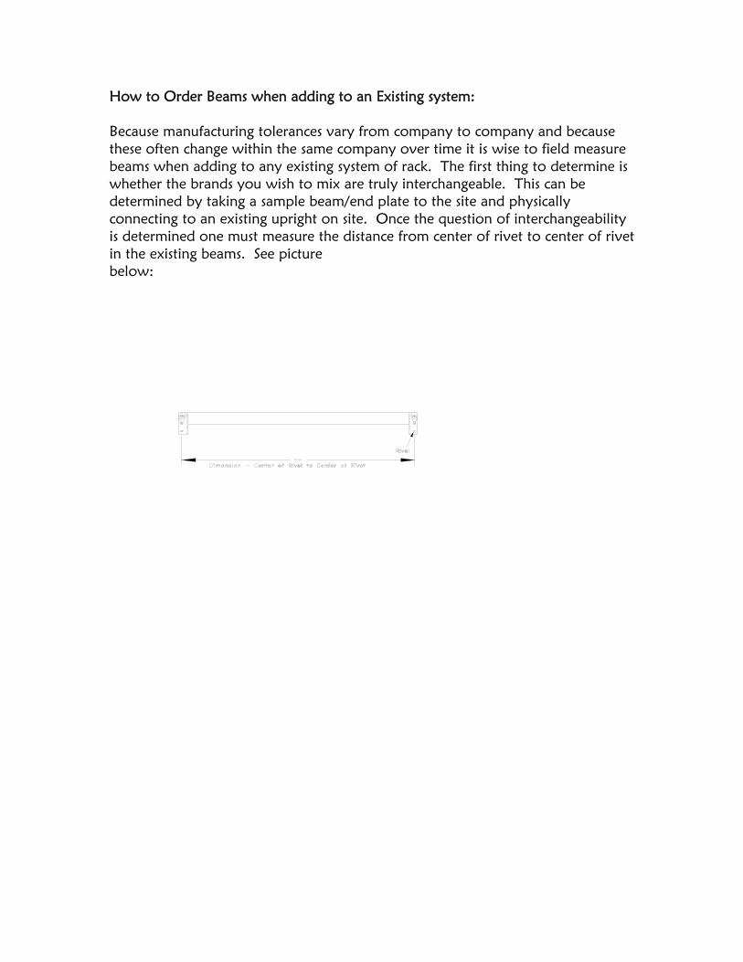
How to Order Beams when adding to an Existing system: Because manufacturing tolerances vary from company to company and because these often change within the same company over time it is wise to field measure beams when adding to any existing system of rack. The first thing to determine is whether the brands you wish to mix are truly interchangeable. This can be determined by taking a sample beam/end plate to the site and physically connecting to an existing upright on site. Once the question of interchangeability is determined one must measure the distance from center of rivet to center of rivet in the existing beams. See picture below:

Wire Decking 101:
CHOOSING THE CORRECT CHANNEL FOR YOUR BEAM When deciding what type of wire deck to use for a project, it is important to consider what type of support channel is correct for your application. Since most of the deck capacity comes from the support channels, it is necessary to have the correct channel in order for the deck to perform properly. Several factors determine which channel is best for each application. One factor is the style and branch of racking that the deck will be sitting on. If structural or box beams are being used, then a Flanged or Flared Style Channel is required. Not just any Flange channel will function properly. For optional strength, the flanged part of the channel should be no more than ¼” wider than beam itself. For instance, if the box beam is 1-3/4” wide then the flange should be no longer than 2”. If the deck is going to be sitting on step beams, then a Step or Standard style channel is the best choice for maximum capacity. There are many variables to a step beam that affect which standard channel is best for each application. The channel should fit inside the step with no more than ¼” of play between the step ledges. For example, if a 42” deep rack has an inside step dimension of 38-1/2” the proper fitting channel is 38-1/4”. In addition, the channel should be resting on the step ledge with the wire mesh slightly above or resting on the top of the beam. Using Flanged Style channels with a step beam is not recommended! Another factor to consider when choosing the right channel is the load. In most food applications, the channel with the legs pointed upward may not be acceptable for the reason that food may get caught in the channels. The alternative is to invert the channel and weld it to the deck so that the legs point down. This type of channel is an Inverted channel. The major drawback to an Inverted channel is loss in capacity. Capacity is also a factor when considering the channel type. A high capacity load may require multiple channels or a channel made out of material that is of a higher gauge. For the proper storage of product and the safety of others, it is important to address all information regarding the use of the correct channels for your decking application. Please remember, one size does not fit all!

Engineer Directory
Seizmic Engineering Sal Fateen, Owner Mike Obe, Engineer 161 Atlantic Street Pomona, CA 91768 (909) 869‐0989
(909) 869‐0981 Fax [email protected]
Andrew Kirby 29653 Quail Run Drive Agoura Hills, CA 91301
(818) 735‐0719 (818) 735‐0355 Fax [email protected]
Rack Design & Engineering Gary Ohan, Owner
412 West Broadway Ste. 204 Glendale, CA 91240 (818) 240‐3810
(818) 240‐3813 Fax [email protected]
Structural Concepts Engineering Al Hassani
Bobby Sharifi 1200 S. Jefferson St. Ste. F
Anaheim, CA 92807 (714) 632‐7330
(714) 632‐7763 Fax [email protected]
Peter Higgins 30765 Pacific Coast Hwy #117
Malibu, CA 90265 (310) 589‐1781
(310) 589‐5194 Fax [email protected]
Curry‐Riehl & Associates Engineering Ben Riehl
1668 Glen Eagles Blvd. Billings, MT 59105 (406) 256‐3699
(406) 259‐2901 Fax [email protected]

Requested By:Requested By:Requested By:Requested By: Project Name:Project Name:Project Name:Project Name:
Company: Company: Company: Company: Project Address:Project Address:Project Address:Project Address:
Phone: Phone: Phone: Phone:
Fax: Fax: Fax: Fax: Please include any additional sketches or notes that would help illustrate the rack system better.
Size:Size:Size:Size:
Gauge:Gauge:Gauge:Gauge:
Backer:Backer:Backer:Backer: YesYesYesYes No How High?How High?How High?How High?
Size: Size: Size: Size: Connector Type:Connector Type:Connector Type:Connector Type:
Width:Width:Width:Width: Thickness: Thickness: Thickness: Thickness:
Depth:Depth:Depth:Depth: # Holes: # Holes: # Holes: # Holes:
AnchorsAnchorsAnchorsAnchors
Soil Strength (psf):Soil Strength (psf):Soil Strength (psf):Soil Strength (psf): Indicate preferred anchor, if applicable.
Rack Prelim RequestRack Prelim RequestRack Prelim RequestRack Prelim Request
Configuration Name:Configuration Name:Configuration Name:Configuration Name:
Manufacturer:Manufacturer:Manufacturer:Manufacturer:
ConfigurationConfigurationConfigurationConfiguration
Concrete Strength (psi):
NotesNotesNotesNotes
FloorFloorFloorFloor
Base PlateBase PlateBase PlateBase Plate
FrameFrameFrameFrame
Single RowSingle RowSingle RowSingle Row
Double RowDouble RowDouble RowDouble Row
Slab Thickness:Slab Thickness:Slab Thickness:Slab Thickness:
Number of Levels:Number of Levels:Number of Levels:Number of Levels:
Load per Level:Load per Level:Load per Level:Load per Level:
BeamBeamBeamBeam
1200 N. Jefferson St, Ste F1200 N. Jefferson St, Ste F1200 N. Jefferson St, Ste F1200 N. Jefferson St, Ste F
Anaheim, CA 92807Anaheim, CA 92807Anaheim, CA 92807Anaheim, CA 92807
Tel: 714.632.7330 Fax: 714.632.7763Tel: 714.632.7330 Fax: 714.632.7763Tel: 714.632.7330 Fax: 714.632.7763Tel: 714.632.7330 Fax: 714.632.7763
e-mail: [email protected]: [email protected]: [email protected]: [email protected]
EEEEngineeringngineeringngineeringngineering
SSSStructuraltructuraltructuraltructural
CCCConceptsonceptsonceptsoncepts
Date:

Requested By:Requested By:Requested By:Requested By: Project Name:Project Name:Project Name:Project Name:
Company: Company: Company: Company: Project Address:Project Address:Project Address:Project Address:
Phone: Phone: Phone: Phone:
Fax: Fax: Fax: Fax: Please include any additional sketches or notes that would help illustrate the rack system better
ConfigurationConfigurationConfigurationConfiguration Config. Name:
Number ofArms:Number ofArms:Number ofArms:Number ofArms: # Pallet Deep:# Pallet Deep:# Pallet Deep:# Pallet Deep:
Pallet Weight:Pallet Weight:Pallet Weight:Pallet Weight:
FrameFrameFrameFrameMfg or Type:Mfg or Type:Mfg or Type:Mfg or Type:
Column:Column:Column:Column:
Backer?Backer?Backer?Backer? How High?How High?How High?How High?
Bracing:Bracing:Bracing:Bracing: Diagonals (as shown)Diagonals (as shown)Diagonals (as shown)Diagonals (as shown) X-BracedX-BracedX-BracedX-Braced
Diagonal Brace:Diagonal Brace:Diagonal Brace:Diagonal Brace: Horizontal Brace: Horizontal Brace: Horizontal Brace: Horizontal Brace:
Top Tie BeamTop Tie BeamTop Tie BeamTop Tie BeamMfg or Type:Mfg or Type:Mfg or Type:Mfg or Type:
Connector Type:Connector Type:Connector Type:Connector Type:
Base PlateBase PlateBase PlateBase Plate
Down Aisle Width:Down Aisle Width:Down Aisle Width:Down Aisle Width: Thickness: Thickness: Thickness: Thickness:
Cross Aisle Depth:Cross Aisle Depth:Cross Aisle Depth:Cross Aisle Depth: # Holes: # Holes: # Holes: # Holes:
FloorFloorFloorFloor AnchorsAnchorsAnchorsAnchors
Slab Thickness:Slab Thickness:Slab Thickness:Slab Thickness: Slab Reinforcing:Slab Reinforcing:Slab Reinforcing:Slab Reinforcing: Indicate preferred anchor if applicable
Concrete Strength (psi):Concrete Strength (psi):Concrete Strength (psi):Concrete Strength (psi): Soil Strength (psf):Soil Strength (psf):Soil Strength (psf):Soil Strength (psf):
NotesNotesNotesNotes
Drive In Rack Prelim RequestDrive In Rack Prelim RequestDrive In Rack Prelim RequestDrive In Rack Prelim Request
Beam:Beam:Beam:Beam:
Sketch any other brace type here
Typical Step Beam Other
BeamBeamBeamBeam
Sketch any other beam type here
ga
ga ga
Column Sketch
Date:
c.c.
1200 N. Jefferson St, Ste F1200 N. Jefferson St, Ste F1200 N. Jefferson St, Ste F1200 N. Jefferson St, Ste F
Anaheim, CA 92807Anaheim, CA 92807Anaheim, CA 92807Anaheim, CA 92807
Tel: 714.632.7330 Fax: 714.632.7763Tel: 714.632.7330 Fax: 714.632.7763Tel: 714.632.7330 Fax: 714.632.7763Tel: 714.632.7330 Fax: 714.632.7763
e-mail: [email protected]: [email protected]: [email protected]: [email protected]
EEEEngineeringngineeringngineeringngineering
SSSStructuraltructuraltructuraltructural
CCCConceptsonceptsonceptsoncepts

MATERIAL HANDLING ENGINEERING
EST. 1985
SEIZMIC
TEL: (909) 869-0989FAX (909) 869-0981
FINAL CALCULATION
PRELIMINARY ANALYSIS
BRAND: ________________________
FRAME:
BEAMS:
HEIGHT & DEPTH ___________________
LENGTH ___________
LEVELS/BAY: __________________ PALLETS DEEP: ____________ PALLETS WIDE: _________
SLAB _______” x ________ PSI
BRACING:(PALLET LOAD: ___________) MAXIMUM #
AVERAGE #
UTILIZATION %
LOADS ARE A MUST LOADS ARE FLEXIBLE
DESIGN LOAD/LEVEL (AVGE LOAD x UTIL.) = ________
SPECIAL NOTES:
161 Atlantic Street • Pomona $ California 91768
PROJECT:
ADDRESS:
DATE:
FOR:
TEL:
FAX:
BY:
Check One:
2 - LEVELS 3 - LEVELS 4 - LEVELS 5 - LEVELS
ZONE __________ Na __________

MATERIAL HANDLING ENGINEERING
EST. 1985
SEIZMIC
CANTILEVERTEL: (909) 869-0989 FAX (909) 869-0981
PRELIMINARY SEISMIC ANALYSIS INFORMATION
FOR:
CONTACT:
BRAND:
CUSTOMER:
CITY:
DATE:
LOAD/ARM: MAX: ______________ AVE: _______________ UTILIZATION __________________
SINGLE
DOUBLE
BOTH
DESIGN LOAD = LBS
FIRST ARM ELEV.: _______ ARM TO ARM __________ NO. OF ARMS __________
ARM LENGTH _____________ COLUMN HEIGHT ______________ SPACING C.L __________________
SLAB THICKNESS ______________ SLAB PSI ______________ SOIL PSF __________________________
161 Atlantic Street • Pomona • California 91768
ZONE __________ Na __________

MATERIAL HANDLING ENGINEERING
EST. 1985
SEIZMIC
DRIVE - INTEL: (909) 869-0989 FAX (909) 869-0981
PRELIMINARY SEISMIC ANALYSIS INFORMATION
ZONE __________ Na __________
LOAD/ : MAX: ______________ AVE: _______________ UTILIZATION _______________PALLET
DESIGN LOAD LBS
FIRST ARM ELEV.: _______ ARM TO ARM __________ NO. OF ARMS __________
NO. PALLET DEEP ____________ BAY WIDTH ______________ ARM LENGTH _____________
FRAME HEIGHT FRONT _____________ REAR ___________ FRAME DEPTH ___________
SLAB THICKNESS ________ SLAB PSI ______________ SOIL PSF ____________
161 Atlantic Street • Pomona • California 91768
DEALER:
CONTACT:
BRAND:
CUSTOMER:
CITY:
DATE: