Embed Size (px)
Citation preview
APPENDIX C
LORAN SYSTEM
OPERATING INSTRUCTIONS
AIDS TO NAVIGATION MANUAL
CG-222
TREASURY DEPARTMENT Address reply to:
UNITED STATES COAST GUARD COMMANDANT U.S. COAST GUARD WASHINGTON,DC 20226 OAN 30 December 1964
AIDS TO NAVIGATION MANUAL, CG-222
APPENDIX C – LORAN SYSTEM OPERATING INSTRUCTIONS 1. Purpose. This letter promulgates Loran System Operating Instructions as Appendix C of the Aids to Navigation Manual, CG-222. 2. Directive affected. The operating instructions portions of CG-165, Loran Station Operating and Maintenance Instructions, 1954, are superseded by this Appendix. Retain CG-165 until the maintenance instructions portion thereof are superseded by an amendment to CG-165, Electronics Maintenance Manual. 3. Applicability. This appendix is applicable to all loran transmitting and monitor stations and other units in the loran command and control system under the jurisdiction of the United States Coast Guard. It is distributed to loran activities of other nations for information and for such use as they deem appropriate. 4. Amendments. Changes to this Appendix will be made by serially numbered amendments to the Aids to Navigation Manual (CG-222). 5. Effective date. The instructions contained in this Appendix will become effective for operations on 1 March 1965. /s/W.W.Childress W.W. CHILDRESS Chief, Office of Operations Distribution (SDL No. 79) A: None B: gq(100); n(25); c(12); f(4); e(3); i(2); bdjp(1) C: l(4); s(2); d(1) D: aq(2); bdfr(1) E: l(4); k(2) List 130B 30861 TREAS. CGHQ. WASH.,D.C.
Keep Freedom in Your Future With U.S. Savings Bonds

TREASURY DEPARTMENT Address reply to:
UNITED STATES COAST GUARD COMMANDANT(OAN-3) U.S. COAST GUARD WASHINGTON,DC 20226 COMDTNOTE 3262 26 May 1965 COMMANDANT NOTICE 3262 Subj: Advance Notice of Change to Appendix C, Loran System Operating Manual, to CG-222, Aids to Navigation Manual 1. Purpose. This notice furnishes information needed to change Appendix C in advance of formal change. The corrections to be made are of an urgent nature. 2. Background. During recent observation of operating procedures at certain Loran-C stations, it was noted that the use of the two (2) minute delay of paragraph C-6-4.B. was resulting in erroneous computation of unusable time. Further, in one instance, a slave station lost synchronization momentarily and assumed a stable position 5000 microseconds out of tolerance. The master station did not blink immediately, as the condition was termed “out of tolerance”, but awaited from the area monitor. 3. Definitions. a. Out of Tolerance. An out of tolerance condition exists when either the envelope or cycle observed time difference as seen at the controlling station exceeds the assigned tolerance with respect to the controlling standard time difference 9or correlated number). b. Noise Spike. A noise spike is a temporary out-of-tolerance condition caused by the effect of noise on the local equipment. There will probably be no coherence between the time of occurrence of noise spikes at the various stations of a chain. c. Normal Synchronization. Synchronization is normal when the on-air equipments at all stations are sampling and transmitting in their usual position. Thus, all on-air equipments are maintaining their normal relation to the initiation or receipt of the master signal. d. Jump. A jump occurs when a piece of equipment selects an improper trigger, thereby shifting the timing of its function from its normal time position. Since the trigger chain of least time has 10 microseconds between triggers, jumps occur in steps of 10 microseconds or greater. (Paragraphs 4 & 5 missing)
Keep Freedom in Your Future With U.S. Savings Bonds
COMMANDANT NOTICE 3262 26 May 1965 6. Cancellation. This notice is cancelled for record purposes on 1 November 1965 but should be retained as apart of Appendix C until confirmed by formal change to the Appendix. /s/W.W.Childress W.W. CHILDRESS Chief, Office of Operations Distribution (SDL No. 80) A: None B: gq(100); n(25); c(12); f(4); e(3); ij(2); bp(1) C: ln(4); s(2); d(1) D: None E: l(4) F: None List 130B 31696 TREAS. CGHQ. WASH.,D.C
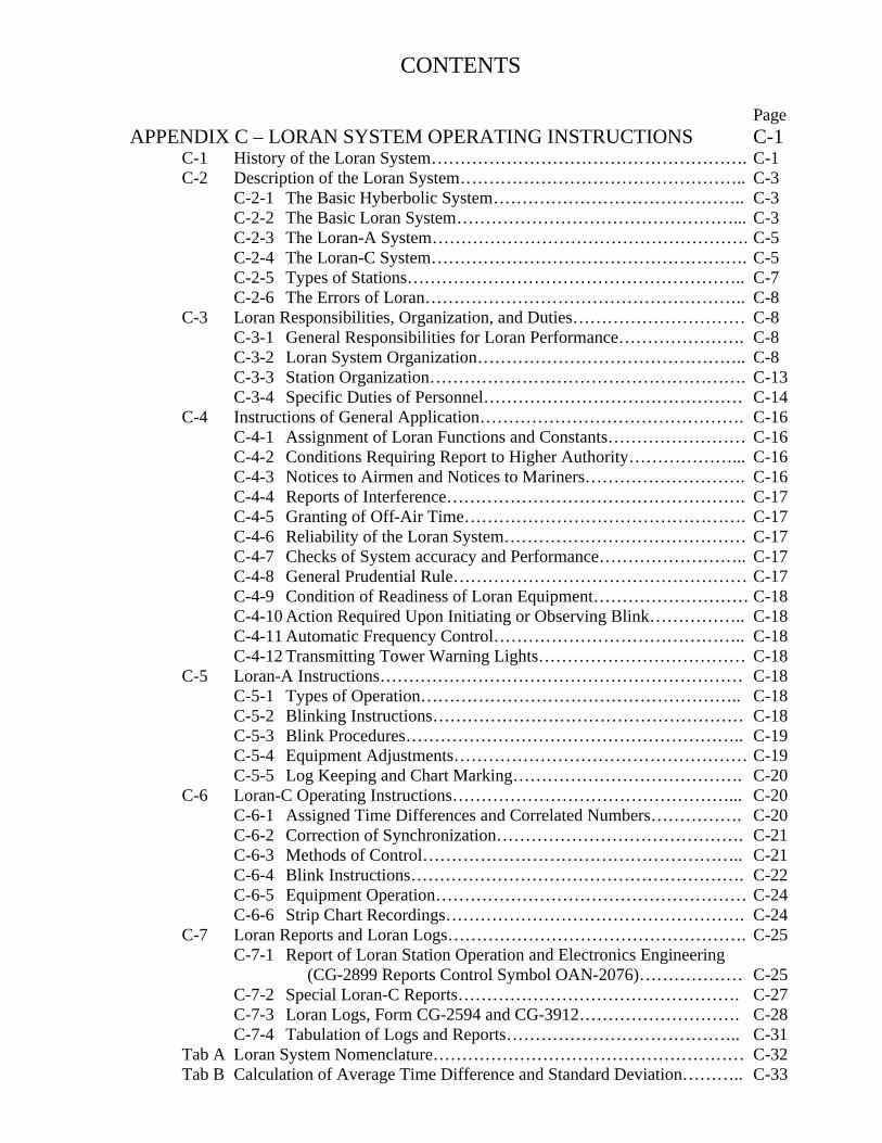
CONTENTS Page APPENDIX C – LORAN SYSTEM OPERATING INSTRUCTIONS C-1 C-1 History of the Loran System………………………………………………. C-1 C-2 Description of the Loran System………………………………………….. C-3 C-2-1 The Basic Hyberbolic System…………………………………….. C-3 C-2-2 The Basic Loran System…………………………………………... C-3 C-2-3 The Loran-A System………………………………………………. C-5 C-2-4 The Loran-C System………………………………………………. C-5 C-2-5 Types of Stations………………………………………………….. C-7 C-2-6 The Errors of Loran……………………………………………….. C-8 C-3 Loran Responsibilities, Organization, and Duties………………………… C-8 C-3-1 General Responsibilities for Loran Performance…………………. C-8 C-3-2 Loran System Organization……………………………………….. C-8 C-3-3 Station Organization………………………………………………. C-13 C-3-4 Specific Duties of Personnel……………………………………… C-14 C-4 Instructions of General Application………………………………………. C-16 C-4-1 Assignment of Loran Functions and Constants…………………… C-16 C-4-2 Conditions Requiring Report to Higher Authority………………... C-16 C-4-3 Notices to Airmen and Notices to Mariners………………………. C-16 C-4-4 Reports of Interference……………………………………………. C-17 C-4-5 Granting of Off-Air Time…………………………………………. C-17 C-4-6 Reliability of the Loran System…………………………………… C-17 C-4-7 Checks of System accuracy and Performance…………………….. C-17 C-4-8 General Prudential Rule…………………………………………… C-17 C-4-9 Condition of Readiness of Loran Equipment……………………… C-18 C-4-10 Action Required Upon Initiating or Observing Blink…………….. C-18 C-4-11 Automatic Frequency Control…………………………………….. C-18 C-4-12 Transmitting Tower Warning Lights……………………………… C-18 C-5 Loran-A Instructions……………………………………………………… C-18 C-5-1 Types of Operation……………………………………………….. C-18 C-5-2 Blinking Instructions……………………………………………… C-18 C-5-3 Blink Procedures………………………………………………….. C-19 C-5-4 Equipment Adjustments…………………………………………… C-19 C-5-5 Log Keeping and Chart Marking…………………………………. C-20 C-6 Loran-C Operating Instructions…………………………………………... C-20 C-6-1 Assigned Time Differences and Correlated Numbers……………. C-20 C-6-2 Correction of Synchronization……………………………………. C-21 C-6-3 Methods of Control……………………………………………….. C-21 C-6-4 Blink Instructions…………………………………………………. C-22 C-6-5 Equipment Operation……………………………………………… C-24 C-6-6 Strip Chart Recordings……………………………………………. C-24 C-7 Loran Reports and Loran Logs……………………………………………. C-25 C-7-1 Report of Loran Station Operation and Electronics Engineering (CG-2899 Reports Control Symbol OAN-2076)……………… C-25 C-7-2 Special Loran-C Reports…………………………………………. C-27 C-7-3 Loran Logs, Form CG-2594 and CG-3912………………………. C-28 C-7-4 Tabulation of Logs and Reports………………………………….. C-31 Tab A Loran System Nomenclature……………………………………………… C-32 Tab B Calculation of Average Time Difference and Standard Deviation……….. C-33
APPENDIX C
LORAN SYSTEM OPERATING INSTRUCTIONS
C-1 History of the Loran System In 1940, the U.S. Army Signal Corps proposed the following requirement for a “Precision Navigational equipment for Guiding Airplanes:” a. General: it is desired to have precision navigational equipment for guiding airplanes to a pre-determined point in space over or in an overcast by radio beams, detection apparatus, or direction finders. b. Distance: maximum possible, 500 miles desired. c. Altitude: the ceiling of present heavy bombers; about 35,000 feet. d. Accuracy: the greatest accuracy obtainable; 1000 feet at 200 miles is desired. Alfred L. Loomis, then chairman of the Microwave Committee, suggested, to the committee, a pulsed hyperbolic, radio grid-laying system which was accepted for investigation. The proposal involved the use of synchronized pulsed transmissions from pairs of stations separated by several hundreds of miles. The families of hyperbolic lines of constant time difference generated could be interpreted as lines of position by vehicles equipped with receiver-indicators capable of measuring the time differences. From this concept, the “LORAN” system was evolved. The word “LORAN” is an acronym, derived from the term ‘Long Range Aid to Navigation.” Contracts for receiver-indicators, timer (synchronizers) and transmitters were let to several companies although methods of synchronization and time difference measurement had not been determined. Original estimates of equipment availability suggested that tests might start in 1941. Administrative difficulties arose, however. By summer of 1941, a navigation group at the Massachusetts Institute of Technology Radiation Laboratory had assumed the project. This group considered the medium frequency range to be capable of greater range than the microwave frequencies as skywaves could be utilized.
A test pair of stations was established on the East Coast. They operated on a repetition rate of 33? pulses per second and were capable of transmitting on any frequency between 2.9 and 8.5 megacycles per second. A receiver indicator was installed on in a car. Tests conduced at sites as far west as Ohio indicated that the medium frequencies gave signal stability sufficient for long range navigational system and that a multiple trace indicator was required for time difference measurement. The latter conclusion was supported by information received from England concerning the GEE system, then under development. Work on the original microwave project was stopped. In 1941, the two original stations were synchronized through a monitor station which used a two-trace indicator. Synchronization of the transmitting stations and use of the two-trace indicator permitted tests of accuracy of position determination. A receiver in Bermuda yielded average errors of 2½ miles in readings taken on skywaves. During this period a method of changing repetition rates was developed which permitted several pairs of stations, transmitting on the same frequency, to be identified. By June 1942, new high powered transmitters were installed at the original stations at Montauk Point, L.I., and Fenwick Island, Del. The frequency used was 1950 kilocycles per second. This frequency gave good skywave stability at night. A second frequency, 7.5 mc. per second, was considered and tested for daytime use but this idea was dropped. The demand for the 2 mc. Transmitters was so great that the 7.5 mc. equipments could not be phased in to the construction. Also, the 2 mc. frequency was found to give better reception than the higher frequency. Meanwhile, joint Army-Navy requirements for the system had been defined and a four station, three line of position net was planned for full scale test in October 1942. The East Coast stations and two Canadian stations started regular service in that
month. The first shipboard receiver was installed on the battleship New York, also during October. By the end of 1942, about 45 receiving sets were in use. On January 1, 1943, the Coast Guard assumed responsibility for the East Coast stations. In June 1943 three new northern stations were turned over to the Coast Guard. Charts for the original four station chain were available in the spring of 1943. About 40 ships of the U.S. Navy and some Royal Canadian Navy ships were equipped with receivers. The Loran System was operational. During the remainder of the war, the Loran System expanded to meet the navigational requirement of the Allied forces. The use of Loran by ships and aircraft became common. Service area expended at the rate of 10 million square miles per year between 1942 and 1944. After 1944, with full acceptance of the system, expansion rate increased to 40 million square miles per year and maintained this level to the end of the war. By V-J Day the night-time service area covered about 70 million square miles. Part of the expansion was the result of the skywave synchronized (SS) Loran System installed for navigation over Germany and in the China-China sea-Japan area. Development of this system started in April 1943 using skywave synchronization between Fenwick Island and Bonavista, Newfoundland, some 1,100 mile. Line of position error of about 0.5 miles was observed. A four-station net was established in two pairs in the eastern United States. By October 1943 results of tests showed an average fix error of 1 to 2 miles was obtainable over the entire service area. Baselines of 1,200 to 1,300 miles were possible. Of course the system was limited to nighttime use. By 1944, three SS Loran stations were installed in North Africa and one in Scotland, providing night navigation over almost the whole European Continent. Some improvement in chart presentation and in skywave corrections helped win acceptance of the system. By 1945, SS Loran was in use nightly for bombing of the German homeland. Installations in the China-Burma-India theater were made in 1945 to provide one line of position over the Hump to China. Several pacific chains utilized skywave synchronization at night and groundwave synchronization by day.
In 1944 studies of propagation at 170 and 180 kc. per second were began. In April 1945, three stations were established to investigate Loran operation at 180 kc. per second. This LF (low frequency) Loran used superposition matching methods, as did the other Loran systems, which because of the complex form of the envelope resulting from groundwave and skywave mixing, were unsuitable. Additional matching of individual cycles was tested. Difficulty in selecting the proper cycles made the system unacceptable and it was discontinued. Accuracy in the order of 160 feet at 750 miles had been demonstrated. In 1946, work was resumed in an atempt[sic] to refine the cycle match and a system named CYCLAN evolved. Two frequencies were used to prevent ambiguities. Interference problems and the assignment of the 90-100 per second band to long-range radio navigation systems killed the CYCLAN development. In 1952, a long range, automatic, ground reference tactical bombing system was developed. Pulsed hyperbolic transmissions in the 90-100 kc. band were an integral part of it. Time difference measurements were obtained in the order of a few tenths of a microsecond. In 1957, the hyperbolic features of this system were used in the development of a high accuracy, long range Loran system. The Coast Guard assumed operation of the three stations, located on the East Coast, in 1958. Peak powers of 60 kw. from each station resulted in ranges of 1,500 miles for the groundwave, 2,300 miles for the first hop skywave and up to 3,435 miles for subsequent skywaves. Accuracy of 250 feet or less over more than one million squares was obtained. This system, designated Loran-C, has since grown to 7 chains comprised of 25 stations. An attempt to apply Loran-C time difference measurement techniques to the 2 mc. Loran was made in 1958 with notable success. A two frequency MW-HF Loran was developed and tested in 1944. Synchronization was maintained with the mc. skywaves at night. By day service was furnished by the 2 mc. signals which were cynchronized[sic] by transmissions on 10.585 mc. The system was sound and increased usable baseline lengths but frequency allocations could not be obtained.

In foregoing history, several Loran systems have been discussed. To prevent confusion, in 1957 and more recently, letter designations and definitions were assigned as follows: Loran-A—2 mc. per second envelope matching Loran (previously known as Standard Loran). Loran-B—2 mc. per second envelope matching Loran supplemented by cycle phase matching within the envelope. Loran-C—100 kc. per second envelope matching Loran supplemented by cycle phase matching within the envelope. Loran-D—Short baseline 100 kc. per second envelope matching Loran supplemented by cycle phase matching within the envelope. Loran-E—MF-HF envelope matching Loran with skywave synchronization and/or match. Only Loran-A and Loran-C are presently operational. Loran-D is a recently conceived application of Loran-C. The Coast Guard has been the prime operator of the Loran System because of its historic and legal role in the aids to navigation field. The Loran System has become a common, highly useful and valued aid to navigation because it is reliable and accurate. Our job is to keep the Loran System reliable and accurate through proper operation and maintenance. The Loran System fills the varied and demanding requirements of safe navigation. We must see that it continues to meet this need. C-2 Description of the Loran System C-2-1 THE BASIC HYPERBOLIC SYSTEM The hyperbolic electronic systems for navigation are based on an elementary principle of mathematics, the hyperbola. Hyperbolic systems do not directly measure terrestrial quantities to determine position. The hyperbola is the locus of all points whose difference in distance from two foci is constant. Since the velocity of propagation of electromagnetic radiation in the atmosphere is nearly constant, time of receipt of an electromagnetic pulse is directly proportional to the distance traveled by the pulse using the basic relationship, distance equals velocity times time. Thus, time can be substituted for distance. With
the advent of precise pulsing techniques, the electronics industry was able to adapt this principle as an aid to navigation. The difference in time of receipt of pulses from two synchronized transmitting stations can be measured by the user on a special receiver designed for this purpose. This difference in time describes one hyperbola of which the transmitting stations are the foci. This hyperbola is called the hyperbolic line of position. Measurement of a second time difference between pulses of a second pair of synchronized transmitting stations establishes another line of position, which results in a fix. Hyperbolic systems use one of transmission patterns, either CW or pulsed. In the continuous wave (CW) system, hyperbolic information is extracted from the phase information of the transmission. This system leads to ambiguities, as there is no means of identifying particular points of constant phase difference. Phase difference readings are repeated in successive hyperbolic lanes. A system of lane identification is required, which increases the complexity of the system. Otherwise, the receiver must be preset to a known location. The pulsed system eliminates the problem of ambiguity arising from lane similarity. Proper synchronization of a pulsed system reduces remaining ambiguities to operationally acceptable levels. Accuracy identical to that of the continuous wave system may be obtained by extracting phase information from the cycles within the pulse. Both systems are subject to skywave contamination, but the pulsed system is affected to a lesser extent. C-2-2 THE BASIC LORAN SYSTEM. The basic loran element is the pair. Two transmitting stations must be highly synchronized to develop useful hyperbolic information. The accuracy and reliability of the hyperbolic system depends on the combined efforts of the two transmitting stations. To synchronize the two stations in a pair the general practice is to to designate the “master” station and have it control the loran transmitting sequence. The other station then slaves its transmission to the master and is called the “slave” station. Through synchronization, a common time base has been
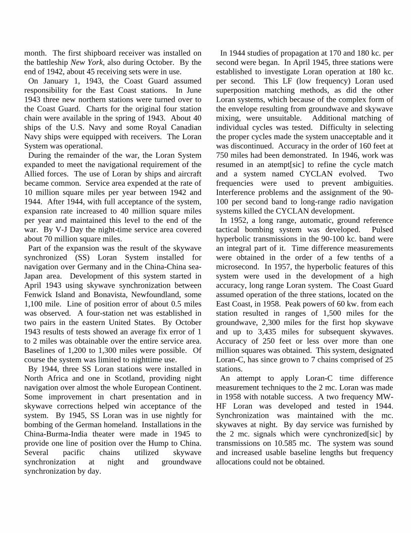
established on which the stations operate. Consider a pair of loran stations M and S as shown in figure C-1. Assume that they transmit simultaneously. Since point A is on the perpendicular bisector of the baseline, distances MA and SA are equal and travel time of the radio waves over these paths will be equal. Therefore, the time difference of receipt of signals from M and S equals zero. At point B the time difference will be MB-SB, while at point C the time difference will be MC-SC. Similar analysis can be
made in the case of points D and E. Note that the time difference magnitude observed at points B and C may be equal. Since points B and C are on different hyperbolic lines and yet may still measure the same time difference, an ambiguity exists. Ambiguity also exists between points D and E. Therefore, the system, with both stations transmitting simultaneously, is ambiguous. Identical time differences occur on either side of the perpendicular bisector. To remove this ambiguity, delay the transmission of one station. Referring to figure C-1, the master station M initiates the transmission sequence. The slave station S transmits precisely at the time that the master signal is received at the slave. Since the master initiates the sequence, time difference expressions must be developed by measuring signal paths from the master station. The time difference read at point A will now be MS+SA-MA. This is no longer zero. The time difference at point B will be MS+SB-MB, at point C it will be MS+SC-MC. The time difference for point B is now larger than for point C. The time difference at point E will be MS+SE=ME. But since ME equals MS+SE, the time difference at point E is zero. The time difference for point D is MS+SD-MD, where SD equals MS+MD, so this time difference
equals 2MS. By delaying transmission of the slave signal, there has been established a time difference pattern with minimum value at the slave and increasing to maximum at the master. Practically, this transmission sequence is unusable because the slave’s local signal would prevent reception of the master signal through receiver blocking and hence prevent synchronization. This difficultly can be eliminated by delaying the slave transmission an additional amount called coding delay. The coding delay is inserted after reception of the master signal at the slave station. Its effect is to make the minimum time difference, occurring at the slave, equal to the coding delay. All time differences are increased by a like amount. The hyperbolic pair is now sequenced for practical operation and contains no ambiguities. The following specific time difference information is applicable. The minimum time difference reading occurs on the slave baseline extension and is equal to the coding delay. The maximum time difference reading occurs on the master baseline extension and is equal to twice the baseline travel time plus the coding delay, or 2MS+coding delay, in our notation. The foregoing discussion has been made in practical terms to illustrate the method of time difference calculation. The general time difference formula is derived in the same manner and is: TD = B + ? + K (L? - Lũ) Where B = baseline length in microseconds or B = K times baseline length in nautical miles ? = coding delay K = 6.18 microsecond/nautical mile L? = distance from point to slave in nautical miles Lũ = distance from point to master in nautical miles The accuracy of the Loran line of position obtained from a particular Loran pair will depend on geometric accuracy, synchronization accuracy, and equipment
accuracy. Geometric accuracy is determined by baseline length and position of the receiver to the baseline. The longer the baseline, the greater the area of high accuracy, as there is less curvature of the hyperbolas in the vicinity of the baseline. Accuracy at positions remote from the baseline is better in the vicinity of the perpendicular bisector than it is near the baseline extension due to the curvature of the hyperbolas. Synchronization accuracy depends on the accuracy of the transmitted signal and on the constancy of the time difference reading at a particular point in the hyperbolic pattern. Equipment accuracy is a function of equipment design and maintenance. Geometric accuracy is fixed at the time of station construction; equipment accuracy is limited by design. Loran operating and maintenance procedures are designed to maintain the highest possible synchronization and equipment accuracy. Loran systems are defined in terms of frequency, pulse shape, repetition rate, and coding delay. Definitions of these parameters are common to all Loran systems and are listed below. a. Frequency. Loran frequency is chosen to give the most ground wave coverage in the allocated frequency band. b. Pulse shape. Pulse shape is designed to give the fastest possible rise time with the authorized bandwidth. c. Repetition rate. Pulse repetition rate (number of pulses per second) is used to assist in identification of the station pair and to reduce mutual interference between rates. The reciprocal, pulse repetition period, is derived from the basic oscillator frequency. It is chosen to allow operation on the longest baseline desired. d. Coding delay. Coding delay is the time between reception of the master’s signal by the slave, and the slave’s transmission. It is necessary to remove ambiguity, provide slave identification, and establish the presentation of the signals on the receiver. C-2-3 THE LORAN-A SYSTEM. The Loran-A system operates in the frequency band of 1750-1950 kc. At present three frequencies channels are in use; channel 1, 1950 kc.; channel 2, 1850 kc., channel 3, 1900 kc. Channel 4, 1750 kc., was discontinued after
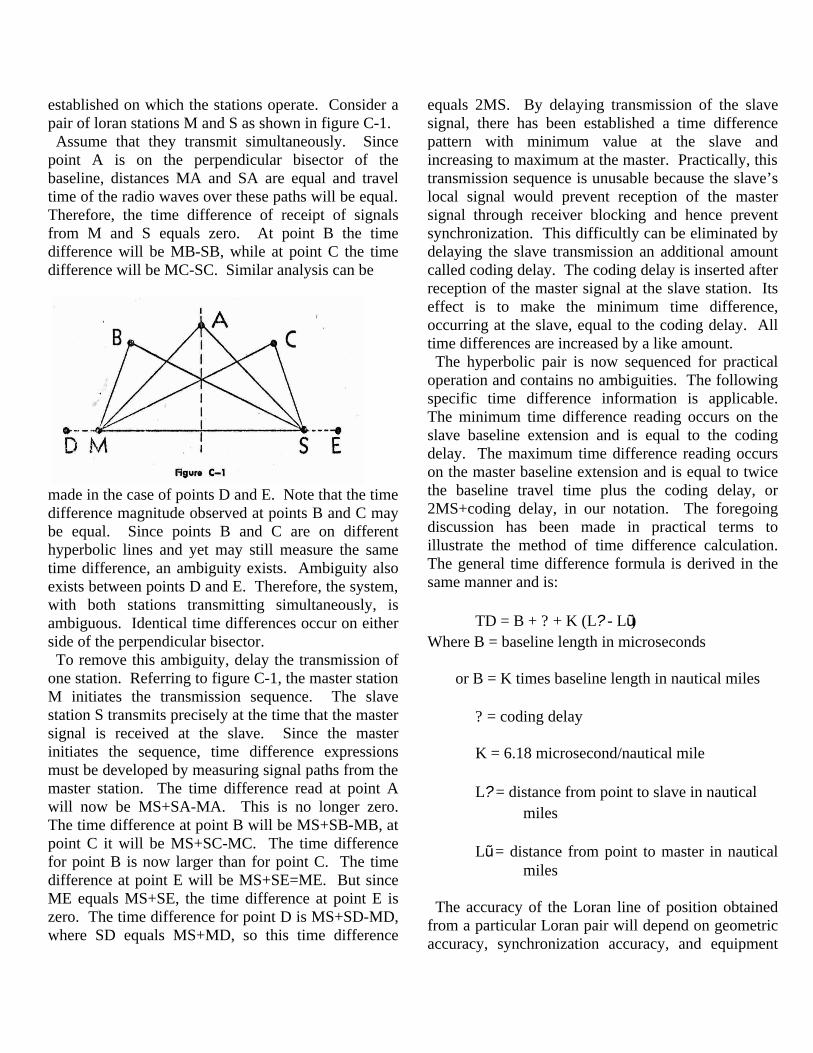
World War II. Each station transmits one pulse per loran sequence. Each pair is assigned a specific pulse repetition rate. Specific pulse repetition rates (PRR) are derived from three basic repetition rates of 20, 25 and 33? pulses per second. These rates are designated (S), (L), and (H) respectively. The corresponding repetition periods are 50,000, 40,000, and 30,000 microseconds. Specific repetition periods for specific PRR’s 0 through 7 are derived by subtracting multiples of 100 microseconds from the basic repetition periods. The following table illustrates all Loran-A specific repetition periods.
TABLE C-1 LORAN-A SPECIFICATION REPETITION PERIODS
Basic PRR . Specific PRR S L H 0 …………………… 50,000 40,000 30,000 1 …………………… 49,900 39,900 29,900 2 …………………… 49,800 39,800 29,800 3 …………………… 49,700 39,700 29,700 4 …………………… 49,600 39,600 29,600 5 …………………… 49,500 39,500 29,500 6 …………………… 49,400 39,400 29,400 7 …………………… 49,300 39,300 29,300 Loran-A pairs are designated by frequency channel, basic repetition rate, and specific repetition period in that order. For example, 1L3 denotes a Loran-A pair having a frequency of 1950 kc., a basic repetition rate of 25 cycles per second, and a specific repetition period of 39, 700 microseconds. The Loran-A pulse shape is a cosine squared pulse and is defined in terms of rise time and pulse width. Rise time is measured from the 10- to the 90-percent amplitude points of the leading edge and the pulse width is measured at 50-percent amplitude. Specifications are: Low High Power Power* RISE TIME 20±1 us 21±1 us 21±1 us 20±1 us PULSE WIDTH 40±1 us 42±1 us
*Note: A field change is under preparation which will modify the high power pulse forming network so that the high power pulse will be identical to the low power pulse. Loran-A uses a two-trace presentation. Each trace contains one-half of the pulse repetition period (neglecting flyback time). To accommodate the station transmissions to this presentation, it is necessary to delay the slave transmission by one-half the pulse repetition period after receipt of the master signal. This delay period is referred to as the reference delay. The coding delay as described in section C-2-2 for Loran-A consists of this reference delay and a finite delay of 1000 or 500 microseconds. This finite delay provides for positive identification in that when the left hand signal appears on the upper trace, the left hand signal is the master. In time difference measurement the reference delay is automatically subtracted out by the split trace nature of the presentation. The finite delay is the least obtainable time difference reading on any Loran-A pair; hence, it is called the “coding delay” in Loran-A. Loran-A stations are arranged in pairs with baselines of from 200 to 700 miles. Specific rates are selected to provide freedom from interference from other pairs. Since fix coverage is normally required, a third station is provided to form a second pair, resulting in a loran triad. The common station operates on both specific repetition rates, performing either double or mixed functions. Where possible, due to site availability, addition coverage is added by adding pairs to existing chains. C-2-4 THE LORAN-C SYSTEM. Loran-C is a multiple, hyperbolic navigation system operating in the 90-110 kc. frequency band. The term multipulse is used to connote transmission of groups of pulses in each repetition period versus the Loran-A technique of transmitting a single pulse per station in each repetition period. The advantages of multipulse operation are increased radiated power from each transmitting, i.e. eight pulses per period versus one pulse per period, and provision of a unique identification code for each type of station by changing phase of the pulses and pulse groups.
The pulse changing of the Loran-C pulses is an important aspect of system operations. Phase changing, commonly called phase coding, merely indicates that the phase information within the pulse envelope is changed from pulse to pulse and pulse group to pulse group in a prearranged sequence. The sequence in use was derived so as to provide the following: a. Automatic detection of master and slave signals such that receivers can synchronize on signals which could not be visually identified. b. Protection against skywave contamination from pulse to pulse, i.e., a skywave from the first pulse overlapping the second pulse. c. Rejection of certain interfering signals. In order to provide automatic detection of a master signal, master station phase codes are different from the slave station codes. Phase code patterns used in the Loran-C System are shown below:
TABLE C-2 PHASE CODING
MASTER PULSES WITHIN GROUP 1 2 3 4 5 6 7 8 1st ………….. 0 0 180 180 0 180 0 180 2nd …………. 0 180 180 0 0 0 0 0 3rd ………….. repeat 1st 4th ………….. repeat 2nd SLAVE PULSES WITHIN THE GROUP (all slaves)
1 2 3 4 5 6 7 8 1st ………….. 0 0 0 0 0 180 180 0 2nd …………. 0 180 0 180 0 0 180 180 3rd ………….. repeat 1st 4th ………….. repeat 2nd The ninth pulse of the master transmission is used to aid visual identification for receiver lock on and also to indicate system malfunction or instability by blinking on and off in defined sequence. Blink procedures are outlined in separate portions of this manual. Loran-C techniques provide for two to four slave stations operating with a single master station. Station
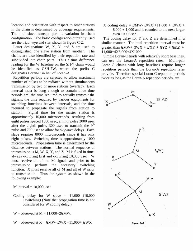
location and orientation with respect to other stations in the chain is determined by coverage requirements. The multislave concept permits variation in chain configuration. The basic configuration currently used are the triad, wye and star, shown in figure C-2. Letter designations W, X, Y, and Z are used to distinguished one slave station from another. The chains are also identified by their repetition rate and subdivided into chain pairs. Thus a time difference reading for the W baseline on the SH-7 chain would be identified as CSH-7W, where the prefix C designates Loran-C in lieu of Loran-A. Repetition periods are selected to allow maximum number of pulses to be radiated without simultaneous transmission by two or more stations (overlap). Each interval must be long enough to contain three time periods are: the time required to actually transmit the signals, the time required by various equipments for switching functions between intervals, and the time required to propagate the signals from station to station. Signal time for the master station is approximately 10,000 microseconds, resulting from eight pulses spaced 1000 usec, a ninth pulse 2000 usec after the eighth pulse, 300 usec to transmit the 9th pulse and 700 usec to allow for skywave delays. Each slave requires 8000 microseconds since it has only eight pulses. Switching time is approximately 1000 microseconds. Propagation time is determined by the distance between stations. The normal sequence of transmission is M, W, X, Y, and Z. M is fixed in time, always occurring first and occurring 10,000 usec. W must receive all of the M signals and prior to its transmission perform the necessary switching function. X must receive all of M and all of W prior to transmission. Thus the system as shown in the following example: M interval = 10,000 usec Coding delay for W slave = 11,000 (10,000 +switching) (Note that propagation time is not considered for W coding delay.) W = observed at M = 11,000+2ßMW. W = observed at X = ßMW- ßWX +11,000+ ßWX
X coding delay = ßMW- ßWX +11,000 + ßWX + 8,000 + 1,000 and is rounded to the next larger even 1000 usec. The coding delay for Y and Z are determined in a similar manner. The total repetition interval must be greater than ßMW+ ßWX + ßXY + ßYZ + ßMZ + 11,000+4X8,000+4X1000. Simple Loran-C triads with relatively short baselines, can use the Loran-A repetition rates. Multi-pair Loran-C chains with long baselines require longer repetition periods than the Loran-A repetition rates provide. Therefore special Loran-C repetition periods twice as long as the Loran-A repetition periods, are
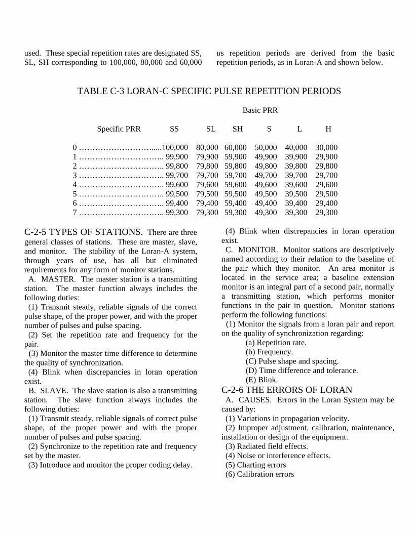
used. These special repetition rates are designated SS, SL, SH corresponding to 100,000, 80,000 and 60,000
us repetition periods are derived from the basic repetition periods, as in Loran-A and shown below.
TABLE C-3 LORAN-C SPECIFIC PULSE REPETITION PERIODS Basic PRR Specific PRR SS SL SH S L H 0 ……………………….....100,000 80,000 60,000 50,000 40,000 30,000 1 ………………………….. 99,900 79,900 59,900 49,900 39,900 29,900 2 ………………………….. 99,800 79,800 59,800 49,800 39,800 29,800 3 ………………………….. 99,700 79,700 59,700 49,700 39,700 29,700 4 ………………………….. 99,600 79,600 59,600 49,600 39,600 29,600 5 ………………………….. 99,500 79,500 59,500 49,500 39,500 29,500 6 ………………………….. 99,400 79,400 59,400 49,400 39,400 29,400 7 ………………………….. 99,300 79,300 59,300 49,300 39,300 29,300 C-2-5 TYPES OF STATIONS. There are three general classes of stations. These are master, slave, and monitor. The stability of the Loran-A system, through years of use, has all but eliminated requirements for any form of monitor stations. A. MASTER. The master station is a transmitting station. The master function always includes the following duties: (1) Transmit steady, reliable signals of the correct pulse shape, of the proper power, and with the proper number of pulses and pulse spacing. (2) Set the repetition rate and frequency for the pair. (3) Monitor the master time difference to determine the quality of synchronization. (4) Blink when discrepancies in loran operation exist. B. SLAVE. The slave station is also a transmitting station. The slave function always includes the following duties: (1) Transmit steady, reliable signals of correct pulse shape, of the proper power and with the proper number of pulses and pulse spacing. (2) Synchronize to the repetition rate and frequency set by the master. (3) Introduce and monitor the proper coding delay.
(4) Blink when discrepancies in loran operation exist. C. MONITOR. Monitor stations are descriptively named according to their relation to the baseline of the pair which they monitor. An area monitor is located in the service area; a baseline extension monitor is an integral part of a second pair, normally a transmitting station, which performs monitor functions in the pair in question. Monitor stations perform the following functions: (1) Monitor the signals from a loran pair and report on the quality of synchronization regarding: (a) Repetition rate. (b) Frequency. (C) Pulse shape and spacing. (D) Time difference and tolerance. (E) Blink. C-2-6 THE ERRORS OF LORAN A. CAUSES. Errors in the Loran System may be caused by: (1) Variations in propagation velocity. (2) Improper adjustment, calibration, maintenance, installation or design of the equipment. (3) Radiated field effects. (4) Noise or interference effects. (5) Charting errors (6) Calibration errors
B. EFFECTS. A brief description of the effect of various system errors follows: (1) VARIATIONS IN PROPAGATION VELOCITY. Differences in the conductivity and density of the media through which a radio wave travels, and over which it passes, cause variations in the velocity of propagation. Also the apparent velocity of the phase of the radio frequency cycles is different from the velocity of the pulse envelope. These variations of velocity cause observed time difference readings to differ from readings computed with a single value of velocity and conductivity. The variations between envelope and phase time difference is called “discrepancy”. (2) EQUIPMENT ERRORS. The accuracy and repeatability of Loran readings is first a function of design and installation; and second a function of maintenance and adjustment by personnel. Loran operation depends upon both local and remote signals following common circuits, and under-going identical delays between reception at the antenna, and measurement in the timer. Further it depends on identical response of indicating circuits. Neither can be obtained without proper installation and maintenance. (3) RADIATED FIELD EFFECT. Near a transmitting station errors arise due to the presence of the induction field. Variations in this error occur when conductivity at the transmitting station changes, with precipitation or change in the water plane level. (4) IMPROPER OPERATING PROCEDURES. These are primarily personnel errors and must be eliminated by training, supervision and promulgation of improved procedures. (5) NOISE AND INTERFERENCE. The effects of these factors are reduce by proper equipment design, operation and maintenance. C. CORRECTION. Correction of the errors at a station is an engineering matter when they arise from design or installation. It is a personnel matter when errors arise from operation or maintenance. It is a management matter when the operating instructions are incorrect. Generally the errors from the above sources are easy to detect and correct.
Errors from the remaining sources, however, are difficult to assess and correct. So the Loran System allows them to remain and adjust tolerances, delay, or equipment to continue operation. The accuracy and reliability of the system depends on how rapidly and to what extent we make these adjustments. C-3 Loran responsibilities, Organization and Duties C-3-1 GENERAL RESPONSIBILITIES FOR LORAN PERFORMANCE. Loran is important; the need for the highest level of operational performance of each Loran station, of each Loran pair, of each Loran chain is needed to satisfy the demands placed on the Loran System. System performance is a function of fulfillment of individual responsibilities of the personnel concerned. This chapter will outline the general organization of the Loran System and will detail the duties and responsibilities of the station personnel. C-3-2 LORAN SYSTEM ORGANIZATION. Three areas of responsibility exist within the Loran System. They are command, operational control, administrative and technical control. Since the Loran System consists of field stations furnishing a service to users, the primary area of responsibility is operations. This is reflected in the fact that the important decisions affecting the system are considered to be operational. The electronic nature of the system necessitates the inclusion of a large area of technical responsibility. The isolated, or semi-isolated character of most Loran stations increase technical responsibility through the problems of station maintenance and power generation. Administrative responsibilities are required, as well all operating units, to fulfill the personnel and supply needs of the system. The technical and administrative responsibilities are exercised in support of operations. The basic organizational element in the Loran System is the station. Stations are organized into pairs; each pair operating on a specific repetition rate. Pairs are further arranged to operate in chains which provide navigation service over a particular
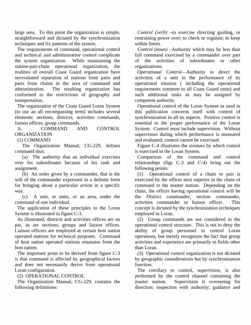
large area. To this point the organization is simple, straightforward and dictated by the synchronization techniques and fix patterns of the system. The requirements of command, operational control and technical and administrative control complicate the system organization. While maintaining the station-pair-chain operational organization, the realities of overall Coast Guard organization have necessitated separation of stations from pairs and pairs from chains in the area of command and administration. The resulting organization has conformed to the restrictions of geography and transportation. The organization of the Coast Guard Loran System (to use an all encompassing term) includes several elements: sections, districts, activities commands, liaison offices, group commands. A. COMMAND AND CONTROL ORGANIZATION (1) COMMAND The Organization Manual, CG-229, defines command thus: (a) The authority that an individual exercises over his subordinates because of his rank and assignment. (b) An order given by a commander, that is the will of the commander expressed in a definite form for bringing about a particular action in a specific way. (c) A unit, or units, or an area, under the command of one individual. The application of these principles to the Loran System is illustrated in figure C-3. As illustrated, districts and activities offices are on par, as are sections, groups and liaison offices. Liaison officers are employed at certain host nation operated stations for technical purposes. Command of host nation operated stations emanates from the host nation. The important point to be derived from figure C-3 is that command is affected by geographical factors and does not necessarily derive from operational Loran configuration. (2) OPERATIONAL CONTROL The Organization Manual, CG-229, contains the following definitions:
Control (verb) –to exercise directing guiding, or restraining power over; to check or regulate; to keep within limits. Control (noun) –Authority which may be less than full command exercised by a commander over part of the activities of subordinates or other organizations. Operational Control—Authority to direct the activities of a unit in the performance of its operational mission ( including the operational requirements common to all Coast Guard units) and such additional tasks as may be assigned by competent authority. Operational control of the Loran System as used in this publication concerns itself with control of synchronization in all its aspects. Positive control is essential to the proper performance of the Loran System. Control must include supervision. Without supervision during which performance is measured and evaluated, control cannot be exercised. Figure C-4 illustrates the avenues by which control is exercised in the Loran System. Comparison of the command and control relationships (figs C-3 and C-4) bring out the following points: (1) Operational control of a chain or pair is exercised by the officer next superior in the chain of command to the master station. Depending on the chain, the officer having operational control will be the District commander, section commander, activities commander or liaison officer. This concept is dictated by the synchronization techniques employed in Loran. (2) Group commands are not considered in the operational control structure. This is not to deny the ability of group personnel to control Loran operations, but merely recognizes the fact that group activities and experience are primarily in fields other than Loran. (3) Operational control organization is not dictated by geographic considerations but by synchronization function. The corollary to control, supervision, is also performed by the control channel containing the master station. Supervision is overseeing for direction; inspection with authority; guidance and

instruction with immediate responsibility for performance; superintendence or leading. Control and supervision become more critical at each lower echelon. The Commandant exercises
general control and supervision over the whole Loran System. District commanders and section commanders control and supervise chains under their cognizance in more detail. The commanding officer of a designated station performs as chain (or pair)
operations control officer and is responsible for minute to minute control and supervision of all stations in chain synchronization. His duties are outlined in paragraph C-3-2C. Each station commanding officer is responsible for the control and supervision of the performance of his station in the synchronization of the chain or pair. (3) Technical and Administrative control. The Organization Manual, CG-229 contains the following definitions: Control, administrative—Authority to direct the logistic activities of a unit in fiscal, supply, engineering and personal matters. Control, technical—The specialized or professional guidance and direction exercised in technical matters. Both types of control are exercised through the command channels shown in C-3. B. CHAIN COMMANDER The term “chain commander” is in general use, but has received official recognition in only one Loran-C chain. It is not intended that a “chain commander” should be designated for each chain, nor is it considered necessary. In fact, the term is contradictory because it is used to identify a person in the structure of operational control, not in the chain of command. The function of chain command, as it has been used to date, is performed by the echelon having direct operational control of the master station. C. CHAIN (OR PAIR) OPERATIONAL CONTROL OFFICER (1) The officer having operational control of a Loran-C chain shall designate a chain operational control officer for the chain. The commanding officer, or officer-in-charge of a Loran-A master station will be the pair operations officer for the pair(s) of which his station is a part. The chain (or pair) operations control officer is the “on the spot” representative of the officer having operational control of the chain or pair and is responsible to that officer for the operational performance of the chain or pair. The duties of the chain (or pair) operations control office include:
(a) Familiarizing himself with the system operation of the chain or pair, the functions of the station therein, the assigned time differences and tolerances and the communication channels. (b) Keeping himself fully informed as to the quality and peculiarities of synchronization and the performance of all stations of their functions in synchronization. (c) Keeping the officer to whom he is responsible informed as to the quality and peculiarities of synchronization. (d) Recommending to the officer to when he is responsible, ways to improve the operations of the chain (or pair). (e) As the representative of the officer in operational control, making decisions and ordering actions in the chain or pair to regain and/or stabilize synchronization when time or circumstances do not permit him to contact the officer in operational control. (f) Collecting and tabulating such data from his station and from the other stations as he requires to enable him to perform these duties. (g) Reporting to the officer in operational control conditions in the chain or pair which are detrimental to synchronization and recommending corrective action. (h) Such other duties as may be assigned to him as chain (or pair) operations control officer by the officer in operational control. The authority of the chain (or pair) operational control officer extends only to those matters concerning synchronization. It does not extend to matters of internal administration at the other stations of the chain or pair. (2) Normally the master station is best for chain operations control point. The ability of the master station to function as the control point for operations derives from its inherently good monitoring capabilities. By its position in the chain or pair the master is most likely to be able to monitor all its associated pairs. (3) In the event that chain reconfiguration is necessary due to damage, the officer in operational control may, if necessary, reassign the duties of the chain operations control office.

D. ADSSIGNMENT OF RESPONSIBILTY (1) Responsibilities for command and control of Loran units are vested in the following command of staff elements: Command …………………..Commandant. District Commander. Section Commander. Group Commander. Station Commanding Officer or OINC Operational Control...............Commandant (O). District (o). Section Commander. Chain (or Pair) Operations Control Officer. Other commanding officers or OINC’s., Technical Control…...………Commandant (E). District (e). Section Commander engineer- ing staff. Station commanding officer or OINC. Administrative Control……..Commandant (F, E, and P) District (f,e,and p) Section Commander and Sec- tion staff Group Commander, Station Commanding Officer or OINC (2) Immediate responsibility for all phases of station command and control is the direct responsibility of the commanding officer or officer-in-charge.
C-3-3 STATION ORGANIZATION. Section 10-1-1 of CG-300, US Coast Guard Regulations, specifies in general the organization of a Coast Guard shore unit. A. TYPICAL ORGANIZATION. At any Loran station the station organization must support the primary mission of the station. Figure C-5 illustrates a typical station organization. B. PERSONNEL ALLOWANCE AND ORGANZATION. It is assumed that the personnel allowed will be sufficient to operate the station, maintain and support it. The great variation in allowances precludes detailing organizations for all Loran stations. The organization described herein is designed for the overseas Loran-C stations with large allowances; it is generally applicable to all Loran station. Small stations should adhere to the principles of the illustrated organization, combining functions as necessary. To the extent practicable all station personnel should be trained in the duties of Loran watchstander and other evolutions important to the Loran mission, for example, switching generators. This training will provide flexibility and assist in maintaining operational capabilities in case of personnel shortage or emergency conditions.

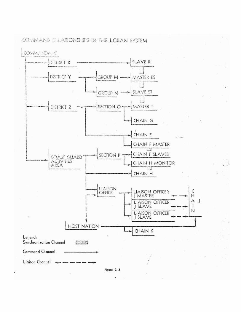
C. DIVISION ORGANIZATION (1) LORAN OPERATING DIVISION. The organization of the Loran Operating Division which is illustrated in figure C-6 has been evolved during actual operation. It provides the rotation of personnel between maintenance and watchstanding which in turn provides flexibility and training opportunity. It allows constant availability and assigned responsibility of watchstanding and maintenance personnel to insure rapid corrective action and compliance with safety requirements. (2) ADMINISTRATIVE AND ENGINEERING DIVISIONS. The commanding officer shall provide security and generator watches from these divisions. Further organization of these divisions shall provide for all functions of the station not assigned to the Loran operating division. C-3-4 SPECIFIC DUTIES OF PERSONNEL
The following specific assignments and duties are required in addition to duties or assignments which may be made by the commanding officer. Where a small complement is assigned, assignments and duties may be combined. A. COMMAND PERSONNEL (1) COMMANDING OFFICER. The regulations applying to the commanding officer of any unit are contained in chapter 7, part 1, of CG-300, U.S. Coast Guard Regulations. The commanding officer is assigned by the Commandant to administer the unit and to lead it in the performance of its mission. It is expected that the commanding officer will use his experience, education, and military authority to accomplish his mission. His lack of technical training in electronics, or the presence of technically trained personnel, does not modify this responsibility. Similarly, a technically
trained commanding officer is not released from his military responsibilities by reason of his training. (2) SECOND SENIOR OFFICER. The second senior officer will prepare himself to assume command in the absence of the commanding officer.
He will prepare himself to exercise disciplinary authority as specified by the District commander during such absence. He shall perform all duties assigned to him by virtue of his rating or specialty.
B. LORAN OPERATING PERSONNEL (1) SENIOR TECHICAL OFFICER (Radio Electrician, where assigned). The senior technical officer shall: (a) Administer the operation, maintenance, and engineering of the Loran installation and training of Loran operating personnel to insure reliability and accuracy of Loran operations. (b) Inspect the electronics equipment and spaces and observe performance of Loran operating personnel. (c) Review all logs and reports required in connection with Loran operation, maintenance, and engineering. (d) Advise the commanding officer on technical aspects of station Loran operation and on performance of Loran personnel.
(2) SENIOR ELECTRONICS TECHNICIAN. When no senior technical officer is assigned, the senior electronics technician will perform the duties of that officer. The senior electronics technician shall: (a) Direct the watchstanding and maintenance functions of the Loran Operation Division. (b) Review the performance of the daily, weekly, monthly, etc., routine preventive maintenance and operators maintenance schedules. (c) Review and approve all logs and reports prepared in connection with Loran operation, maintenance, and engineering. (d) Direct the Integrated Spare Parts program.
(e) Supervise the installation, authorized modification, and special tests of electronic equipment. (3) SENIOR MAINTENANCE MAN. The senior maintenance man shall: (a) Direct and perform the preventive and corrective maintenance of the electronic equipment. (b) Train and quality personnel as maintenance men. (c) Prepare logs and reports required in connection with electronic equipment maintenance, installation and modification. (d) Maintain the Integrated Spare parts system in accordance with the publications pertaining thereto and the needs of the station. Direct the correction of spare parts publications and records, issuance of parts, and preparation of requisitions in support of the Integrated Spare Parts systems. Prepare the Electronics Installation Record. (4) MAINTENANCE MEN. Maintenance men are responsible for the performance of preventive and corrective maintenance under the direction of the senior maintenance man and performance of any other duty which may be assigned to them. (5) MAINTENANCE WATCH. The maintenance watch shall be stood by qualified maintenance men. The maintenance watch shall perform all corrective maintenance during the period of his watch. He shall notify the senior maintenance man when corrective maintenance is beyond his capability. He shall inform the commanding officer of any Loran irregularity which requires report to higher authority. (See par. C-4-2) The maintenance watch is required at all Loran stations to insure compliance with safety regulations requiring the presence of two persons during maintenance of electronic equipment. The commanding officer may prescribe the location and degree of readiness of the maintenance watch. When the maintenance watch is required to perform maintenance in an area where the Loran watchstander cannot function as a safety man, additional personnel must be provided to meet safety requirements. (6) SENIOR LORAN WATCHSTANDER. The senior Loran watchstander shall:
(a) Direct the Loran watchstander in performance of their duties and stand watch himself if necessary. (b) Train and qualify personnel as Loran watchstanders. (c) Prepare ands review logs and reports required in connection with Loran operations. (7) LORAN WATCHSTANDER. The Loran watchstander shall: (a) Perform operators maintenance and adjustments required. (b) Make all log and recording chart entries in accordance with instructions. (c) Advise the maintenance watch of all Loran irregularities requiring report to higher authority. (d) Call the maintenance watch when any electronic equipment fails or when he needs assistance. (e) Perform all other duties which are assigned to the Loran watch by proper authority. (8) LORAN DAYWORKERS. Aside from work which may be assigned to them, Loran dayworkers should endeavor to increase their knowledge of equipment, operation, and all aspects of maintenance. C. STATION OPERATING PERSONNEL (1) SENIOR ENGINEMAN. The senior engineman shall: (a) Direct, supervise, and perform generator test and maintenance to insure proper and reliable operation and readiness for immediate service of all power generating equipment. (b) Direct, supervise, and perform tests and maintenance of all other equipment for which the Engineering Division is responsible. (2) Other station operating personnel shall perform such duties as may be assigned to them. C-4 Instructions of General Application C-4-1 ASSIGNMENT OF LORAN FUNCTIONS AND CONSTANTS. Upon establishment of a Loran pair, or chain, the Commandant (OAN) shall make the following assignments and specifications:
a. Composition of the pair, or chain, and the role of each station therein, including master, slave and monitor functions. b. Methods of control, in order of priority, or type of operation, as applicable, to be employed in each Loran pair. c. The repetition rate, coding delay, pulse spacing, standard time differences, controlling standard time difference, envelope to cycle discrepancies and tolerances, as applicable, to be employed in synchronization, operation and control of each pair. d. The pulse shape to be employed in the pair, or chain. Similarly, the Commandant (CCS-3) shall assign in accordance with ITTU Regulations, the frequency, spectrum and spectrum power distribution to be employed. If necessary, that office shall specify peak power to be radiated. The District commander, or other responsible officer, shall, after suitable operating experience, make recommendations or requests for modifications of the constants and functions as they consider necessary. Each Loran unit will incorporate this information on a form for the information of all hands. Included on this form shall be the following information: (1) Lengths of baselines and signal paths in nautical miles and microseconds. (2) Unclassified antenna positions and geometric antenna factors. (3) Azimuths of baselines and signal paths. C-4-2 CONDITIONS REQUIRING REPORT TO HIGHER AUTHORITY. The following must be reported to higher authority by PRIORITY message: a. When there has existed continuously for thirty (30) minutes any signal irregularity or out of tolerance condition in Loran operation from any cause whatsoever. b. When intermittent signal irregularities or out of tolerance conditions in Loran operation from any cause whatsoever have resulted in thirty (30) minutes of unusable time in one (1) hour or less.
c. When a station is forced to crease transmitting or monitoring, and it is anticipated that this condition will continue for more than thirty (30) minutes. d. When any signal irregularity or out of tolerance condition in Loran operation exists for longer than five (5) minutes without appropriate blink signals being exhibited at both transmitting stations of the pair. e. When a condition previously reported by the station to the proper officer, or by that officer to the station, has been corrected. Normally the report shall be submitted by the master station of the chain or pair concerned. However, if the master station cannot be contracted or is off-air, a loss of communications or a power failure at the master should assumed and the slave or monitor station(s) should submit the report. The report shall be addressed to the next echelon above the chain or pair in the chain of operational control as specified by the District commander. It will be addressed for information to the echelons in the chain of command next above the stations involved. This message shall be addressed to the other stations operating in the pair for their information. C-4-3 NOTICES TO MARINERS AND NOTICES TO AIRMEN. Since the Loran System is an aid to navigation it is important to inform the users of the system of significant irregularities in the system. This is accomplished by Notices to Mariners and Notices to Airmen, and, in certain instances, by direct notification. Each report of irregularity submitted in accordance with paragraph 4-2 above must be reviewed by the action addressee to determine whether notices are required. If the irregularity would affect navigational service to the user, the action addressee shall issue the notice in the most suitable form or forward the report to an office authorized to issue notices. C-4-4 REPORT OF INTERFERENCE. Reports of interfering signals shall be made by the station observing them in accordance with CG-233, Coast Guard Communication Manual.
C-4-5 GRANTING OF OFF-AIR TIME. Granting of off-air time is necessary for maintenance, tuning, and certain other requirements. Except in emergencies off-air time should be requested and scheduled well in advance so that notices to users may be issued. District commanders and the commander of Coast Guard Activities, Europe, are authorized to grant off-air time for Loran stations under their operational control. They may further delegate this authority as they deem appropriate. If there are any users performing special projects or having special requirements for Loran service, the scheduling of off-air time shall be coordinated with such users. Scheduled off-air time shall be granted as necessary but shall be kept to a minimum. When possible off-air periods shall be limited to 2 hours at any one time. Longer periods may be granted when required by the scope and nature of work to be performed. In some instances simultaneous off-air for several stations is advisable. For instance, if the central station of a Loran-A triad is granted off-air time, navigational service from the whole triad is lost and the paired stations can be granted off-air time simultaneously. Or, if a Loran-C master is granted off-air time, the associated slaves may likewise be given permission to go off-air. This approach should be used whenever and wherever possible. Stations which are granted off-air time should be directed to plan for maximum utilization of the off-air period. C-4-6 RELIABILITY OF THE LORAN SYSTEM. By international agreement, the acceptable reliability of a long-range aid to navigation system, including ground station and mobile equipment, is 95 percent. The Coast Guard seeks 100 percent reliability of the Loran System. However, perfect reliability is unattainable. Therefore, the following minimum standards of reliability are established: 99 percent for a pair when authorized off-air time is completely eliminated from consideration. 98 percent for a pair when authorized off-air time is considered.
C-4-7 CHECKS OF SYSTEM ACCURACY AND PERFORMANCE. Periodic checks are required to maintain the accuracy and performance of the Loran System. An accuracy check compares present operation to operation during the calibration period. An aircraft is required to perform an accuracy check. A performance check determines that operation meets the desired standards of accuracy. No aircraft is required for a performance check. The procedures for performing accuracy checks and performance checks are contained in CG-281, Loran System Engineering Manual, chapter 7. Additional procedures for performance checks are contained in COMDTINST 3123.4 and Supplement 1 thereto. Implementing instructions for conduct of accuracy checks will issued by the Commandant. Implementing instructions for the conduct of performance checks shall be by the District or section commander. Accuracy checks will be performed at approximate six (6) month intervals for Loran-C pairs and at approximate two (2) year intervals for Loran-A pairs. Performance checks will be performed at approximate six (6) months intervals for Loran-A pairs; they are not required in Loran-C. This schedule of performance checks modifies paragraph 7-8 of CG-281. C-4-8 GENERAL PRUDENTIAL RULE. In cases not covered by these instructions, or when deviation from these instructions is necessary, action shall be taken to maintain accurate and reliable Loran service. The next senior officer shall be notified of the action taken, the reason therefore and the steps taken to correct the situation leading to the action taken. C-4-9 CONDITION OF READINESS OF LORAN EQUIPMENT. It is often possible to prevent unusable time, or to reduce it to a minimum, by placing standby equipment on-air before complete failure of on-air equipment occurs. So that standby equipment may be ready for on-air service, the following conditions of readiness for standby equipment shall be adhered to:

a. Receivers and timers shall be in full operation unless undergoing active maintenance. b. Transmitters shall be under filament power unless undergoing active maintenance. Where applicable, bias voltage will be applied as well as filament voltage. c. Corrective maintenance shall be initiated immediately and shall be continued until the failure is corrected and all the equipment has been tested and is ready for full service. Tests of transmitters shall include high voltage test into the dummy load. C-4-10 ACTION REQUIRED UPON INITIATING OR OBSERVING BLINK. Whenever a watchstander observes or originates a blinking signal which is applicable to the pair in which his station performs a function, he shall answer the blink as necessary and proceed to check his equipment to determine whether it is the source of the error. If the error is at his station he shall switch equipments, if possible, and proceed to correct the trouble. C-4-11 AUTOMATIC FREQUENCY CONTROL. At a slave station or at a monitor station, the Loran timer or receiver is designed to match the frequency of its local oscillator to that of the master. This action is accomplished by servo mechanisms when using automatic synchronization. The servo mechanism may be driven by noise when the master signal is not present which will lead to erroneous frequency correction and to lengthened stabilization time when the master signal is regained. Therefore, all slave and monitor stations should disable the AFC servo when the master signal is absent either through master being off-air, master jumping or local equipment jumping. C-4-12 TRANSMITTING TOWER AIRCRAFT WARNING LIGHTS. Any stations having aircraft warning lights on their transmitting towers shall check the lights for proper operation at dusk, during darkness at least once and just before extinguishing them. These stations shall contact the nearest air traffic control point to determine what notification of lamp
failure is necessary and issue station instructions for such notification. Replace failed lamps in accordance with the Inspection and Maintenance Manual for Guyed 625’, 300’, and 290’ Towers, CG-358. Stations with 1,350’ towers will follow the same general replacement procedures, until specific instructions are issued. C-5 LORAN-A INSTRUCTIONS C-5-1 TYPES OF OPERATION. The types of operation used at Loran-A stations depend on the equipment installed and its ability to automatically perform the following functions: a. Synchronization. b. Blink. c. Log keeping (recording). d. Transmitter switching. e. Error indicating by alarm. Commandant (OAN) will specify the type of operation to be used at a particular station. The types of operation are as follows: TYPE 1. All functions are performed manually under continuous watch by station personnel. TYPE 2. Synchronization is performed automatically; all other functions are performed manually under continuous watch by station personnel. TYPE 3. All functions except transmitter switching are performed automatically. One watchstander is required to be in the Loran equipment building within aural range of the audible alarm. TYPE 3, MODIFIED. In certain cases type three operations may be modified to include automatic transmitter switching. TYPE 4. All functions are automatic. A watchstander must be on the station within aural range of any of the authorized and installed alarms. C-5-2 BLINKING INSTRUCTIONS. The blink signal will be exhibited only when the conditions set forth below are found to exist on a particular loran rate. Blink will be exhibited only as long as these conditions continue to exist. A. OUT OF TOLERANCE CONDITIONS
(1) When the master observes that the authorized limits of synchronization are exceeded for more than fifteen (15) seconds. (2) When the reception of ground wave signal is such that the measurement of time differences for the rate is not positive. B. SIGNAL IRREGULARITIES (1) When either station of the pair is observed to be off the assigned specific repetition rate. (2) When either station of the pair is off air. (3) When either station observes a transmitted signal to be unsatisfactory for operational use in respect to frequency or pulse shape. (4) Output power from either station reduced below 64% of assigned or rated power. 80% of line or total plate current. [change handwritten] C-5-3 BLINK PROCEDURES A. MASTER. The master station of a Loran pair shall initiate blink when observing any of the above conditions. The watchstander shall check the equipment for possible malfunction and correct if necessary. Blink will be continued until proper synchronization and operation is resumed. If the master station observes slave station blink, he shall commence blink in accordance with the above instructions. He shall continue to blink until he determines the error is corrected, or no errors exists. B. SLAVE (1) The slave station shall initiate blink if the master is off air, or if a condition requiring blink is observed and the master is not blinking. The watchstander shall check the equipment for possible malfunction, and correct as necessary. Slave initiate blink shall be continued until the master begins blinking at which time slave shall secure blink. If the master station does not answer blink, refer to instructions for report to higher authority. (2) Upon observing master initiated blink, the watchstander shall check the equipment for possible malfunction. If no error is found or after it is found and corrected, the watchstander shall blink for at least 5 seconds at approximately 1 minute intervals until the master creases blink. C. PERFROMANCE OF BLINK PROCEDURES. Master stations assigned type 3 or type 4 operation
shall use automatic blink procedures. In all other instances and at all slave stations manual blink shall be used. C-5-4 EQUIPMENT ADJUSTMENTS General adjustments and maintenance procedures are covered in CG-165 “Electronic Maintenance Manual,” and in the equipment technical manuals. The following adjustments shall be made. A. TIMER ADJUSTMENTS (1) MOTOR SPEED RANGE SELECTOR. the motor speed selector shall be set to the LOW SPEED range. (2) MOTOR SPEED CONTROL. The motor speed control is calibrated and adjusted in microseconds per minute (1 – 10), and shall be set to 5 microseconds per minute. This adjustment shall not be varied without authorization of the district commander. (3) ERROR SENSITIVITY. The Sync Error Sensitivity Control shall be adjusted for a tolerance of ±2 microseconds or as authorized by Commandant (OAN). (4) BLINK DUTY CYCLE. The Blink Duty Cycle shall be maintained at the factory setting of 50 percent blink, 50 percent no blink period. (5) SYNC ERROR AURAL ALARM DELAY. The Sync error time delay relay shall be adjusted for 5 seconds delay at the master station, and 15 seconds delay at the slave station. (6) OFF SYNC AURAL ALARM DELAY. The off sync time delay relay shall be adjusted for 15 seconds at both master and slave stations. B. COMPENSATION FOR GEOMETRIC ANTENNA FACTORS. Signal delay lines are incorporated in the AN/FPA-2( ) Input Switch Unit, to compensate for system errors due to the receiving antenna position. The District commander shall direct the insertion of delays as required. Commander (OAN) shall be advised of insertion of such delays. C. AN/FPA-3 ( ) ADJUSTMENTS. The RF power decreased (off) time delay relay shall be set for thirty (30) seconds delay.
The RF power decrease circuit shall be adjusted to initiate switching sequence when the output power falls below 64 percent rated output. C-5-5 LOG KEEPING AND CHART MARKING A. LOGS. In addition to any other logs which may be required, the following Loran logs will be kept. (1) In type 1 or 2 operation the Loran Transmitting Station Log, CG-2594, shall be maintained. (2) A log of approximate duration of power failures, of off-air time not caused by power failure, and time during which the RF OFF ET1 is operating while pulse shape measurements are being made. (3) A monitor time difference log will be maintained by all stations required by the Commandant to function as a cross rate monitor. Unless otherwise directed, cross rate time difference readings, noise, readability and interference shall be recorded every 4 hours and entries of malfunction shall be made as they occur. Each entry shall be initiated by the watchstander. The average cross rate time difference reading will be reported on form CG-2899. B. RECORDING CHART MARKING The following items shall be marked on the recording chart. (1) Daily following the 0200 GMT mark. (a) Date. (b) Name of station. (c) Assigned repetition rate. (d) Master or slave function. (e) Assigned time difference (master). (2) At 4-hour intervals. (a) Performance check of in-use, and standby equipment (abbreviate as Equip. Check). (b) Readibility[sic] (r). (c) Interference (w). (d) Noise (x). (3) Mark on occurrence. (a) Relief of watch including satisfactory or unsatisfactory equipment operation and rate performance. Signatures of relieved and relieving watchstanders. (b) Cause and approximate duration of malfunctions causing an alarm to sound.
(c) Unusual conditions of readibilty[sic], noise, and interference. (d) Adjustments of chart paper to synchronize with GMT. (e) Operating equipment adjustments which vary readings. (f) On-air equipment changes. C-6 Loran-C Operating Instructions C-6-1 ASSIGNED TIME DIFFERENCES AND CORRELATED NUMBERS A. ASSIGNED TIME DIFFERENCES (1) CONTROLLING STANDARD TIME DIFFERENCE. The Controlling Standard Time Difference is the time difference, composed of an envelope time difference and a cycle time difference, assigned to the primary control station. It is the one constant time difference in the pair. All methods of control are designed to make the time difference observed at the primary control station equal to it. All correlated numbers are derived from it. (2) STANDARD TIME DIFFERENCES. Based on the calibration of the ppair and on the controlling standard time difference, standard time differences, envelope and cycle, are assigned to all other stations operating in the pair organization. The difference between the two parts of each standard time difference determines the envelope to cycle discrepancy to be held at the station. Otherwise the standard time difference is only a reference number. The long-term average of the observed time difference should be equal the assigned standard time difference. The standard time difference is not used in control of the pair. It is used in evaluation of the pair accuracy and of the errors over a long period of time. B. CORRELATED NUMBERS. At all secondary control stations, accuracy of synchronization is measured against a correlated number. The correlated number is the time difference, envelope and cycle, which be observed at the station when the primary control station is observing the time differences, envelope and cycle, equal to the controlling standard time difference.

To obtain a correlated number the primary and secondary control stations observe their time differences simultaneously for 1 hour. Both stations then average the four 15-minute averages obtained. The primary control station reports the error of the observed average from the controlling standard time difference to the secondary control station. The secondary control station applies this error, with sign reversed, to his observed average. The algebraic sum of error and average is the correlated number. Example: Primary control station: area monitor. Controlling standard time difference: 15685.1 ENV; 5.13 CYC Secondary control station: master Area monitor Master . TIME ENV CYC ENV CYC 1415 ……………… 15684.1 5.09 21422.3 4.89 1430 ……………… 15684.8 5.14 21422.6 4.92 1445 ……………… 15685.0 5.12 21422.4 4.97 1500 ……………… 15684.9 5.10 21422.5 4.85 Average ………….. 15684.7 5.12 21422.4 4.91 Error ……………… --.4 -.01 ¹+.4 ¹+.01 ² 21422.8 ²4.92 ¹ Error reversed ² Correlated number for master. The correlated number is truly accurate only for the period over which the data for correlation is taken. During that period, it shows the effect of present temperature and weather conditions on the baseline and at the local station and any other errors. Use of the correlated number for control during the following day or 2 days assumes that weather conditions changed relatively slowly and that the major errors are due to weather. Separate correlated numbers are not required for each timer or receiver if the difference between average time difference readings from the equipments does not exceed 0.05 on the cycle or 0.5 on the envelope. Correlated numbers shall be obtained as soon as possible for any timer or receiver which has undergone maintenance.
Correlation will not be performed on a routine schedule. Instead it will be performed as soon as possible after control is shifted due to failure at the primary control station. The procedure to be followed will be: a. As soon as loss control by the primary station has been noted or notification has been received, the secondary control station shall commence controlling using the envelope and cycle averages from the last hour of normal operation as indicated on the charts. b. As soon as possible both primary and secondary control stations will agree on a period of 1 hour’s simultaneous normal operation from which correlation data may be taken. This hour might be the same as in a above. c. The secondary control station will correlate a number based on the data for the agreed on period and commence controlling by that number. d. Similar agreement on periods and correlation will be accomplished by the third and fourth control stations in conjunction with the primary control station for their use in the event of loss of control by the secondary control station. (see par. C-6-3A for listing of control stations.) C-6-2 CORRECTION OF SYNCHRONIZATION A. GENERAL. Synchronization is corrected by incremental changes to envelope and cycle timing controls at the transmitting stations. The CDA (Coding Delay Adjustment) is entered by the slave on the local cycle dial on the on-air timer to correct for errors in synchronization occurring on the cycle. The ETA (Envelope Timing Adjustment) is entered by the slave on the envelope timing control on the on-air timer or on the transmitter control group, depending on equipment installed, to correct envelope synchronization errors. During calibration ETA’s are entered at the master station to time the master envelope to an average value which will allow all pairs in the chain to show nearly zero envelope to cycle discrepancies at the area monitors. In normal operation, ETA’s are not made at the master unless it is obvious that
discrepancy changes on all pairs have resulted from master difficulty. B. USE OF THE CDA AND ETA. Neither the CDA or ETA will be used to correct short term instabilities. To prevent indiscriminate use the following rules shall be followed: (1) CDA’s will be ordered by the controlling station when for four (4) consecutive 15 minute periods the average observed cycle time difference differs from the controlling standard cycle time difference (or correlated number) by more the one-half the assigned tolerance. (2) ETA will be ordered by the controlling station during the day only when four (4) consecutive hours the average observed envelope time difference differs from the controlling standard envelope time difference (or correlated number) by more than one-half the assigned tolerance. (3) Either adjustment may be ordered is less time if a radical change in synchronization is observed. (4) The magnitude of the adjustment ordered shall be one-half of average observed error. (5) Both adjustments shall be used sparing, unless conditions clearly indicate that subsequent adjustment is needed sooner. It has been found that excessive adjustment is detrimental to synchronization. C. RESYNCHRONIZATION FOLLOWING MASTER JUMP OR OFF-AIR. In Loran-C one master operates with several slaves. It is more convenient for the master to return to his original position following a master jump or off-air than it is for each slave to resynchronization by slewing into a new position. Therefore, when a master jumps or goes off-air, all slaves should disable master envelope and cycle servos. Upon correction of his difficulty the master shall slew into position as closely as possible. The slaves may the reactivate the disable servos. C-6-3 METHODS OF CONTROL A. GENERAL. Accuracy and stability of synchronization is measured by a controlling station by comparing observed time differences to a controlling standard time difference or a correlated
number. The controlling station directs ETA’s and CDA’s to maintain the observed time difference within tolerance of the comparison number on envelope and cycle. One method is assigned as primary control method for each chain, but alternate methods may be used when necessary, as indicated in sub-paragraph C below. The methods of control used in Loran-C system are: (1) METHOD ALPHA: Area Monitor controlling: (a) If METHOD ALPHA is the assigned primary control method, the controlling standard time difference will be assigned to the area monitor for use in comparison. (b) If METHOD BRAVO is the assigned primary control method, the area monitor will use a correlated number for comparison. (2) METHOD BRAVO: Master station controlling. (a) If METHOD ALPHA is the assigned primary control method, the master station will use a correlated number for comparison. (b) If METHOD BRAVO is the assigned primary control method, the controlling standard time difference will be assigned to the master station for use in comparison. (3) METHOD CHARLIE: external monitor controlling. An external monitor is any station which does not normally operate in the pair but is capable of monitoring the pair; for example slave X might be external monitor for pair MY. External monitor compares observed time differences against a correlated number. (4) METHOD DELTA: Slave station controlling. Slave station compares time differences observed on the monitor timer against a correlated number. B. ORDER OF PERFERENCE OF METHOD OF CONTROL Depending on the signal available at the area monitor and its ability to monitor the pair, the Commandant (OAN) will assign either of the following orders of use:
(a) (b) Primary control …APLHA………BRAVO. 2d BRAVO ALPHA. 3d CHARLIE CHARLIE. 4th DELTA DELTA Operating experience will show the relative desirability or capability of methods CHARLIE and DELTA. C. CHANGE OF CONTROL (1) EQUIPMENT FAILURES When operating under the primary method of control, failure at the primary control station may prevent it from continuing to control, requiring change of control method. The chain Operations Control Officer (COCO) shall direct changes of control when necessary. When unable to continue to control, the controlling station shall inform the COCO by OPERATIONAL message. The COCO shall originate an OPERATIONAL message directing another method control, making all other stations information addressees. The new control station will acknowledge. When able to resume control, the original control station shall inform COCO who shall then direct a return to the preferred method. The COCO shall report periods of operation under secondary control methods to his immediate superior after return to the primary method. (2) COMMUNICATIONS FAILURES Most problems in control of a Loran-C chain arise from communication losses. It is virtually impossible for this publication to cover all conceivable difficulties which may arise. The officer in operational control can, after suitable operating experience, foresee the possibilities. The officer in operational control shall issue instructions covering emergency measures necessary to provide adequate control during periods of communication loss. The officer in operational control will include in these instructions provisions for reports of emergency action. If upon receipt of these reports he determines that control has, in fact, been uncertain and the chain (or pair) operation has been
jeopardized, he shall issue NOTAMS and notices to mariners as appropriate. C-6-4 BLINK INSTRUCTIONS A. IRREGULARITIES OF LORAN OPERATION The following are irregularities of Loran transmissions and require blink by the transmitting station of the pair: (1) Either transmitting station off-air. (2) Output power from either transmitting station reduced below 64 percent of assigned or rated power. (90 percent of line or total plate current) (3) Either transmitting station unable to maintain 100 kc. carrier frequency. (4) Either transmitting station unable to transmit proper number of pulses, proper pulse shape or proper pulse spacing. (5) Either transmitting station unable to transmit proper phase code. (6) Either transmitting station unable to transmit on the assigned specific repetition rate. B. OUT OF TOLERANCE CONDITION. An out tolerance condition exists when either the envelope or cycle observed time differences as seen at the controlling station exceed the assigned tolerance with respect to the controlling standard time difference (or correlated number), for more than two (2) minutes. Blink is required by both transmitting stations. C. ACTION UPON OBSERVING AN IRREGULARITY OR OUT OF TOLERANCE (1) A transmitting station observing an irregularity of its signal or of the signal of its paired station will commence blink in the appropriate code. (2) A transmitting station observing blinking of its paired station in the code appropriate to its baseline shall commence blink in the appropriate code. (3) A controlling station observing a signal irregularity or out of tolerance condition in the pair shall direct the master station to commence blink in the appropriate code or, if the controlling station is a transmitting station, shall commence blink in the appropriate code.

(4) Blink shall continue until the irregularity is corrected or the controlling station no longer sees the out of tolerance condition. D. BLINK CODES (1) MASTER STATION NINTH PULSE BLINK CODE. The blink code to be transmitted by the master station shall be as shown in figure C-7. The duration of the short “on” portion shall be between 0.2 and 0.25 second and the duration of the long “on” portion shall be between 0.75 and 0.8 second. The ninth pulse shall occur 2000 microseconds after
the eighth when 1000-microsecond spacing is used and 1000 microseconds after the eighth pulse when 500 microseconds spacing is used. The ninth pulse will be normally on expect during blink periods. (2) SLAVE STATION BLINK CODE. All slave stations shall employ the same blink code. The blink shall consist of the first two pulses of the eight pulse group blinking on and off. The duration of the “on” period shall be between 0.2 and 0.35 seconds and shall be repeated every 4 seconds. The remaining six of the eight pulses shall be on continuously.
C-6-5 EQUIPMENT OPERATION A. DIFFERENCES BETWEEN EQUIPMENT. Variations can occur in synchronization when shifting timers or transmitters. Differences is observed time differences are common between timers and between receivers. Variations in synchronization are unacceptable. They can be removed by proper maintenance, calibration, and adjustment of the equipment. Differences in readings obtained from various equipments may not affect the user, but they may make data useless. Therefore, all effort shall be
made to obtain identical average readings from all equipments. Instantaneous readings may differ even though the average readings are identical. B. RECORDER SPEED. The speed of the recorders must be the same to insure a time coherent record of envelope and cycle recordings. Also the time scale must be calibrate frequently for coherence of recordings between paired stations. Therefore, the recorder paper speed shall be 3 inches per hour and the time calibration shall be checked against the synchronizer room clock at least once every 4 hours. Errors in time calibration of the recorder paper in
excess of 2 minutes shall be noted on the recorder chart, in the Loran-C log, and the chart corrected to the proper time. C..CALIBRATION. The recorder scales shall be calibrated by comparison with TD dials at least once every 4 hours and after any instability. The calibration number shall be clearly entered on the recorder paper along with an arrow showing the direction of increasing numbers. D. MASTER OSCILLATOR FREQUENCY ADJUSTMENTS. Although carrier frequency is prescribed by Commandant (CCS-3), the techniques of frequency measurement and correction and the tolerance within which frequency shall be maintained shall be prescribed by Commandant (EEE). E. SAMPLING POINT. Optimum settings for the sampling point vary with baseline length and geographical area. The setting for a particular chain, or range of settings, shall be prescribed by the Commandant (EEE). F. POWER RADIATED AND SPECTRUM ANALYSIS. The Commandant (EEE) shall prescribe procedures for and frequency of radiated power measurement and spectrum analysis. C-6-6 STRIP CHART RECORDING. Strip charts provide a continuous record of monitoring data which is essential in maintaining system accuracy. Stations shall make recordings as directed by the section or district commander for the particular station and chain configuration. Following are instructions for the use and marking of strip chart recordings. A. INSTALLATION. The recorders shall be installed so that on a Dual Trace Recorder, when looking at the recordings of any Envelope-Cycle pair, the envelope recording shall be on the left and the cycle recording on the right. Use red ink for cycle recordings; use green ink for envelope recordings. B. RECORDER SPEED. The speed of the recorder must all be the same to insure a time coherent record of envelope and cycle recordings. Also the time scale must be calibrated frequently for coherence of recordings between paired stations. Therefore, the recorder paper speed shall be 3 inches
per hour and the time calibration shall be checked against the synchronizer room clock at least once every 4 hours. Errors in time calibration of the recorder paper in excess of 2 minutes shall be noted on the recorder chart, in the Loran-C log, and the chart corrected to the proper time. C. CALIBRATION. The recorder scales shall be calibrated by comparison with TD dials at least once every 4 hours and after and instability. The calibration number shall be clearly entered on the recorder paper along with an arrow showing the directing of increasing numbers. D. DEFLECTION SETTING. Full-scale deflection of the recorder stylus will be checked and reset as necessary, at least once a day. E. CHART MARKING. Charts shall be marked as follows: (1) At the beginning and at the end of each roll: (a) Date. (b) Name of station. (c) Function (X envelope, Y cycle, etc.). (d) Timer number (2) At the beginning of each day: (a) Date. (b) Name of station. (c) Function (X envelope, Y cycle, etc.). (d) Operate or standby timer. (e) Number of timer. (f) Operate transmitter number. (3) At the end of each day. (a) Date. (4) End of roll: (a) Inclusive dates. (b) Function (c) Name. (5) Elsewhere: (a) Time at 0100, 1200, 2300 (b) 15-minute averages. (c) 4-hour calibration number. F. INVALID DATA. Whenever the recorder data is not valid because of equipment malfunction, the recorder paper shall be cross-hatched and labeled “VOID.” G. TIMER CHANGES. When operate timers are changed, the old and new timer number will be noted.
H. TRANSMITTERS CHANGES. When the local operate transmitter is changed, the old and new transmitter numbers will be noted on the local signal recording. I. TESTS AND ADJUSTMENTS. Plainly indicate equipment tests and adjustments. J. ADDITIONAL INFORMATION. Any additional information which would be helpful in analyzing the recordings should be added. (Equipment condition, atmospherics, operator error, etc.) K. CHART RETENTION. Charts will be retained at each station for at least 1 year. The section or district commander may request charts from time to time when needed. Stations shall be prepared to submit charts as requested. C-7 Loran Reports and Loran Logs C-7-1 REPORT OF LORAN STATION OPERATION AND ELECTRONICS ENGINEER-ING, CG-2899 (Reports Control System OAN-2076) A. SUBMISSION. Each Loran Transmitting and Monitor Station shall submit the combined Operation and Engineering Report CG-2899 prior to the 10th day of each month. The report shall cover the period from the first through the last of the month preceding and shall be prepared in accordance with the instructions promulgated herein. B. CONTENT. The report shall include, in addition to other data required, a complete summary of all Loran technical matters of interest, such as unusual equipment failures, field changes and modifications completed, condition of electronic equipment, technical matters pending and recommendations to improve station efficiency. Any and all operational matters that will assist the superior commands in administering Loran stations should be included. C. PREPARATION. The report shall be carefully prepared with special attention to accuracy and completeness of information. If necessary to complete information, additional sheets of plain paper may be used. Prepare original for the Commandant (OAN), one copy for the Commandant (EEE), two copies for the district commander, one for the next superior command (if applicable), and
one copy for the unit file. Submit via chain of command. D. IMPORTANCE. Personnel preparing the electronic information for this report should bear in mind that the data submitted is used by the Commandant in developing and improving operations and equipment in the entire Loran System. E. LORAN-A STATIONS. Detailed instructions for completion of Form-2899 at Loran-A stations as follows: BLOCK “A”: (Major Equipment Data). 1. Enter Timer Type. 2. Enter Transmitter type and Amplifier types, if used. 3. Enter Switching Group types (both input and output) 4. Not used for Loran-A 5. Enter serial numbers of all spare crystal oscillators. 6. Enter transmitting antenna type. 7. Enter transmitting antenna resistance measurement at the bowl feed-through insulator at the output of the Antenna Coupl- ing Unit. Internal connection to the bowl insulator must be is connected when the antenna resistance is measured. 8. Enter Antenna Coupler type for both receiv- ing and transmitting antennas couplers. 9. Enter type of receiving antenna used. 10. Enter assigned tolerance in microseconds. 11. Not used for Loran-A. BLOCK “B”: (System Engineering Data). 1. Enter rate being reported on in corresponding blocks of columns 2 through 8. This will include appropriate information on rates being cross rate monitored (See (3) and (4) below). 2. Enter type of operation. 3. Enter Master Standard Time Difference or Slave Coding Delay or standard cross rate time difference. 4. Enter the average observed time delays of local and cross rate(s). Every 4 hours watch- standers shall obtain and record the observed cross rate time difference when the S/N ratio is consistently 2/1 or better. These observed

time differences should be obtained manually on the standby timer estimating to the nearest tenth of a microsecond. Operating timer chart recordings at master stations should not be used for this propose. The time differ- ences should be averaged at the end of the month and reported in this block. 5. Not used for Loran-A. 6. Not used for Loran-A. 7. Enter total minutes covered in report. 8. Enter minutes unusable time caused by pri- mary power failure followed by a slant and the number of power failures which occur- red during the month. 9. and 10. Transmission lines should be physically labeled lines 1 and 2. All blocks must be filled in each month. Readings are taken from on-air equipment only. Line current is the value of the transmission line current at the transmitter (amplifier if applicable). Antenna current is the value of the standing wave ratio for each line reported to two decimal places. Example: 1.01. 11. Enter rates being reported on in correspond- ing block of columns 12 through 23. (12. through 18.) To be filled out by stations reporting types 1 and 2 operation. 12. Enter total minutes master only blinks for reasons other than slave off-air. 13. Enter total minutes slave only blinks for reason other than master off-air. 14. Enter total minutes when both are blinking. simultaneously. 15. Enter total minutes master is off the air. 16. Enter total minutes slave is off the air. 17. Enter total minutes both stations are off the air. simultaneously. 18. Enter total minutes out of tolerance with neither station blinking.Not used for Loran-A. (19. through 21.) To fill out by stations reporting types 3 and 4 operation. 19. Enter total minutes of local blink as shown on elapsed time indicator on the ME-84/FPN- 30. 20. Enter total minutes off sync as shown on elapsed time indicator on the ME-84/FPN-30.
21. Enter total minutes local R.F. off. This quantity is the minutes shown on the “RF OFF” ETI minus the minutes during which this ETI runs while pulse shape measurements are being made. Stations not having this equipment shall maintain a log of off-air time (not including primary power failure) and enter the total in this column. 22. Enter total minutes of useable service time as computed: Type 1 or 2. (22) = (12) + (13) + (14) + (15) + (16) + (17). Type 3 or 4—The item entered in this block may not be the true unusable service time for Type 3 or 4 operation. It is possible for more than one elapsed time indicator to be operating for a single malfunction. However, in order to keep the report standard and obtain a useful figure of merit; the unusable time shall be computed as follows: (22) = (8) + (19) + (21) (Master only) (22) = (8) + (20) + (21) (Slave only) 23. Enter percent of usable service time as computed: (22) X 100
(23) = 100 - ( (7) ) All computations of minutes should be reported to the nearest tenth. All other computations should be reported to the nearest hundredth. BLOCK “C”: (Electronic Equipment). Make comments on condition and suggestions as to general operation. Report completion of field changes, compliance with directives, failures and shipment of oscillators to Washington Radio Station, calibration of monitor oscilloscopes or other factors pertinent to the operation of Loran equipment. BLOCK “D”: (System Quality Evaluation). Make comments on signal to noise ratio, sync accuracy, time delay variations, interference, number of periods of unusable time exceeding 5 minutes or other factors pertinent to Loran system quality. Indicate total minutes of authorized off-air time, granted during the month.
F. LORAN-C STATIONS. Detailed instructions for completion of Form-2899 at Loran-C stations as follows: BLOCK “A”: ( Major equipment) 1. Enter Synchronizer type numbers. 2. Enter Transmitter type numbers. 3. For Loran-A use only. 4. Enter type (s) or Crystal Oscillator actually installed. 5. Enter Serial Numbers of Installed Crystal Oscillators. 6. Enter Transmitting Antenna type. 7. For Loran-A use only 8. Enter Antenna Coupler type for both Receiv- ing and Transmitting antennas couplers. 9. Enter type of receiving antenna used. 10. Enter assigned Envelope tolerance in micro- seconds. 11. Enter assigned phase tolerance in micro- seconds. BLOCK “B”: (System Engineering Data). 1. Enter rate pair being reported on in cor- responding blocks of columns 2 through 8. This will include rate pair being monitored. 2. Enter type of operation primary control method. 3. Enter standard time delay reading, envelope and cycle. 4. Enter observed average time delay, envelope and cycle for monitored rates. This shall be an average of all the observed 15 minute readings. 5. Enter the maximum and minimum coding delay for the month. 6. Enter the total number of coding delay adjust- ments made during the month, slave stations only. 7. Enter total number of minutes covered by this report. 8. Enter minutes of unusable time caused by primary power failure by a slant and the number of power failures which occurred during the month. 9. and 10. for Loran-A only. 11. Enter Loran-A rates or Loran-C pairs being reported on in corresponding blocks of columns 12 and 13.
12. Enter total minutes master only blinks for reasons other than slave off-air. 13. Enter total minutes slave only blinks for reason other than master off-air. 14. Enter total minutes when both are blinking. simultaneously. 15. Enter total minutes master is off the air. 16. Enter total minutes slave is off the air. 17. Enter total minutes both stations are off the air. simultaneously. 18. Enter total minutes out of tolerance without master ninth pulse code or slave blink (monitor stations only). 19.-21. for Loran-A only. 22. Enter total minutes of unusable service time as computed: (22) = (12) + (13) + (14) + (15) + (16) + (17) + (18) if monitor station (22) = (12) + (13) + (14) + (15) + (16) + (17) at master or slave. 23. Enter percent of usable service time as computed: (22) X 100
(23) = 100 - ( (7) ) All Computations should be recorded to hundredths except that minutes should be given in whole minutes and envelope TD readings in tenths. BLOCK “C”: (Electronic equipment) same as paragraph E. BLOCK “D”: (System quality evaluation) same as paragraph E. G. COMBINED STATIONS. At combined Loran stations (those transmitting both Loran-A and Loran-C) only one form shall be submitted. This will be combined form for both the Loran-A and the Loran-C operations. H. MONITOR STATIONS. Loran-C monitor stations will fill in pertinent Loran-C information. I, ADDITIONAL INFORMATION. Block E through G should contain pertinent information to permit the District and Headquarters to better administer all Loran stations. In block E, stations normally using commercial power will list minutes emergency generators were run during the month.
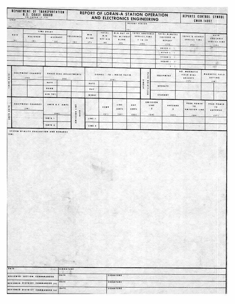
The above form is a later vision (2899-A 2/73) of the original form, form was not part of original manual. C-7-2 SPECIAL LORAN-C REPORTS A. DAILY REPORT. The primary control station for each pair shall report the following information to his next superior in the chain of operational control and to the chain operations control officer. The report shall be made daily, by message using code letters indicated. (1) The average observed envelope time difference reading. (2) The average observed cycle time difference readings. If during the day, the control was shifted, the secondary control station shall submit the above information for the period during which it was in control. The report shall cover the period from 0000Z to 2400Z. The chain operations control officer shall prescribe the time of submission. B. WEEKLY REPORT. All stations shall report submit the following for the week starting 0000z Sunday and ending 2400Z Saturday. A PLOT OF 15 MINUTE TIME DIFFERENCES AVERAGES FOR EACH PAIR IN WHICH THE STATION OPERATES OR WHICH THE STATION MONITORS. Sentence is ineligible C. ADDITIONAL REPORT OR DATA. Officers who exercise command or any type of control over Loran stations may require additional reports or data as they deem necessary. The above requirements are considered minimum for proper supervision of Loran operations. Examples of such additional information which might be required, and, in fact, have been utilized for operational control are: a. Daily reports.
(1) 15-minute averages. (2) Standard deviations of the 15-minute aver- ages. (3) Algebraic totals of ETA’s and CDA’s (4) Changes of equipment. (5) Oscilloscope analysis of amplitude of first 15 cycles of the transmitted pulse taken 2 hours after any transmitter change. b. Weekly reports. (1) Weekly average of 15-minute averages. (2) Weekly standard deviation of 15-minute av- erages. (3) Total unusable time for master. (4) Total unusable time for each slave. (5) Number of master jumps. (6) Total accumulated system unusable time, i.e. unusable time for chain when fix service is considered. C-7-3 LORAN LOGS FORMS CG-2594 AND CG-3912 A. GENERAL. Loran logs are maintained to comprise an acurate accurate history of the operation of a Loran-A pair or a Loran-C pair or chain and of the station at which prepared. The information entered in the logs will normally be that which is observed by the watchstander at his station and form his own scopes. Information received from paired stations may be entered in the remarks column. However, under no circumstances will times of start blink, stop blink, or other comparison of times of entries be obtained by communications from paired stations. During power failures both signal and blink lines for both (all) stations should be left out since the scopes will be blank. Logs shall be prepared in original and one copy. The original shall be filed at the station. The copy shall be forwarded to the officer having operational control of the pair or chain concerned. Loran-C chain operation control officers may direct that an additional copy be made and forwarded to him if he so desires. B. LORAN TRANSMITTING STATION LORAN, CG-2594
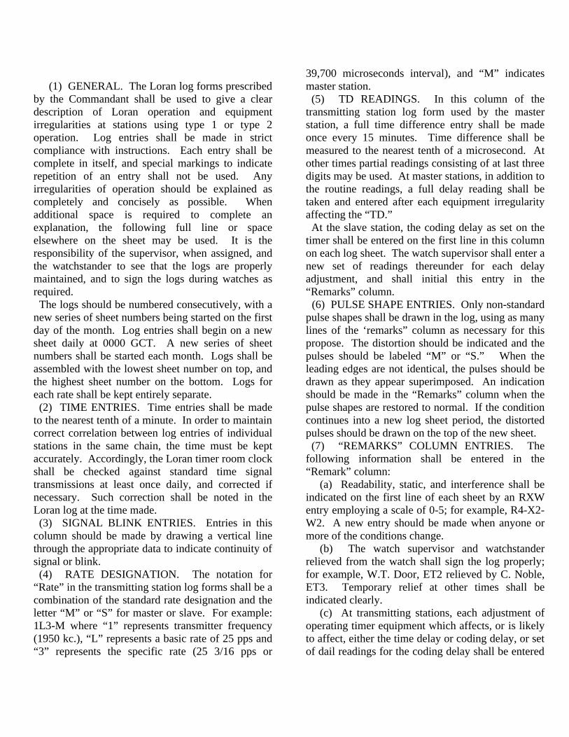
(1) GENERAL. The Loran log forms prescribed by the Commandant shall be used to give a clear description of Loran operation and equipment irregularities at stations using type 1 or type 2 operation. Log entries shall be made in strict compliance with instructions. Each entry shall be complete in itself, and special markings to indicate repetition of an entry shall not be used. Any irregularities of operation should be explained as completely and concisely as possible. When additional space is required to complete an explanation, the following full line or space elsewhere on the sheet may be used. It is the responsibility of the supervisor, when assigned, and the watchstander to see that the logs are properly maintained, and to sign the logs during watches as required. The logs should be numbered consecutively, with a new series of sheet numbers being started on the first day of the month. Log entries shall begin on a new sheet daily at 0000 GCT. A new series of sheet numbers shall be started each month. Logs shall be assembled with the lowest sheet number on top, and the highest sheet number on the bottom. Logs for each rate shall be kept entirely separate. (2) TIME ENTRIES. Time entries shall be made to the nearest tenth of a minute. In order to maintain correct correlation between log entries of individual stations in the same chain, the time must be kept accurately. Accordingly, the Loran timer room clock shall be checked against standard time signal transmissions at least once daily, and corrected if necessary. Such correction shall be noted in the Loran log at the time made. (3) SIGNAL BLINK ENTRIES. Entries in this column should be made by drawing a vertical line through the appropriate data to indicate continuity of signal or blink. (4) RATE DESIGNATION. The notation for “Rate” in the transmitting station log forms shall be a combination of the standard rate designation and the letter “M” or “S” for master or slave. For example: 1L3-M where “1” represents transmitter frequency (1950 kc.), “L” represents a basic rate of 25 pps and “3” represents the specific rate (25 3/16 pps or
39,700 microseconds interval), and “M” indicates master station. (5) TD READINGS. In this column of the transmitting station log form used by the master station, a full time difference entry shall be made once every 15 minutes. Time difference shall be measured to the nearest tenth of a microsecond. At other times partial readings consisting of at last three digits may be used. At master stations, in addition to the routine readings, a full delay reading shall be taken and entered after each equipment irregularity affecting the “TD.” At the slave station, the coding delay as set on the timer shall be entered on the first line in this column on each log sheet. The watch supervisor shall enter a new set of readings thereunder for each delay adjustment, and shall initial this entry in the “Remarks” column. (6) PULSE SHAPE ENTRIES. Only non-standard pulse shapes shall be drawn in the log, using as many lines of the ‘remarks” column as necessary for this propose. The distortion should be indicated and the pulses should be labeled “M” or “S.” When the leading edges are not identical, the pulses should be drawn as they appear superimposed. An indication should be made in the “Remarks” column when the pulse shapes are restored to normal. If the condition continues into a new log sheet period, the distorted pulses should be drawn on the top of the new sheet. (7) “REMARKS” COLUMN ENTRIES. The following information shall be entered in the “Remark” column: (a) Readability, static, and interference shall be indicated on the first line of each sheet by an RXW entry employing a scale of 0-5; for example, R4-X2-W2. A new entry should be made when anyone or more of the conditions change. (b) The watch supervisor and watchstander relieved from the watch shall sign the log properly; for example, W.T. Door, ET2 relieved by C. Noble, ET3. Temporary relief at other times shall be indicated clearly. (c) At transmitting stations, each adjustment of operating timer equipment which affects, or is likely to affect, either the time delay or coding delay, or set of dail readings for the coding delay shall be entered
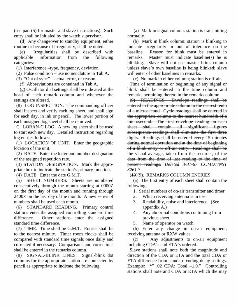
(see par. (5) for master and slave instructions). Such entry shall be initialed by the watch supervisor. (d) Any changeover to standby equipment, either routine or because of irregularity, shall be noted. (e) Irregularities shall be described with applicable information from the following categories: (1) Interference –type, frequency, deviation. (2) Pulse condition – use nomenclature in Tab A. (3) “Out of sync”—actual error, or reason (f) Abbreviations are contained in Tab A. (g) Oscillator dial settings shall be indicated at the head of each remark column and whenever the settings are altered. (8) LOG INSPECTION. The commanding officer shall inspect and verify each log sheet, and shall sign for each day, in ink or pencil. The lower portion of each unsigned log sheet shall be removed. C. LORAN-C LOG. A new log sheet shall be used to start each new day. Detailed instruction regarding log entries follows: (1) LOCATION OF UNIT. Enter the geographic location of the unit. (2) RATE. Enter the letter and number designation of the assigned repetition rate. (3) STATION DESIGNATION. Mark the appro-priate box to indicate the station’s primary function. (4) DATE: Enter the date G.M.T. (5) SHEET NUMBERS: Sheets are numbered consecutively through the month starting at 0000Z on the first day of the month and running through 2400Z on the last day of the month. A new series of numbers shall be used each month. (6) STANDARD READING. Primary control stations enter the assigned controlling standard time difference. Other stations enter the assigned standard time difference. (7) TIME. Time shall be G.M.T. Entries shall be to the nearest minute. Timer room clocks shall be compared with standard time signals once daily and corrected if necessary. Comparisons and corrections shall be entered in the remarks column. (8) SIGNAL-BLINK LINES. Signal-blink dot columns for the appropriate station are connected by pencil as appropriate to indicate the following:
(a) Mark in signal column: station is transmitting normally. (b) Mark in blink column: station is blinking to indicate irregularity or out of tolerance on the baseline. Reason for blink must be entered in remarks. Master must indicate baseline(s) he is blinking. Slave will not use master blink column unless slave’s own baseline is being blinked; slave will enter of other baselines in remarks. (c) No mark in either column; station is off-air. Time of termination or beginning of any signal or blink shall be entered in the time column and remarks pertaining thereto in the remarks column. (9) READINGS. Envelope readings shall be entered in the appropriate column to the nearest tenth of a microsecond. Cycle readings shall be entered in the appropriate column to the nearest hundredth of a microsecond. The first envelope reading on each sheet shall contain all significant figures subsequence readings shall eliminate the first three digits. Readings shall be entered every 15 minutes during normal operation and at the time of beginning of a blink entry or off-air entry. Readings shall be the visual average, taken from the recorder, of the data from the time of last reading to the time of present readings. Deleted 3-31-67 COMDTINST 3261.? (10)(9). REMARKS COLUMN ENTRIES. (a) The first entry of each sheet shall contain the following: 1. Serial numbers of on-air transmitter and timer. 2. Which receiving antenna is in use. 3. Readability, noise and interference. (See appendix A.) 4. Any abnormal conditions continuing from previous sheet. 5. Name of operator on watch. (b) Enter any change in on-air equipment, receiving antenna or RXW values. (c) Any adjustments to on-air equipment including CDA’s and ETA’s ordered. Slave stations shall note both the magnitude and direction of the CDA or ETA and the total CDA or ETA difference from standard coding delay settings. Example: “*” .02 CDA; Total –1.0.” Controlling stations shall note and CDA or ETA which the may
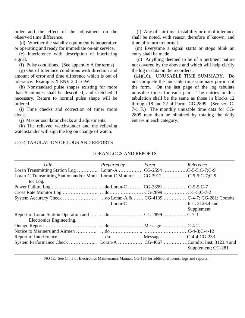
order and the effect of the adjustment on the observed time difference. (d) Whether the standby equipment is inoperative or operating and ready for immediate on-air service. (e) Interference with description of interfering signal. (f) Pulse conditions. (See appendix A for terms) (g) Out of tolerance conditions with direction and amount of error and time difference which is out of tolerance. Example: X ENV 2.0 LOW.” (h) Nonstandard pulse shapes existing for more than 5 minutes shall be described, and sketched if necessary. Return to normal pulse shape will be ordered. (i) Time checks and correction of timer room clock. (j) Master oscillator checks and adjustments. (k) The relieved watchstander and the relieving watchstander will sign the log on change of watch.
(l) Any off-air time, instability or out of tolerance shall be noted, with reason therefore if known, and time of return to normal. (m) Everytime a signal starts or stops blink an entry shall be made. (n) Anything deemed to be of a pertinent nature not covered by the above and which will help clarify the log or data on the recorders.. (11)(10). UNUSABLE TIME SUMMARY. Do not complete the unusable time summary portion of the form. On the last page of the log tabulate unusable times for each pair. The entries in this tabulation shall be the same as those in blocks 12 through 18 and 22 of Form CG-2899. (See sec. C-7-1 F.) The monthly unusable time data for CG-2899 may then be obtained by totaling the daily entries in each category.
C-7-4 TABULATION OF LOGS AND REPORTS
LORAN LOGS AND REPORTS
Title Prepared by-- Form Reference Loran Transmitting Station Log ………….. Loran-A …………… CG-2594 ……………C-5-5;C-7;C-9 Loran-C Transmitting Station and/or Moni-. Loran-C Monitor ….. CG-3912 …………… C-5-5;C-7;C-9 tor Log. Power Failure Log ……………………….. …do Loran-C ……… CG-2899 …………… C-5-5;C-7 Cross Rate Monitor Log …………………. …do………………… CG-2899 ……………C-5-5;C-7-2 System Accuracy Check …………………. …do Loran-A & …… CG-4139 ……………C-4-7; CG-281; Comdts. Loran-C Inst. 3123.4 and Supplement Report of Loran Station Operation and …. …do………………… CG-2899 …………... C-7-1 Electronics Engineering. Outage Reports ………………………….. …do………………… Message …………… C-4-2. Notice to Mariners and Airmen …………. …do ……………….. ………………………C-4-3;C-4-12 Report of Interference …………………… …do ……………….. Message……………..C-4-4;CG-233 System Performance Check ……………... Loran-A …………… CG-4067 ……………Comdts. Inst. 3123.4 and Supplement; CG-281
NOTE: See Ch. 5 of Electronics Maintenance Manual, CG-165 for additional forms, logs and reports.

TAB A
1. Abbreviations authorized for use in Loran Logs. ANS ……… Answer. BLK ……… Blink or blinking. CDA ……… Coding delay adjustment. CY ………… Cycle. ENV ……… Envelope. EQUIP …… Equipment. FDBK ........... Feedback. GMR ……… Ground monitor receiver. LINE I …… Transmission line current. M ………… Master. MINS ……… Minutes MON ……… Monitor ODS ……… Oscillator dial setting. OPR NORM .. Operation normal. PWR ………. Power. R …………… Readability. RCVR ……… Receiver. S …………… Slave AM ………… Area monitor. SEC …………Second. SFT … ………Shift. SPK …………Spike. STP ………… Stopped. SYNC ……… Synchronization. SYNZER ……Synchronizer. TRBL ……… Trouble. USTBL …….. Unstable. W ……………Man made interference. X …………… Atmospheric interference when used with RXW. X …………… X-ray slave when used alone. XMTR ……...Transmitter. Y …………… Yankee slave. Z …………… Zulu slave. Ø …………… Phase. Ø …………… Phase code. us ………….. Microsecond. W ………….. Whiskey slave when used alone. ETA ……….. Envelope timing adjustment.
2. RXW Table. Video signal “R” “X” natural atmospheric scale readability or “W” interfering signals 0 Unreadable…. None. 1 Visible but not usable Weak or infrequent, not troublesome. 2 Occasionally with Moderate, sometimes difficulty. troublesome. 3 Unusable with some Considerable, sometimes difficulty. preventing accurate use. 4 Usable with ease … Strong, usually prevent- ing accurate use. 5 Perfectly usable … Very strong, useful re- caption impossible. 3. Nomenclature used to describe pulse conditions. Blinking ………….. Intermittent nonrhythmic disap- pearance of a pulse or the rhythmic disappearance or shift of a pulse or pulses to denote a Loran irregularity. Breathing ………….. Rhythmic enlarging and contracting of a pulse in size or amplitude (indicate which). Jittery ……………… Entire pulse group unstable. Flapping …………… Unstable trailing edge. Fluttering ………….. Front or top of pulse unsteady (indicate which). Jumping …………… Signals jump out of synchronizat- ion. Drifting ……………. Slow movement or signals in one direction. Searching ………….. Movement of signal back and forth.
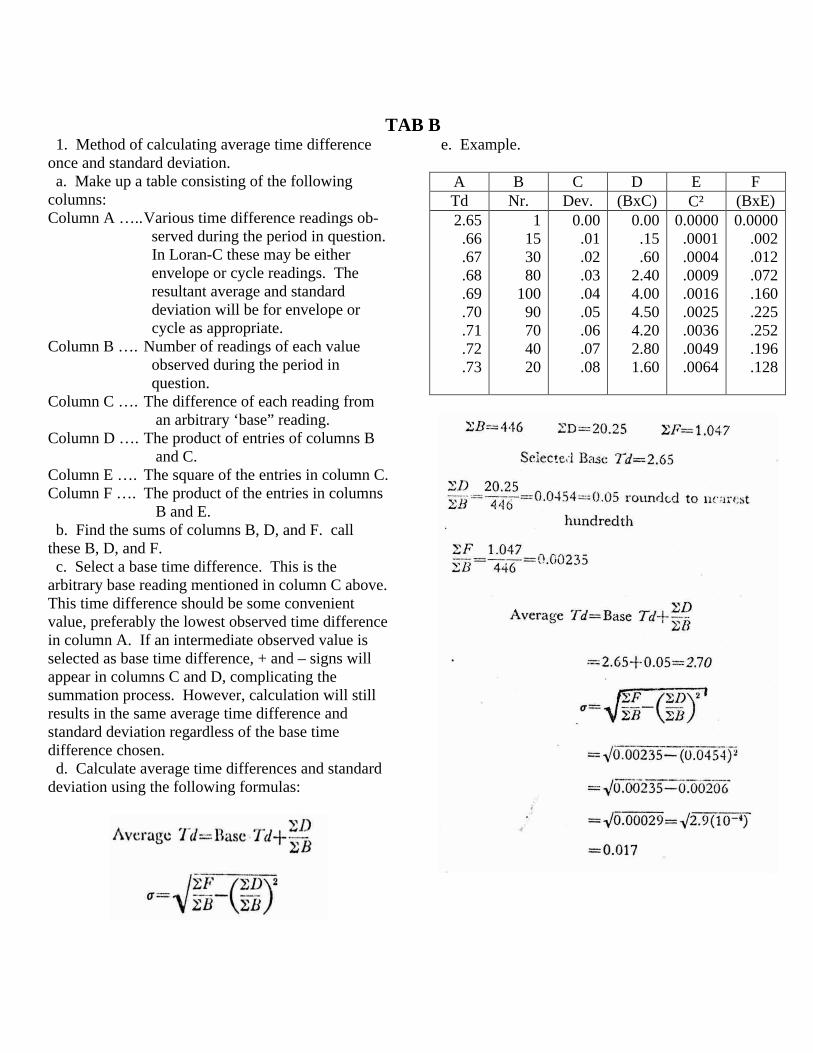
TAB B 1. Method of calculating average time difference once and standard deviation. a. Make up a table consisting of the following columns: Column A ….. Various time difference readings ob- served during the period in question. In Loran-C these may be either envelope or cycle readings. The resultant average and standard deviation will be for envelope or cycle as appropriate. Column B …. Number of readings of each value observed during the period in question. Column C …. The difference of each reading from an arbitrary ‘base” reading. Column D …. The product of entries of columns B and C. Column E …. The square of the entries in column C. Column F …. The product of the entries in columns B and E. b. Find the sums of columns B, D, and F. call these B, D, and F. c. Select a base time difference. This is the arbitrary base reading mentioned in column C above. This time difference should be some convenient value, preferably the lowest observed time difference in column A. If an intermediate observed value is selected as base time difference, + and – signs will appear in columns C and D, complicating the summation process. However, calculation will still results in the same average time difference and standard deviation regardless of the base time difference chosen. d. Calculate average time differences and standard deviation using the following formulas:
e. Example.
A B C D E F Td Nr. Dev. (BxC) C² (BxE) 2.65 .66 .67 .68 .69 .70 .71 .72 .73
1 15 30 80
100 90 70 40 20
0.00 .01 .02 .03 .04 .05 .06 .07 .08
0.00 .15 .60
2.40 4.00 4.50 4.20 2.80 1.60
0.0000 .0001 .0004 .0009 .0016 .0025 .0036 .0049 .0064
0.0000 .002 .012 .072 .160 .225 .252 .196 .128
INDEX TO APPENDIX C Page Accuracy, Factors Determining, Loran …… C-2 Antenna Geometric Factors, Compen- Station, Loran-A ………………………. C-19 Army Requirement, 1940, for Navigation Equipment …………………………….. C-1 Automatic Frequency Control Servo, Operation ……………………………… C-18 Blink, Action Required on Observing …... C-18 Blink Codes, Loran-C …………………… C-23 Blinking Instructions, Loran-A …………. C-18 Blink Instructions, Loran-C …………….. C-22 Blink Procedures, Master, Loran-A …….. C-19 Blink Procedures, Slave, Loran-A ………. C-19 Calculations, Average time Difference and Standard Deviations …………………… C-33 Calibration, Strip Chart Recorder Scales .. C-24 CG-2594, Loran Transmitting Station Log C-28 CG-2899, Report of Loran Station Operation ……………………………… C-25 Chain Commander ………………………. C-12 Chain Configuration, Loran-C System ….. C-6 Chain Operational Control Officer, Duties C-12 Checks, System Accuracy and Perform- ance …………………………………….. C-17 Coding Delay Adjustments, Loran-C: Use of ………………………………….. C-21 Coding Delay, Definition ………………… C-5 Command and Control Organization, Loran System ………………………….. C-9 Commandant (OAN); Assignments Made by ……………………………….. C-16 Commanding Officer, station, Duties …… C-14 Communication failures Loran-C; Procedures for …………………………. C-22 Conditions requiring Blink, Loran-C …….. C-22 Controlling Standard Time Difference, Loran-C ………………………………… C-20 Control Method, Loran-C; Changing of ….. C-22 Control Methods, Loran-C ………………... C-21 Correlated Numbers (Loran-C Time Differences) ……………………………. C-20 Cyclan, Development …………………….. C-2
Page Cycle Match with 2 MC Loran, Develop- ment ……………………………………. C-2 Daily Loran-C Report ……………………. C-27 Envelope Timing Adjustment, Loran C, Use of ………………………………….. C-21 Equipment Operation and Adjustment Loran-C ………………………………… C-24 Errors, Loran System ……………………... C-8 Causes …………………………….. C-8 Effects …………………………….. C-8 Correction …………………………. C-8 Equipment Adjustments, Loran-A ………... C-19 History of Loran …………………………... C-1 Hyperbolic System, basic, Description ……. C-3 Identification, Loran-A Pairs ……………… C-5 Interference, Report of ……………………. C-17 Lights, Aircraft Warning, Transmitting Tower …………………………………… C-18 Log Keeping, Loran-A ……………………. C-19 Log, Loran-C ……………………………… C-29 Logs and Reports, Tabulation …………….. C-31 Logs, Preparation of ………………………. C-28 Loran-A System, Description …………….. C-5 Loran-C Development ……………………. C-1 Loran-C System, General Description ……. C-5 Loran System, Basic, Description ………… C-3 Loran System, Description ……………….. C-3 Loran Systems, Type Descriptions ……….. C-2 Loran Terms, Definitions …………………. C-32 Loran Watchstanders, Duties ……………… C-15 Low frequency Loran, Experiments ………. C-2 Maintenance, Off-Air Time for; Granting … C-17 Maintenance Watch, Loran Station, Duties . C-15 Master Station, Description and Function … C-7 Monitor Station, Description and Function .. C-7 Operating Instruction, General ……………. C-16 Operation Instructions, Loran-A ………….. C-18 Operating Instructions, Loran-C ………….. C-20 Organization, Loran Station ………………. C-8 Phase Coding, Loran-C System …………… C-5 Pulse Repetition Periods, Loran-A Listing .. C-5 Pulse Repetition Periods, Loran-C Listing .. C-7

Page Pulse Shape, Loran-A, Specification ……. C-5 Recording Chart, Loran-A, Marking of …. C-20 Reliability of Loran System, Requirements C-17 Repetition Rate, Definition and Use …….. C-4 Reports, loran-C, Data Sometimes Required C-28 Reports Required ………………………… C-25 Reports Special, for Loran-C ……………. C-27 Report to Higher Authority; Conditions Requiring ……………………………… C-16 Responsibility for Command and Control .. C-12 Resynchronization Following Master jump, Loran-C ………………………………… C-21 Scope Presentation, Loran-A Signals …….. C-5 Second Senior Officer, Loran Station Duties C-14 Senior Technical Officer, Loran Station, Duties …………………………………… C-15
Page Senior Electronics Technician, Loran Station, Duties ………………………….. C-15 Slave Station, Description and Function ….. C-7 Standard Time Difference, Loran-C ………. C-20 Standby equipment, Readiness of …………. C-17 Station Operating Personnel, Duties ……… C-16 Station Organization ……………………… C-13 Station Personnel, Duties …………………. C-14 Strip Chart Recordings ……………………. C-24 Synchronization, correction of, Loran-C …. C-21 Time Difference, Assigned, Loran-C …….. C-20 Timer Adjustments, Loran-A …………….. C-19 Types of Operation, Loran-A …………….. C-18 Wartime Use of Loran (WW II) ………….. C-2 Weekly Loran-C Report ………………….. C-27