Embed Size (px)
Citation preview

INSTALLATION INSTRUCTIONS: LONG TRAVEL KIT
‘07+ FJ CRUISER and ‘05+ TACOMA
ISNTALLATION DIFFICULTY: Advanced
APPROX TIME: 6-8 Hours
REQUIRED TOOLS: 14mm-35mm sockets, wrenches, and ratchet
9/16 and 5/8 12 point sockets
15/16 and 7/8 sockets, wrenches, and ratchet
Channel lock pliers
Welding Equipment and grinding wheel
ALL-PRO OFF-ROAD
AP-305691

INCLUDED COMPONENTS AND HARDWARE:
2 x All-Pro Long Travel Upper Control Arm
- 4 x Washer Per Arm
2 x Upper Control Arm Uniball Bolt
2 x All-Pro Long Travel Lower Control Arm
- 4 x Washer Per Arm - Lower Shock Mount Bolt - Limit Strap Bolt
2 x Lower Control Arm Uniball Bolt
2 x Tie Rod Extension
2 x Extended Brake Line
2 x Spindle Gusset
2 x 12” Limit Strap (and hardware)
EXTRA COMPONENTS:
‘05+ Tacoma or ‘07+ FJ Cruiser Extended Axles (Required for 4x4 Applications)
‘05+ Tacoma or ‘07+ FJ Cruiser Timbren Bump Stops (Optional)
PREFACE – Always practice safe jacking procedures. Failure to do so can result in serious injury or death. If you are unfamiliar with safe jacking procedures and do not feel comfortable, at the very least, read over this guide:
http://www.dummies.com/home-garden/car-repair/how-to-safely-jack-up-your-vehicle/
It is strongly recommended to have a friend help who is experienced in jacking up a vehicle if you are not experienced.

PROCESS:
1.) Account for all components and hardware. Gather tools. 2.) SAFELY jack front of vehicle and place on jack stands – never use the jack to support the
vehicle. 3.) Once vehicle is off the ground, remove the tire and set it aside. 4.) Remove sway bar. It is connected by four bolts through the bottom of the frame and one
in each spindle. 5.) Begin removal of brake caliper. Un-bolt brake line from spindle. Unclip ABS from brake
caliper. DO NOT remove brake line from brake caliper. The brake caliper is attached with two bolts using a 17mm wrench. Remove these and then hang the caliper from the frame.
ABS unplugged
Caliper hung from frame out of the way.
Two bolts to detach the caliper from rotor assembly.

6.) Remove hub covers.
7.) Separate the tie rod end from the spindle using a 19mm wrench.
A tool similar to the one pictured is useful for removing the cover.
Tie Rod
Spindle
Hub with cover removed.

8.) Begin to remove the spindle and hub assembly. To do so, first detach the two bolts from the LCA spindle plate using a 19mm wrench. Put this plate aside as it will need to be modified in later steps.
9.) Remove nut from CV axle attaching it to the hub assembly using a 35mm wrench.
Separate the UCA from the spindle assembly. This can be done using a pickle fork, or by hitting the flat spot on the front of the spindle with a large hammer. Remove hub and spindle assembly entirely.
Two bolts attaching LCA to spindle Two bolts removed from spindle, LCA is no longer attached to spindle.
Flat spot to hit which helps separate UCA from spindle.

10.) Pull CV axle from front differential, tapping it out may be required. NOTE: As soon as the CV is pulled, differential oil will start coming out, have a bucket under the front differential positioned to catch this spillage.
11.) Un-bolt coilover from lower shock mount in LCA. Mark alignment positions on cam bolt and frame to allow for easier alignment after install is complete. Remove cam bolts using 22mm wrench and detach LCA from frame.
12.) Remove coilover by unbolting it from the shock tower using 14mm wrench.
Note how cam bolt is marked.
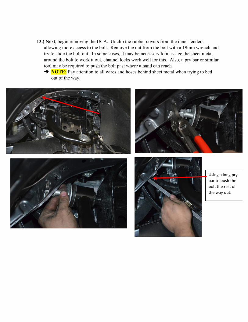
13.) Next, begin removing the UCA. Unclip the rubber covers from the inner fenders allowing more access to the bolt. Remove the nut from the bolt with a 19mm wrench and try to slide the bolt out. In some cases, it may be necessary to massage the sheet metal around the bolt to work it out, channel locks work well for this. Also, a pry bar or similar tool may be required to push the bolt past where a hand can reach. è NOTE: Pay attention to all wires and hoses behind sheet metal when trying to bed
out of the way.
Using a long pry bar to push the bolt the rest of the way out.

14.) Begin installation of new All-Pro Long travel components. Start with the lower control
arms. Hang them from the frame. Put cam bolts through LCA pivots and snug but do not fully tighten. Once snugged, grease zerks. It is best to grease until you see a small amount of grease coming through between the bushing and the washer. After grease is in place, tighten cam bolts down positioned with the markings placed when removing the stock ones. Work the arm up and down after tightening the cam bolts to ensure that grease is worked through the entire pivot. Hang coilover from shock tower.
Grease just starting to squeeze through bushing and washer.

15.) Modify the lower control arm spindle plates. To do so, certain features will need to be ground off. Reference below pictures and grind plates down accordingly.
Stock LCA spindle plate. Want to remove circled.

16.) Remove rotor assembly from spindle in order to weld spindle gusset to stock spindle. Make sure to remove paint from spindle in order to prevent contaminants from entering the weld and making it weaker. Repaint the spindle after gusset is welded and cooled down.
On 4WD models, we recommend taking the complete CV axle, along with the All Pro supplied chromoly axle shafts to a dealer or authorized Toyota service center to have the CV joints removed from the factory shaft and swapped onto the All Pro chromoly shaft. There is no special service tool from Toyota that makes this job easy and most individuals will not have the skill to do themselves. If you are determined to tackle the job yourself, we do not accept responsibility for any damage to the CV joint or injury to yourself should you decide to proceed. We strongly recommend the use of a Toyota Factory Service Manual for this process, but here is a brief outline of the procedure:

17.) Remove inner CV boot clip on the axle. Once boot is off, remove all rings from the inner assembly.
18.) Use a punch to remove the inner CV from the axle.

19.) Remove the boot and CV from the outer CV on the axle shaft. Install the c-clips onto
the new chromoly axle shafts.
20.) Install the new CV boots onto the chromoly axle shafts and install shafts into the original
CV joints. Grease the CV joints and tighten clamps on the CV boots.

21.) Bolt the modified lower control arm spindle plate to the uniball in the lower control arm using a 5/8 12 point for the head and 15/16 wrench for the nut. Bolt the bottom coilover mount to the lower control arm with the supplied bolt. Torque everything to specs listed at the bottom of this guide.
22.) If applicable, begin process of mounting the coilover reservoir. When doing so, ensure there is plenty of clearance between the hose and everything around it, namely, the coilover, the frame, and the upper control arm. Hold reservoir in position, and mark where the weld tabs need to be placed. Prep the frame, removing paint, to ensure quality welds.

23.) Mount upper control arm. Place into position and try to work the bolt through the bushing while placing a black washer on each side of the red bushing. Push through is far as you can by hand. It may be necessary to use a long punch, screwdriver, pry bar, or equivalent to tap bolt in through an access hole found behind the grille of the truck.
Using a large pry bar through the grille, one is able to tap the bolt in through an access hole. The grille can be removed for this process to make it easier.
Access hole behind grille where pry bar goes through.

24.) Once the bolt is all the way through, put the stock nut back on the bolt and snug them up. Then, follow the same procedure as with the LCA to grease the zerks. Grease zerk until grease can just be seen to squeeze through the bushing and the washer, then tighten to spec listed at the bottom of this guide and work arm up and down a few times to ensure that the grease is moved through the entire bushing.
25.) Once upper control arm is installed, reinstall the CV axle with new extended length chromoly shaft. It should reseat into the front differential relatively easy, but tapping it in may be necessary.
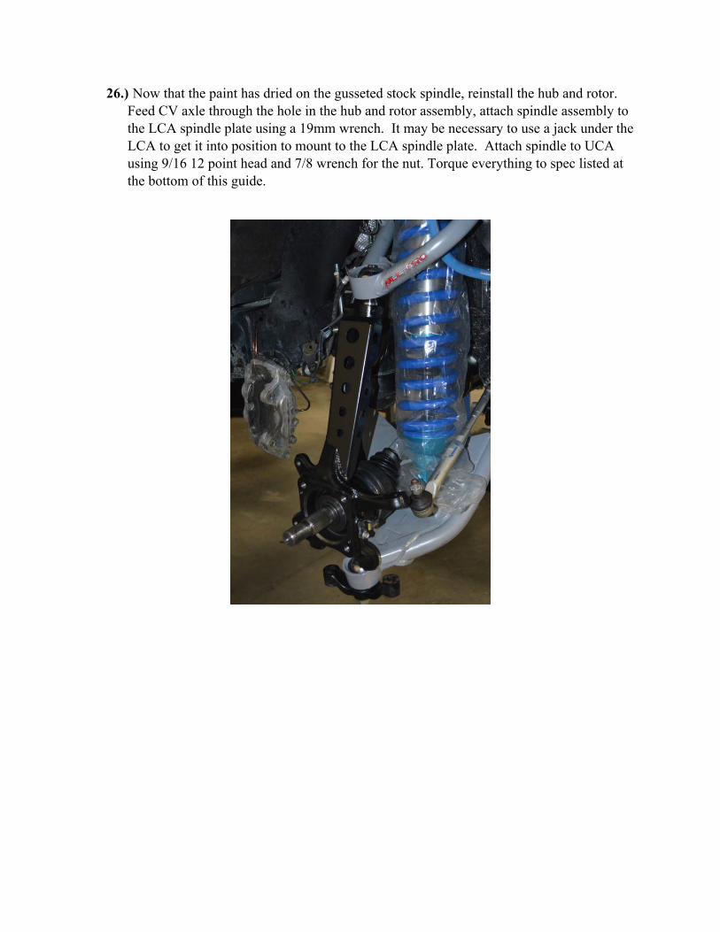
26.) Now that the paint has dried on the gusseted stock spindle, reinstall the hub and rotor. Feed CV axle through the hole in the hub and rotor assembly, attach spindle assembly to the LCA spindle plate using a 19mm wrench. It may be necessary to use a jack under the LCA to get it into position to mount to the LCA spindle plate. Attach spindle to UCA using 9/16 12 point head and 7/8 wrench for the nut. Torque everything to spec listed at the bottom of this guide.

27.) To place frame clevis mount for the limit strap, measure 7” from the back edge of the coilover bucket to the leading top corner of the clevis mount to determine position horizontally.
28.) Measure 7.5” from the bottom edge of the bump stop mount to the same point on the clevis mount that was used for the horizontal indexing to determine location vertically. Angle the mount slightly towards the cab of the vehicle.

29.) Re-install retaining nut on the CV Axle.
30.) Unscrew stock tie-rod end from tie rod using a 21mm wrench for tie rod and 22mm wrench for the nut. Install new extended length tie rod end. Re-install tie-rod end into the spindle. Torque everything to spec.

31.) Reinstall brake caliper assembly and plug in all wires. Re-attach brake line to spindle. Check torque on all bolts. Repeat all above steps on opposite side to complete installation of your new All-Pro 2+ Long Travel Kit. TORQUE SPECS: