Embed Size (px)
Citation preview

3G Long-Term Evolution (LTE) and System Architecture Evolution (SAE)
Background
Evolved Packet System Architecture
LTE Radio Interface
Radio Resource Management
LTE-Advanced
Cellular Communication Systems 2 Andreas Mitschele-Thiel, Jens Mueckenheim Nov. 2015
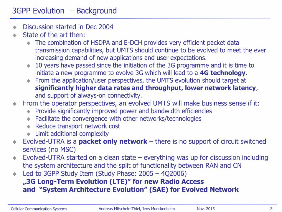
3GPP Evolution – Background
Discussion started in Dec 2004 State of the art then:
The combination of HSDPA and E-DCH provides very efficient packet data transmission capabilities, but UMTS should continue to be evolved to meet the ever increasing demand of new applications and user expectations.
10 years have passed since the initiation of the 3G programme and it is time to initiate a new programme to evolve 3G which will lead to a 4G technology.
From the application/user perspectives, the UMTS evolution should target at significantly higher data rates and throughput, lower network latency, and support of always-on connectivity.
From the operator perspectives, an evolved UMTS will make business sense if it: Provide significantly improved power and bandwidth efficiencies Facilitate the convergence with other networks/technologies Reduce transport network cost Limit additional complexity
Evolved-UTRA is a packet only network – there is no support of circuit switched services (no MSC)
Evolved-UTRA started on a clean state – everything was up for discussion including the system architecture and the split of functionality between RAN and CN
Led to 3GPP Study Item (Study Phase: 2005 – 4Q2006) „3G Long-Term Evolution (LTE)” for new Radio Access and “System Architecture Evolution” (SAE) for Evolved Network
Cellular Communication Systems 3 Andreas Mitschele-Thiel, Jens Mueckenheim Nov. 2015
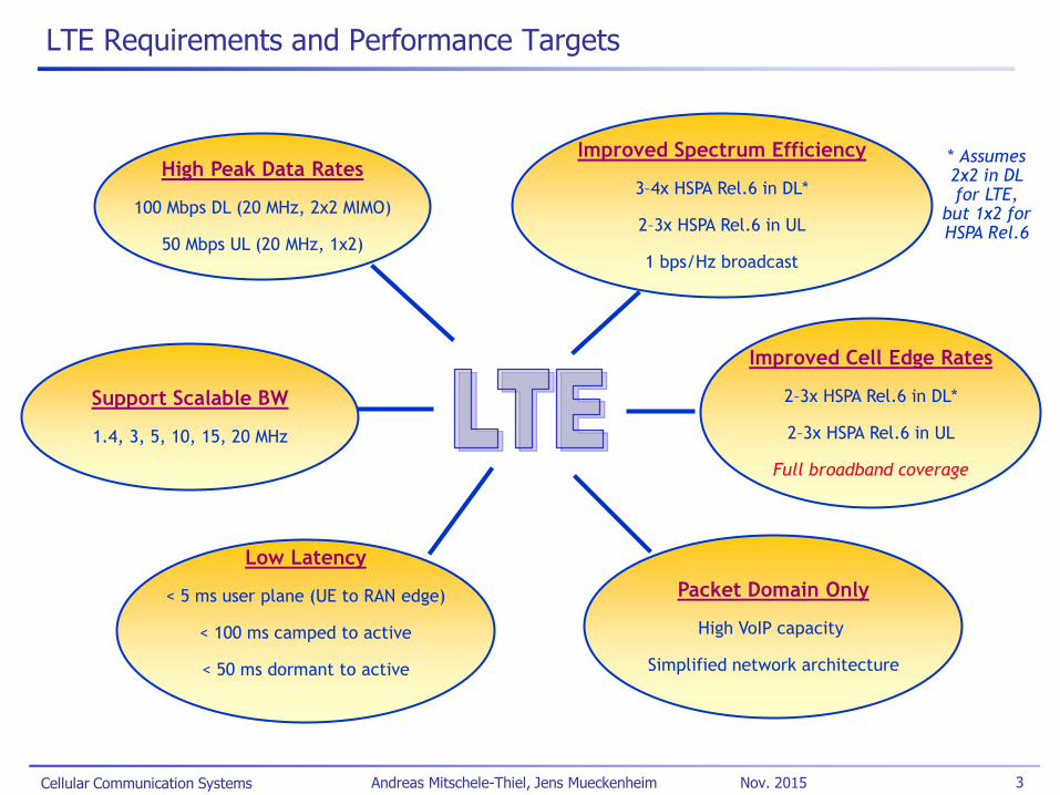
LTE Requirements and Performance Targets
High Peak Data Rates
100 Mbps DL (20 MHz, 2x2 MIMO)
50 Mbps UL (20 MHz, 1x2)
Improved Spectrum Efficiency
3–4x HSPA Rel.6 in DL*
2–3x HSPA Rel.6 in UL
1 bps/Hz broadcast
Improved Cell Edge Rates
2–3x HSPA Rel.6 in DL*
2–3x HSPA Rel.6 in UL
Full broadband coverage
Support Scalable BW
1.4, 3, 5, 10, 15, 20 MHz
Low Latency
< 5 ms user plane (UE to RAN edge)
< 100 ms camped to active
< 50 ms dormant to active
Packet Domain Only
High VoIP capacity
Simplified network architecture
* Assumes 2x2 in DL for LTE,
but 1x2 for HSPA Rel.6
Cellular Communication Systems 4 Andreas Mitschele-Thiel, Jens Mueckenheim Nov. 2015
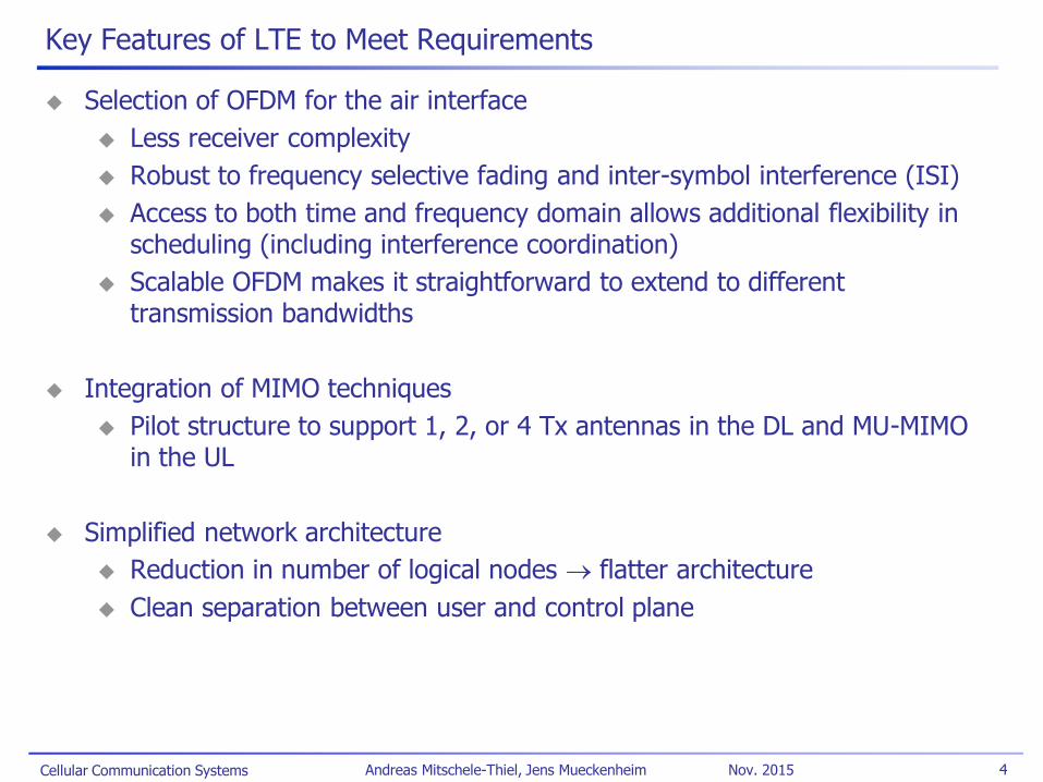
Key Features of LTE to Meet Requirements
Selection of OFDM for the air interface
Less receiver complexity
Robust to frequency selective fading and inter-symbol interference (ISI)
Access to both time and frequency domain allows additional flexibility in scheduling (including interference coordination)
Scalable OFDM makes it straightforward to extend to different transmission bandwidths
Integration of MIMO techniques
Pilot structure to support 1, 2, or 4 Tx antennas in the DL and MU-MIMO in the UL
Simplified network architecture
Reduction in number of logical nodes flatter architecture
Clean separation between user and control plane

Cellular Communication Systems 5 Andreas Mitschele-Thiel, Jens Mueckenheim Nov. 2015
Network Simplification: From 3GPP to 3GPP LTE
3GPP architecture
4 functional entities on the control plane and user plane
3 standardized user plane & control plane interfaces
3GPP LTE architecture
2 functional entities on the user plane: eNodeB and S-GW
SGSN control plane functions S-GW & MME
Less interfaces, some functions disappeared
4 layers into 2 layers
Evolved GGSN integrated S-GW
Moved SGSN functionalities to S-GW.
RNC evolutions to RRM on a IP distributed network for enhancing mobility management.
Part of RNC mobility function moved to S-GW & eNodeB
GGSN
SGSN
RNC
NodeB
ASGW
eNodeB
MMF
GGSN
SGSN
RNC
NodeB
Control plane User plane
ASGW
eNodeB
MMF
S-GW
eNodeB
MME
Control plane User plane
S-GW: Serving Gateway MME: Mobility Management Entity
eNodeB: Evolved NodeB
Cellular Communication Systems 6 Andreas Mitschele-Thiel, Jens Mueckenheim Nov. 2015
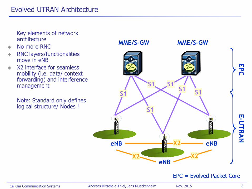
Evolved UTRAN Architecture
eNB
eNB
eNB
MME/S-GW MME/S-GW
X2
EPC
E-U
TR
AN
S1
S1
S1 S1
S1
S1
X2
X2
EPC = Evolved Packet Core
Key elements of network architecture
No more RNC
RNC layers/functionalities move in eNB
X2 interface for seamless mobility (i.e. data/ context forwarding) and interference management
Note: Standard only defines logical structure/ Nodes !
Cellular Communication Systems 7 Andreas Mitschele-Thiel, Jens Mueckenheim Nov. 2015
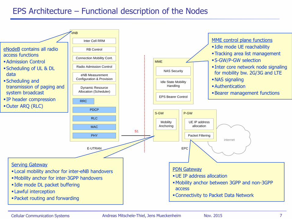
EPS Architecture – Functional description of the Nodes
internet
eNB
RB Control
Connection Mobility Cont.
eNB Measurement
Configuration & Provision
Dynamic Resource
Allocation (Scheduler)
PDCP
PHY
MME
S-GW
S1
MAC
Inter Cell RRM
Radio Admission Control
RLC
E-UTRAN EPC
RRC
Mobility
Anchoring
EPS Bearer Control
Idle State Mobility
Handling
NAS Security
P-GW
UE IP address
allocation
Packet Filtering
eNodeB contains all radio access functions
Admission Control
Scheduling of UL & DL data
Scheduling and transmission of paging and system broadcast
IP header compression
Outer ARQ (RLC)
Serving Gateway
Local mobility anchor for inter-eNB handovers
Mobility anchor for inter-3GPP handovers
Idle mode DL packet buffering
Lawful interception
Packet routing and forwarding
PDN Gateway
UE IP address allocation
Mobility anchor between 3GPP and non-3GPP access
Connectivity to Packet Data Network
MME control plane functions
Idle mode UE reachability
Tracking area list management
S-GW/P-GW selection
Inter core network node signaling for mobility bw. 2G/3G and LTE
NAS signaling
Authentication
Bearer management functions

Cellular Communication Systems 8 Andreas Mitschele-Thiel, Jens Mueckenheim Nov. 2015
EPS Architecture – Control Plane Layout over S1
eNB
PHY
UE
PHY
MAC
RLC
MAC
MME
RLC
NAS NAS
RRC RRC
PDCP PDCP
UE eNodeB MME
RRC sub-layer performs:
Broadcasting
Paging
Connection Management
Radio bearer control
Mobility functions
UE measurement reporting & control
PDCP sub-layer performs:
Integrity protection & ciphering
NAS sub-layer performs:
Authentication
Security control
Idle mode mobility handling
Idle mode paging origination
Cellular Communication Systems 9 Andreas Mitschele-Thiel, Jens Mueckenheim Nov. 2015
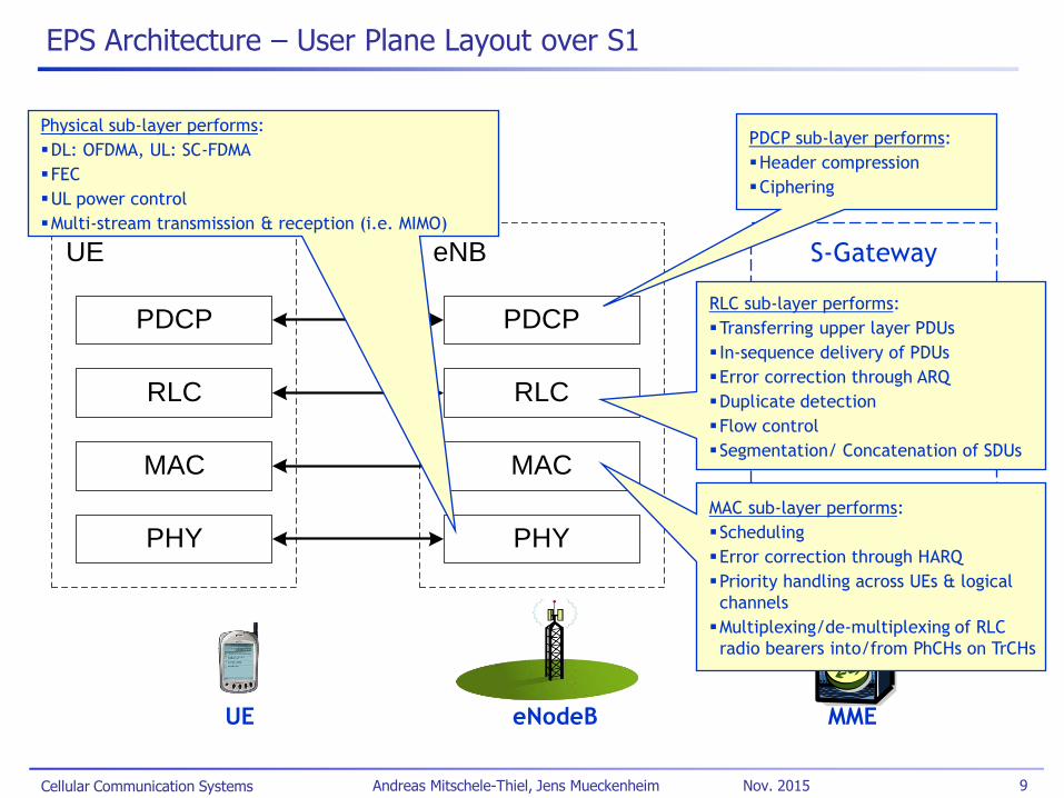
EPS Architecture – User Plane Layout over S1
UE eNodeB MME
eNB
PHY
UE
PHY
MAC
RLC
MAC
PDCPPDCP
RLC
S-Gateway
RLC sub-layer performs:
Transferring upper layer PDUs
In-sequence delivery of PDUs
Error correction through ARQ
Duplicate detection
Flow control
Segmentation/ Concatenation of SDUs
PDCP sub-layer performs:
Header compression
Ciphering
MAC sub-layer performs:
Scheduling
Error correction through HARQ
Priority handling across UEs & logical
channels
Multiplexing/de-multiplexing of RLC
radio bearers into/from PhCHs on TrCHs
Physical sub-layer performs:
DL: OFDMA, UL: SC-FDMA
FEC
UL power control
Multi-stream transmission & reception (i.e. MIMO)

Cellular Communication Systems 10 Andreas Mitschele-Thiel, Jens Mueckenheim Nov. 2015
EPS Architecture – Interworking for 3GPP and non-3GPP Access
Home Subscriber Server (HSS) is the subscription data repository for permanent user data (subscriber profile).
Policy Charging Rules Function (PCRF) provides the policy and charging control (PCC) rules for controlling the QoS as well as charging the user, accordingly.
S3 interface connects MME directly to SGSN for signaling to support mobility across LTE and UTRAN/GERAN; S4 allows direction of user plane between LTE and GERAN/ UTRAN (uses GTP)
GERAN
UTRAN
E-UTRAN
SGSN
MME
non-3GPP Access
Serving GW PDN GW
S1-U
S1-MME S11
S3
S4
S5
Internet
EPS Core
S12
SGi
HSS
S6a
S10
PCRF
Gx
Gxc

Cellular Communication Systems 11 Andreas Mitschele-Thiel, Jens Mueckenheim Nov. 2015
LTE Key Radio Features (Release 8)
Multiple access scheme
DL: OFDMA with CP
UL: Single Carrier FDMA (SC-FDMA) with CP
Adaptive modulation and coding
DL modulations: QPSK, 16QAM, and 64QAM
UL modulations: QPSK, 16QAM, and 64QAM (optional for UE)
Rel.6 Turbo code: Coding rate of 1/3, two 8-state constituent encoders, and a contention-free internal interleaver.
ARQ within RLC sublayer and Hybrid ARQ within MAC sublayer.
Advanced MIMO spatial multiplexing techniques
(2 or 4)x(2 or 4) downlink and 1x(2 or 4) uplink supported.
Multi-layer transmission with up to four streams.
Multi-user MIMO also supported.
Implicit support for interference coordination
Support for both FDD and TDD
Cellular Communication Systems 12 Andreas Mitschele-Thiel, Jens Mueckenheim Nov. 2015
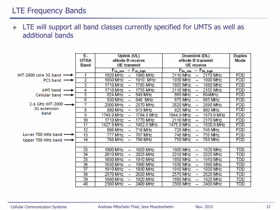
LTE Frequency Bands
LTE will support all band classes currently specified for UMTS as well as additional bands
Cellular Communication Systems 13 Andreas Mitschele-Thiel, Jens Mueckenheim Nov. 2015
OFDM Basics – Overlapping Orthogonal
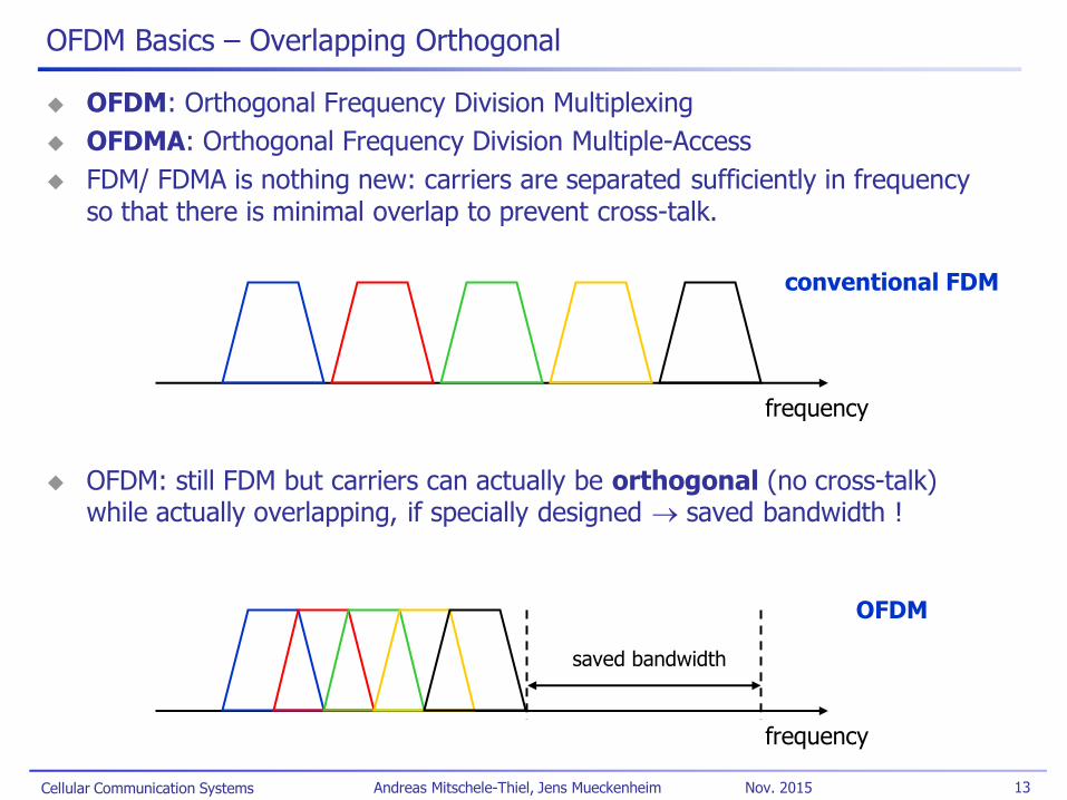
OFDM: Orthogonal Frequency Division Multiplexing
OFDMA: Orthogonal Frequency Division Multiple-Access
FDM/ FDMA is nothing new: carriers are separated sufficiently in frequency so that there is minimal overlap to prevent cross-talk.
OFDM: still FDM but carriers can actually be orthogonal (no cross-talk) while actually overlapping, if specially designed saved bandwidth !
conventional FDM
frequency
OFDM
frequency
saved bandwidth

Cellular Communication Systems 14 Andreas Mitschele-Thiel, Jens Mueckenheim Nov. 2015
OFDM Basics – Waveforms
Frequency domain: overlapping sinc functions
Referred to as subcarriers
Typically quite narrow, e.g. 15 kHz
Time domain: simple gated sinusoid functions
For orthogonality: each symbol has an integer number of cycles over the symbol time
fundamental frequency f0 = 1/T
Other sinusoids with fk = k • f0
Df = 1/T
freq.
time
T = symbol time
0 1 2 3 4 5 6 -0.2
0
0.2
0.4
0.6
0.8
1
0 0.2 0.4 0.6 0.8 1 -1
-0.5
0
0.5
1
Cellular Communication Systems 15 Andreas Mitschele-Thiel, Jens Mueckenheim Nov. 2015
OFDM Basics – The Full OFDM Transceiver
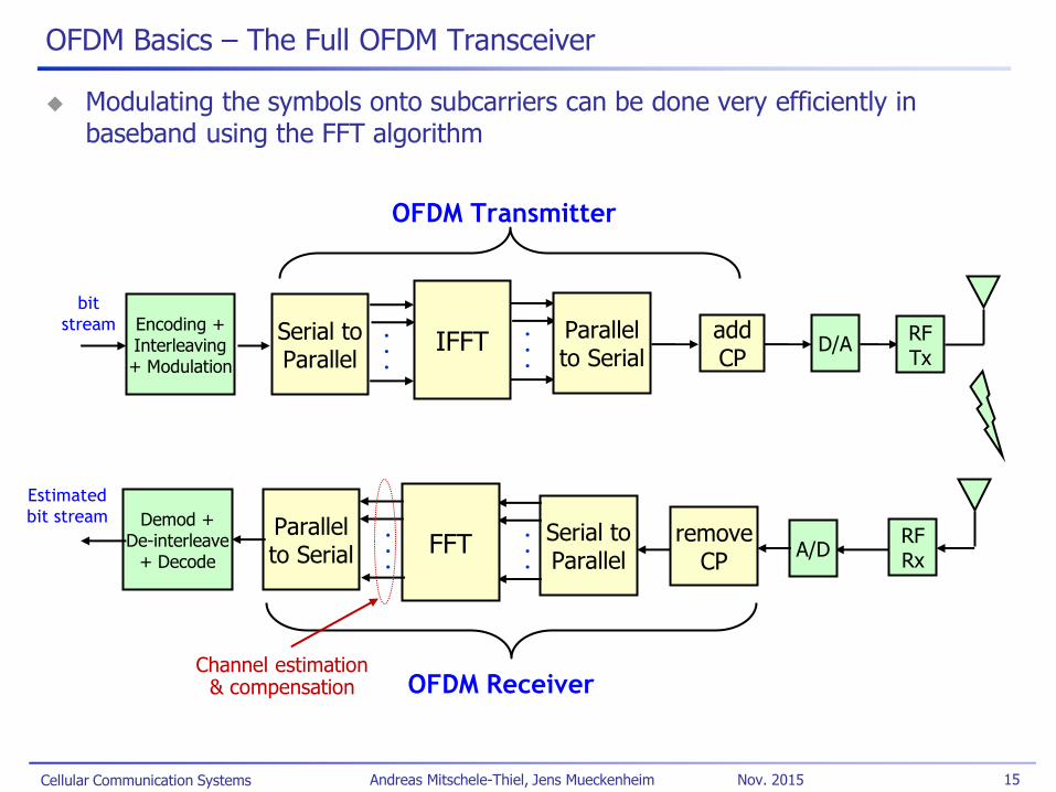
Modulating the symbols onto subcarriers can be done very efficiently in baseband using the FFT algorithm
Serial to Parallel
. . .
IFFT
bit
stream . . .
Parallel to Serial
D/A
A/D Serial to Parallel
. . . FFT
. . .
OFDM Transmitter
OFDM Receiver
Parallel to Serial
add CP
RF Tx
RF Rx
remove CP
Encoding + Interleaving + Modulation
Demod + De-interleave
+ Decode
Estimated
bit stream
Channel estimation & compensation
Cellular Communication Systems 16 Andreas Mitschele-Thiel, Jens Mueckenheim Nov. 2015
OFDM Basics – Cyclic Prefix
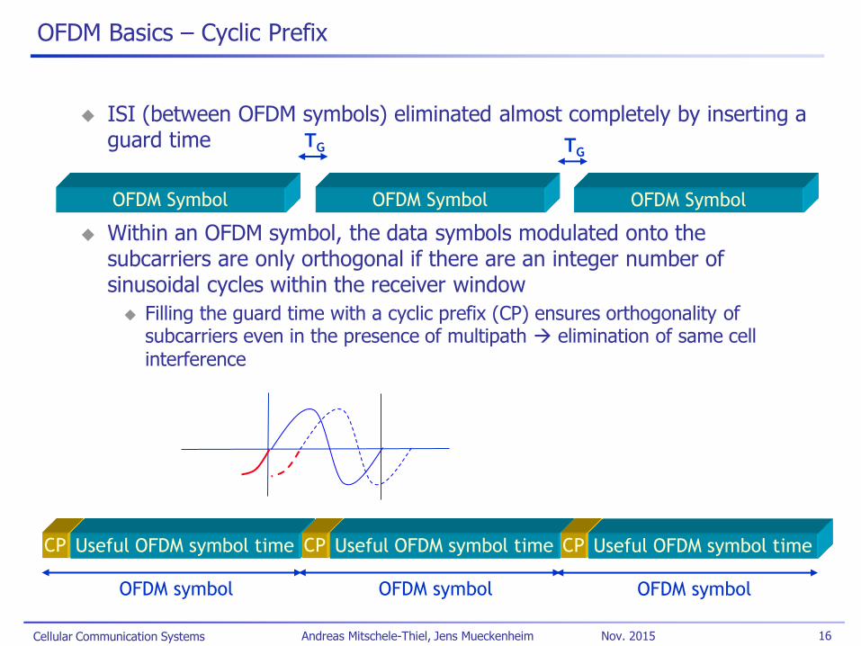
ISI (between OFDM symbols) eliminated almost completely by inserting a guard time
Within an OFDM symbol, the data symbols modulated onto the subcarriers are only orthogonal if there are an integer number of sinusoidal cycles within the receiver window
Filling the guard time with a cyclic prefix (CP) ensures orthogonality of subcarriers even in the presence of multipath elimination of same cell interference
CP Useful OFDM symbol time
OFDM symbol
CP Useful OFDM symbol time
OFDM symbol
CP Useful OFDM symbol time
OFDM symbol
OFDM Symbol OFDM Symbol OFDM Symbol
TG TG
Cellular Communication Systems 17 Andreas Mitschele-Thiel, Jens Mueckenheim Nov. 2015
Comparison with CDMA – Principle
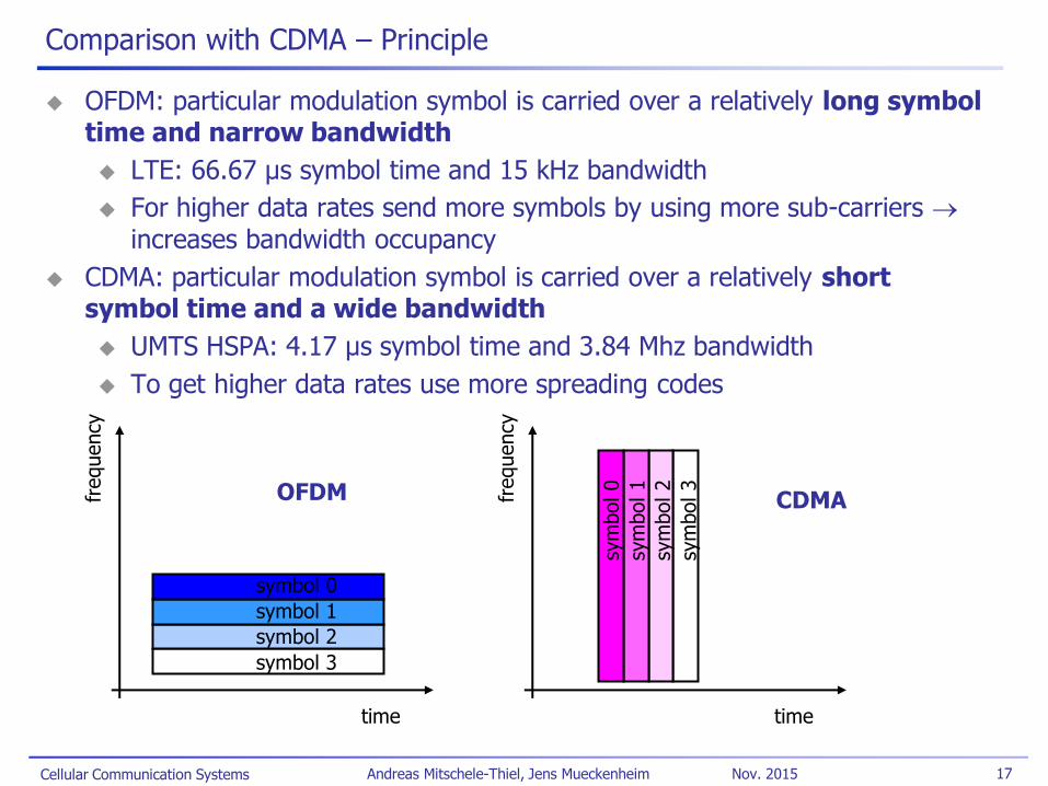
OFDM: particular modulation symbol is carried over a relatively long symbol time and narrow bandwidth
LTE: 66.67 µs symbol time and 15 kHz bandwidth
For higher data rates send more symbols by using more sub-carriers increases bandwidth occupancy
CDMA: particular modulation symbol is carried over a relatively short symbol time and a wide bandwidth
UMTS HSPA: 4.17 µs symbol time and 3.84 Mhz bandwidth
To get higher data rates use more spreading codes
time
frequency
symbol 0
symbol 1
symbol 2
symbol 3
time
frequency
sym
bol 0
sym
bol 1
sym
bol 2
sym
bol 3
OFDM CDMA
Cellular Communication Systems 18 Andreas Mitschele-Thiel, Jens Mueckenheim Nov. 2015
Comparison with CDMA – Time Domain Perspective
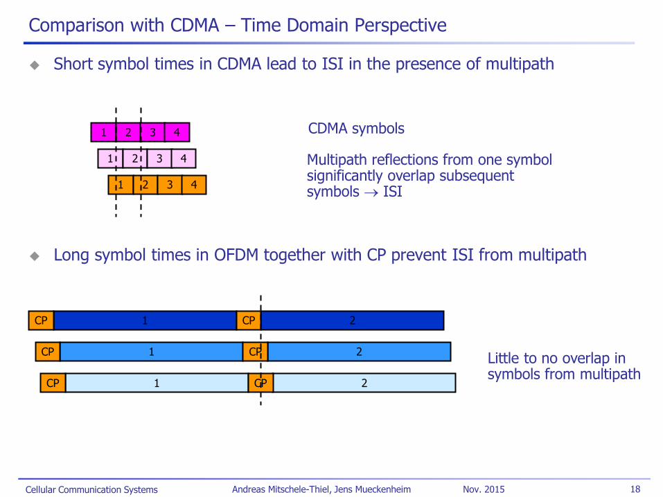
Short symbol times in CDMA lead to ISI in the presence of multipath
Long symbol times in OFDM together with CP prevent ISI from multipath
1 2 3 4
1 2 3 4
1 2 3 4
CDMA symbols
Multipath reflections from one symbol significantly overlap subsequent symbols ISI
1 2 CP CP
1 2 CP CP
1 2 CP CP
Little to no overlap in symbols from multipath
Cellular Communication Systems 19 Andreas Mitschele-Thiel, Jens Mueckenheim Nov. 2015
Comparison with CDMA – Frequency Domain Perspective
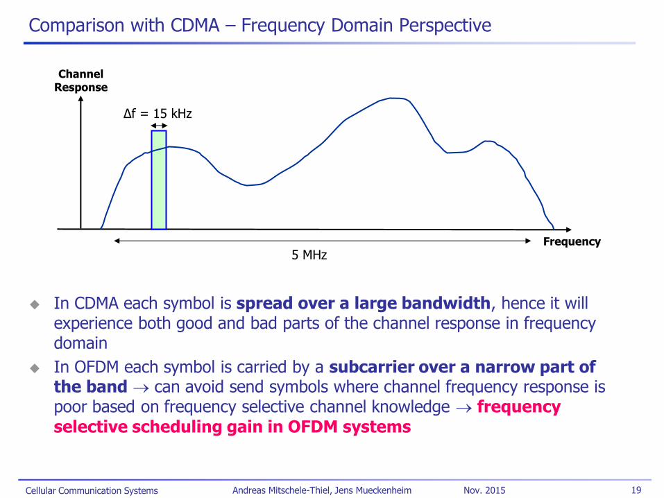
In CDMA each symbol is spread over a large bandwidth, hence it will experience both good and bad parts of the channel response in frequency domain
In OFDM each symbol is carried by a subcarrier over a narrow part of the band can avoid send symbols where channel frequency response is poor based on frequency selective channel knowledge frequency selective scheduling gain in OFDM systems
Frequency
Channel Response
Δf = 15 kHz
5 MHz
Cellular Communication Systems 20 Andreas Mitschele-Thiel, Jens Mueckenheim Nov. 2015
OFDM Basics – Choosing the Symbol Time for LTE
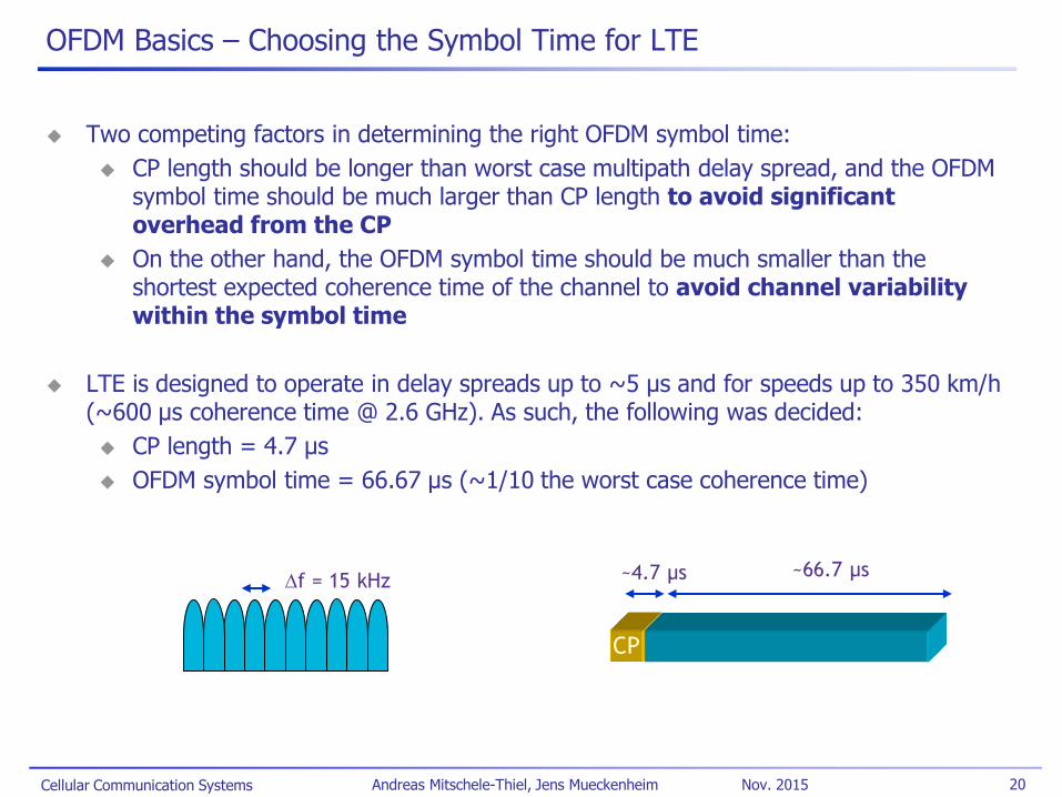
Two competing factors in determining the right OFDM symbol time:
CP length should be longer than worst case multipath delay spread, and the OFDM symbol time should be much larger than CP length to avoid significant overhead from the CP
On the other hand, the OFDM symbol time should be much smaller than the shortest expected coherence time of the channel to avoid channel variability within the symbol time
LTE is designed to operate in delay spreads up to ~5 μs and for speeds up to 350 km/h (~600 µs coherence time @ 2.6 GHz). As such, the following was decided:
CP length = 4.7 μs
OFDM symbol time = 66.67 μs (~1/10 the worst case coherence time)
Df = 15 kHz
CP
~4.7 µs
~66.7 µs

Cellular Communication Systems 21 Andreas Mitschele-Thiel, Jens Mueckenheim Nov. 2015
Scalable OFDM for Different Operating Bandwidths
With Scalable OFDM, the subcarrier spacing stays fixed at 15 kHz (hence symbol time is fixed to 66.67 µs) regardless of the operating bandwidth (1.4 MHz, 3 MHz, 5 MHz, 10 MHz, 15 MHz, 20 MHz)
The total number of subcarriers is varied in order to operate in different bandwidths
This is done by specifying different FFT sizes (i.e. 512 point FFT for 5 MHz, 2048 point FFT for 20 MHz)
Influence of delay spread, Doppler due to user mobility, timing accuracy, etc. remain the same as the system bandwidth is changed robust design
common channels
10 MHz bandwidth
20 MHz bandwidth
5 MHz bandwidth
1.4 MHz bandwidth
3 MHz bandwidth
centre frequency

Cellular Communication Systems 22 Andreas Mitschele-Thiel, Jens Mueckenheim Nov. 2015
LTE Downlink Frame Format
Subframe length is 1 ms
consists of two 0.5 ms slots
7 OFDM symbols per 0.5 ms slot 14 OFDM symbols per 1ms subframe
In UL center SC-FDMA symbol used for the data demodulation reference signal (DM-RS)
slot = 0.5 ms slot = 0.5 ms
subframe = 1.0 ms
OFDM symbol
Radio frame = 10 ms
Cellular Communication Systems 23 Andreas Mitschele-Thiel, Jens Mueckenheim Nov. 2015
Spatial Multiplexing
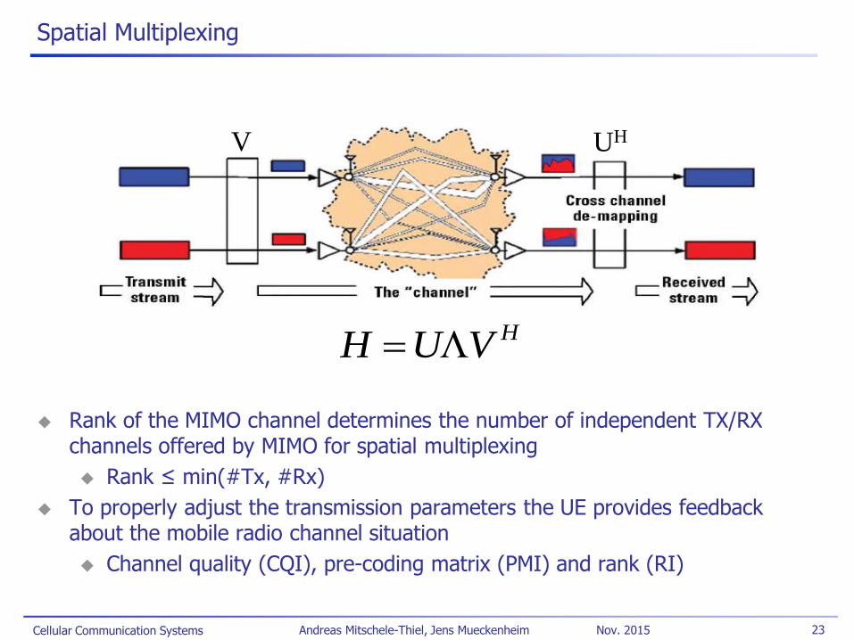
Rank of the MIMO channel determines the number of independent TX/RX channels offered by MIMO for spatial multiplexing
Rank ≤ min(#Tx, #Rx)
To properly adjust the transmission parameters the UE provides feedback about the mobile radio channel situation
Channel quality (CQI), pre-coding matrix (PMI) and rank (RI)
HVUH
UH V

Cellular Communication Systems 24 Andreas Mitschele-Thiel, Jens Mueckenheim Nov. 2015
Multiple Antenna Techniques Supported in LTE
SU-MIMO
Multiple data streams sent to the same user (max. 2 codewords)
Significant throughput gains for UEs in high SINR conditions
MU-MIMO or Beamforming
Different data streams sent to different users using the same time-frequency resources
Improves throughput even in low SINR conditions (cell-edge)
Works even for single antenna mobiles
Transmit diversity (TxDiv) Improves reliability on a single data stream Fall back scheme if channel conditions do
not allow MIMO Useful to improve reliability on common
control channels
Cellular Communication Systems 25 Andreas Mitschele-Thiel, Jens Mueckenheim Nov. 2015
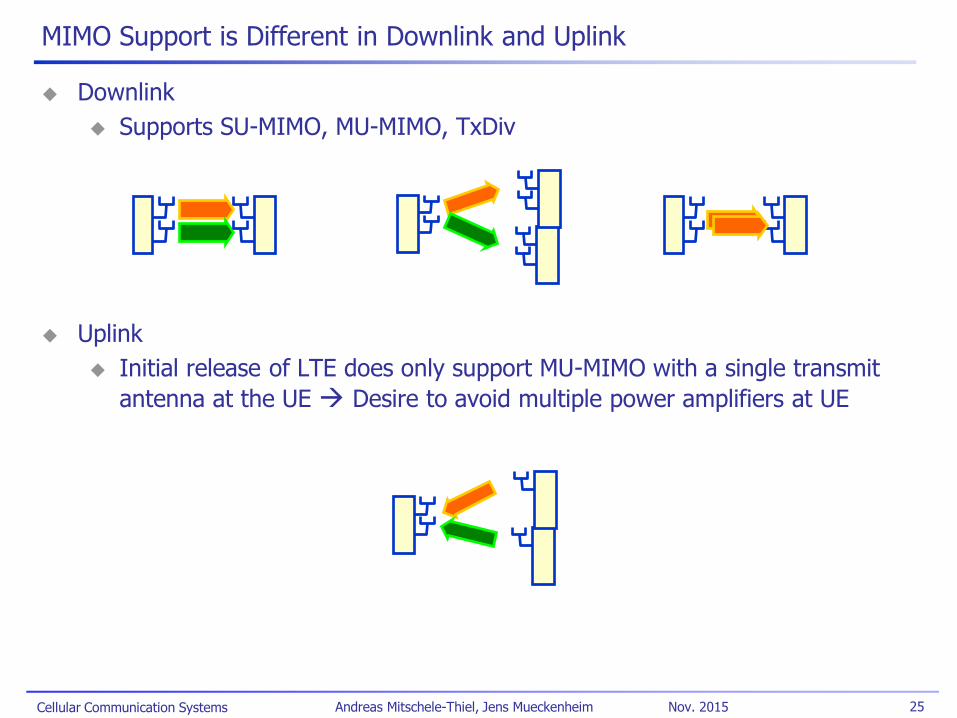
MIMO Support is Different in Downlink and Uplink
Downlink
Supports SU-MIMO, MU-MIMO, TxDiv
Uplink
Initial release of LTE does only support MU-MIMO with a single transmit
antenna at the UE Desire to avoid multiple power amplifiers at UE
Cellular Communication Systems 26 Andreas Mitschele-Thiel, Jens Mueckenheim Nov. 2015
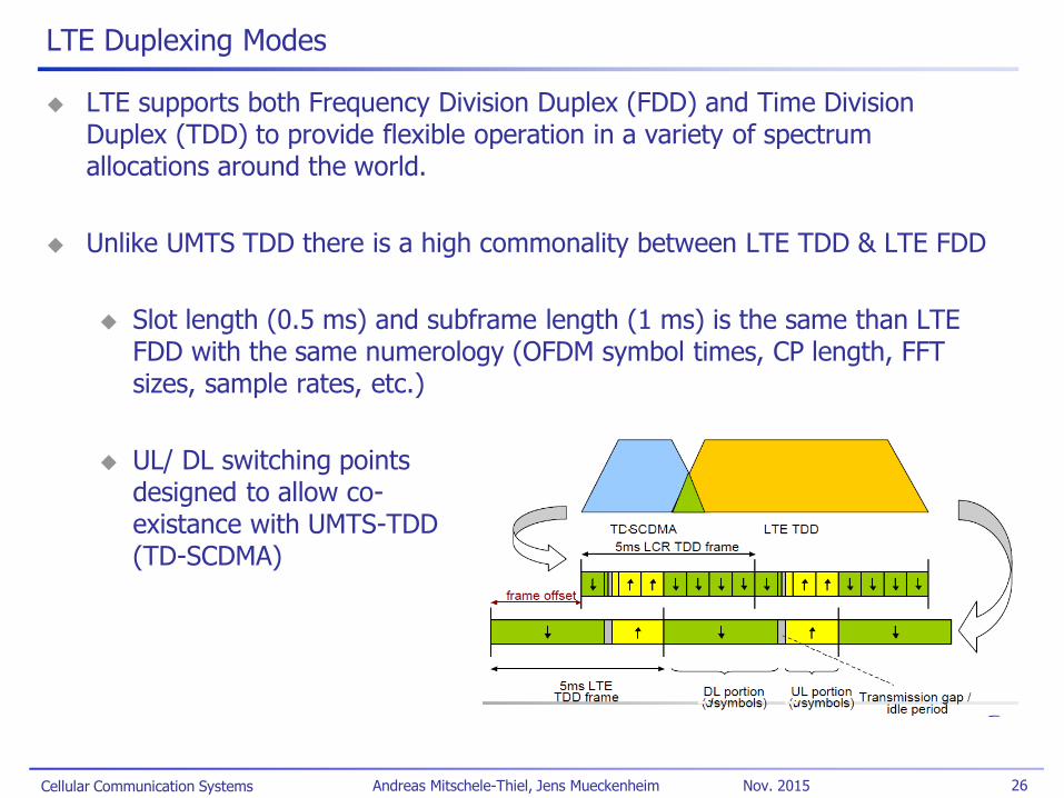
LTE Duplexing Modes
LTE supports both Frequency Division Duplex (FDD) and Time Division Duplex (TDD) to provide flexible operation in a variety of spectrum allocations around the world.
Unlike UMTS TDD there is a high commonality between LTE TDD & LTE FDD
Slot length (0.5 ms) and subframe length (1 ms) is the same than LTE FDD with the same numerology (OFDM symbol times, CP length, FFT sizes, sample rates, etc.)
UL/ DL switching points designed to allow co- existance with UMTS-TDD (TD-SCDMA)
Cellular Communication Systems 27 Andreas Mitschele-Thiel, Jens Mueckenheim Nov. 2015
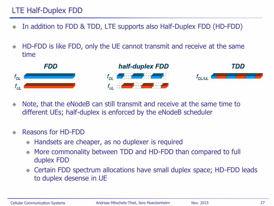
LTE Half-Duplex FDD
In addition to FDD & TDD, LTE supports also Half-Duplex FDD (HD-FDD)
HD-FDD is like FDD, only the UE cannot transmit and receive at the same time
Note, that the eNodeB can still transmit and receive at the same time to different UEs; half-duplex is enforced by the eNodeB scheduler
Reasons for HD-FDD
Handsets are cheaper, as no duplexer is required
More commonality between TDD and HD-FDD than compared to full duplex FDD
Certain FDD spectrum allocations have small duplex space; HD-FDD leads to duplex desense in UE
Cellular Communication Systems 28 Andreas Mitschele-Thiel, Jens Mueckenheim Nov. 2015
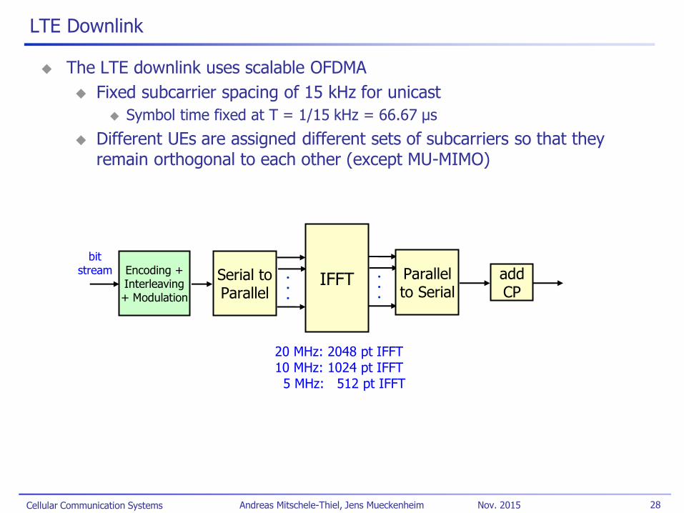
LTE Downlink
The LTE downlink uses scalable OFDMA
Fixed subcarrier spacing of 15 kHz for unicast
Symbol time fixed at T = 1/15 kHz = 66.67 µs
Different UEs are assigned different sets of subcarriers so that they remain orthogonal to each other (except MU-MIMO)
Serial to Parallel
. . .
IFFT
bit stream . . .
Parallel to Serial
add CP
Encoding + Interleaving + Modulation
20 MHz: 2048 pt IFFT
10 MHz: 1024 pt IFFT 5 MHz: 512 pt IFFT
Cellular Communication Systems 29 Andreas Mitschele-Thiel, Jens Mueckenheim Nov. 2015
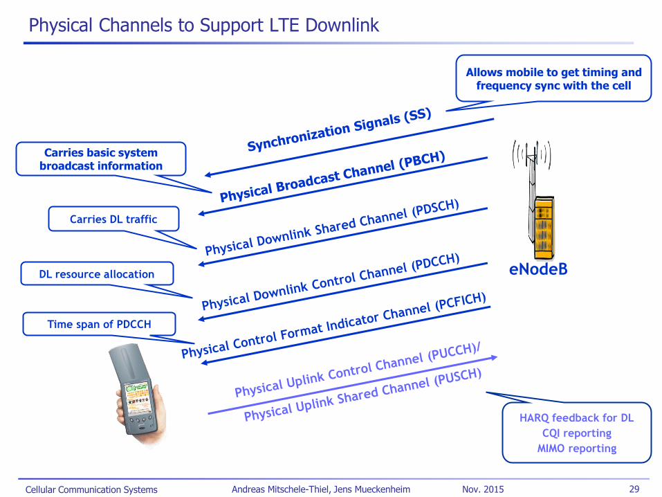
Physical Channels to Support LTE Downlink
eNodeB
Carries DL traffic
DL resource allocation
HARQ feedback for DL
CQI reporting
MIMO reporting
Time span of PDCCH
Carries basic system broadcast information
Allows mobile to get timing and frequency sync with the cell
Cellular Communication Systems 30 Andreas Mitschele-Thiel, Jens Mueckenheim Nov. 2015
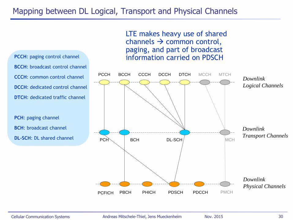
Mapping between DL Logical, Transport and Physical Channels
LTE makes heavy use of shared channels common control, paging, and part of broadcast information carried on PDSCH PCCH: paging control channel
BCCH: broadcast control channel
CCCH: common control channel
DCCH: dedicated control channel
DTCH: dedicated traffic channel
PCH: paging channel
BCH: broadcast channel
DL-SCH: DL shared channel
BCCHPCCH CCCH DCCH DTCH MCCH MTCH
BCHPCH DL-SCH MCH
Downlink
Logical Channels
Downlink
Transport Channels
Downlink
Physical ChannelsPDSCH PDCCHPBCH PHICHPCFICH PMCH
Cellular Communication Systems 31 Andreas Mitschele-Thiel, Jens Mueckenheim Nov. 2015
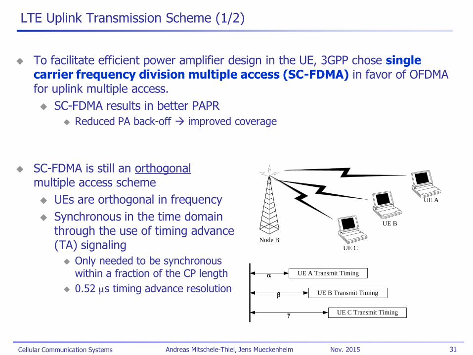
LTE Uplink Transmission Scheme (1/2)
To facilitate efficient power amplifier design in the UE, 3GPP chose single carrier frequency division multiple access (SC-FDMA) in favor of OFDMA for uplink multiple access.
SC-FDMA results in better PAPR
Reduced PA back-off improved coverage
SC-FDMA is still an orthogonal multiple access scheme
UEs are orthogonal in frequency
Synchronous in the time domain through the use of timing advance (TA) signaling
Only needed to be synchronous within a fraction of the CP length
0.52 ms timing advance resolution
Node B
UE C
UE B
UE A
UE A Transmit Timing
UE B Transmit Timing
UE C Transmit Timing
a
b
g

Cellular Communication Systems 32 Andreas Mitschele-Thiel, Jens Mueckenheim Nov. 2015
LTE Uplink Transmission Scheme (2/2)
SC-FDMA implemented using an OFDMA front-end and a DFT pre-coder, this is referred to as either DFT-pre-coded OFDMA or DFT-spread OFDMA (DFT-SOFDMA)
Advantage is that numerology (subcarrier spacing, symbol times, FFT sizes, etc.) can be shared between uplink and downlink
Can still allocate variable bandwidth in units of 12 sub-carriers
Each modulation symbol sees a wider bandwidth
+1 -1
-1 +
1 -1
-1 -1
+1 +
1 +
1 -1
DFT pre-coding
Serial to Parallel IFFT
bit
stream . . .
Parallel to Serial
add CP
Encoding + Interleaving + Modulation
. . DFT . . .
. .
Subcarrier mapping
Cellular Communication Systems 33 Andreas Mitschele-Thiel, Jens Mueckenheim Nov. 2015
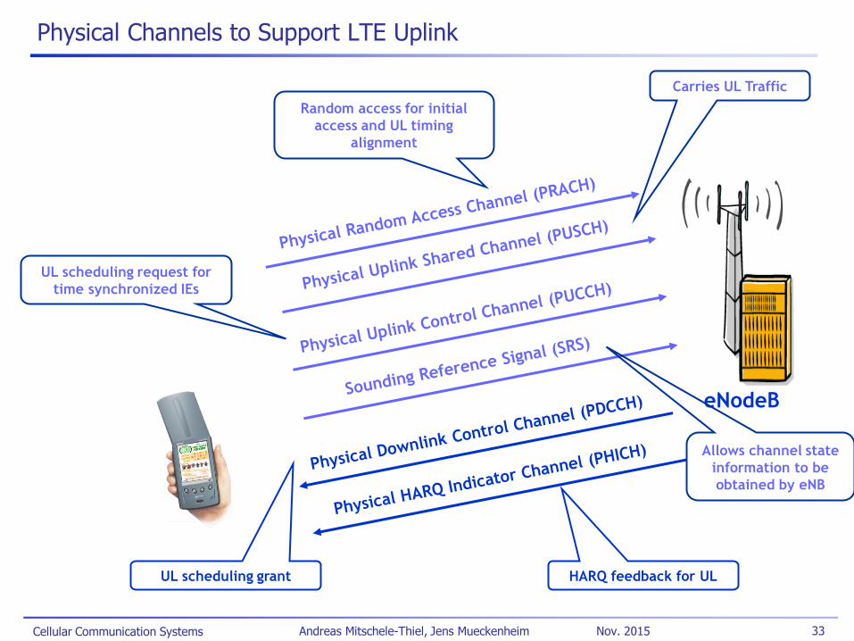
Physical Channels to Support LTE Uplink
eNodeB
Random access for initial
access and UL timing
alignment
UL scheduling grant
Carries UL Traffic
UL scheduling request for
time synchronized IEs
HARQ feedback for UL
Allows channel state
information to be
obtained by eNB
Cellular Communication Systems 34 Andreas Mitschele-Thiel, Jens Mueckenheim Nov. 2015
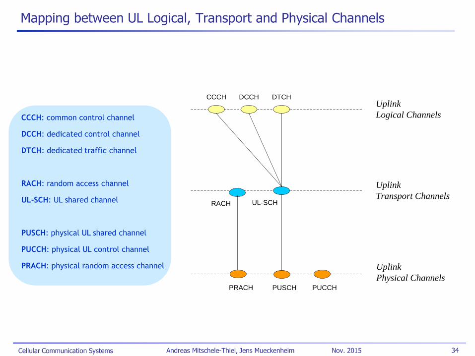
Mapping between UL Logical, Transport and Physical Channels
CCCH DCCH DTCH
RACH UL-SCH
Uplink
Logical Channels
Uplink
Transport Channels
Uplink
Physical ChannelsPUSCH PUCCHPRACH
CCCH: common control channel
DCCH: dedicated control channel
DTCH: dedicated traffic channel
RACH: random access channel
UL-SCH: UL shared channel
PUSCH: physical UL shared channel
PUCCH: physical UL control channel
PRACH: physical random access channel
Cellular Communication Systems 35 Andreas Mitschele-Thiel, Jens Mueckenheim Nov. 2015
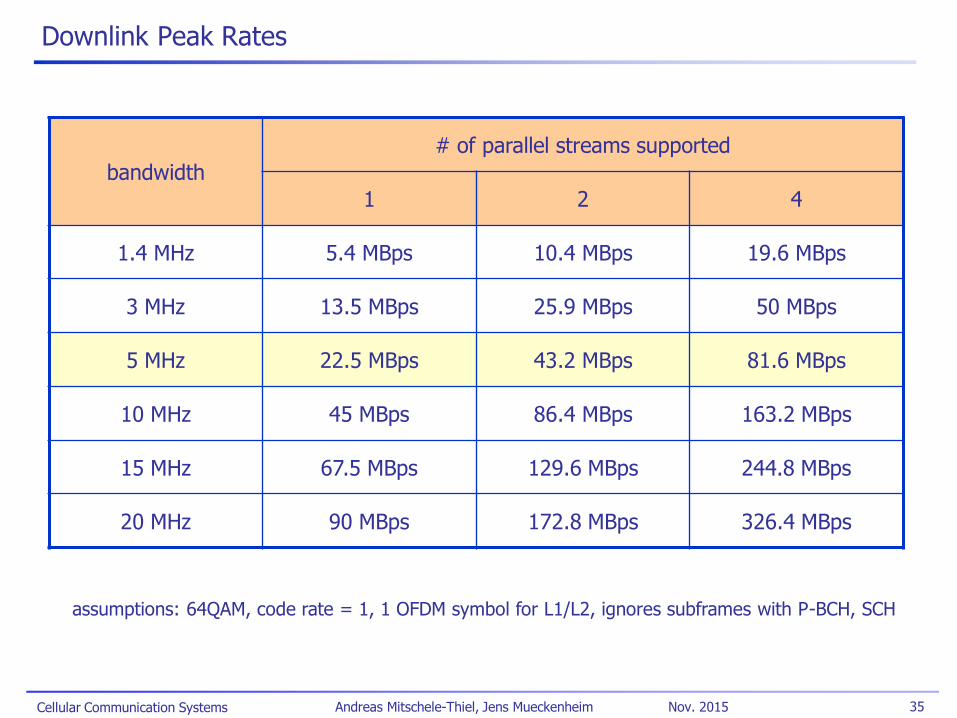
Downlink Peak Rates
bandwidth
# of parallel streams supported
1 2 4
1.4 MHz 5.4 MBps 10.4 MBps 19.6 MBps
3 MHz 13.5 MBps 25.9 MBps 50 MBps
5 MHz 22.5 MBps 43.2 MBps 81.6 MBps
10 MHz 45 MBps 86.4 MBps 163.2 MBps
15 MHz 67.5 MBps 129.6 MBps 244.8 MBps
20 MHz 90 MBps 172.8 MBps 326.4 MBps
assumptions: 64QAM, code rate = 1, 1 OFDM symbol for L1/L2, ignores subframes with P-BCH, SCH

Cellular Communication Systems 36 Andreas Mitschele-Thiel, Jens Mueckenheim Nov. 2015
Uplink Peak Rates
bandwidth
Highest Modulation
16 QAM 64QAM
1.4 MHz 2.9 MBps 4.3 MBps
3 MHz 6.9 MBps 10.4 MBps
5 MHz 11.5 MBps 17.3 MBps
10 MHz 27.6 MBps 41.5 MBps
15 MHz 41.5 MBps 62.2 MBps
20 MHz 55.3 MBps 82.9 MBps
assumptions: code rate = 1, 2 PRBs reserved for PUCCH (1 for 1.4 MHz), no SRS, ignores subframes with PRACH, takes into account highest prime-factor restriction
Cellular Communication Systems 37 Andreas Mitschele-Thiel, Jens Mueckenheim Nov. 2015
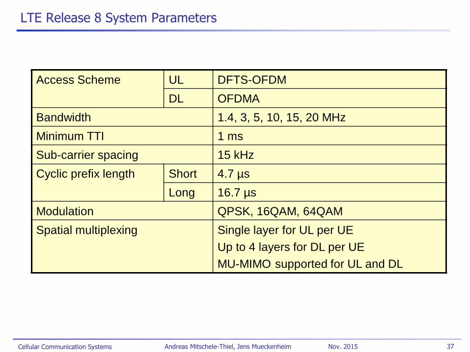
LTE Release 8 System Parameters
Access Scheme UL DFTS-OFDM
DL OFDMA
Bandwidth 1.4, 3, 5, 10, 15, 20 MHz
Minimum TTI 1 ms
Sub-carrier spacing 15 kHz
Cyclic prefix length Short 4.7 µs
Long 16.7 µs
Modulation QPSK, 16QAM, 64QAM
Spatial multiplexing Single layer for UL per UE
Up to 4 layers for DL per UE
MU-MIMO supported for UL and DL

Cellular Communication Systems 38 Andreas Mitschele-Thiel, Jens Mueckenheim Nov. 2015
LTE Release 8 User Equipment Categories
Category 1 2 3 4 5
Peak rate
Mbps
DL 10 50 100 150 300
UL 5 25 50 50 75
Capability for physical functionalities
RF bandwidth 20 MHz
Modulation DL QPSK, 16QAM, 64QAM
UL QPSK, 16QAM QPSK,
16QAM,
64QAM
Multi-antenna
2 Rx diversity Assumed in performance requirements.
2x2 MIMO Not
supported
Mandatory
4x4 MIMO Not supported Mandatory
Cellular Communication Systems 39 Andreas Mitschele-Thiel, Jens Mueckenheim Nov. 2015
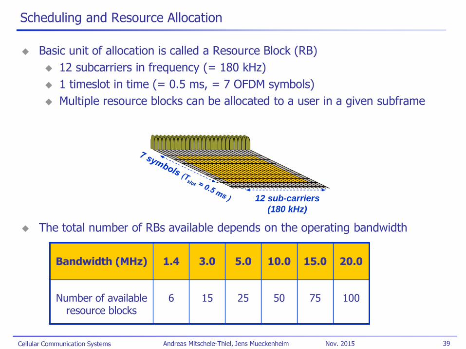
Scheduling and Resource Allocation
Basic unit of allocation is called a Resource Block (RB)
12 subcarriers in frequency (= 180 kHz)
1 timeslot in time (= 0.5 ms, = 7 OFDM symbols)
Multiple resource blocks can be allocated to a user in a given subframe
The total number of RBs available depends on the operating bandwidth
12 sub-carriers
(180 kHz)
Bandwidth (MHz) 1.4 3.0 5.0 10.0 15.0 20.0
Number of available resource blocks
6 15 25 50 75 100
Cellular Communication Systems 40 Andreas Mitschele-Thiel, Jens Mueckenheim Nov. 2015
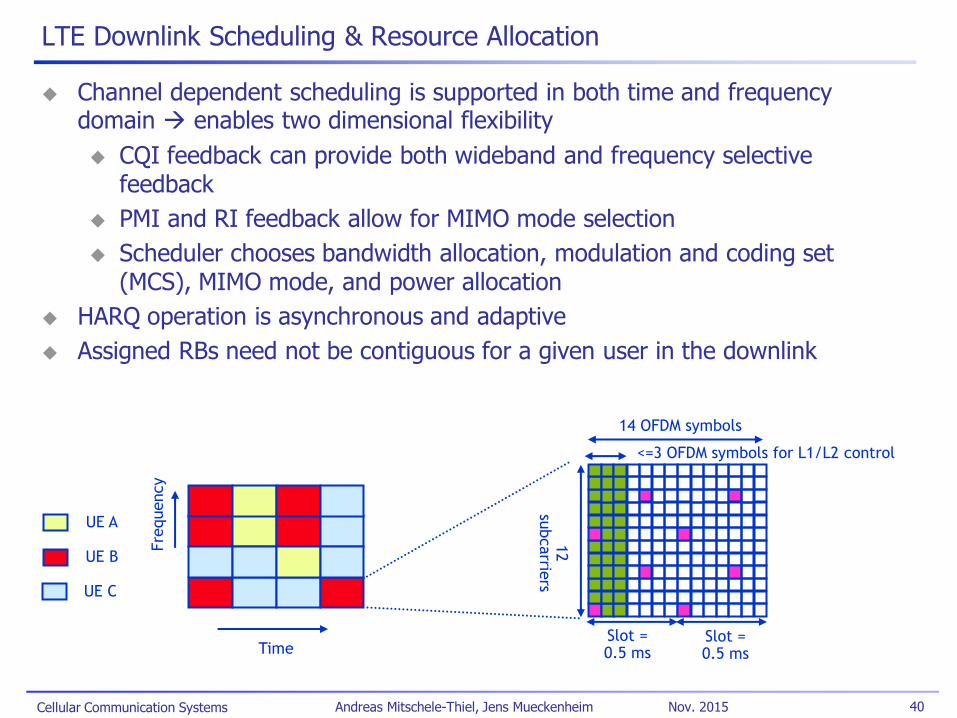
LTE Downlink Scheduling & Resource Allocation
Channel dependent scheduling is supported in both time and frequency domain enables two dimensional flexibility
CQI feedback can provide both wideband and frequency selective feedback
PMI and RI feedback allow for MIMO mode selection
Scheduler chooses bandwidth allocation, modulation and coding set (MCS), MIMO mode, and power allocation
HARQ operation is asynchronous and adaptive
Assigned RBs need not be contiguous for a given user in the downlink
14 OFDM symbols
12
subcarrie
rs
Slot = 0.5 ms
Slot = 0.5 ms
UE A
UE B
UE C
Time
Fre
quency
<=3 OFDM symbols for L1/L2 control
Cellular Communication Systems 41 Andreas Mitschele-Thiel, Jens Mueckenheim Nov. 2015
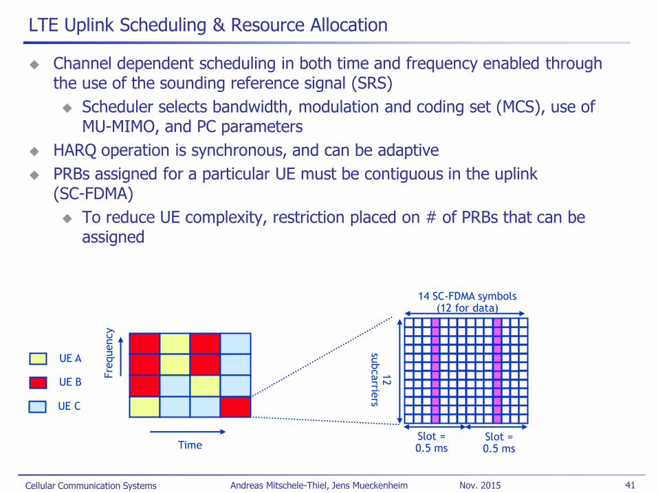
LTE Uplink Scheduling & Resource Allocation
Channel dependent scheduling in both time and frequency enabled through the use of the sounding reference signal (SRS)
Scheduler selects bandwidth, modulation and coding set (MCS), use of MU-MIMO, and PC parameters
HARQ operation is synchronous, and can be adaptive
PRBs assigned for a particular UE must be contiguous in the uplink (SC-FDMA)
To reduce UE complexity, restriction placed on # of PRBs that can be assigned
14 SC-FDMA symbols (12 for data)
12
subcarrie
rs
Slot = 0.5 ms
Slot = 0.5 ms
UE A
UE B
UE C
Time
Fre
quency
Cellular Communication Systems 42 Andreas Mitschele-Thiel, Jens Mueckenheim Nov. 2015
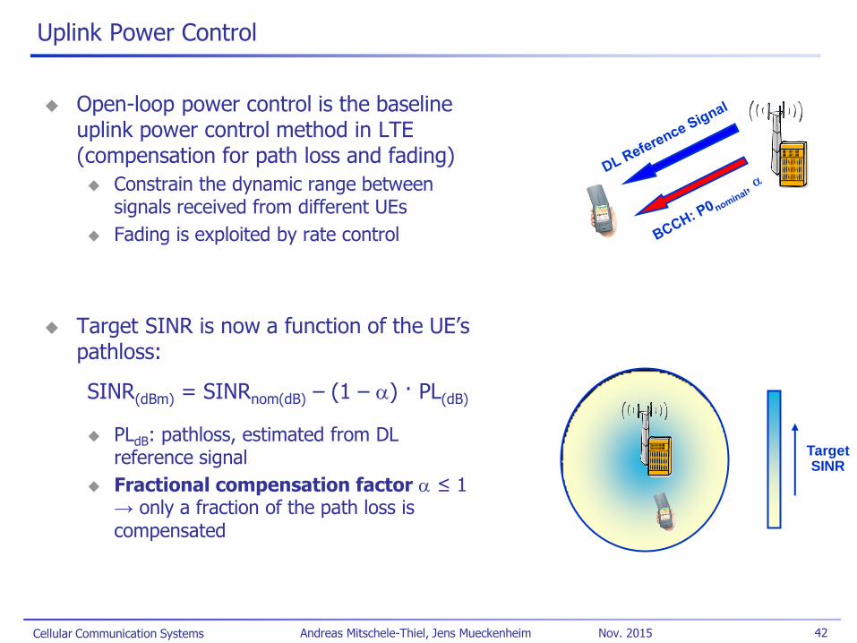
Uplink Power Control
Open-loop power control is the baseline uplink power control method in LTE (compensation for path loss and fading)
Constrain the dynamic range between signals received from different UEs
Fading is exploited by rate control
Target SINR is now a function of the UE’s pathloss:
SINR(dBm) = SINRnom(dB) – (1 – a) · PL(dB)
PLdB: pathloss, estimated from DL reference signal
Fractional compensation factor a ≤ 1 → only a fraction of the path loss is compensated
Target SINR
Cellular Communication Systems 43 Andreas Mitschele-Thiel, Jens Mueckenheim Nov. 2015
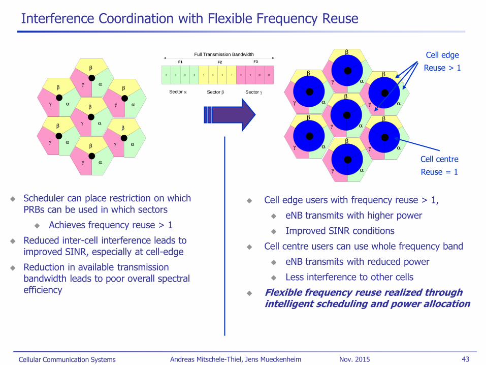
Interference Coordination with Flexible Frequency Reuse
Cell edge users with frequency reuse > 1,
eNB transmits with higher power
Improved SINR conditions
Cell centre users can use whole frequency band
eNB transmits with reduced power
Less interference to other cells
Flexible frequency reuse realized through intelligent scheduling and power allocation
a
b
g
a
b
g
a
b
g
a
b
g
a
b
g
a
b
g
a
b
g
a
b
g
a
b
g
a
b
g
a
b
g
a
b
g
a
b
g
a
b
g
Cell edge
Reuse > 1
Cell centre
Reuse = 1
Scheduler can place restriction on which PRBs can be used in which sectors
Achieves frequency reuse > 1
Reduced inter-cell interference leads to improved SINR, especially at cell-edge
Reduction in available transmission bandwidth leads to poor overall spectral efficiency
0 1 2 3 4 5 6 7 8 9 10 11
Sector a Sector b Sector g
F1 F2 F3
Full Transmission Bandwidth
Cellular Communication Systems 44 Andreas Mitschele-Thiel, Jens Mueckenheim Nov. 2015
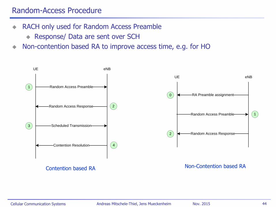
Random-Access Procedure
RACH only used for Random Access Preamble
Response/ Data are sent over SCH
Non-contention based RA to improve access time, e.g. for HO
UE eNB
RA Preamble assignment0
Random Access Preamble 1
Random Access Response2
UE eNB
Random Access Preamble1
Random Access Response 2
Scheduled Transmission3
Contention Resolution 4
Contention based RA Non-Contention based RA
Cellular Communication Systems 45 Andreas Mitschele-Thiel, Jens Mueckenheim Nov. 2015
LTE Handover
LTE uses mobile-assisted & network-controlled handover
UE reports measurements using reporting criteria
Network decides when handover and to which cell
Relies on UE to detect neighbor cells no need to maintain and broadcast neighbor lists
Allows "plug-and-play" capability; saves BCH resources
For search and measurement of inter-frequency neighboring cells only carrier frequency need to be indicated
X2 interface used for handover preparation and forwarding of user data
Target eNB prepares handover by sending required information to UE transparently through source eNB as part of the Handover Request Acknowledge message
New configuration information needed from system broadcast
Accelerates handover as UE does not need to read BCH on target cell
Buffered and new data is transferred from source to target eNB until path switch prevents data loss
UE uses contention-free random access to accelerate handover
Cellular Communication Systems 46 Andreas Mitschele-Thiel, Jens Mueckenheim Nov. 2015
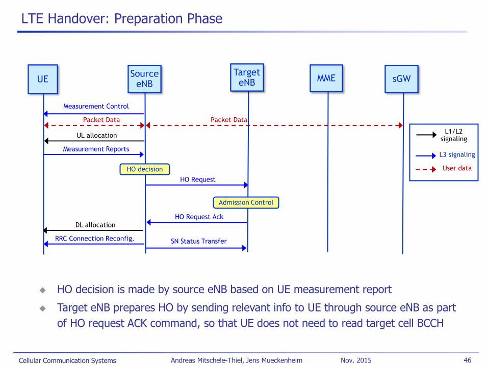
LTE Handover: Preparation Phase
UE UE Source
eNB Source
eNB
Measurement Control
Target eNB
Target eNB MME MME sGW sGW
Packet Data Packet Data
UL allocation
Measurement Reports
HO decision
Admission Control
HO Request
HO Request Ack
DL allocation
RRC Connection Reconfig.
L1/L2 signaling
L3 signaling
User data
HO decision is made by source eNB based on UE measurement report
Target eNB prepares HO by sending relevant info to UE through source eNB as part
of HO request ACK command, so that UE does not need to read target cell BCCH
SN Status Transfer
Cellular Communication Systems 47 Andreas Mitschele-Thiel, Jens Mueckenheim Nov. 2015
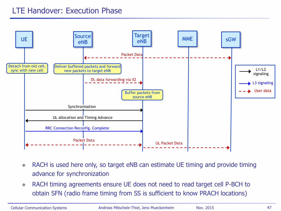
LTE Handover: Execution Phase
UE UE Source
eNB Source
eNB
Target eNB
Target eNB MME MME sGW sGW
Detach from old cell, sync with new cell
Deliver buffered packets and forward new packets to target eNB
DL data forwarding via X2
Synchronisation
UL allocation and Timing Advance
RRC Connection Reconfig. Complete
L1/L2 signaling
L3 signaling
User data Buffer packets from
source eNB
Packet Data
Packet Data
RACH is used here only, so target eNB can estimate UE timing and provide timing
advance for synchronization
RACH timing agreements ensure UE does not need to read target cell P-BCH to
obtain SFN (radio frame timing from SS is sufficient to know PRACH locations)
UL Packet Data

Cellular Communication Systems 48 Andreas Mitschele-Thiel, Jens Mueckenheim Nov. 2015
LTE Handover: Completion Phase
UE UE Source
eNB
Target eNB
Target eNB MME MME sGW sGW
DL Packet Data
Path switch req
User plane update req
Switch DL path
User plane update response Path switch req ACK
Release resources
Packet Data Packet Data
L1/L2 signaling
L3 signaling
User data
DL data forwarding
Flush DL buffer, continue delivering in-transit packets
End Marker
Release resources
Packet Data
End Marker
Cellular Communication Systems 49 Andreas Mitschele-Thiel, Jens Mueckenheim Nov. 2015
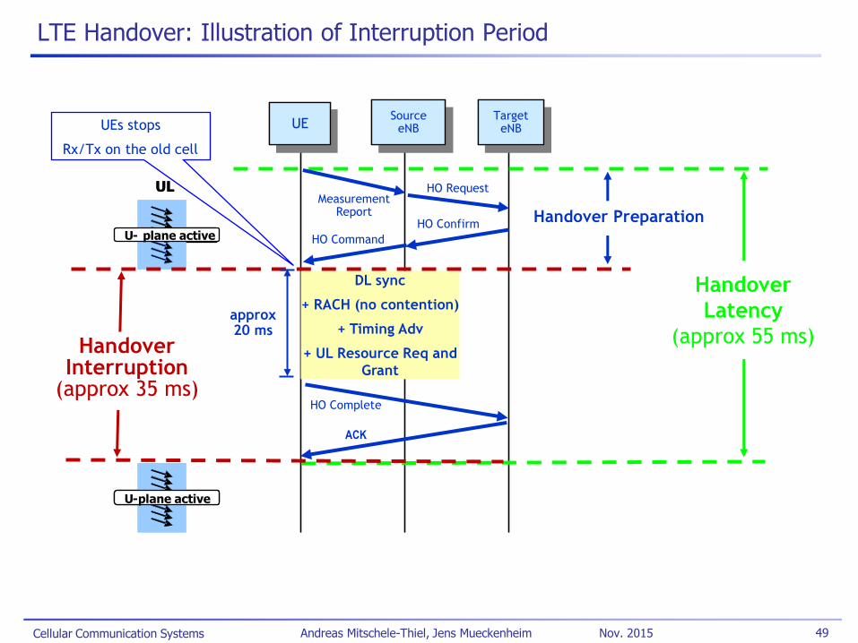
LTE Handover: Illustration of Interruption Period
UL
U - plane active
U - plane active
UE UE Source
eNB Source
eNB Target eNB
Target eNB
UL
U - plane active
U - plane active
UEs stops
Rx/Tx on the old cell
DL sync
+ RACH (no contention)
+ Timing Adv
+ UL Resource Req and
Grant
ACK
HO Request
HO Confirm
Handover
Latency
(approx 55 ms) approx 20 ms
Measurement Report
HO Command
HO Complete
Handover Interruption
(approx 35 ms)
Handover Preparation
Cellular Communication Systems 50 Andreas Mitschele-Thiel, Jens Mueckenheim Nov. 2015
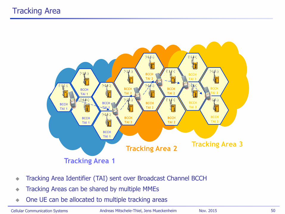
Tracking Area
BCCH
TAI 1
BCCH
TAI 1
BCCH
TAI 1
BCCH
TAI 1
BCCH
TAI 1
BCCH
TAI 2
BCCH
TAI 2
BCCH
TAI 2
BCCH
TAI 2
BCCH
TAI 2
BCCH
TAI 2
BCCH
TAI 3
BCCH
TAI 3
BCCH
TAI 3
BCCH
TAI 3
Tracking Area 1
Tracking Area 2 Tracking Area 3
Tracking Area Identifier (TAI) sent over Broadcast Channel BCCH
Tracking Areas can be shared by multiple MMEs
One UE can be allocated to multiple tracking areas
Cellular Communication Systems 51 Andreas Mitschele-Thiel, Jens Mueckenheim Nov. 2015
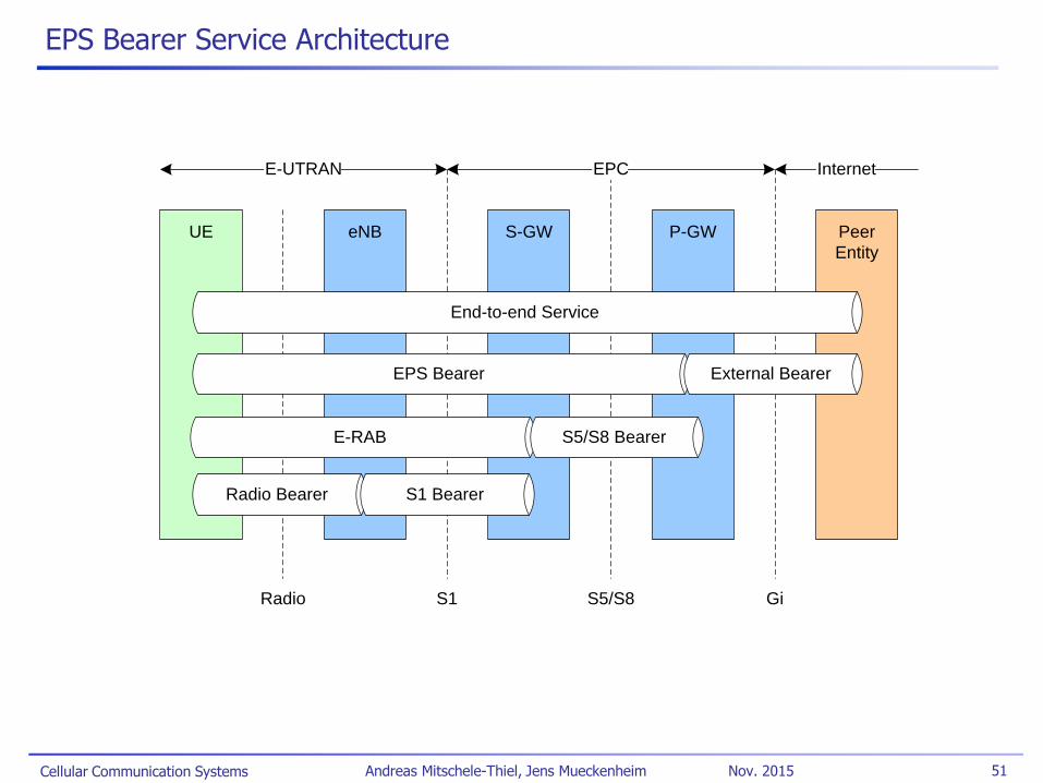
EPS Bearer Service Architecture
P-GWS-GW Peer
Entity
UE eNB
EPS Bearer
Radio Bearer S1 Bearer
End-to-end Service
External Bearer
Radio S5/S8
Internet
S1
E-UTRAN EPC
Gi
E-RAB S5/S8 Bearer
Cellular Communication Systems 52 Andreas Mitschele-Thiel, Jens Mueckenheim Nov. 2015
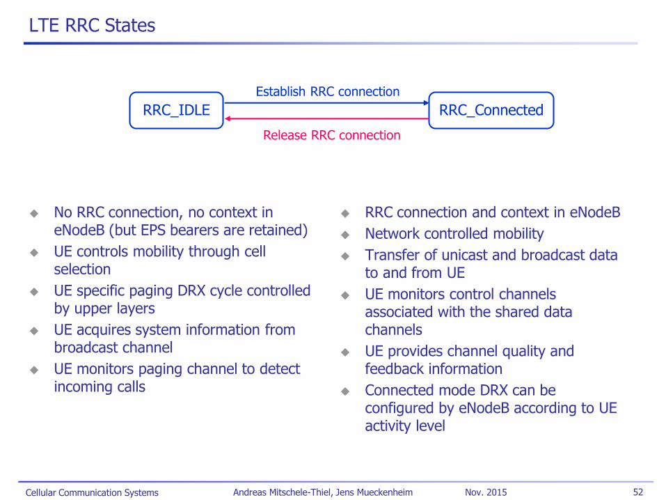
LTE RRC States
No RRC connection, no context in eNodeB (but EPS bearers are retained)
UE controls mobility through cell selection
UE specific paging DRX cycle controlled by upper layers
UE acquires system information from broadcast channel
UE monitors paging channel to detect incoming calls
RRC connection and context in eNodeB
Network controlled mobility
Transfer of unicast and broadcast data to and from UE
UE monitors control channels associated with the shared data channels
UE provides channel quality and feedback information
Connected mode DRX can be configured by eNodeB according to UE activity level
RRC_IDLE RRC_Connected
Release RRC connection
Establish RRC connection
Cellular Communication Systems 53 Andreas Mitschele-Thiel, Jens Mueckenheim Nov. 2015
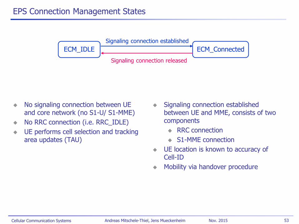
EPS Connection Management States
No signaling connection between UE and core network (no S1-U/ S1-MME)
No RRC connection (i.e. RRC_IDLE)
UE performs cell selection and tracking area updates (TAU)
Signaling connection established between UE and MME, consists of two components
RRC connection
S1-MME connection
UE location is known to accuracy of Cell-ID
Mobility via handover procedure
ECM_IDLE ECM_Connected
Signaling connection released
Signaling connection established
Cellular Communication Systems 54 Andreas Mitschele-Thiel, Jens Mueckenheim Nov. 2015
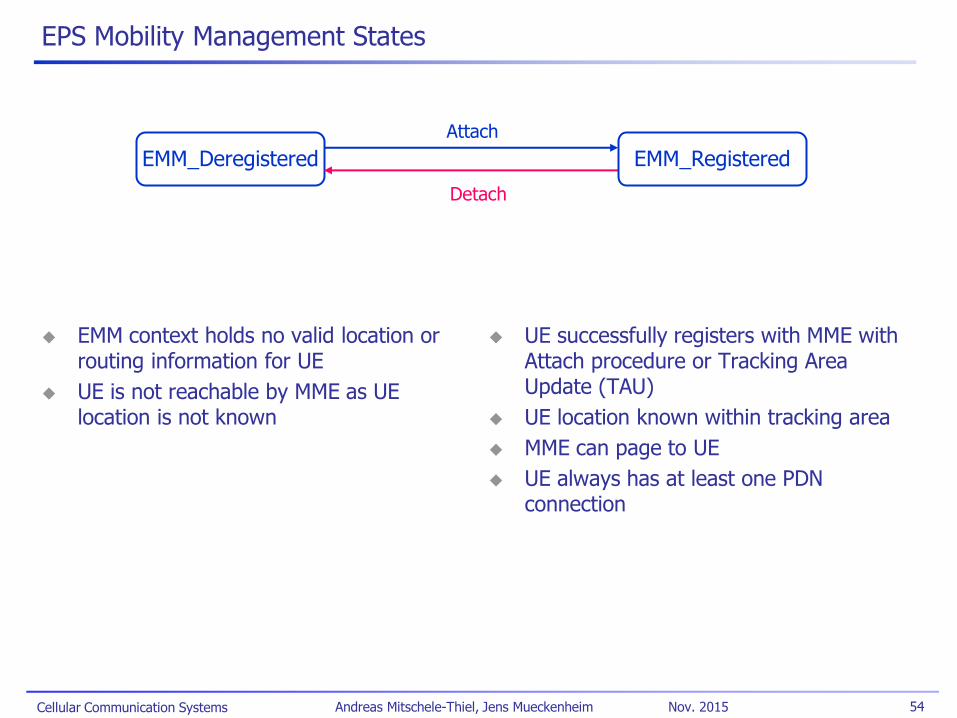
EPS Mobility Management States
EMM context holds no valid location or routing information for UE
UE is not reachable by MME as UE location is not known
UE successfully registers with MME with Attach procedure or Tracking Area Update (TAU)
UE location known within tracking area
MME can page to UE
UE always has at least one PDN connection
EMM_Deregistered
Detach
Attach
EMM_Registered
Cellular Communication Systems 55 Andreas Mitschele-Thiel, Jens Mueckenheim Nov. 2015
LTE – Status
LTE standards are stable
Rel.8 frozen in 2Q2009
Since 2010, LTE has been deployed worldwide
Totally new infrastructure
First target was often to provide broadband coverage for fixed users
Currently, 430 LTE networks in 145 countries are in service (Nov. 2015)*
Mostly implemented according to Release 8/9, start of LTE-Advanced
Mostly FDD, but also some TDD networks
Mobile packet data support with fallback to 3G/2G for CS voice service
Spectrum allocation in new frequency bands as well as existing 2G/3G bands (refarming)
3GPP continues LTE development
Rel.9: technical enhancements/ E-MBMS
Rel.10 – 12: LTE-Advanced (cf. next slides)
*http://www.4gamericas.org -> Statistics
Cellular Communication Systems 56 Andreas Mitschele-Thiel, Jens Mueckenheim Nov. 2015
LTE-Advanced
The evolution of LTE
Corresponding to LTE Release 10 and beyond
Motivation of LTE-Advanced
IMT-Advanced standardisation process in ITU-R
Additional IMT spectrum band identified in WRC07
Further evolution of LTE Release 8 and 9 to meet:
Performance requirements for IMT-Advanced of ITU-R
Future operator and end-user requirements
Other important requirements
LTE-Advanced to be backwards compatible with Release 8
Support for flexible deployment scenarios including downlink/uplink asymmetric bandwidth allocation for FDD and non-contiguous spectrum allocation
Increased deployment of indoor eNB and HNB in LTE-Advanced
Cf. T. Nakamura (RAN chairman): “Proposal for Candidate Radio Interface Technologies for IMT-Advanced Based on LTE Release 10 and Beyond LTE-Advanced),” ITU-R WP 5D 3rd Workshop on IMT-Advanced, October 2009.
Cellular Communication Systems 57 Andreas Mitschele-Thiel, Jens Mueckenheim Nov. 2015
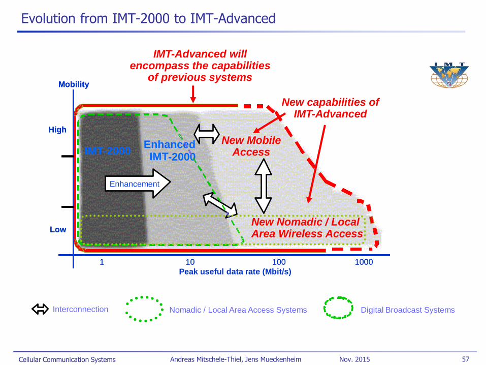
Evolution from IMT-2000 to IMT-Advanced
Interconnection
IMT - 2000
Mobility
Low
High
1 10 100 1000
Peak useful data rate (Mbit/s)
Enhanced IMT - 2000
Enhancement
IMT - 2000
Mobility
Low
High
1 10 100 1000
Area Wireless Access
Enhanced IMT - 2000
Enhancement
Digital Broadcast Systems Nomadic / Local Area Access Systems
New Nomadic / Local
IMT-Advanced will encompass the capabilities
of previous systems
New capabilities of IMT-Advanced
New Mobile Access
Cellular Communication Systems 58 Andreas Mitschele-Thiel, Jens Mueckenheim Nov. 2015
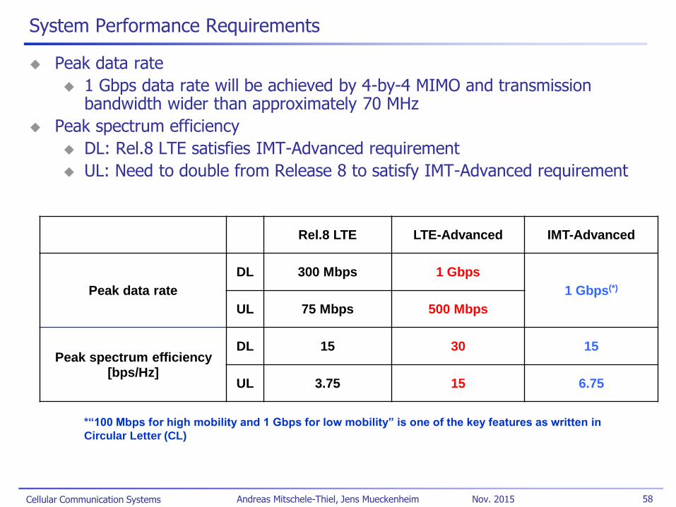
Peak data rate
1 Gbps data rate will be achieved by 4-by-4 MIMO and transmission bandwidth wider than approximately 70 MHz
Peak spectrum efficiency
DL: Rel.8 LTE satisfies IMT-Advanced requirement
UL: Need to double from Release 8 to satisfy IMT-Advanced requirement
Rel.8 LTE LTE-Advanced IMT-Advanced
Peak data rate
DL 300 Mbps 1 Gbps
1 Gbps(*)
UL 75 Mbps 500 Mbps
Peak spectrum efficiency [bps/Hz]
DL 15 30 15
UL 3.75 15 6.75
*“100 Mbps for high mobility and 1 Gbps for low mobility” is one of the key features as written in
Circular Letter (CL)
System Performance Requirements

Cellular Communication Systems 59 Andreas Mitschele-Thiel, Jens Mueckenheim Nov. 2015
Technical Outline to Achieve LTE-Advanced Requirements
Support wider bandwidth
Carrier aggregation to achieve wider bandwidth
Support of spectrum aggregation
Peak data rate, spectrum flexibility
Advanced MIMO techniques
Extension to up to 8-layer transmission in downlink
Introduction of single-user MIMO up to 4-layer transmission in uplink
Peak data rate, capacity, cell-edge user throughput
Coordinated multipoint transmission and reception (CoMP)
CoMP transmission in downlink
CoMP reception in uplink
Cell-edge user throughput, coverage, deployment flexibility
Relaying
Type 1 relays create a separate cell and appear as Rel.8 LTE eNB to Rel.8 LTE UEs
Coverage, cost effective deployment
Cellular Communication Systems 60 Andreas Mitschele-Thiel, Jens Mueckenheim Nov. 2015
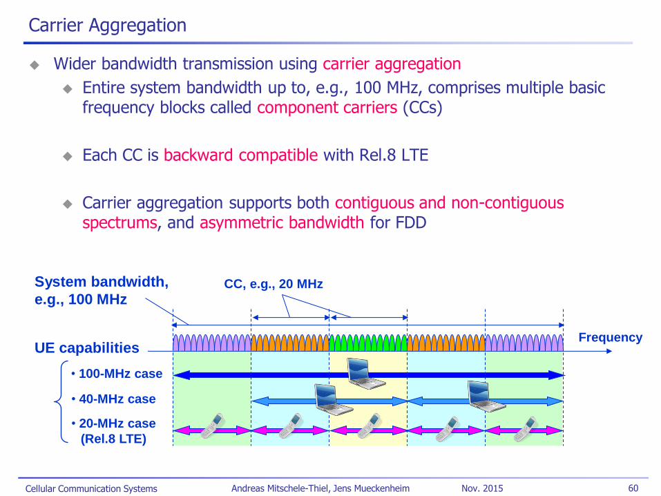
Wider bandwidth transmission using carrier aggregation
Entire system bandwidth up to, e.g., 100 MHz, comprises multiple basic frequency blocks called component carriers (CCs)
Each CC is backward compatible with Rel.8 LTE
Carrier aggregation supports both contiguous and non-contiguous spectrums, and asymmetric bandwidth for FDD
Frequency
System bandwidth,
e.g., 100 MHz CC, e.g., 20 MHz
UE capabilities
• 100-MHz case
• 40-MHz case
• 20-MHz case
(Rel.8 LTE)
Carrier Aggregation
Cellular Communication Systems 61 Andreas Mitschele-Thiel, Jens Mueckenheim Nov. 2015
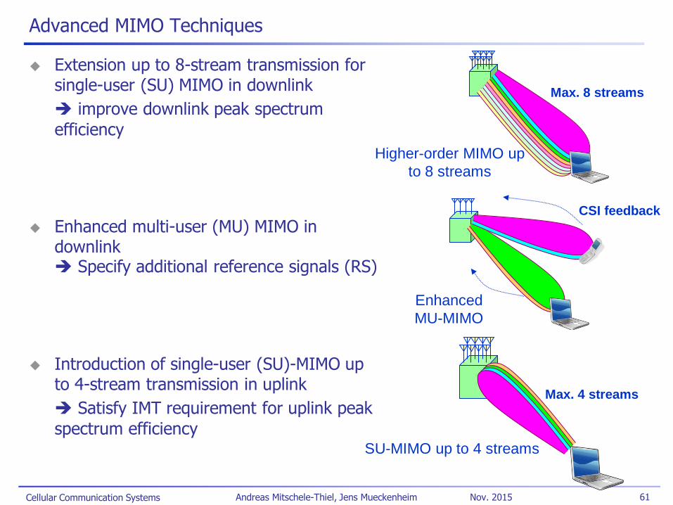
Advanced MIMO Techniques
Extension up to 8-stream transmission for single-user (SU) MIMO in downlink
improve downlink peak spectrum
efficiency
Enhanced multi-user (MU) MIMO in downlink Specify additional reference signals (RS)
Introduction of single-user (SU)-MIMO up to 4-stream transmission in uplink
Satisfy IMT requirement for uplink peak
spectrum efficiency
Max. 8 streams
Higher-order MIMO up
to 8 streams
Enhanced
MU-MIMO
CSI feedback
Max. 4 streams
SU-MIMO up to 4 streams
Cellular Communication Systems 62 Andreas Mitschele-Thiel, Jens Mueckenheim Nov. 2015
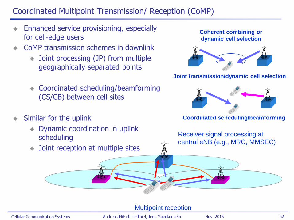
Coordinated Multipoint Transmission/ Reception (CoMP)
Enhanced service provisioning, especially for cell-edge users
CoMP transmission schemes in downlink
Joint processing (JP) from multiple geographically separated points
Coordinated scheduling/beamforming (CS/CB) between cell sites
Similar for the uplink
Dynamic coordination in uplink scheduling
Joint reception at multiple sites
Coherent combining or
dynamic cell selection
Joint transmission/dynamic cell selection
Coordinated scheduling/beamforming
Receiver signal processing at
central eNB (e.g., MRC, MMSEC)
Multipoint reception
Cellular Communication Systems 63 Andreas Mitschele-Thiel, Jens Mueckenheim Nov. 2015
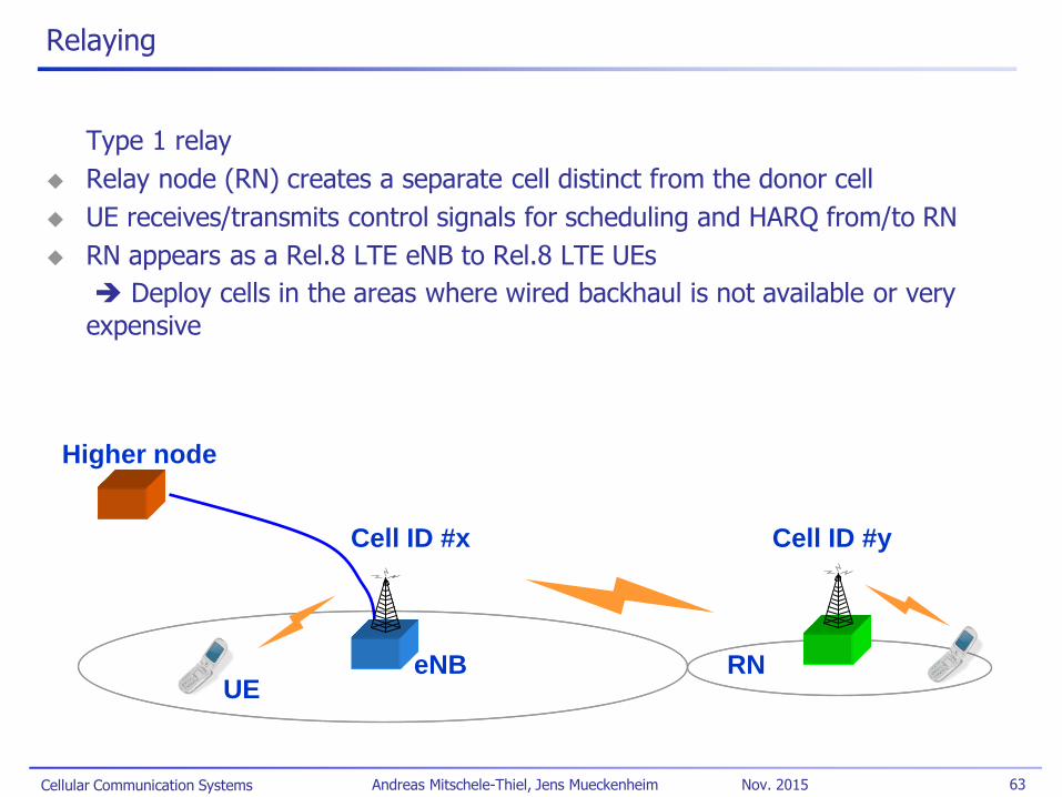
eNB RN UE
Cell ID #x Cell ID #y
Higher node
Relaying
Type 1 relay
Relay node (RN) creates a separate cell distinct from the donor cell
UE receives/transmits control signals for scheduling and HARQ from/to RN
RN appears as a Rel.8 LTE eNB to Rel.8 LTE UEs
Deploy cells in the areas where wired backhaul is not available or very
expensive
Cellular Communication Systems 64 Andreas Mitschele-Thiel, Jens Mueckenheim Nov. 2015
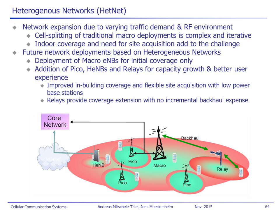
Heterogenous Networks (HetNet)
Network expansion due to varying traffic demand & RF environment Cell-splitting of traditional macro deployments is complex and iterative Indoor coverage and need for site acquisition add to the challenge
Future network deployments based on Heterogeneous Networks Deployment of Macro eNBs for initial coverage only Addition of Pico, HeNBs and Relays for capacity growth & better user
experience Improved in-building coverage and flexible site acquisition with low power
base stations Relays provide coverage extension with no incremental backhaul expense

Cellular Communication Systems 65 Andreas Mitschele-Thiel, Jens Mueckenheim Nov. 2015
LTE References
Literature:
H. Holma/ A. Toskala (Ed.): “LTE for UMTS - Evolution to LTE-Advanced,” 2nd edition, Wiley 2011
E. Dahlman et al: “4G: LTE/LTE-Advanced for Mobile Broadband,” 2nd edition, Academic Press 2013
S. Sesia et al: “LTE, The UMTS Long Term Evolution: From Theory to Practice,” Wiley 2011
H. Holma/ A. Toskala (Ed.): “LTE Advanced: 3GPP Solution for IMT-Advanced,” Wiley 2012
Standards
TS 36.xxx series: RAN Aspects
TS 36.300 “E-UTRAN; Overall description; Stage 2”
TR 25.912 “Feasibility study for evolved Universal Terrestrial Radio Access (UTRA) and Universal Terrestrial Radio Access Network (UTRAN)”
TR 25.814 “Physical layer aspect for evolved UTRA”
TR 23.882 “3GPP System Architecture Evolution: Report on Technical Options and Conclusions”
TR 36.912 “Feasibility study for Further Advancements for E-UTRA (LTE-Advanced)”
TR 36.814 “Further Advancements for E-UTRA – Physical Layer Aspects”
Cellular Communication Systems 66 Andreas Mitschele-Thiel, Jens Mueckenheim Nov. 2015
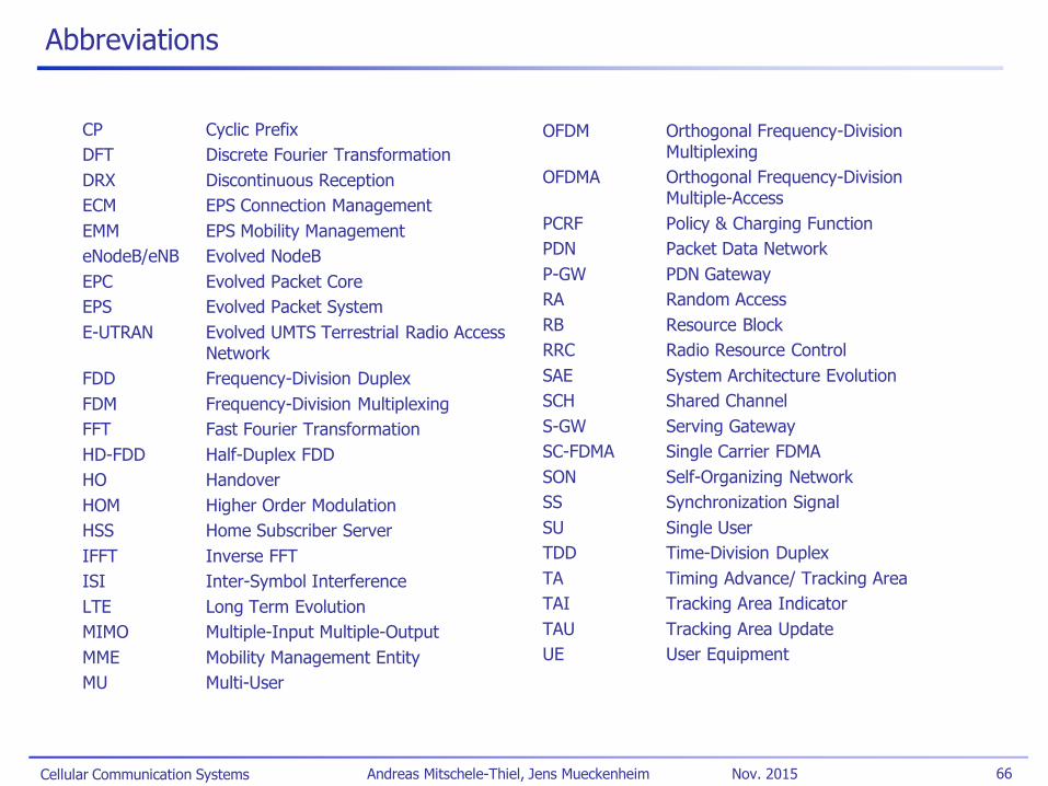
Abbreviations
CP Cyclic Prefix
DFT Discrete Fourier Transformation
DRX Discontinuous Reception
ECM EPS Connection Management
EMM EPS Mobility Management
eNodeB/eNB Evolved NodeB
EPC Evolved Packet Core
EPS Evolved Packet System
E-UTRAN Evolved UMTS Terrestrial Radio Access Network
FDD Frequency-Division Duplex
FDM Frequency-Division Multiplexing
FFT Fast Fourier Transformation
HD-FDD Half-Duplex FDD
HO Handover
HOM Higher Order Modulation
HSS Home Subscriber Server
IFFT Inverse FFT
ISI Inter-Symbol Interference
LTE Long Term Evolution
MIMO Multiple-Input Multiple-Output
MME Mobility Management Entity
MU Multi-User
OFDM Orthogonal Frequency-Division Multiplexing
OFDMA Orthogonal Frequency-Division Multiple-Access
PCRF Policy & Charging Function
PDN Packet Data Network
P-GW PDN Gateway
RA Random Access
RB Resource Block
RRC Radio Resource Control
SAE System Architecture Evolution
SCH Shared Channel
S-GW Serving Gateway
SC-FDMA Single Carrier FDMA
SON Self-Organizing Network
SS Synchronization Signal
SU Single User
TDD Time-Division Duplex
TA Timing Advance/ Tracking Area
TAI Tracking Area Indicator
TAU Tracking Area Update
UE User Equipment