Embed Size (px)
Citation preview
Long-distance free-space quantum key distributionin daylight towards inter-satellite communicationSheng-Kai Liao1,2†, Hai-Lin Yong1,2†, Chang Liu1,2†, Guo-Liang Shentu1,2†, Dong-Dong Li1,2, Jin Lin1,2,Hui Dai1,2, Shuang-Qiang Zhao3, Bo Li1,2, Jian-Yu Guan1,2, Wei Chen1,2, Yun-Hong Gong1,2, Yang Li1,2,Ze-Hong Lin3, Ge-Sheng Pan1,2, Jason S. Pelc4, M. M. Fejer4, Wen-Zhuo Zhang1,2, Wei-Yue Liu3,Juan Yin1,2, Ji-Gang Ren1,2, Xiang-Bin Wang2,5, Qiang Zhang1,2,5*, Cheng-Zhi Peng1,2*and Jian-Wei Pan1,2*
In the past, long-distance free-space quantum communication experiments could only be implemented at night. During thedaytime, the bright background sunlight prohibits quantum communication in transmission under conditions of highchannel loss over long distances. Here, by choosing a working wavelength of 1,550 nm and developing free-space single-mode fibre-coupling technology and ultralow-noise upconversion single-photon detectors, we have overcome the noise dueto sunlight and demonstrate free-space quantum key distribution over 53 km during the day. The total channel loss is∼48 dB, which is greater than the 40 dB channel loss between the satellite and ground and between low-Earth-orbitsatellites. Our system thus demonstrates the feasibility of satellite-based quantum communication in daylight. Moreover,given that our working wavelength is located in the optical telecom band, our system is naturally compatible with groundfibre networks and thus represents an essential step towards a satellite-constellation-based global quantum network.
Satellite-based quantum communication has proven to be a feas-ible way to achieve a global-scale quantum communicationnetwork1–9. Very recently, a low-Earth-orbit (LEO) satellite
was launched10 for this purpose. However, with a single satellite,an inefficient 3 day period11 is required to provide worldwide con-nectivity. On the other hand, similar to how the Iridium system12
functions in classical communication, a satellite constellation(SC) composed of many quantum satellites could provide globalreal-time quantum communication. Such an SC is expected tooperate with LEO satellites or high-Earth-orbit satellites suchas geosynchronous orbit (GEO) satellites. The probability of asatellite being in the Earth shadow zone decreases rapidly withincreasing orbit height (Fig. 1). A LEO satellite system has aprobability of ∼70% of being in the sunlight zone, whereas for aGEO satellite this rises to ∼99% (ref. 13). Meanwhile, the totalchannel loss between a LEO satellite and the Earth and betweenLEO satellites is typically ∼40–45 dB (refs 14,15). Therefore, totest the feasibility of an SC-based quantum network, quantumcommunication through a channel with at least ≥40 dB loss indaylight is essential.
There have been several pioneering experiments on daylightquantum communication before our work16–22. Although the exper-iments were novel, the maximum loss calculated from them wasonly ∼20 dB. The main cause of the unsatisfactory performancewas the strong background noise from the scattered sunlight,which was typically five orders of magnitude greater than the back-ground noise during the night23. We can reduce this noise in threeways: working wavelength selection, spectrum filtering andspatial filtering.
Working wavelength selectionWe first switched the working wavelength to 1,550.14 nm from the700–900 nm used in all previous experiments. The 1,550 nm wave-length is known to be an atmospheric window. In fact, the trans-mission efficiency is slightly higher at 1,550 nm than at 800 nm,as shown in Fig. 1a, and from the solar spectrum in Fig. 1b wecan see that the sunlight intensity at 1,550 nm is around five timesweaker than it is at 800 nm. Furthermore, the main type of scatteringof solar noise for links between a satellite and Earth or between twosatellites is Rayleigh scattering, the intensity of which is proportionalto 1/λ4. Therefore, Rayleigh scattering at 1,550 nm is only 7% of itsvalue at 800 nm. In total, the background noise with 1,550 nm lightcan be reduced to 3% of the background noise of 800 nm light. Wemeasured the noise count rate of 1,550 nm light in the daylight caseby pointing a telescope at the sky to simulate satellite-to-Earthcommunication. The result was smaller by a factor of 22.5 than for850 nm light. Note that all existing free-space experiments withouta satellite, including this work, have been implemented on Earth,and the direction of the free-space communication is parallel tothe Earth rather than pointing at the sky. In this situation, Mie scat-tering, which does not follow the 1/λ4 relation, will be the main noisesource instead of Rayleigh scattering. Moreover, 1,550 nm is thetelecom-band wavelength and is widely used for fibre-optical com-munication. Using the same wavelength for both free-space andfibre-optical communication is an optimal choice.
Upconversion detectors and spectral filteringDespite the advantages of operating at 1,550 nm, researchers havebeen reluctant to use this wavelength due to a lack of good
1Shanghai Branch, National Laboratory for Physical Sciences at Microscale and Department of Modern Physics, University of Science and Technology ofChina, Shanghai 201315, China. 2Synergetic Innovation Center of Quantum Information and Quantum Physics, University of Science and Technology ofChina, Shanghai 201315, China. 3School of Information Science and Engineering, Ningbo University, Ningbo 315211, China. 4Edward L. Ginzton Laboratory,Stanford University, Stanford, California 94305, USA. 5Jinan Institute of Quantum Technology, Shandong Academy of Information and CommunicationTechnology, Jinan 250101, China. †These authors contributed equally to this work. *e-mail: [email protected]; [email protected]; [email protected]
ARTICLESPUBLISHED ONLINE: 24 JULY 2017 | DOI: 10.1038/NPHOTON.2017.116
NATURE PHOTONICS | ADVANCE ONLINE PUBLICATION | www.nature.com/naturephotonics 1
© 2017 Macmillan Publishers Limited, part of Springer Nature. All rights reserved.

commercial single-photon detectors for the telecom band. We havedeveloped a compact upconversion single-photon detector (SPD)24
(Fig. 2e). In this detector, a telecom-band photon is mixed with astrong pumping signal photon of 1,950 nm in a wavelength divisionmultiplexing (WDM) coupler and then sent to a fibre-pigtailedperiodically poled lithium niobate (PPLN) waveguide. The gener-ated photons are collected by an anti-reflection-coated objectivelens and then separated from the pump and the spurious light bya dichroic mirror (DM), a short-pass filter and a bandpass filter.A volume Bragg grating (VBG) with 95% reflection efficiency isused to further suppress the noise from both spontaneous Ramanscattering generated in the nonlinear process and the sunlight back-ground. The sum-frequency generation (SFG) photons are then col-lected and detected by a silicon avalanche photodiode (SAPD).Using a pump power of 200 mW, the total system detection effi-ciency is 8%, with an average dark count rate of ∼20 Hz, which isthe same as the intrinsic dark count of the SAPD.
Note that, in our experiment, the spectral bandwidth of the VBGfilter is 0.05 nm (full-width at half-maximum, FWHM) at a centrewavelength tunable near 864 nm, corresponding to a bandwidthof 0.16 nm at the signal wavelength. The phase-matching conditionand VBG of the detector itself realize spectrum filtering. Meanwhile,stable distributed feedback lasers (DFBs) with a 2 GHz bandwidthare used as the signal source, which guarantees that no signal willbe filtered out. Such a narrowband filtering technology reducesthe noise by a factor of about 100 compared with the 3–10 nmfilters used in previous night experiments.
Spatial filtering with single-mode fibre couplingTo further improve the signal-to-noise ratio (SNR) we reduced thefield of view (FOV) for our receiving system for spatial filtering. Forfree-space quantum communication at night, the FOV is usually
designed to be ∼100 μrad (refs 2,4,5). In most previous daylightquantum key distribution (QKD) experiments, a similarly largeFOV was also used to improve the coupling efficiency at the receiver(for example, 220 μrad)17. However, the larger the FOV, the largerthe noise introduced to the receiver. Using a single-mode fibre(SMF) to couple the signal photons is an extreme way to improvethe SNR in spatial filtering, with a FOV of <10 μrad. With SMFcoupling, the noise count introduced by stray light can be reducedby a factor of several hundred.
At the same time, the coupling efficiency must be maintained at ahigh level to make the SNR of the experiment larger. In previousexperiments25, ∼0.1% SMF coupling efficiency has been achieved,which is insufficient for quantum communication. We thereforedeveloped the SMF coupling technique further.
Unlike previous free-space experiments, which required manyoptical elements6,7, we used the minimal amount of optics todesign the receiving telescope and to reduce the optical attenuationand aberration. The focal length of the off-axis primary mirror wasset to 2,000 mm to optimize the SMF coupling efficiency. Welocated only one fast-steering mirror (FSM) and one DM betweenthe primary mirror and the SMF, and we developed an optical track-ing system with 300 Hz feedback frequency to stabilize the SMFcoupling (see Supplementary Information). With this set-up wecould obtain a SMF coupling efficiency of >30% in the laboratory,while in the outdoor experiment the SMF coupling efficiency wasreduced to 5% by horizontal air turbulence (with 3 μrad trackingprecision). We emphasize that this 5% efficiency is still muchhigher than the 0.1% efficiency achieved in previous experiments25.Furthermore, in future ground-to-satellite experiments we willreceive signals vertically, and the turbulence is weaker. An efficiencyof 30%, similar to that obtained in the laboratory test, canbe expected.
0.40.00.1
0.20.30.40.5
Tran
smitt
ance
0.60.70.80.91.0
Zenith angle = 0°Zenith angle = 45°
Zenith angle = 30°Zenith angle = 70°
0.6 0.8 1.0
810 nm
2.01.2Wavelength (µm)
1.4
1,550 nm
1.6 1.8
250
810 nm
1,550 nm
0.0
0.5
Spec
tral
irra
dian
ce (W
m−2
nm
−1)
1.0
1.5
2.0
2.5
500 750 1,000 2,0001,500
Solar radiation spectrum
Wavelength (nm)1,250 2,5002,2501,750
Sun
Satellite
Satellite
Shadow
0.6%
23%
50%
LEO 1,200 km
GEO
a
b
Figure 1 | Satellite-constellation-based global quantum network. A global quantum network needs many LEO satellites or several geosynchronous orbitsatellites to create a satellite constellation. The time that a satellite is in the Earth shadow zone, which we call night, is inversely proportional to the orbitheight of the satellite. a, Transmittance spectra from visible to near-infrared light in the atmosphere at selected zenith angles. b, Solar radiation spectrumfrom visible to near-infrared light.
ARTICLES NATURE PHOTONICS DOI: 10.1038/NPHOTON.2017.116
NATURE PHOTONICS | ADVANCE ONLINE PUBLICATION | www.nature.com/naturephotonics2
© 2017 Macmillan Publishers Limited, part of Springer Nature. All rights reserved.

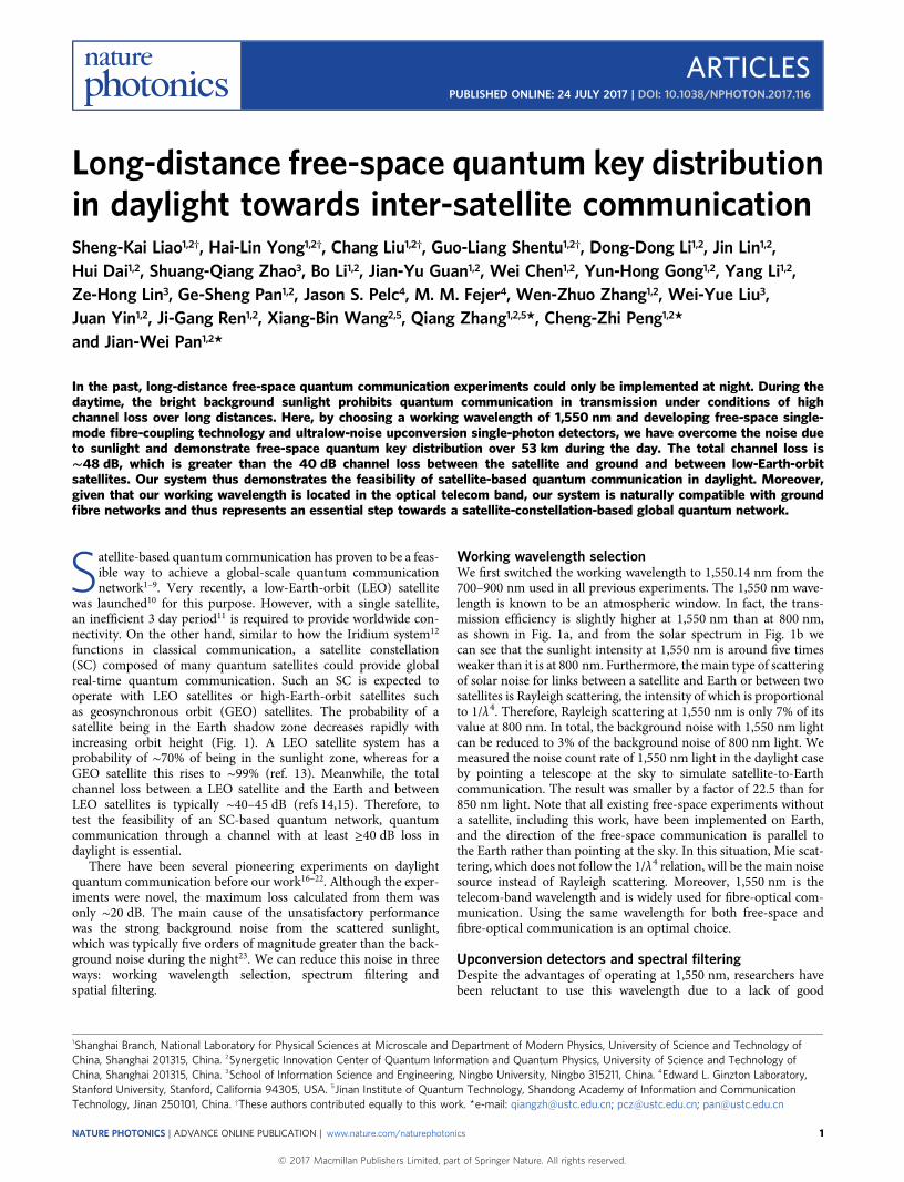
Field test across Qinghai LakeFigure 2 presents the set-up of our experiment on Qinghai Lake. Wechose Qinghai Lake because it has a good visual point of view(length of 53 km). The sending terminal (Alice) was located atHeimahe village (N36°49′01.3′′, E99°44′51.3′′), Qinghai Province,China (Fig. 2a). Alice sent the 1,550 nm signal beam through a53 km free-space link across Qinghai Lake to the receiving terminal(Bob),whichwas located atQuanji village (N37°16′42.4′′, E99°52′59.9′′),Qinghai Province.
At the sending terminal we developed a 1,550 nm light sourcewith a decoy scheme26–28. We used four DFB lasers with a centralwavelength at 1,550.14 nm and FWHM of 0.02 nm to emit 500 pspulses. We created a standard BB84 source by combining thepulses with two polarizing beamsplitters (PBSs), one beamsplitter(BS) and one variable optical attenuator. At a clock frequency of100 MHz, the source randomly generates one of four polarizationstates, |H⟩, |V⟩, |+⟩ and |–⟩, with one of three average photonnumbers per pulse (0.6, 0.14, 0). Here |H⟩/|V⟩ representshorizontal and vertical polarization, |+⟩ = (|H⟩ + |V⟩)/ ��
2√
and|−⟩ = (|H⟩ − |V⟩)/ ��
2√
. The intensity of the signal state was 0.6 perpulse. We used two decoy states: the vacuum state and a state withaverage photon number 0.14. The probability ratio of the signaland the two decoy states was 2:1:1. All random control signals weregenerated at high speed by a random number generator. The signalwas then coupled into the SMF and collimated out into free spacewith a triplet collimator (TC) and then sent to the telescope
(mounted on a two-dimensional platform, Fig. 2b). We minimizedthe sending divergence angle of the 1,550 nm beam to reducegeometric loss. We chose a Schmidt–Cassegrain system with a d =254 mm primary mirror for sending, because the divergence angleis proportional to the wavelength and inversely proportional to thesize of the primary mirror. The measured divergence angle was12 μrad, which is very close to the diffraction limit and four timessmaller than our previous sending system6.
At the receiving terminal, the signal light was collected by areceiving telescope (Fig. 2c), which consisted of a primary parabolicmirror with a diameter of 420 mm and focal length of 2,000 mmand a SMF coupling module with an optical tracking system (seeMethods). The signal photons went through a 20-m-long SMF tothe detection system. A fibre BS was used to select a measurementbasis, and two fibre PBSs together with four upconversion SPDswere used for detection (Fig. 2d). All detected signals were sentinto a time-to-digital converter (TDC) for analysis. The timewindow was set to 1 ns, for timely filtering of the noise as in pre-vious experiments17,19. We also developed an efficient self-synchron-ized system based only on GPS, which could use fewer resourcesthan previous pulsed-laser synchronization systems4.
In our QKD experiment, Alice and Bob extracted the finalsecure key out of the raw data following a standard decoy BB84post-processing procedure27–29. The final key rate formula is
Rpulse ≥ qpμ{−Qμ f (Eμ)H2(Eμ) + Q1[1− H2(e1)]} (1)
20 m
671 nm
810 nmLD: 1,550.14 nm
1,548 nm
BSPBS
PBS
H V+ −
532 nm
CCD
BSFSM
CMOS
OSA
TCWDM
BSIFLens
TC
a
850 nm
PBS
PBS
PumpInput
OSA
Lens
PPLN IF Lens
VBG
eBSWDM
DM CMOSFSM
c
b
a
e
d
N
Fibre53 km
10 km
QINGHAI LAKE
Detector
Figure 2 | Birds-eye view of the 53 km QKD experiment in daylight. Alice and Bob are located on either side of Qinghai Lake. a, The 1,550 nm laser diodes(LDs) are encoded to four quantum states (|H⟩,|V⟩,|+⟩,|–⟩) by two polarizing beamsplitters (PBSs) and one beamsplitter (BS). An 810 nm beacon laser and a1,548 nm reference laser are combined and sent to a triplet collimator (TC) for optical alignment and tracking. An optical spectrum analyser (OSA) is usedto calibrate the signal spectrum. WDM, wavelength division multiplexer. b, The sending terminal has a telescope system on a two-axis rotation stage and anoptical tracking system. CCD, charge-coupled device; FSM, fast-steering mirror; IF, interference filter. c, The receiving terminal has an off-axial parabolicmirror and a SMF coupling module. d, Received photons are transmitted to the detector via a 20 m fibre. At the detection part, photons are measured withtwo PBSs, one BS and four detectors. e, Upconversion single-photon detector modules. A narrow-bandwidth volume Bragg grating (VBG) is used to narrowthe working spectrum of the detectors and reduce the noise. For details of optical alignment and tracking, see Methods. PPLN, periodically poled lithiumniobate. Map data: Google, CNES/Airbus, Digital Globe, Landsat/Copernicus.
NATURE PHOTONICS DOI: 10.1038/NPHOTON.2017.116 ARTICLES
NATURE PHOTONICS | ADVANCE ONLINE PUBLICATION | www.nature.com/naturephotonics 3
© 2017 Macmillan Publishers Limited, part of Springer Nature. All rights reserved.

where q = 1/2 is the basis reconciliation factor, pμ is the probabilityof emitting signal states, Qμ and Eμ are the gain and error rate of thesignal states, respectively, and f is the error correction efficiency. Thelow-density parity-check (LDPC) code was used for error correc-tion, with H2(e) = –elog2(e) – (1 – e)log2(1 – e) being the binaryShannon entropy function and Q1 (e1) the gain (phase error rate)when the source generates single-photon states. We carried outand repeated QKD experiments from 15:30 to 17:00 local time forseveral sunny days. Three typical groups of results are listed inTable 1. We obtained 157,179 bits during 1,756 s effective time.The final key rate was 20–400 bits per second. The variation ofthe final key rate was mainly due to channel loss changes in theatmospheric environment.
All the data were collected in good weather, as was the case forthe long-distance QKD experiments in refs 2–4 and 6.Unfortunately, implementing quantum communication in badweather is not possible with current technology. However, we notethat there will be no turbulence or bad weather between satellites.Only when considering quantum communication between a satel-lite and the ground must bad weather be taken into account.
The internal modulation of the decoy/signal states guaranteedour system security against photon number splitting30,31 and unam-biguous-state-discrimination attack32. The total loss over our 53 kmfree-space QKD was 48 dB, which consisted of a 14 dB SMFcoupling loss and 34 dB other loss (including geometric loss, airattenuation, receiving loss and detection loss). Our experimentshowed the success of QKD through a 48 dB loss channel, whichoffers strong support for an SC-based quantum network.
In our experiment, both the sender and receiver are fixed and, ingeneral, a full simulation of SC quantum communication shouldinclude a fast-moving party. However, in our previous study6 wedeveloped high-precision acquisition, tracking and pointing (ATP)technology and implement QKD with a fast-moving platform.Also, SMF coupling technology for LEO–ground33 and GEO–ground34 have been well verified. We believe that with the ATPtechnology developed in previous experiments, our work providessolid proof of SC-based quantum communication.
ConclusionWe have successfully demonstrated free-space QKD over 53 km indaylight. With a working wavelength of 1,550 nm, upconversionSPD and SMF coupling, we offer a solution to the problem ofquantum communication in daylight. Our work proves the feasi-bility of a LEO quantum SC that works predominantly in daylight.Moreover, our work also offers an optimal option for a globalquantum network consisting of a quantum SC and existingground fibre networks. Our free-space single-mode coupling tech-nology is also very useful for both free-space quantum communi-cation and laser communication applications such as QKD withimperfect devices35,36, quantum teleportation37, quantum repeaters38
and quantum metrology39,40. Moreover, the SC-based quantumnetwork can also find rapid application in precisely sharingtiming information globally41.
The communication distance and secure key rate still have roomfor improvement. The system repetition rate can be improved byincreasing the upconversion detector rate, which may become aslarge as 2 GHz (ref. 42). With cavity-enhanced SAPD, we can
increase the efficiency of the upconversion detector to improvethe secure key rate. Meanwhile, superconducting SPDs (SSPDs)have a higher detection efficiency and lower intrinsic dark countthan upconversion SPDs. In our experiment, because of thelimited space and tough environment in the container, we chosean upconversion SPD for its compact size and room-temperatureoperation. With future miniaturization of SSPDs, we can definitelyimprove the performance of the entire system. Moreover, for futuresatellite-to-ground communication with a very small zenith angle,Rayleigh scattering will dominate and we could have an evenbetter SNR than in our ground experiment with 1,550 nm light.
Recently, a novel experiment34 has been carried out that implementsquantum state transfer from a GEO satellite to the ground and showsthe potential of continuous variable QKD in daylight. Overall, com-pared with discrete-variable QKD, for example using a homodynedetector, continuous-variable QKD ismore robust against backgroundnoise in daylight, but suffers from high channel losses43,44.
MethodsMethods and any associated references are available in the onlineversion of the paper.
Received 1 March 2017; accepted 8 June 2017;published online 24 July 2017
References1. Peng, C.-Z. et al. Experimental free-space distribution of entangled photon pairs
over 13 km: towards satellite-based global quantum communication. Phys. Rev.Lett. 94, 150501 (2005).
2. Schmitt-Manderbach, T. et al. Experimental demonstration of free-space decoy-state quantum key distribution over 144 km. Phys. Rev. Lett. 98, 010504 (2007).
3. Jin, X.-M. et al. Experimental free-space quantum teleportation. Nat. Photon. 4,376–381 (2010).
4. Yin, J. et al. Quantum teleportation and entanglement distribution over100-kilometre free-space channels. Nature 488, 185–188 (2012).
5. Ma, X.-S. et al. Quantum teleportation over 143 kilometres using activefeed-forward. Nature 489, 269–273 (2012).
6. Wang, J.-Y. et al. Direct and full-scale experimental verifications towardsground-satellite quantum key distribution. Nat. Photon. 7, 387–393 (2013).
7. Nauerth, S. et al. Air-to-ground quantum communication. Nat. Photon. 7,382–386 (2013).
8. Yin, J. et al. Experimental quasi-single-photon transmission from satellite toearth. Opt. Express 21, 20032–20040 (2013).
9. Vallone, G. et al. Experimental satellite quantum communications. Phys. Rev.Lett. 115, 040502 (2015).
10. Xin, H. Chinese academy takes space under its wing. Science 332,904–904 (2011).
11. Fritz, L. W. Commercial Earth observation satellites. Int. Arch. Photogramm.Remote Sens. 31, 273–282 (1996).
12. Pratt, S. R., Raines, R., Fossa C. E. Jr & Temple, M. An operational andperformance overview of the Iridium Low Earth Orbit satellite system.IEEE Commun. Surv. 2, 2–10 (1999).
13. Gilmore, D. G. Spacecraft Thermal Control Handbook: FundamentalTechnologies Vol. 1 (American Institute of Aeronautics and Astronautics, 2002).
14. Pfennigbauer, M., Leeb, W., Aspelmeyer, M., Jennewein, T. & Zeilinger, A.Free-Space Optical Quantum Key Distribution Using Intersatellite Links(CNES–Intersatellite Link Workshop, 2003).
15. Tomaello, A., Dall’Arche, A., Naletto, G. & Villoresi, P. Intersatellite quantumcommunication feasibility study. Proc. SPIE 8163, 816309 (2011).
16. Buttler, W. T. et al. Daylight quantum key distribution over 1.6 km. Phys. Rev.Lett. 84, 5652–5655 (2000).
17. Hughes, R. J., Nordholt, J. E., Derkacs, D. & Peterson, C. G. Practical free-spacequantum key distribution over 10 km in daylight and at night. New J. Phys.4, 43 (2002).
Table 1 | Experimental parameters and results.
T (s) Qμ Qv Y0 Eμ (%) Ev (%) Rpulse Rtotal (bits)643 1.36 × 10⁻⁵ 3.99 × 10⁻⁶ 7.24 × 10⁻⁷ 3.19 9.18 9.42 × 10⁻⁷ 60,567649 9.12 × 10⁻⁶ 2.59 × 10⁻⁶ 3.02 × 10⁻⁷ 3.24 9.49 4.27 × 10⁻⁷ 27,700464 1.63 × 10⁻⁵ 4.11 × 10⁻⁶ 2.38 × 10⁻⁷ 1.65 3.35 1.49 × 10⁻⁶ 68,912
T is the effective time for QKD.Qμ andQv are the gains for the signal states and decoy states, respectively. Y0 is the yield for vacuum states. Eμ and Ev are the quantum bit error rate (QBER) of the signal states anddecoy states, respectively. Rpulse is final key rate per clock cycle and Rtotal is the total final key size of the experiment.
ARTICLES NATURE PHOTONICS DOI: 10.1038/NPHOTON.2017.116
NATURE PHOTONICS | ADVANCE ONLINE PUBLICATION | www.nature.com/naturephotonics4
© 2017 Macmillan Publishers Limited, part of Springer Nature. All rights reserved.

18. Höckel, D., Koch, L., Martin, E. & Benson, O. Ultranarrow bandwidth spectralfiltering for long-range free-space quantum key distribution at daytime.Opt. Lett. 34, 3169–3171 (2009).
19. Restelli, A. et al. Improved timing resolution single-photon detectors in daytimefree-space quantum key distribution with 1.25 GHz transmission rate. IEEE J.Sel. Top. Quantum Electron. 16, 1084–1090 (2010).
20. Shan, X., Sun, X., Luo, J., Tan, Z. & Zhan, M. Free-space quantum keydistribution with Rb vapor filters. Appl. Phys. Lett. 89, 191121 (2006).
21. Rogers, D. et al. Free-space quantum cryptography in the H-alpha Fraunhoferwindow. Proc. SPIE 6304, 630417 (2006).
22. Peloso, M. P., Gerhardt, I., Ho, C., Lamas-Linares, A. & Kurtsiefer, C. Daylightoperation of a free space, entanglement-based quantum key distribution system.New J. Phys. 11, 045007 (2009).
23. Miao, E.-L. et al. Background noise of satellite-to-ground quantum keydistribution. New J. Phys. 7, 215 (2005).
24. Shentu, G.-L. et al. Ultralow noise up-conversion detector and spectrometer forthe telecom band. Opt. Express 21, 13986–13991 (2013).
25. Ren, J.-G. et al. Long-distance quantum teleportation assisted with free-spaceentanglement distribution. Chin. Phys. B 18, 3605 (2009).
26. Hwang, W.-Y. Quantum key distribution with high loss: toward global securecommunication. Phys. Rev. Lett. 91, 057901 (2003).
27. Wang, X.-B. Beating the photon-number-splitting attack in practical quantumcryptography. Phys. Rev. Lett. 94, 230503 (2005).
28. Lo, H.-K., Ma, X. & Chen, K. Decoy state quantum key distribution. Phys. Rev.Lett. 94, 230504 (2005).
29. Fung, C.-H. F., Ma, X. & Chau, H. F. Practical issues in quantum-key-distribution postprocessing. Phys. Rev. A 81, 012318 (2010).
30. Huttner, B., Imoto, N., Gisin, N. & Mor, T. Quantum cryptography withcoherent states. Phys. Rev. A 51, 1863–1869 (1995).
31. Brassard, G., Lütkenhaus, N., Mor, T. & Sanders, B. C. Limitations on practicalquantum cryptography. Phys. Rev. Lett. 85, 1330–1333 (2000).
32. Lo, H.-K. & Preskill, J. Security of quantum key distribution using weakcoherent states with nonrandom phases. Quantum Inform. Comput. 7,431–458 (2007).
33. Takenaka, H., Toyoshima, M. & Takayama, Y. Experimental verification offiber-coupling efficiency for satellite-to-ground atmospheric laser downlinks.Opt. Express 20, 15301–15308 (2012).
34. Günthner, K. et al. Quantum-limited measurements of optical signals from ageostationary satellite. Optica 4, 611–616 (2017).
35. Lo, H.-K., Curty, M. & Qi, B. Measurement-device-independent quantum keydistribution. Phys. Rev. Lett. 108, 130503 (2012).
36. Braunstein, S. L. & Pirandola, S. Side-channel-free quantum key distribution.Phys. Rev. Lett. 108, 130502 (2012).
37. Bennett, C. H. et al. Teleporting an unknown quantum state via dual classicaland Einstein–Podolsky–Rosen channels. Phys. Rev. Lett. 70, 1895–1899 (1993).
38. Briegel, H.-J., Dür, W., Cirac, J. I. & Zoller, P. Quantum repeaters: the role ofimperfect local operations in quantum communication. Phys. Rev. Lett. 81,5932–5935 (1998).
39. Giovannetti, V., Lloyd, S. & Maccone, L. Quantum-enhanced measurements:beating the standard quantum limit. Science 306, 1330–1336 (2004).
40. Yurke, B. Wideband photon counting and homodyne detection. Phys. Rev. A 32,311–323 (1985).
41. Komar, P. et al. A quantum network of clocks. Nat. Phys. 10, 582–587 (2014).42. Thew, R. T. et al. Low jitter up-conversion detectors for telecom wavelength GHz
QKD. New J. Phys. 8, 32 (2006).43. Leverrier, A. Composable security proof for continuous-variable quantum key
distribution with coherent states. Phys. Rev. Lett. 114, 070501 (2015).44. Jouguet, P. et al. Experimental demonstration of long-distance continuous-
variable quantum key distribution. Nat. Photon. 7, 378–381 (2013).
AcknowledgementsThe authors thank Y.-A. Chen, Y. Cao, Y. Liu and Y. Xu for discussions. This work wassupported by the National Fundamental Research Program (grant no. 2013CB336800), the‘Strategic Priority Research Program’ of the Chinese Academy of Sciences (grant no.XDA04030000), the National Natural Science Foundation of China, the Chinese Academyof Sciences and the 10000-Plan of Shandong Province (Taishan Scholars).
Author contributionsQ.Z., C.-Z.P. and J.-W.P. conceived and designed the experiment. S.-K.L., J.L., W.C., Y.L.,Z.-H.L., C.-Z.P. and J.-W.P. designed QKD devices. H.-L.Y., C.L., D.-D.L., B.L., H.D.,Y.-H.G., J.-G.R., C.-Z.P. and J.-W.P. developed the SMF coupling technique. G.-L.S.,J.-Y.G., J.S.P., M.M.F. and Q.Z. implemented upconversion detectors. S.-K.L., H.-L.Y.,S.-Q.Z. and W.-Y.L. designed software. X.-B.W. contributed to the decoy-state analysis.Q.Z., C.-Z.P. and J.-W.P. analysed the data and wrote the manuscript, with input fromS.-K.L., H.-L.Y. andC.L. All authors contributed to the data collection, discussed the results,and reviewed the manuscript. C.-Z.P. and J.-W.P. supervised the whole project.
Additional informationSupplementary information is available in the online version of the paper. Reprints andpermissions information is available online at www.nature.com/reprints. Publisher’s note:Springer Nature remains neutral with regard to jurisdictional claims in published maps andinstitutional affiliations. Correspondence and requests for materials should be addressed toQ.Z., C.-Z.P. and J.-W.P.
Competing financial interestsThe authors declare no competing financial interests.
NATURE PHOTONICS DOI: 10.1038/NPHOTON.2017.116 ARTICLES
NATURE PHOTONICS | ADVANCE ONLINE PUBLICATION | www.nature.com/naturephotonics 5
© 2017 Macmillan Publishers Limited, part of Springer Nature. All rights reserved.

MethodsAlignment and calibration. A 500 mW, 532 nm beacon laser, coaxially located onthe sending telescope, was pointed at the receiving site. We manually aligned theparabolic mirror to make sure that the green laser spot was pointed at the mirror’scentre. A 2 W, 671 nm beacon laser, coaxially located on the receiving telescope, waspointed at the sending site. At the sending sites, a wide-field camera was installedbehind the guide scope to take photographs of the red beacon light. This informationwas fed to the two-dimensional sending platform, which aligned the telescope toachieve optimal tracking of the 671 nm beacon light. This arrangement formed thecoarse tracking system at the sending site. The fine tracking system consisted of a BS,an FSM, an interference filter (IF) and a complementary metal oxide semiconductor(CMOS) imaging sensor (Fig. 2). The BS was used to collect the 671 nm beacon lightfor fine tracking of the CMOS sensor, while the FSM was used to finely adjust theoptical path according to a correction program using image information obtained bythe fine-tracking CMOS imaging sensor.
At the sending site, as well as the 532 nm laser, we also used two additionallasers. One was a 10 mW, 810 nm beacon laser and the other a 1 W, 1,548 nmreference laser. The two lasers were mixed with signal light with a WDM and a BS,respectively (Fig. 2), and were used as beacon lights to align and track SMF coupling.At the receiving site, the SMF coupling system, mounted on a one-dimensionaltranslation stage, consisted of an FSM, a DM and a CMOS. The FSM was just thesecondary mirror of the receiving telescope, and the DM reflected telecom-bandlight and transmitted the 810 nm beacon light. The reflected telecom-band light wascollimated into the SMF and the transmitted 810 nm light was captured by theCMOS imaging sensor. Before the QKD experiment, we combined a 810 nm laserand a 1,548 nm laser into a 3 m free-space collimator and shone the light to thereceiving telescope to simulate the beacon light. With the simulated light, we firstlocated the SMF in the focal point of the parabolic reflector by adjusting thetranslation stage, then aligned the FSM and DM to optimize the fibre couplingefficiency. Once the maximum efficiency was achieved, we recorded and marked the810 nm light position by the CMOS sensor. During the QKD experiment, we first
made sure that the 810 nm beacon light was located at the marked position of theCMOS imaging sensor, then we optimized the translation stage, the FSM and theDM by measuring the coupled optical power of the SMF with an InGaAs powermeter. Meanwhile, a 850 nm beacon laser was also coupled into the fibre at thereceiver side, working as a fine beacon for the transmitter.
In our experiment, the shift of the bandwidth of our lasers and detectors shouldbe guaranteed. We used a high-precision optical spectrum analyser (OSA) at thesource and detector. The OSA in Fig. 2a was for the source, and another was locatedat the input (Fig. 2e). The OSAs were self-calibrated in advance. After the link wasestablished, a strong light (∼1 W optical power) at 1,548 nm was sent from thetransmitter to the receiver. With OSAs, the wavelength was precisely measured at thetwo terminals. The wavelength for the source and detector was calibrated with aprecision smaller than 0.01 nm.
We adapted several lasers with different wavelengths (532, 671, 810, 850, 1,570,1,548 and 1,550.14 nm) for various applications. The 1,550.14 nm wavelength is thewavelength for QKD. The 532, 671, 810 and 850 nm lasers are for coarse alignment,1,548 nm for fine alignment and wavelength reference, and 1,570 nm for monitoringthe link stability and channel losses. We needed to make sure that chromaticdispersion does not influence the system’s performance. The 532 and 671 nm laserswere parallel to the optical link for the QKD and did not share the same optics as thesignal, and the chromatic dispersion for them in the 53 km of air was negligible. Thechromatic dispersion for the 1,548, 1,550.14 and 1,570 nm lasers was also negligibledue to their small wavelength differences in relation to the QKD signal wavelength.So, only the 810 and 850 nm lasers were of concern. We used reflection opticsinstead of transmission optics as much as possible, as this can reduce chromaticdispersion. Moreover, the divergence angle for 810 and 850 nm was several timeslarger than the diffraction limit. In that sense, dispersion was not a problem forcoarse alignment.
Data availability. The data that support the plots within this paper and other findingsof this study are available from the corresponding authors upon reasonable request.
ARTICLES NATURE PHOTONICS DOI: 10.1038/NPHOTON.2017.116
NATURE PHOTONICS | www.nature.com/naturephotonics
© 2017 Macmillan Publishers Limited, part of Springer Nature. All rights reserved.