Embed Size (px)
Citation preview


Thank you for purchasing MD100P LONWORKS Option Board.
SAFETY PRECAUTIONS
Always follow safety instructions to prevent accidents and potential hazards from occurring.
Safety precautions are classified into “WARNING” and “CAUTION” and their meanings are as follows:
WARNING
CAUTION
The indicated illustrations on the product and in the manual have the following meanings.
Danger may be present. Read the message and follow the instructions carefully.
Particular attention should be paid because danger of an electric shock may be present.
Keep operating instructions handy for quick reference.
Read the operating instructions carefully to fully understand the functions of the MDLV-100P series and to use it
properly.
CAUTION
Be cautious, when handling the CMOS components of the Option Board.
Static may lead to malfunctioning of the product.
Turn off the inverter power, when changing the communication cable.
Otherwise, you may damage the board or a communication error may occur.
Make sure to insert the Option Board connector to the inverter precisely.
Otherwise, you may damage the board or a communication error may occur.
Check the parameter unit before setting up the parameter.
Otherwise, a communication error may occur.
Improper operation may result in serious personal injury or
death.
Improper operation may result in slight to medium personal
injury or property damage.

MD100P LONWORKS Manual
1
1. Introduction
LONWORKS technology was born in Echelon Co. LONWORKS Network is generally used for factory or building automation.
There is no Master/Slave concept in the LONWORKS network but all the nodes (devices) communicate with each other
through LONTalk protocol. And LONWORKS nodes don’t have dependence on other manufacturers. The independence is only
available by using Standard Network Variable Type (SNVT), which is provided by LONWORKS. The 100P LONWORKS
communication card also supports the Standard Network Variable type variables.
All network variables have input and output variables. Data communication will automatically get started when you connect the
input and output variables with the Installation Tool. To connect input variables with output variables, their types of the network
should be identical.
2. Technical features of LONWORKS
Protocol LonTalk
LONWORKS Com. Chip FT3150-P20 chip from Echelon
LONWORKS transceiver FT-X1
Data types Peer-to-peer communication
LONWORKS connector Pluggable connector
Channel Type TP/FT-10
Transfer cable Free Topology Twisted Pair
Baud rate 78 Kbit/s
Topology Free Topology (Bus, Star, Loop, or compound of the previous)

MD100P LONWORKS Manual
2
3. Guidelines to install
Refer to the Quick Guide below to install 100P LONWORKS communication card.
1) Open the package of the 100P LONWORKS and check the communication card for external damages.
2) Verify the function of 100P with the power connected whether the functions operate well or not. And check inverter
operation by operating keypad.
3) Turn the power of 100P off and wait at least 5 minutes until the voltage of the inverter gets discharged. Check if the
voltage level is in a safe range by measuring the DC link voltage.
4) Install the 100P LONWORKS communication card to an 100P inverter.
4-1) Uncover the 100P inverter and mount the 100P LONWORKS communication card
4-2) Connect communication cable (A, B). Connect the cable not considering polarity, for LONWORKS
communication cable has no polarity.
4-3) If the node is located at the end of the network, use the terminal resistance selection switch to set the terminal.
5) Download an external interface file (lonCerusVFD.xif) and the appropriate resource file (lonCerusVFD.apb or
lonCerusVFD.nxe) for use by your Network Tool. You can download the files from our homepage
http://www.cerusind.com
6) Turn on the power of inverter and verify COM-01 Opt B/D with the 100P keypad whether it is automatically set to
LonWorks or not.
7) Set the related parameters for LonWorks communication on the inverter.
8) Examine LED status of the 100P LONWORKS communication card. SERVICE LED will blink by 0.5Hz if you didn’t
configure the card.
9) Wait at least 5 minutes after the 100P is turned off to discharge DC Link voltage. It is the end of the installation, cover up
the lid of the inverter.
Cf.) You must set up the configuration before you try to communicate by LONWORKS communication. It is not available
to communicate with LONWORKS communication without the configuration.
10) Turn on the 100P again and turn the SVC switch on and off to configure the communication.
11) When the configuration is finished successfully, the SERVICE LED will be turned off.

MD100P LONWORKS Manual
3
4. Network connection
100P LONWORKS communication card offers a pluggable connector.
This table describes about the connector. LONWORKS communication cable should be connected to No. 1 and 2 of the
connector. You may connect the cable without considering polarity because LONWORKS communication has no polarity.
5. Network Termination
Set up the terminal to guarantee the reliability of communication data.
You may set up the terminal of communication cards at both ends (BUS Topology) or a communication card at one side (Free Topology).
100P LONWORKS communication card contains a terminal resistance. You may determine whether you will use a terminal
resistance by DIP switch in the 100P LONWORKS communication card. Set up one or two terminal resistances according to
network topology. Free Topology uses 500Ω resistance. And there is one LONWORKS device that is terminated with a
resistance in the network. In case of Bus Topology, it has 100Ω as a terminal resistance and two LONWORKS devices.
This table describes terminal types according to the location of the switch.
Switch location Terminal type
FT
Free Topology
50Ω terminal resistance
Set up one terminal for LONWORKS communication card of the network
NO No use of terminal resistance
BUS
Bus Topology
105Ω terminal resistance
Set up two terminals for LONWORKS communication card of the network.
Terminal types of network topologies
Switch location Terminal type
1 A Network cable connection (No polarity)
2 B
3 S Shield connection

MD100P LONWORKS Manual
4
Terminal switch configurations of 100P LONWORKS communication card
6. Network cable
Belden 85102, unshielded
Belden 8471, unshielded
Level IV 22AWG, unshielded
JY (St) Y 2x2x0.8, shielded
TIA568A Cat.5 24AWG
① Terminal resistance ③ Free Topology terminal ② BUS Topology terminal (100 Ω)
ON
1 2 3 4
ON
1 2 3 4
ON
1 2 3 4
MD100P LONWORKS Manual
5
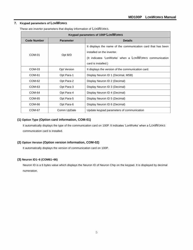
7. Keypad parameters of LONWORKS
These are inverter parameters that display information of LONWORKS.
(1) Option Type (Option card information, COM-01)
It automatically displays the type of the communication card on 100P. It indicates ‘LonWorks’ when a LONWORKS
communication card is installed.
(2) Option Version (Option version information, COM-02)
It automatically displays the version of communication card on 100P.
(3) Neuron ID1~6 (COM61~66)
Neuron ID is a 6 bytes value which displays the Neuron ID of Neuron Chip on the keypad. It is displayed by decimal
numeration.
Keypad parameters of 100P LONWORKS
Code Number Parameter Details
COM-01 Opt B/D
It displays the name of the communication card that has been
installed on the inverter.
(It indicates ‘LonWorks’ when a LONWORKS communication
card is installed.)
COM-03 Opt Version It displays the version of the communication card.
COM-61 Opt Para-1 Display Neuron ID 1 (Decimal, MSB)
COM-62 Opt Para-2 Display Neuron ID 2 (Decimal)
COM-63 Opt Para-3 Display Neuron ID 3 (Decimal)
COM-64 Opt Para-4 Display Neuron ID 4 (Decimal)
COM-65 Opt Para-5 Display Neuron ID 5 (Decimal)
COM-66 Opt Para-6 Display Neuron ID 6 (Decimal)
COM-67 Comm UpDate Update keypad parameters of communication
MD100P LONWORKS Manual
6
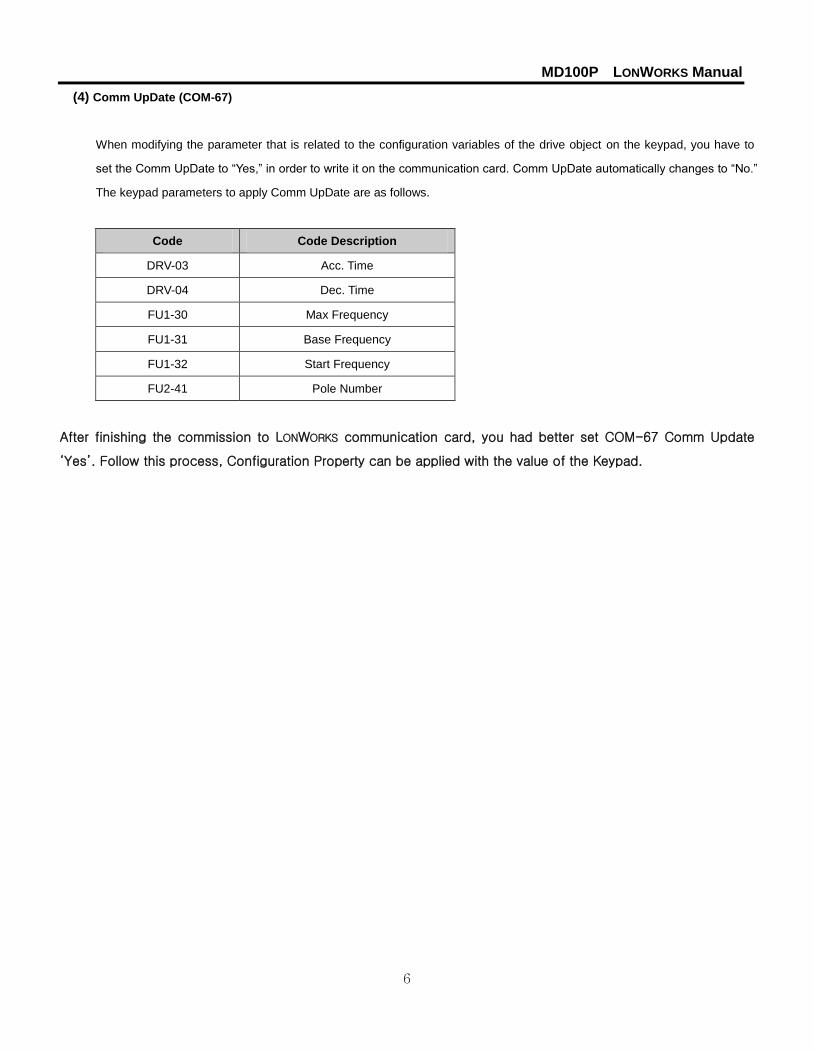
(4) Comm UpDate (COM-67)
When modifying the parameter that is related to the configuration variables of the drive object on the keypad, you have to
set the Comm UpDate to “Yes,” in order to write it on the communication card. Comm UpDate automatically changes to “No.”
The keypad parameters to apply Comm UpDate are as follows.
Code Code Description
DRV-03 Acc. Time
DRV-04 Dec. Time
FU1-30 Max Frequency
FU1-31 Base Frequency
FU1-32 Start Frequency
FU2-41 Pole Number
After finishing the commission to LONWORKS communication card, you had better set COM-67 Comm Update
‘Yes’. Follow this process, Configuration Property can be applied with the value of the Keypad.

MD100P LONWORKS Manual
7
8. Functional Profile
8.1 Node Object
8.1.1 Network Input Variables
Function Variable SNVT Type Min. value Max. value
Node Object Request nviRequest SNVT_obj_request - -
(1) nviRequest
The input, nviRequest is used to enable or update commands from network. This input supports RQ_ENABLE,
RQ_DISABLE, RQ_CLEAR_ALARM, RQ_NORMAL, RQ_CLEAR_STATUS, RQ_UPDATE_STATUS and
RQ_REPORT_MASK.
8.1.2 Network Output Variables
Function Variable SNVT Type Min. value Max. value
Node Object Status nvoStatus SNVT_obj_status - -
(1) nvoStatus
This nvoStatus reports node object status.
Invalid ID Invalid node ID requested
Report mask Reporting supported fields.
Disabled If RQ_DISABLE active
Electrical_fault Drive is faulted
Manual_control Drive is in local control
In_alarm Drive has an alarm
Node Object
Mandatory Network Variables
nviRequestSNVT_obj_requestnv1
nvoStatusSNVT_obj_statenv2
Input Network Variable
Output Network Variable

MD100P LONWORKS Manual
8
8.2 Drive Object
Mandatory Network Variables
nviDrvSpeedStptSNVT_switchnv1
nvoDrvSpeedSNVT_lev_percentnv4
Variable Speed Motor Drive (6010)
Optional Network Variables
nviDrvSpeedScaleSNVT_lev_percentnv2
nvoDrvCurrentSNVT_ampnv3
nvoDrvVoltSNVT_voltnv5
nvoDrvPwrSNVT_power_kilonv6
nvoDrvRunHoursSNVT_time_hournv7
nc17 nciLocation (Optional)nc50 nciMaxSpeed (Mandatory)nc53 nciMinSpeed (Mandatory)nc48 nciRcvHrtBt (Optional)nc49 nciSndHrtBt (Mandatory)nc52 nciMinOutTm (Optional)nc158 nciNmlSpeed (Mandatory)nc159 nciNmlFreq (Mandatory)nc160 nciRampUpTm (Mandatory)nc161 nciRampDownTm (Mandatory)nc162 nciDrvSpeedScale (Optional)
Configuration Properties
Input Network Variable
Output Network Variable

MD100P LONWORKS Manual
9
8.2.1 Network Input Variables
Function Variable SNVT Type Min. value Max. value
Drive Speed Setpoint nviDrivSpeedStpt SNVT_switch n/a n/a
Drive Speed Setpoint Scaling nviDrvSpeedScale SNVT_lev_percent 163.840% 163.840%
(1) nviDrvSpeedStpt
(2) nviDrvSpeedScale
▲ Definition
Network input SNVT_switch nviDrivSpeedStpt
Network input SNVT_lev_percent nviDrvSpeedScale
▲ Description
NviDrvSpeedStpt and nviDrvSpeedScale are used for the inverter run and speed command.
The state variable of nviDrvSpeedStpt is a value that decides the command to whether run or stop the inverter.
If the state of nviDrvSpeedStpt is 0, the inverter will stop and the inverter will run when the state value is 1.
nviDrvSpeedScale offers information of the operative direction. If a value of the nviDrvSpeedScale is positive, the motor runs
clockwise and if the nviDrvSpeedScale is negative, the motor runs counterclockwise.
Frequency command consists of a combination of nviDrvSpeedScale and nviDrvSpeedStpt. The value of both
nviDrvSpeedScale and nviDrvSpeedStpt are in % units and the multiplied value of the two is the input for the frequency
command of Base Freq. nviDrvSpeedScale provides the scale information of nviDrvSpeedStpt value. For example, if
nviDrvSpeedStpt is 100% and nviDrvSpeedScale is -80%, the actual speed is -80% (1 X 0.8 = 0.8). Therefore, the inverter
runs counterclockwise at a speed of the base frequency times 0.8. So, if the base frequency is 50.00 Hz, the frequency
command value would be 48Hz (50.00Hz X 0.8).
The input range for nviDrvSpeedScale is -163.840% ~ 163.830%. Therefore, if a value of 0x7fff(+163.835%) is put in, this
value would be a invalid data.
State and Value information of NviDrvSpeedStpt
State Value Run frequency / status of inverter
0 - Stop
1 0 0% frequency operation of the base frequency
1 0.5~100.0 0.5~100.0% frequency operation of the base frequency
1 100.0 100.0% frequency operation of the base frequency
0xFF - Auto

MD100P LONWORKS Manual
10
When you want to do the run or the frequency command with LONWORKS, you should set up the COM-02 Opt mode of the
COM group to “Cmd + Freq” by using the keypad. Set the COM-02 Opt mode to “Command” to operate the run command
only with LONWORKS and “Freq” is for the use of the frequency command.
Code Number/
Common area address Code Description Default Setting range
COM-02 Opt mode None
None
Command
Freq
Cmd + Freq
nviDrvSpeedScale Range -163.840% ~ 163.830%
nviDrvSpeedScale Default 0.000%
▲ Inverter parameters of NviDrvSpeedStpt, nviDrvSpeedScale
Code Number/
Common area address Code Description Default Setting range
0x0005 Frequency Command 0.00 Hz 0.00 ~ 120.00
0x0006 Run Command Refer to the description of common area
FU1-31 Base Frequency 50.00 Hz 30.00~120.00
Cf.) On network input variables, nviDrivSpeedStpt and nviDrvSpeedScale, you may use Lost Command by using the
nciRcvHrtBt variable.

MD100P LONWORKS Manual
11
8.2.2 Network Output Variables
Function Variable SNVT Type Min. value Max. value
Drive Speed Feedback nvoDrvSpeed SNVT_lev_percent 163.840% 163.840%
Actual Motor Current nvoDrvCurnt SNVT_amp 0.0A 3276.7A
Drive Output Voltage nvoDrvVolt SNVT_volt 0.0V 3276.7V
Actual Drive Power nvoDrvPwr SNVT_power_kilo 0.0kW 6553.5kW
Drive total running hours nvoDrvRunHours SNVT_time_hour 0h 65535h
(1) nvoDrvSpeed
▲ Definition
Network output SNVT_lev_percent nvoDrvSpeed
▲ Description
nvoDrvSpeed outputs the inverter’s current run speed by the percentage value of the base frequency. When the inverter
runs clockwise (counterclockwise), the value of the nvoDrvSpeed gets a positive (negative) value. For example, if the base
frequency is 50.00Hz and the inverter is running counterclockwise with 25.00Hz, novDrvSpeed outputs the value of -50.00%.
Typical Range -163.840 ~ 163.830 % (0.001 %)
▲ Inverter parameters for nvoDrvSpeed
Code Number/
Common area address Code Description Default Setting range
DRV-00
0x000A Output Frequency
-
0x000E Status of Inverter (FWD, REV)
FU1-31 Base Frequency 50.00 Hz 30.00~120.00
(2) nvoDrvCurnt
▲ Definition
Network output SNVT_amp nvoDrvCurnt
▲ Description
nvoDrvCurnt displays the output current value of the inverter by the unit of the A.
Typical Range 0.0 ~ 3276.6 A (0.1 A)

MD100P LONWORKS Manual
12
▲ Inverter parameters for nvoDrvCurnt
Code Number/
Common area address Code Description
DRV-08
0x0009 Current
(3) nvoDrvVolt
▲ Definition
Network output SNVT_volt nvoDrvVolt
▲ Description
nvoDrvVolt displays the output voltage value of the inverter by the unit of V.
Typical Range 0.0 ~ 700.0 V (0.1 V)
▲ Inverter parameters for nvoDrvVoltCurnt
Code Number/
Common area address Code Description
DRV-11
0x000B Output voltage
(4) nvoDrvPwr
▲ Definition
Network output SNVT_power_kilo nvoDrvPwr
▲ Description
nvoDrvPwr, the value of a network output variable, displays the output power of the inverter by the unit of kW.
Typical Range 0.0 ~ 6553.4 kW (0.1 kW)
▲ Inverter parameters for nvoDrvPwr
Code Number/
Common area address Code Description
MAK-01
0x0001 Capacity of the inverter

MD100P LONWORKS Manual
13
(5) nvoDrvRunHours
▲ Definition
Network output SNVT_time_hour nvoDrvRunHours
▲ Description
It displays the whole operation time of the inverter.
▲ Inverter parameters for nvoDrvPwr
Code Number/
Common area address Code Description
FU2-85 Whole operation time

MD100P LONWORKS Manual
14
8.2.3 Network Configuration Variable
Function Variable Optional/
Mandatory SNVT Type
Location Lable nciLocation Optional SCPTlocation
Maximum Motor Speed nciMaxSpeed Mandatory SCPTmaxSetpoint
Minimum Motor Speed nciMinSpeed Mandatory SCPTminSetpoint
Receive Heartbeat Time nciRcvHrtBt Optional SCPTmaxRcvTime
Send Heartbeat Time nciSndHrtBt Mandatory SCPTmaxSndTime
Minimum Send Time nciMinOutTm Optional SCPTMinOutTime
Nominal Motor Speed in RPM nciNmlSpeed Mandatory SCPTnomRPM
Nominal Motor Frequency nciNmlFreq Mandatory SCPTnomFreq
Minimum Ramp Up Time nciRampUpTm Mandatory SCPTrampUPTm
Minimum Ramp Down Time nciRampDownTm Mandatory SCPTrampDownTm
Default Value for nviDrvSpeedScale nciDrvSpeedScale Optional SCPTdefScale
Cf.) When you modify the parameter that is related to the configuration variable and set Comm UpDate parameter to ‘Yes’,
the modified value gets written to the configuration variable.
Code Number/
Common area address Code Description Default Setting range
COM-67 Comm UpDate No No
Yes
(1) Location Label (Optional)
▲ Definition
Network config input SNVT_str_asc nciLocation
▲ Description
nciLocation uses 6bytes Location string of Neuron Chip and saves the information of the physical location into nciLocation.
Default Empty spaces
(2) Maximum Motor Speed (Mandatory)
▲ Definition
Network config input SNVT_lev_percent nciMaxSpeed

MD100P LONWORKS Manual
15
▲ Description
nciMaxSpeed is the value to set the max speed of the motor. nciMaxSpeed is inputted by the percentage of the nominal
frequency (nciNmlFreq) configuration value. For example, if nciNmlFreq is 50.0Hz and nciMaxSpeed is 120%, the maximum
frequency will be 60.0Hz (50.0 X 1.2). The value, 60.0Hz, is written in the FU1-30 Max Freq and it will be shown on the
keypad.
nciMaxSpeed value is not able to modify while the inverter runs. You should stop the inverter first then you can modify the
nciMaxSpeed value.
The initial value of the nciMaxSpeed is the percentage value of the FU1-30 Max Freq, which compares to the FU1-31 Base
Freq. Therefore, the initial value of the nciMaxSpeed will be 100.00%.
nciMaxSpeed must satisfy the formula below.
Typical Range 100.000 ~ 150.000 % (0.001%)
Default 100.000%
※ As shown above, FU1-30 Max Freq is changed by nciMaxSpeed(%) of nciMinFreq(nciMinSpeed). Since 40~120.00Hz is
the setting range for Max Freq, original setting value of Max Freq is preserved when nciNmlFreq has to change below 40Hz
(ex. nciNmlFreq 30Hz, nciMaxSpeed 100.00%).
▲ Inverter parameters for nciMaxSpeed
Code Number/
Common area address Code Description Default Setting range
FU1-31 Base Frequency 50.00 Hz 30.00 ~ 400.00
FU1-30 Max Frequency 50.00 Hz 30.00 ~ 400.00
※ When you input the FU1-30 Max Freq value and set Comm Update as ‘Yes’ to apply the nciMaxSpeed value and if the
FU1-30 Max Freq is more than 160% of the FU1-31 Base Freq, FU1-30 Max Freq value is changed to 100% of the Base
Freq. For example, if the Base Freq is 50.00 Hz, the Max Freq is 120.00 Hz, and Comm Update is ‘Yes’, then the Max Freq
will be automatically changed to 50.00 Hz.
840.163840.163 SpeedMaximumSpeedMinimum

MD100P LONWORKS Manual
16
(3) Minimum Motor Speed (Mandatory)
▲ Definition
Network config input SNVT_lev_percent nciMinSpeed
▲ Description
nciMinSpeed is the value to set the min speed of the motor. nciMinSpeed is inputted by the percentage of the nominal
frequency (nciNmlFreq) configuration value. For example, if nciNmlFreq is 50.0Hz and nciMinSpeed is 10%, the maximum
frequency will be 5.0Hz (50.0 X 0.1). The value, 5.00Hz, is written in the FU1-32 Start Freq and it will be shown on the
keypad.
nciMinSpeed value is not able to modify while the inverter runs. You should stop the inverter first and then modify the
nciMinSpeed value.
The initial value of the nciMinSpeed is the percentage value of the FU1-32 Start Freq, which compares to the FU1-31 Base
Freq. Therefore, the initial value of the nciMaxSpeed will be 0.8%.
nciMInSpeed must satisfy the formula below.
Typical Range 0.000 ~ 40.000 % (0.001 %)
Default 0.000%
※ As shown above, FU1-30 Max Freq is changed by nciMaxSpeed(%) of nciMinFreq(nciMinSpeed). Since 40~120.00
Hz is the setting range for Max Freq, original setting value of Max Freq is preserved when nciNmlFreq has to cha
nge below 40Hz (ex. nciNmlFreq 30Hz, nciMaxSpeed 100.00%).
▲ Inverter parameters for nciMaxSpeed
Code Number/
Common area address Code Description Default Setting range
FU1-31 Base Frequency 50.00 Hz 30.00 ~ 120.00
FU1-32 Start Frequency 0.50 Hz 0.01 ~ 10.00
840.163840.163 SpeedMaximumSpeedMinimum

MD100P LONWORKS Manual
17
(4) Receive Heart Beat Time (Optional)
▲ Definition
Network config input SNVT_time_sec nciRcvHrtBt
▲ Description
Decide the maximum update cycle time of the network input variables, nviDrvSpeedStpt and nviDrvSpdScale. If Update of
nviDrvSpeedStpt and nviDrvSpdScale does not occur during the nciRcvHrBt time, it recognizes it as a condition of the
communication command loss and starts to run as the mode in the communication command loss of IO-93.
If you want to run with the mode which is set in the communication command loss, you have to set the COM-02 Opt mode
as a value, not “None.” Furthermore, the IO-92 Lost Cmd mode has to be set as a value also.
Typical Range 0.0 ~ 120.0 sec (0.1 sec)
Invalid Data, when input value is 0xFFFF(6553.5 sec)
Default 0.0 sec (not using Receive Heart Beat function)
▲ Inverter parameters for nciRcvHrtBt
Code Number/
Common area address Code Description Default Setting range
IO-92 COM Lost Cmd None
None
FreeRun
Stop
COM-02 Opt mode None
None
Cmd
Freq
Cmd+Freq
Caution) When communicating with LONWORKS, communication loss time of the inverter, IO-93 COM Time Out value,
does not get applied.

MD100P LONWORKS Manual
18
(5) Send Heart Beat Time(Mandatory)
▲ Definition
Network config input SNVT_time_sec nciSndHrtBt
▲ Description
It determines the maximum output time of the network output variables, such as nvoDrvSpeed, nvoDrvCurnt, nvoDrvVolt,
nvoDrvPwr, and nvoDrvRunHours.
Typical Range 0.0 ~ 6553.4 sec
Invalid Data, when input value is 0xFFFF(6553.5 sec)
Default 0.0 sec (not using Send Heart Beat function)
(6) Minimum Out Time (Optional)
▲ Definition
Network config input SNVT_time_sec nciMinOUtTm
▲ Description
It decides the min. time that network variables, such as nvoDrvSpeed, nvoDrvCurnt, nvoDrvVolt, nvoDrvPwr, and
nvoDrvRunHours have to wait until they get sent through communication.
The network value does not change by every little variation but it sends out the changed value every nciMinOutTm time. It is
used to reduce network traffic.
Typical Range 0.0 ~ 6553.4 sec (0.1 sec)
Invalid Data, when input value is 0xFFFF(6553.5 sec)
Default 0.0 sec (not using Minimum Out Time function)

MD100P LONWORKS Manual
19
(7) Nominal Motor Speed in RPM (Mandatory)
▲ Definition
Network config input SNVT_freq_hz nciNmlSpeed
▲ Description
nciNmlSpeed sets up the Base Freq of inverter.
The initial value of nciNmlSpeed will become 1800.00 rpm because it is converted from FU1-31 Base Freq into rpm (Base
on 50Hz of the Base Freq and 4 Pole Number). When the nciNmlSpeed value is modified, the value of nciNmlSpeed, which
is converted from rpm into Hz is reflected in FU1-31 Base Freq.
The below is the formula to convert RPM into Hz. The inverter parameter, M2-10 Pole Num, means the pole number of the
motor. You should set it properly.
Valid Range 0 ~ 65534 rpm (1 rpm)
Default 1500 rpm
▲ Inverter parameters for nciNmlSpeed
Code Number/
Common area address Code Description Default Setting range
FU2-41
0X0017 Pole Number 4 2~48
FU1-31 Base Frequency 50.00 Hz 30.00 ~ 120.00
▲ Caution
nciNmlFreq is automatically changed when you modify nciNmlSpeed. For example, when nciNmlSpeed is 1500rpm,
nciNmlFreq is 50.0Hz, FU1-31 Base Frequency of Keypad parameter is 50.00Hz, and BAS-11 Pole Number is 4, and if you
change nciNmlFreq to 750rpm, then nciNmlFreq will be 25Hz(FU1-31 Base Frequency is rounded up) and FU1-31 Base
Frequency of Keypad parameter will be 25Hz.
DRV-19 Start Frequency and DRV-20 Max Frequency will be changed together when you modify nciNmlSpeed and
nciNmlFreq. Referring to the above example, if nciMaxSpeed is 100.000% and nciMinSpeend is 10.000%, DRV-19 Start
Frequency will become 5Hz and DRV-20 Max Frequency will be 5Hz.
polesmotor ofnumber the
120 Hz)Frequency( Base minuteper rotation ofnumber The

MD100P LONWORKS Manual
20
(8) Nominal Motor Frequency (Mandatory)
▲ Definition
Network config input SNVT_freq_hz nciNmlFreq
▲ Description
nciNmlFreq sets up the Base Freq of inverter. The nciNmlFreq is a indispensable value to set the minimum(nciMinSpeed)
and maximum(nciMaxSpeed) frequency of the motor. nciMinSpeed and nciMaxSpeed are percentage values of the
nciNmlFreq. The initial value of nciNmlFreq is 50.0Hz, which is same as FU1-31 Base Freq.
Valid Range 30.0~400.0 (0.1 Hz)
Default 50.0 Hz
▲ Inverter parameters for nciNmlFreq
Code Number/
Common area address Code Description Default Setting range
FU1-31 Base Frequency 50.00 Hz 30.00 ~ 120.00
(9) Minimum Ramp Up Time (Mandatory)
▲ Definition
Network config input SNVT_time_sec nciRampUpTm
▲ Description
nciRampUpTm sets up the acceleration time. DRV-01 Acc. Time value will be changed into nciRampUpTm when
nciRampUpTm is modified. The initial value of the nciRampUpTm is same as DRV-01 ACC. Time. Therefore, the initial value
is 20.0 sec.
Valid Range 0.0~600.0 sec (0.1 sec)
Default 20.0 sec
▲ Inverter parameters for nciRampUpTm
Code Number/
Common area address Code Description Default Setting range
0x0007/DRV-03 Acc. Time 20.0 sec 0.0 ~ 600.0
(10) Minimun Ramp Down Time (Mandatory)
▲ Definition
Network config input SNVT_time_sec nciRampDownTm

MD100P LONWORKS Manual
21
▲ Description
nciRampDownTm sets up the deceleration time. DRV-02 Dec. Time value will be changed into nciRampDownTm when
nciRampDownTm is modified.
The initial value of nciRampDownTm is same as DRV-02 Dcc.Time. Therefore, the initial value is 30.0 sec.
Valid Range 0.0 ~ 600.0 sec (0.1 sec)
Default 30.0 sec
▲ Inverter parameters for nciRampDownTm
Code Number/
Common area address Code Description Default Setting range
0x0008
DRV-04 Dec. Time 30.0 sec 0.0 ~ 600.0
(11) Default for nviDrvSpeedScale (Optional)
▲ Definition
Network config input SNVT_lev_percent nciDrvSpeedScale
▲ Description
nciDrvSpeedScale is applied to the initial value of the network output variable, nviDrvSpeedScale.
Valid Range -163.840 ~ 163.830 (0.005 %)
Default 0.000 %
Cf.) FU1-31 Base Freq, FU1-30 Max Freq, FU1-32 Start Freq, FU2-41 Pole Num, DRV-01 Acc Time, and DRV-02 Dec Time
are keypad parameters that are closely related to the configuration property variables of drive object, such as nciNmlFreq,
nciNmlSpeed, nciMaxSpeed, nciMinSpeed, nciRampUPTm, and nciRampDownTm.
To modify FU1-31 Base Freq, FU1-30 Max Freq, FU1-32 Start Freq, FU2-41 Pole Num, DRV-01 Acc Time, and DRV-02 Dec
Time and save them into the configuration property variables, such as nciNmlFreq, nciNmlSpeed, nciMaxSpeed,
nciMinSpeed, nciRampUPTm, and nciRampDownTm, turn off the inverter and turn it on again.
For example, if you change the keypad parameters as the table below, nciMaxSpeed is 120.000%, nciMinSpeed is 20.000%,
nciNmlSpeed is 15000 rpm, nciNmlFreq is 50.0 Hz, nciRampUpTm is 19.0 sec, and nciRampDownTm is 29.0 sec.

MD100P LONWORKS Manual
22
Code Parameter Value Code Parameter Value
DRV-01 Acc. Time 19.0 sec DRV-02 Dec. Time 29.0 sec
FU1-30 Max Freq 50.00 Hz FU1-31 Base Freq 49.99 Hz
FU1-32 Start Freq 10.00 Hz FU2-41 Pole Num 4
① nciNmlFreq is down to the first decimal place and FU1-31 Base Freq is down to the second
decimal place. Therefore, the nciNmlFreq is 45.7Hz, because it rounds off at the second decimal
place of FU1-31.
All the Base Freq used in the calculation uses nciNmlFreq to calculate.
The Max Freq value should not exceed 163.840% of the Base Freq. The maximum value of nciMaxSpeed is 163.840%.
%000.150(%)10045.68
68.52(%)100
BaseFreq
MaxFreq dnciMaxSpee ③
...)559544.8%(555.8(%)10045.68
3.91(%)100
BaseFreq
StartFreq dnciMinSpee ④
)4.1370(13704
120 45.68
ploesmotor ofnumber the
120 BaseFreq dnciNmlSpee ② rpm

MD100P LONWORKS Manual
23
8.3 User Object (User Function Profile Type)
Mandatory Network Variables
User Object(20001)
nvoUsrParaState1SNVT_countnv9
nvoUsrParaState2SNVT_countnv10
nvoUsrParaState3SNVT_countnv11
nvoUsrParaState4SNVT_countnv12
nvoUsrParaState5SNVT_countnv13
nvoUsrParaState6SNVT_countnv14
nvoUsrParaState7SNVT_countnv15
nvoUsrParaState8SNVT_countnv16
nviUsrParaCtrl1SNVT_countnv1
nviUsrParaCtrl2SNVT_countnv2
nviUsrParaCtrl3SNVT_countnv3
nviUsrParaCtrl4SNVT_countnv4
nviUsrParaCtrl5SNVT_countnv5
nviUsrParaCtrl6SNVT_countnv6
nviUsrParaCtrl7SNVT_countnv7
nviUsrParaCtrl8SNVT_countnv8
Input Network Variable
Output Network Variable
nc1 nciUsrRcvHrtBt (Optional)nc2 nciUsrSndHrtBt (Optional)nc3 nciUsrMinOutTm (Optional)
Configuration Properties
MD100P LONWORKS Manual
24
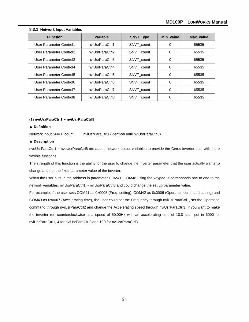
8.3.1 Network Input Variables
Function Variable SNVT Type Min. value Max. value
User Parameter Control1 nviUsrParaCtrl1 SNVT_count 0 65535
User Parameter Control2 nviUsrParaCtrl2 SNVT_count 0 65535
User Parameter Control3 nviUsrParaCtrl3 SNVT_count 0 65535
User Parameter Control4 nviUsrParaCtrl4 SNVT_count 0 65535
User Parameter Control5 nviUsrParaCtrl5 SNVT_count 0 65535
User Parameter Control6 nviUsrParaCtrl6 SNVT_count 0 65535
User Parameter Control7 nviUsrParaCtrl7 SNVT_count 0 65535
User Parameter Control8 nviUsrParaCtrl8 SNVT_count 0 65535
(1) nviUsrParaCtrl1 ~ nviUsrParaCtrl8
▲ Definition
Network input SNVT_count nviUsrParaCtrl1 (identical until nviUsrParaCtrl8)
▲ Description
nvoUsrParaCtrl1 ~ nvoUsrParaCtrl8 are added network output variables to provide the Cerus inverter user with more
flexible functions.
The strength of this function is the ability for the user to change the inverter parameter that the user actually wants to
change and not the fixed parameter value of the inverter.
When the user puts in the address in parameter COM41~COM48 using the keypad, it corresponds one to one to the
network variables, nviUsrParaCtrl1 ~ nviUsrParaCtrl8 and could change the set up parameter value.
For example, if the user sets COM41 as 0x0005 (Freq. setting), COM42 as 0x0006 (Operation command setting) and
COM43 as 0x0007 (Accelerating time), the user could set the Frequency through nviUsrParaCtrl1, set the Operation
command through nviUsrParaCtrl2 and change the Accelerating speed through nviUsrParaCtrl3. If you want to make
the inverter run counterclockwise at a speed of 50.00Hz with an accelerating time of 10.0 sec., put in 6000 for
nviUsrParaCtrl1, 4 for nviUsrParaCtrl2 and 100 for nviUsrParaCtrl3.
MD100P LONWORKS Manual
25
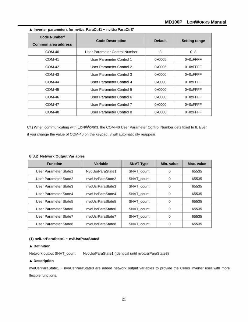
▲ Inverter parameters for nviUsrParaCtrl1 ~ nviUsrParaCtrl7
Code Number/
Common area address Code Description Default Setting range
COM-40 User Parameter Control Number 8 0~8
COM-41 User Parameter Control 1 0x0005 0~0xFFFF
COM-42 User Parameter Control 2 0x0006 0~0xFFFF
COM-43 User Parameter Control 3 0x0000 0~0xFFFF
COM-44 User Parameter Control 4 0x0000 0~0xFFFF
COM-45 User Parameter Control 5 0x0000 0~0xFFFF
COM-46 User Parameter Control 6 0x0000 0~0xFFFF
COM-47 User Parameter Control 7 0x0000 0~0xFFFF
COM-48 User Parameter Control 8 0x0000 0~0xFFFF
Cf.) When communicating with LONWORKS, the COM-40 User Parameter Control Number gets fixed to 8. Even
if you change the value of COM-40 on the keypad, 8 will automatically reappear.
8.3.2 Network Output Variables
Function Variable SNVT Type Min. value Max. value
User Parameter State1 NvoUsrParaState1 SNVT_count 0 65535
User Parameter State2 nvoUsrParaState2 SNVT_count 0 65535
User Parameter State3 nvoUsrParaState3 SNVT_count 0 65535
User Parameter State4 nvoUsrParaState4 SNVT_count 0 65535
User Parameter State5 nvoUsrParaState5 SNVT_count 0 65535
User Parameter State6 nvoUsrParaState6 SNVT_count 0 65535
User Parameter State7 nvoUsrParaState7 SNVT_count 0 65535
User Parameter State8 nvoUsrParaState8 SNVT_count 0 65535
(1) nviUsrParaState1 ~ nviUsrParaState8
▲ Definition
Network output SNVT_count NvoUsrParaState1 (identical until nvoUsrParaState8)
▲ Description
nvoUsrParaState1 ~ nvoUsrParaState8 are added network output variables to provide the Cerus inverter user with more
flexible functions.
MD100P LONWORKS Manual
26
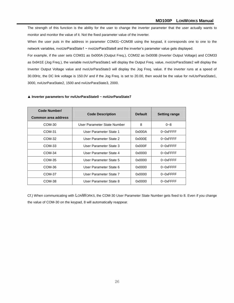
The strength of this function is the ability for the user to change the inverter parameter that the user actually wants to
monitor and monitor the value of it. Not the fixed parameter value of the inverter.
When the user puts in the address in parameter COM31~COM38 using the keypad, it corresponds one to one to the
network variables, nvoUsrParaState1 ~ nvoUsrParaState8 and the inverter’s parameter value gets displayed.
For example, if the user sets COM31 as 0x000A (Output Freq.), COM32 as 0x000B (Inverter Output Voltage) and COM33
as 0x941E (Jog Freq.), the variable nvoUsrParaState1 will display the Output Freq. value, nvoUsrParaState2 will display the
Inverter Output Voltage value and nvoUsrParaState3 will display the Jog Freq. value. If the inverter runs at a speed of
30.00Hz, the DC link voltage is 150.0V and if the Jog Freq. is set to 20.00, then would be the value for nviUsrParaState1,
3000, nviUsrParaState2, 1500 and nviUsrParaState3, 2000.
▲ Inverter parameters for nviUsrParaState0 ~ nviUsrParaState7
Code Number/
Common area address Code Description Default Setting range
COM-30 User Parameter State Number 8 0~8
COM-31 User Parameter State 1 0x000A 0~0xFFFF
COM-32 User Parameter State 2 0x000E 0~0xFFFF
COM-33 User Parameter State 3 0x000F 0~0xFFFF
COM-34 User Parameter State 4 0x0000 0~0xFFFF
COM-35 User Parameter State 5 0x0000 0~0xFFFF
COM-36 User Parameter State 6 0x0000 0~0xFFFF
COM-37 User Parameter State 7 0x0000 0~0xFFFF
COM-38 User Parameter State 8 0x0000 0~0xFFFF
Cf.) When communicating with LONWORKS, the COM-30 User Parameter State Number gets fixed to 8. Even if you change
the value of COM-30 on the keypad, 8 will automatically reappear.

MD100P LONWORKS Manual
27
8.3.3 Network Configuration Variable
Function Variable Optional/
Mandatory SNVT Type
Receive Heartbeat Time for User Object NciUsrRcvHrtBt Optional SCPTmaxRcvTime
Send Heartbeat Time for User Object nciUsrSndHrtBt Optional SCPTmaxSndTime
Minimum Send Time for User Object nciUsrMinOutTm Optional SCPTMinOutTime
(1) Receive Heart Beat Time for User Object (Mandatory)
▲ Definition
Network config input SNVT_time_sec nciUsrRcvHrtBt
▲ Description
Decide the maximum update cycle time of the User Object’s network input variables, nviUsrParaCtrl1 ~ nviUsrParaCtrl8. If
Update of nviUsrParaCtrl1 and nviUsrParaCtrl8 does not occur during the nciUsrRcvHrtBt time, it recognizes it as a
communication command loss and starts to run as the mode set in COM Lost Cmd of IO-93.
If you want to use the communication command loss, you have to set the COM-02 Opt mode as a value, not “None.”
Furthermore, the IO-92 COM Lost Cmd mode has to be set as a value also.
Typical Range 0.0 ~ 120.0 sec (0.1 sec)
Invalid Data, when input value is 0xFFFF(6553.5 sec)
Default 0.0 sec (not using Receive Heart Beat function)
▲ Inverter parameters for nciRcvHrtBt
Code Number/
Common area address Code Description Default Setting range
IO-92 COM Lost Cmd None
None
FreeRun
Stop
COM-02 Opt mode None
None
Cmd
Freq
Cmd+Freq
notice) When communicating with LONWORKS, communication loss time of the inverter, IO-93 COM Time Out value, does
not get applied.

MD100P LONWORKS Manual
28
(2) Send Heart Beat Time for User Object (Mandatory)
▲ Definition
Network config input SNVT_time_sec nciUsrSndHrtBt
▲ Description
It decides max. output time of the User Object network output variable, nvoUsrParaState1 ~ nvoUsrParaState8.
Typical Range 0.0 ~ 6553.4 sec
Value input, 0xFFFF (6553.5 sec) is invalid data.
Default 0.0 sec (It des not use the Send Heart Beat function)
(3) Minimum Out Time for User Object (Mandatory)
▲ Definition
Network config input SNVT_time_sec nciUsrMinOUtTm
▲ Description
It decides the min. time that the User Object network variable, nvoUsrParaState1 ~ nvoUsrParaState8 has to wait until it
gets sent through communication.
The network value does not change by every little variation but it sends out the changed value every nciMinOutTm time. It is
used to reduce network traffic.
Typical Range 0.0 ~ 6553.4 sec (0.1 sec)
Value input, 0xFFFF (6553.5 sec) is invalid data.
Default 0.0 sec (It does not use the Minimum Out Time function)
MD100P LONWORKS Manual
29
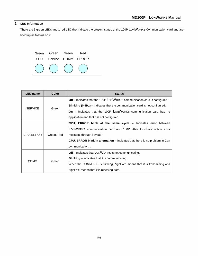
9. LED Information
There are 3 green LEDs and 1 red LED that indicate the present status of the 100P LONWORKS Communication card and are
lined up as follows on it.
LED name Color Status
SERVICE Green
Off – Indicates that the 100P LONWORKS communication card is configured.
Blinking (0.5Hz) – Indicates that the communication card is not configured.
On – Indicates that the 100P LONWORKS communication card has no
application and that it is not configured.
CPU, ERROR Green, Red
CPU, ERROR blink at the same cycle – Indicates error between
LONWORKS communication card and 100P. Able to check option error
message through keypad.
CPU, ERROR blink in alternation – Indicates that there is no problem in Can
communication. .
COMM Green
Off – Indicates that LONWORKS is not communicating.
Blinking – Indicates that it is communicating.
When the COMM LED is blinking, “light on” means that it is transmitting and
“light off” means that it is receiving data.
Green
Service
Green
COMM
Red
ERROR
Green
CPU
IOM_MarathonDrive_MD100P_LonWorksOptionManual_0415