Embed Size (px)
Citation preview

LOGO
HESSE AND RUSHTON METHOD
Pressure Vessels
1 9 8 5

LOGO
SHELL THICKNESS
where
tp = shell thickness (inch)
P = Max allowable working pressure (psi)
D = Inside diameter (inch)
S = Max allowable tensile stress (psi) (Table 6-6)
e = Efficiency of welded joint (Table 6-7)
C = Corrosion allowance
1 9 8 5
CPSe
PDt p
2

LOGO
SHELL THICKNESS
Applicable if:
1. tp < 0.10D
2. tp > tmin
1 9 8 5
CPSe
PDt p
2
1000
100min
D
t

LOGO
Allowable Stress Estimation
S = Su x Fm x Fs x Fr x Fa
1 9 8 5
WhereSu = Minimum Specified Tensile Strength
Fm = Material FactorFm = 1 for Grade A materialFm = 0.97 for Grade B material Fm = 0.92 for Grade C material
Fs = Temperature Factor (Use Table 6-7)
Fr = Stress Relief (SR) FactorFr = 1.06 When SR is applied
Fa = Radiographing FactorFa = 1.12 when Radiographing is applied and
subsequent repair of defects

LOGO
Minimum Specified Tensile Strength1 9 8 5
SpecifiedASME Minimum Allowable Unit Tensile Stress, Thousands psiCode Tensile at Various Temperatures, °FSpec. Material Data Strength - 20No. and Description Grade 1000 psi to
650700 750 800 850 900 950 1000
S-2 Steel plates - flange and A 45 9.0 8.8 8.4 6.9 5.7 4.4 2.6firebox quality B 50 10.0 9.6 9.0 7.5 6.0 4.4 2.6
S-1 Carbon steel for boilers 11.0 10.4 9.5 8.0 6.3 4.4 2.5Carbon-silicon steel, A 55 11.0 10.4 9.5 8.5 7.2 5.6 3.8 2.0
S-42 ordinary strength range B 60 12.0 11.4 10.4 9.1 7.4 5.6 3.8 2.0S-44 Molybdenum steel A 13.0 13.0 13.0 12.5 11.5 10.0 8.0 5.0S-43 Low-carbon nickel steel AS-55 Carbon-silicon steel, high 65
strength range, 4-1/2” A 13.0 12.3 11.1 9.4 7.6 5.6 3.8 2.0plates and under
S-44 B 14.0 14.0 14.0 13.5 12.0 10.2 8.0 5.0S-43 B 70 14.0 13.3 11.9 10.0 7.8 5.6 3.8 2.0S-55 B 14.0 13.3 11.9 10.0 7.8 5.6 3.8 2.0S-44 C 15.0 15.0 15.0 14.4 12.7 10.4 8.0 5.0S-43 C 75S-28 Chrome-manganese-
siliconA 15.0 14.1 12.4 10.1 7.8 5.6 3.8 2.0
alloy steel B 85

LOGO
Temperature Factor1 9 8 5
Metal Temperature, Plate and Forged°F Steel, % Cast Steel, %
Up to 650 25.0 16.7700 23.7 16.4750 21.0 14.7800 18.0 12.9850 15.0 11.1900 12.0 9.3950 9.0 7.5
1000 6.2 5.7

LOGO
Weld/Joint Efficiency1 9 8 5
EFFICIENCY CRITERIA
LAP WELD (For circumferential Joint) Single Lap Single Lap with plug weld Double Lap
BUTT WELD (For circumferential and longitudinal joints) Single Butt Single Butt with Back-up Strip Double Butt Double Butt with reinforce at center
55%65%65%
70%80%80%90%
tp < ⅝”tp < ⅝”tp > ⅝”
tp < ⅝”tp < 1¼”tp > 1¼”tp > 1¼”

LOGO
Stress Relief Factor1 9 8 5
Stress relieving is mandatory for:
1. tp > 1¼”
2. (For thinner plates)
where D has a minimum value of 20 inches
3. ASTM A – 150
4. ASTM A – 149 (under certain conditions)
120
50D
t p
LOGO
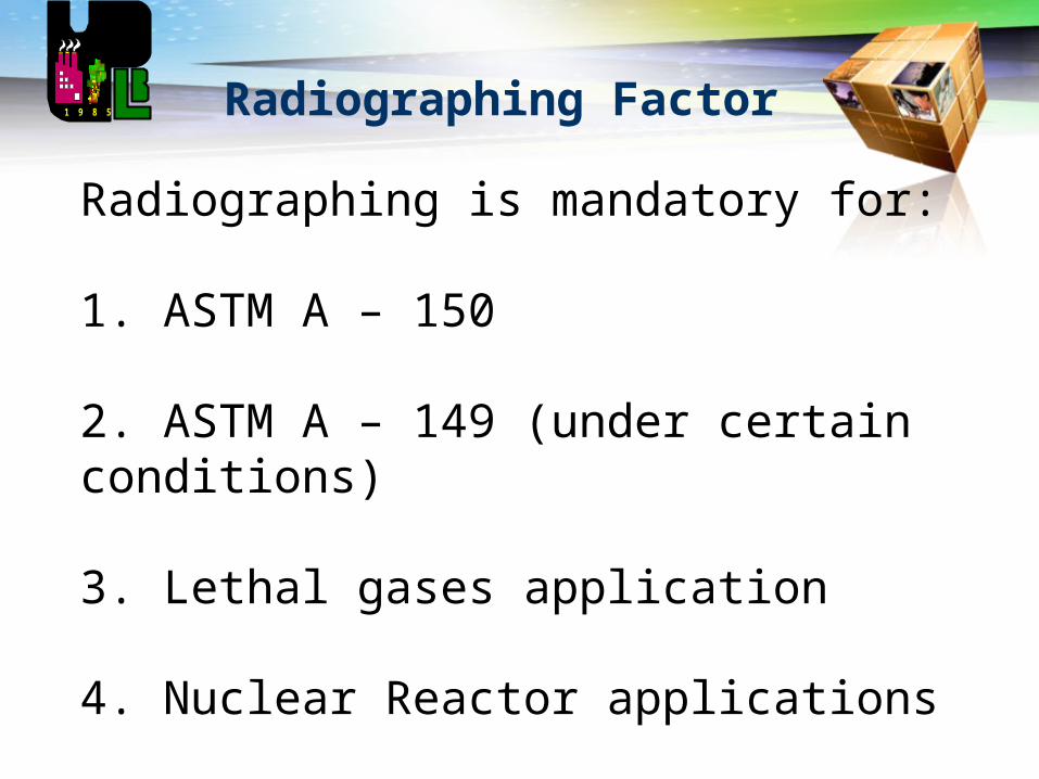
Radiographing Factor1 9 8 5
Radiographing is mandatory for:
1. ASTM A – 150
2. ASTM A – 149 (under certain conditions)
3. Lethal gases application
4. Nuclear Reactor applications

LOGO
Sample Problem 1
A 12 in diameter S-2 Grade A steel has a working pressure and temperature of 500 psi and 300F respectively. Determine the type of weld to be used and plate thickness using Hesse and Rushton method. Assume zero corrosion allowance.
1 9 8 5
LOGO
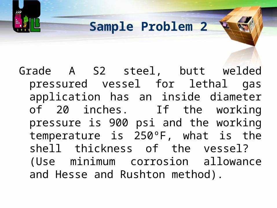
Sample Problem 2
Grade A S2 steel, butt welded pressured vessel for lethal gas application has an inside diameter of 20 inches. If the working pressure is 900 psi and the working temperature is 250ºF, what is the shell thickness of the vessel? (Use minimum corrosion allowance and Hesse and Rushton method).
1 9 8 5
LOGO
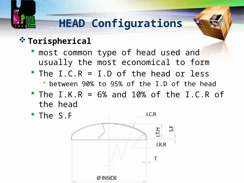
HEAD Configurations
Torispherical most common type of head used and usually the
most economical to form The I.C.R = I.D of the head or less
• between 90% to 95% of the I.D of the head
The I.K.R = 6% and 10% of the I.C.R of the head The S.F = 10mm and 30mm
1 9 8 5
LOGO
HEAD Configurations
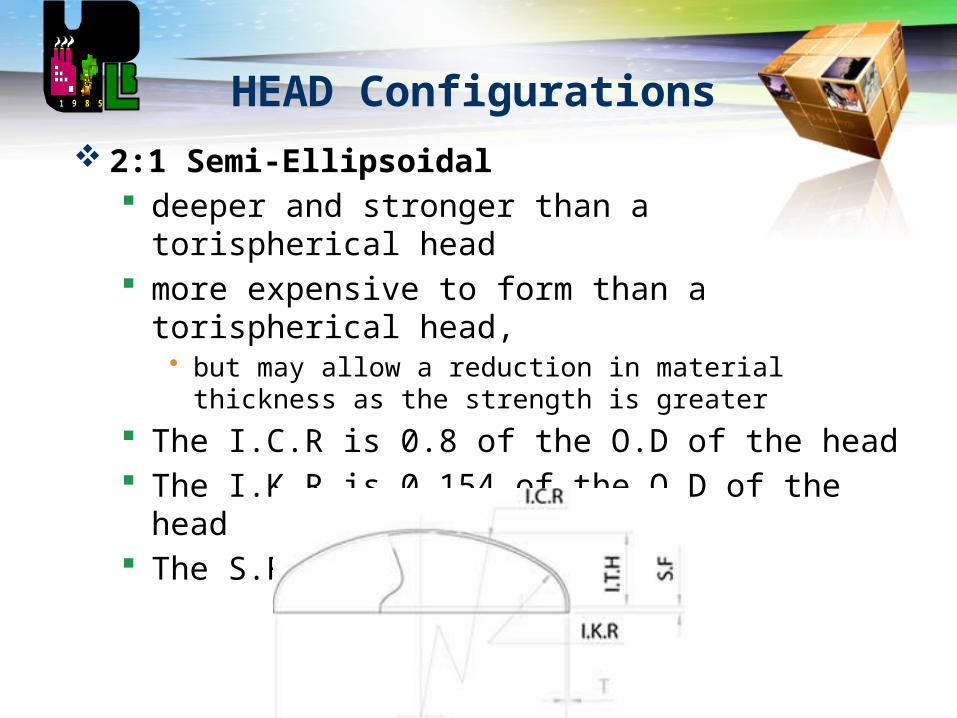
2:1 Semi-Ellipsoidal deeper and stronger than a torispherical head more expensive to form than a torispherical head,
• but may allow a reduction in material thickness as the strength is greater
The I.C.R is 0.8 of the O.D of the head The I.K.R is 0.154 of the O.D of the head The S.F =10mm and 30mm
1 9 8 5
LOGO
HEAD Configurations
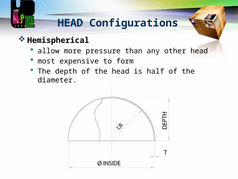
Hemispherical allow more pressure than any other head most expensive to form The depth of the head is half of the diameter.
1 9 8 5

LOGO
HEAD Configurations
Shallow Head commonly used atmospheric tanks not suitable for pressure vessels I.C.R =1.5 to 2.0 times the I.D of the head I.K.R = 32mm, 51mm or 76mm (depending on the
diameter and customer requirements)
The S.F =10mm and 30mm
1 9 8 5
LOGO
HEAD Configurations
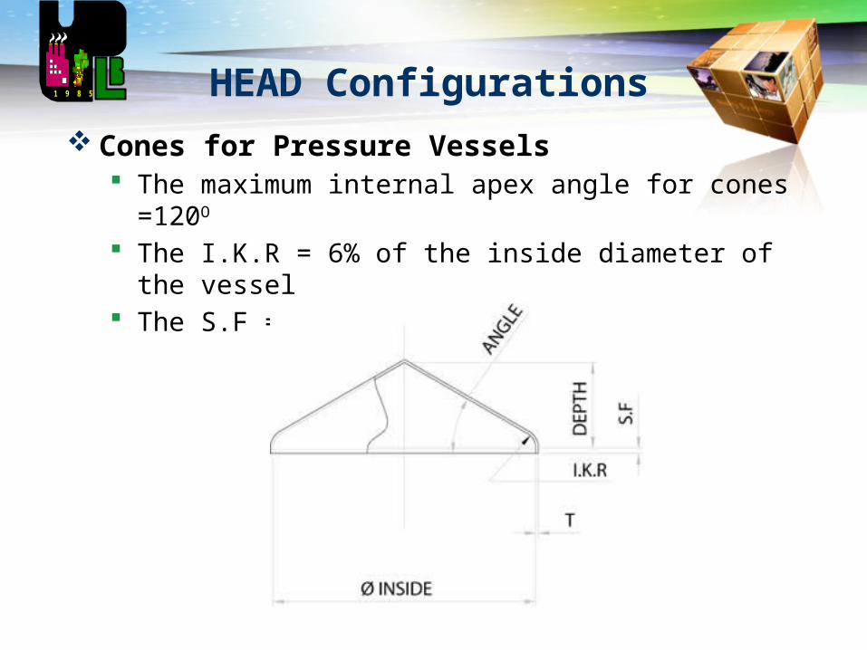
Cones for Pressure Vessels The maximum internal apex angle for cones =120O
The I.K.R = 6% of the inside diameter of the vessel The S.F =10mm and 30mm
1 9 8 5

LOGO
HEAD Configurations
Flat. A flat end with a knuckled outer edge used as bases on vertical atmospheric tanks and lids for
smaller tanks The I.K.R =25mm, 32mm and 51mm The S.F. = 10mm and 30mm
1 9 8 5

LOGO
HEAD Configurations
Dish. used for atmospheric tanks and vessels and for bulk
heads or baffles inside horizontal tanks or tankers Typically the I.C.R is equal to the diameter
1 9 8 5
LOGO
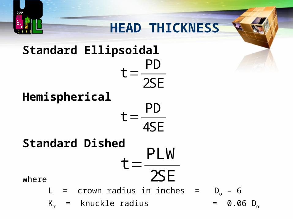
HEAD THICKNESS
Standard Ellipsoidal
Hemispherical
Standard Dished
where
L = crown radius in inches = Do – 6
Kr = knuckle radius = 0.06 Do
1 9 8 5
SE2
PDt
SE4
PDt
SE2
PLWt
LOGO
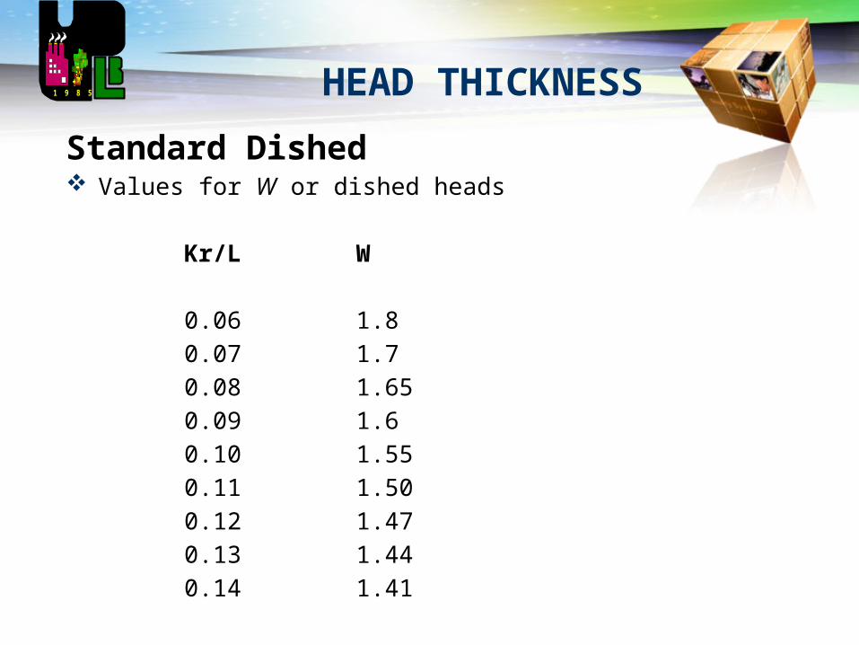
HEAD THICKNESS1 9 8 5
Standard Dished Values for W or dished heads
Kr/L W
0.06 1.8
0.07 1.7
0.08 1.65
0.09 1.6
0.10 1.55
0.11 1.50
0.12 1.47
0.13 1.44
0.14 1.41

LOGO
HEAD THICKNESS1 9 8 5
Standard Dished Values for W or dished heads
Kr/L W
0.15 1.40
0.16 1.38
0.17 1.37
0.18 1.35
0.19 1.32
0.20 1.30
0.25 1.25
0.50 1.12
1.0 1.0

LOGO
HEAD THICKNESS
Flat Heads
*Lap Welded w/ or w/o Plug Welds:
*Single or Double V Butt Welded
*Cut from Solid PlateStandard Dished
1 9 8 5
S
P3.0dt
S
P25.0dt
S
P5.0dt