Embed Size (px)
Citation preview

1
Logic Synthesis
Prof. Dejan Marković [email protected]
EEM216A Fall 2012
D. Markovic / Slide 2
VLSI Design Flow
RTL Design (Verilog HDL)
Specifications & System Simulation (MATLAB, Simulink, C++)
Logic Synthesis ( DC)
PnR ( SoC Encounter)
DRC & LVS ( Calibre)
Today
11.2

2
D. Markovic / Slide 3
Logic Synthesis
• Conceptual overview & tool setup
• RTL modification
• Technology libraries
• Design environment & constraints
• Major synthesis commands
• Gate-level simulation
11.3
D. Markovic / Slide 4
Synthesis:
WHY, HOW, WHAT
11.4

3
D. Markovic / Slide 5
Why Synthesis?
• Quick (re)design time
• Separate functionality, technology-dependent parameters, and design constraints
• Fast timing/area/power estimates
11.5
D. Markovic / Slide 6
How to do Synthesis?
Optimized Gate-level Netlist
Architectural Mapping Designware Lib
Logic Optimization Technology Lib
RTL Design (your .v files)
Database of Adders, Multipliers, Shifters…
Gate sizing, Logic Transformation
RCA, CLA…
MUX
AND + OR + INV…
Synthesis Commands (your .tcl files)
11.6
4
D. Markovic / Slide 7
What can Synthesis Provide?
• Timing/Area/Power reports • Gate-level netlist (.vg) & timing info. in standard
delay format (.sdf) for timing-aware simulation
A 1000 0010
B 0011 1100
C 1011 1110
A 1000 0010
B 0011 1100
C 1011 1110
assign C = A + B ;
before synth. after synth.Glitch & Delay 11.7
D. Markovic / Slide 8
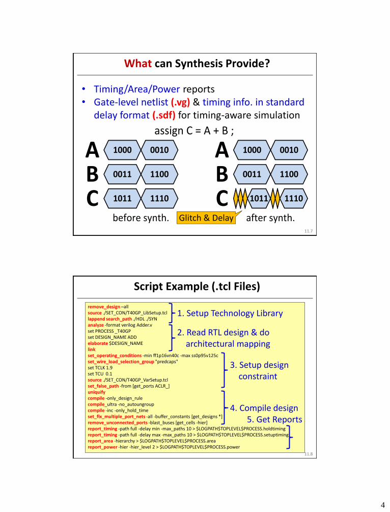
Script Example (.tcl Files)
remove_design –all source ./SET_CON/T40GP_LibSetup.tcl lappend search_path ./HDL ./SYN analyze -format verilog Adder.v set PROCESS _T40GP set DESIGN_NAME ADD elaborate $DESIGN_NAME link set_operating_conditions -min ff1p16vn40c -max ss0p95v125c set_wire_load_selection_group "predcaps" set TCLK 1.9 set TCU 0.1 source ./SET_CON/T40GP_VarSetup.tcl set_false_path -from [get_ports ACLR_] uniquify compile -only_design_rule compile_ultra -no_autoungroup compile -inc -only_hold_time set_fix_multiple_port_nets -all -buffer_constants [get_designs *] remove_unconnected_ports -blast_buses [get_cells -hier] report_timing -path full -delay min -max_paths 10 > $LOGPATH$TOPLEVEL$PROCESS.holdtiming report_timing -path full -delay max -max_paths 10 > $LOGPATH$TOPLEVEL$PROCESS.setuptiming report_area -hierarchy > $LOGPATH$TOPLEVEL$PROCESS.area report_power -hier -hier_level 2 > $LOGPATH$TOPLEVEL$PROCESS.power
1. Setup Technology Library
2. Read RTL design & do architectural mapping
3. Setup design constraint
4. Compile design 5. Get Reports
11.8
5
D. Markovic / Slide 9
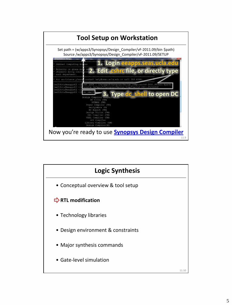
Tool Setup on Workstation
Now you’re ready to use Synopsys Design Compiler
1. Login eeapps.seas.ucla.edu 2. Edit .cshrc file, or directly type
3. Type dc_shell to open DC
Set path = (w/apps3/Synopsys/Design_Compiler/vF-2011.09/bin $path) Source /w/apps3/Synopsys/Design_Compiler/vF-2011.09/SETUP
11.9
D. Markovic / Slide 10
Logic Synthesis
• Conceptual overview & tool setup
• RTL modification
• Technology libraries
• Design environment & constraints
• Major synthesis commands
• Gate-level simulation
11.10

6
D. Markovic / Slide 11
The Importance of HDL Coding Styles
Different coding styles that are functionally eqvl. may be mapped into HWs having different timing/area
Good coding style: Better starting point for DC to reach optimal gate-level results
E = A + B + C + D E = (A + B) + (C + D)
A
B C D
E A
B
EC
D
11.11
D. Markovic / Slide 12
Enable Cool Features from DC
#1: Gated Clock
#2: Synopsys Directives
11.12

7
D. Markovic / Slide 13
Go Low-Power using Clock Gating
30~50% Power Savings @ Block Level
Two steps for gated-clock syn.: (1)Delete Else state-ments in seq. logic; (2)DC commands (shown later)
QD
ENCLK
1
0
DFF
always@(posedge CLK) if(EN) Q <= D ; else Q <= Q ;
always@(posedge CLK) if(EN) Q <= D ;
STILL NO
EN
CLK
Latch
D Q
DFF
11.13
D. Markovic / Slide 14
Case Directives Supported by DC (1)
tell DC to interpret incomplete case specially Keyword: // synopsys_parallel_case
// synopsys_full_case (RTL simulator ignores, but DC understands)
reg A, B; wire [2:0] SEL ; always@(*) {A, B} = 2’b0 ; casez(SEL) 3’b?11: B = 1 ; 3’b1??: A = 1 ; endcase
Put it after the case declaration
// synopsys_parallel_case
11.14

8
D. Markovic / Slide 15
Case Directives Supported by DC (2)
• Synopsys_full_case • Treats o/p of unstated case items as don’t care • Ignored if the case statement is complete • As a result, no latch is created
• Synopsys_parallel_case
• Treats all case items as non-overlapped; implement each of them seperately
• As a result, no priority logic is created
Note: Potential discrepancy b/w RTL simulation and gate-level simulation
11.15
D. Markovic / Slide 16
Example: RTL the Same, Gate-Level Different
reg A, B; wire [2:0] SEL ; always@(*) {A, B} = 2’b0 ; casez(SEL) 3’b?11: B = 1 ; 3’b1??: A = 1 ; endcase
reg A, B; wire [2:0] SEL ; always@(*) // synopsys_parallel_case {A, B} = 2’b0 ; casez(SEL) 3’b?11: B = 1 ; 3’b1??: A = 1 ; endcase
Lec. 8.46
SEL[2]
SEL[1]SEL[0]
B
A
SEL[2]
SEL[1]SEL[0]
B
A
Priority Logic
Independent Logic
11.16

9
D. Markovic / Slide 17
Logic Synthesis
• Conceptual overview & tool setup
• RTL modification
• Technology libraries
• Design environment & constraints
• Major synthesis commands
• Gate-level simulation
11.17
D. Markovic / Slide 18
What are Technology Libraries About? (1)
library ("saed32rvt_ss0p95v125c") { operating_conditions (ss0p95v125c) { process : 0.99; voltage : 0.950000; temperature : 125.000000; tree_type : "best_case_tree"; } wire_load (ForQA) { capacitance : 0.029396; resistance : 2.273000e-03; area : 0.010000; slope : 30.285426; fanout_length("1", "8.2750360"); ... } wire_load ("8000") { ... } ... wire_load_selection (predcaps) { wire_load_from_area(0.000000,200.000000, "ForQA"); wire_load_from_area(200.000000,8000.000000, "8000"); ... }
Operating condition (process, voltage, temp.)
Wire-load model (rough est. of wiring
parasitics before PnR)
Wire-load selection (based on synth.
area of your design)
11.18
10
D. Markovic / Slide 19
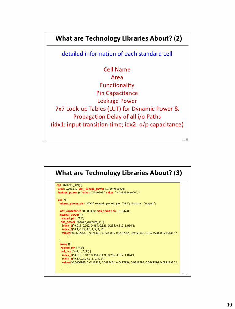
What are Technology Libraries About? (2)
detailed information of each standard cell
Cell Name Area
Functionality Pin Capacitance Leakage Power
7x7 Look-up Tables (LUT) for Dynamic Power & Propagation Delay of all i/o Paths
(idx1: input transition time; idx2: o/p capacitance) 11.19
D. Markovic / Slide 20
What are Technology Libraries About? (3)
cell (AND2X1_RVT) { area : 2.033152; cell_leakage_power : 1.404953e+05; leakage_power () { when : "!A1&!A2"; value : "5.6919234e+04"; } ... pin (Y) { related_power_pin : "VDD"; related_ground_pin : "VSS"; direction : "output"; ... max_capacitance : 8.000000; max_transition : 0.194746; internal_power () { related_pin : "A1"; rise_power ("power_outputs_1") { index_1("0.016, 0.032, 0.064, 0.128, 0.256, 0.512, 1.024"); index_2("0.1, 0.25, 0.5, 1, 2, 4, 8"); values("0.9612064, 0.9624440, 0.9509065, 0.9587265, 0.9569466, 0.9523558, 0.9245481", \ ... } timing () { related_pin : "A1"; cell_rise ("del_1_7_7") { index_1("0.016, 0.032, 0.064, 0.128, 0.256, 0.512, 1.024"); index_2("0.1, 0.25, 0.5, 1, 2, 4, 8"); values("0.0400985, 0.0415339, 0.0437422, 0.0477826, 0.0546696, 0.0667816, 0.0888995", \ ... }
11.20

11
D. Markovic / Slide 21
Access Synopsys 32nm Technology Libs.
Path: /w/apps2/public.2/tech/synopsys/32-
28nm/SAED32_EDK/lib/stdcell_rvt/db_nldm (rvt: regular-Vth. Can change to hvt and lvt for high-Vth and low-Vth libraries)
There you can find various libraries, each with different design corners. We select
saed32rvt_ff1p16vn40c.db for hold-time analysis &
saed32rvt_ss0p95v125c.db for setup-time analysis
Note: .db files are only used by DC. If you want to read library information as in page 11.18~20, access the corresponding .lib files
11.21
D. Markovic / Slide 22
Setup Technology Libraries
set search_path “$search_path \ /w/apps2/public.2/tech/synopsys/32-28nm/SAED32_EDK/lib/stdcell_rvt/db_nldm” set target_library “saed32rvt_ff1p16vn40c.db saed32rvt_ss0p95v125c.db” set link_library “* saed32rvt_ff1p16vn40c.db saed32rvt_ss0p95v125c.db dw_foundation.sldb” set synthetic_library “dw_foundation.sldb” # Define work path (note: The work path must exist, so you need to create a folder WORK first) define_design_lib WORK -path ./WORK set alib_library_analysis_path “./alib-52/”
(save above scripts in a .tcl file, and source it after you open DC)
• DC follows search_path to find libraries you specify • DC uses cells in target library for logic optimization (so
we need to do set_target_library first) • Remember: Use backslash \ before changing lines to
avoid compilation errors.
11.22

12
D. Markovic / Slide 23
Logic Synthesis
• Conceptual overview & tool setup
• RTL modification
• Technology libraries
• Design environment & constraints
• Major synthesis commands
• Gate-level simulation
11.23
D. Markovic / Slide 24
Large
Area
Small
Short Delay Long
•
•
• • • •
Synthesis is Constraint-Driven
Courtesy: Synopsys
You set the goals (through design constraints) DC optimizes the design to meet your goals
11.24

13
D. Markovic / Slide 25
Logic Synthesis is Timing-Driven
logic logic logic logic logic
Clk “set_input_delay” (affects input logic)
“set_output_delay” (affects output logic)
“create_clock” (affects internal logic)
(input) (internal) (output)
your current design
• Input delay: Arrival of an external path w.r.t. the clock edge
• Output delay: timing from an o/p (of current design) to a register i/p (of other submodules)
11.25
D. Markovic / Slide 26
Describe Design Constraints
• Clocks • Period, latency, uncertainty
• Design rules • Maximum transition • Maximum capacitance • Maximum fanout
• Input-related • Driving cells, Input delay
• Output-related • Load, Output delay
• Exception paths • False paths, multi-cycle paths
• Optimization goal • Maximum area/power
# Especially important for bottom-up design methodology # Accurate constraints (not too tight/loose): Good integ. results
11.26

14
D. Markovic / Slide 27
Ideal vs. Real Clock
latency uncertainty transition
(jitter+ skew)
ideal clock
Courtesy: Synopsys
11.27
period
D. Markovic / Slide 28
Clock Description
• create_clock: define clock’s waveform (e.g. period)
• set_fix_hold: respect the hold time requirement of all
clocked flip-flops
• set_dont_touch_network: do not buffer clock network
• Specify uncertainty (skew + jitter) of clock network
11.28
create_clock -name “CLK" -period 2.0 [get_ports “CLK"]
set_fix_hold CLK
set_dont_touch_network [get_clocks “CLK"]
set_clock_uncertainty 0.1 [get_clocks “CLK"]
15
D. Markovic / Slide 29
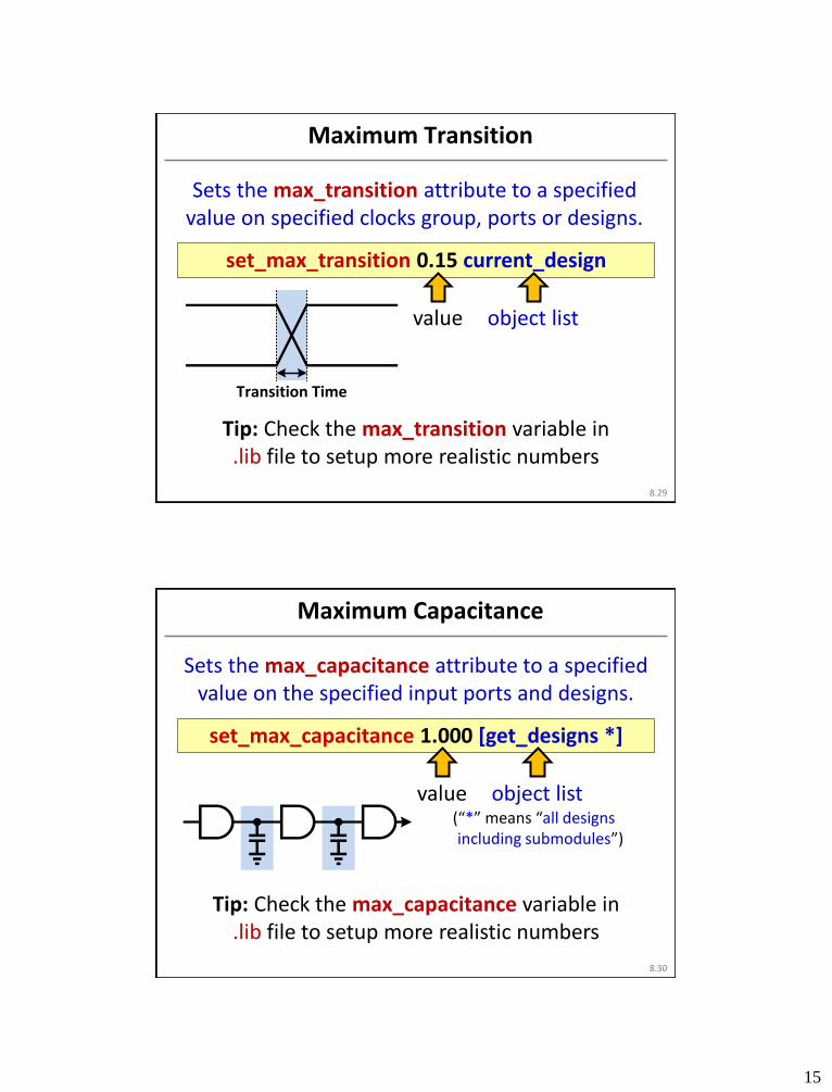
Maximum Transition
Sets the max_transition attribute to a specified value on specified clocks group, ports or designs.
8.29
set_max_transition 0.15 current_design
value
object list
Tip: Check the max_transition variable in .lib file to setup more realistic numbers
Transition Time
D. Markovic / Slide 30
Maximum Capacitance
Sets the max_capacitance attribute to a specified value on the specified input ports and designs.
(“*” means “all designs including submodules”)
8.30
set_max_capacitance 1.000 [get_designs *]
value
object list
Tip: Check the max_capacitance variable in .lib file to setup more realistic numbers

16
D. Markovic / Slide 31
Maximum Fanout
Sets the max_fanout attribute to a specified value on specified input ports and/or designs.
8.31
set_max_fanout 1.000 [get_designs *]
value
object list
Tip: Check the fanout_load variable of cells in .lib file to setup more realistic numbers
Gate Fanout Load
Total Fanout Load = 0.9
0.1
0.8
D. Markovic / Slide 32
Output Load
Sets the set_load attribute to a specified value on specified output ports and/or designs.
8.32
set_load 1.000 [all_outputs]
value
object list
Tip: Check the capacitance variable of cell input pins in .lib file to setup more realistic numbers
Design

17
D. Markovic / Slide 33
Driving Cells
Sets attributes on input or inout ports of the current design, specifying that a library cell or
output pin of a library cell drives specified ports.
set_driving_cell [-library lib] [-lib_cell lib_cell_name] [-pin pin_name]
8.33
set ALL_IN_BUT_CLK [ remove_from_collection [all_inputs] “CLK"]
set_driving_cell -no_design_rule -library saed32rvt_ss0p95v125c.db:saed32rvt_ss0p95v125c -
lib_cell DFFASRX2_RVT -pin Q $ALL_IN_BUT_CLK
D. Markovic / Slide 34
Input & Output Delay
Sets delay on pins or ports relative to a (ideal) clock signal.
set_input_delay -max delay_value [-clock clock_name] set_input_delay -min delay_value [-clock clock_name]
set_output_delay -max delay_value [-clock clock_name] set_output_delay -min delay_value [-clock clock_name]
8.34
set_input_delay 0.6 -clock “CLK" $ALL_IN_BUT_CLK set_input_delay -min 0.3 -clock “CLK" $ALL_IN_BUT_CLK
set_output_delay 0.6 -clock “CLK" [all_outputs] set_output_delay -min 0.3 -clock “CLK" [all_outputs]

18
D. Markovic / Slide 35
False Paths
Removes timing constraints from particular paths, but still needs to satisfy design rule
(transition, capacitance, fanout).
set_false_path -from [from_list]
8.35
set_false_path -from [get_ports ACLR_] set_false_path -from [get_ports SI]
D. Markovic / Slide 36
Maximum Area/Power
11.36
set_max_total_power 0.0
set_max_area 0.0
desired area
desired power
Optimization goals for your design (DC will do it best to satisfy them, w/o violating the three design rules)

19
D. Markovic / Slide 37
Operating Condition
Defines the operating conditions for the current design.
set_operating_conditions
[-min min_condition] [-max max_condition]
8.37
set_operating_conditions -min ff1p16vn40c -max ss0p95v125c
for hold-time check
for setup-time check
D. Markovic / Slide 38
Wire-load Models and Modes
Specify a selection group to use for determining a wire load model to be assigned to designs and
cells or to a specified cluster.
set_wire_load_selection_group group_name -max set_wire_load_selection_group group_name -min
8.38
set_wire_load_selection_group "predcaps"
DC will select proper model based on synthesis area (again, lookup this name in .lib file)

20
D. Markovic / Slide 39
Logic Synthesis
• Conceptual overview & tool setup
• RTL modification
• Technology libraries
• Design environment & constraints
• Major synthesis commands
• Gate-level simulation
11.39
D. Markovic / Slide 40
Preview: Use Synthesis Commands Properly
• Not all commands introduced are necessarily needed
• Things MUST do
Analyze, elaborate, and link design
Compile design • Things can do based on your needs
Ungroup; Uniquify
Clock gating creation
Remove unconnected ports
Suggestion: Learn by playing w/ different commands and observing the differences
11.40
21
D. Markovic / Slide 41
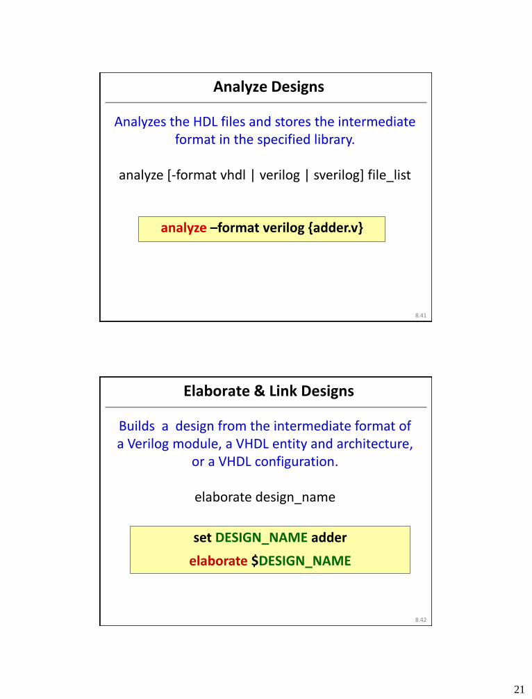
Analyze Designs
Analyzes the HDL files and stores the intermediate format in the specified library.
analyze [-format vhdl | verilog | sverilog] file_list
8.41
analyze –format verilog {adder.v}
D. Markovic / Slide 42
Elaborate & Link Designs
Builds a design from the intermediate format of a Verilog module, a VHDL entity and architecture,
or a VHDL configuration.
elaborate design_name
8.42
set DESIGN_NAME adder
elaborate $DESIGN_NAME

22
D. Markovic / Slide 43
Ungroup & Uniquify
Removes a level of hierarchy.
ungroup cell_list | -all [-flatten]
Removes multiple-instantiated hierarchy in the current design by creating a unique design for
each of the cell instances.
uniquify [-force] [-cell cell_list]
8.43
ungroup -flatten -all
uniquify
D. Markovic / Slide 44
Compile
Performs logic-level and gate-level synthesis and optimization on the current design.
compile [-no_design_rule | -only_design_rule | -only_hold_time] [-map_effort medium | high] [-
boundary_optimization]
8.44
compile –only_design_rule compile –map_medium high
compile –boundary_optimization compile –only_hold_time

23
D. Markovic / Slide 45
Gated Clock Creation
11.45
set_clock_gating_registers -include_instances [all_registers -clock "CLK"] set_clock_gating_style -num_stages 2 -sequential_cell latch -minimum_bitwidth 8 -max_fanout 32 insert_clock_gating –global propagate_constraints -gate_clock
Four commands to construct clock gating (note: Modify RTL as in pp. 13 to enable this feature)
D. Markovic / Slide 46
Remove Unconnected Ports
Removes unconnected ports or pins from cells, references, and subdesigns.
11.46
remove_unconnected_ports -blast_buses [get_cells -hier]
24
D. Markovic / Slide 47
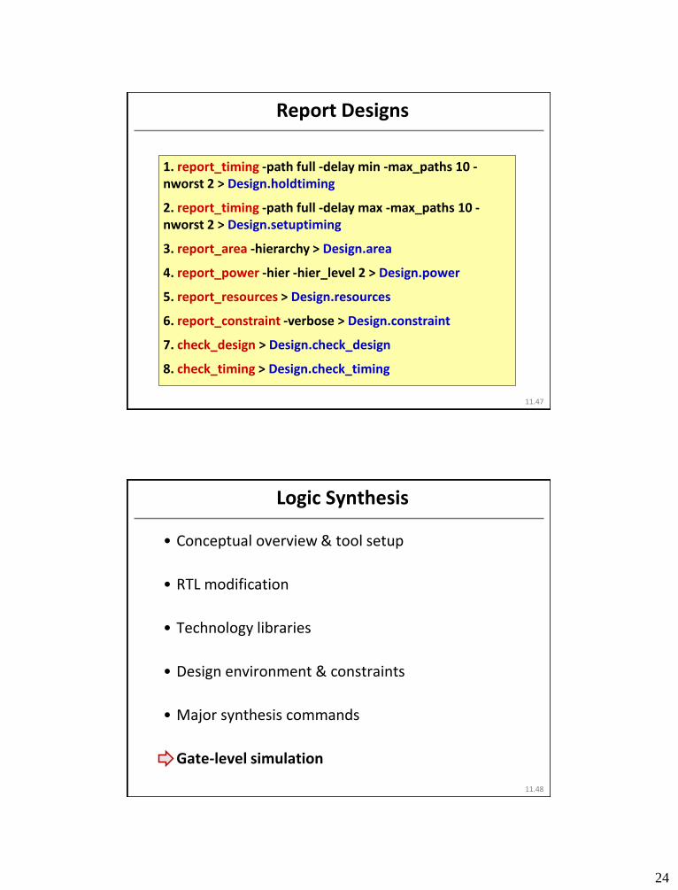
Report Designs
11.47
1. report_timing -path full -delay min -max_paths 10 -nworst 2 > Design.holdtiming
2. report_timing -path full -delay max -max_paths 10 -nworst 2 > Design.setuptiming
3. report_area -hierarchy > Design.area
4. report_power -hier -hier_level 2 > Design.power
5. report_resources > Design.resources
6. report_constraint -verbose > Design.constraint
7. check_design > Design.check_design
8. check_timing > Design.check_timing
D. Markovic / Slide 48
Logic Synthesis
• Conceptual overview & tool setup
• RTL modification
• Technology libraries
• Design environment & constraints
• Major synthesis commands
• Gate-level simulation
11.48

25
D. Markovic / Slide 49
Slight Modification of Original Testbench.v
• RTL simulation: design.v + testbench.v • Gate-level simulation: design.vg + design.sdf
(from DC) + testbench.v (w/ slight modification)
11.49
`timescale 1ns/10ps module Test ; ADD AddSim(…) ; … … … … … … endmodule
`timescale 1ns/10ps module Test ; ADD AddSim(…) ; initial begin end … … endmodule
$sdf_annotate(“design.sdf", AddSim);
D. Markovic / Slide 50
Any Questions?
The “Man” is always there for you, 24/7 (type man <syntax you want to lookup> in DC)
or check out various user manuals online
11.50

26
D. Markovic / Slide 51
Synthesis Summary
11.51
• Synthesis tool makes VLSI design a lot easier • Easy to use: .v files + .tcl files • Easy to switch designs to any technology by
changing associated libraries • Easy to have accurate area/timing/power estimate • Easy to match the best archit. with design constraints
• But… not a substitue for thinking
• Mind your coding styles • Handmade optimization (e.g. using shift-and-add for
constant multiplication) still needed