Embed Size (px)
DESCRIPTION
Introduction to Logic Gates
Citation preview

LOGIC GATES
By:Alvin T. Dela Peña, ECE

CHAPTER GOALS
• Identify the basic gates and describe the behavior of each
• Combine basic gates into circuits• Describe the behavior of a gate or circuit using
Boolean expression, truth tables and logic diagrams.

• Logic gates are the actual physical implementations of the logical operators.
• These gates form the basic building blocks for all digital logic circuits.
• Logic gates process signals which represent true or false.

Basic Gates
• A NOT gate accepts one input value and produces one output value


• An AND gate accepts two input signals• If the two input values for an AND gate are
both 1, the output is 1; otherwise, the output is 0


• If the two input values are both 0, the output value is 0; otherwise, the output is 1


• XOR, or exclusive OR, gate– An XOR gate produces 0 if its two inputs are the
same, and a 1 otherwise– Note the difference between the XOR gate
and the OR gate; they differ only in one input situation
– When both input signals are 1, the OR gate produces a 1 and the XOR produces a 0


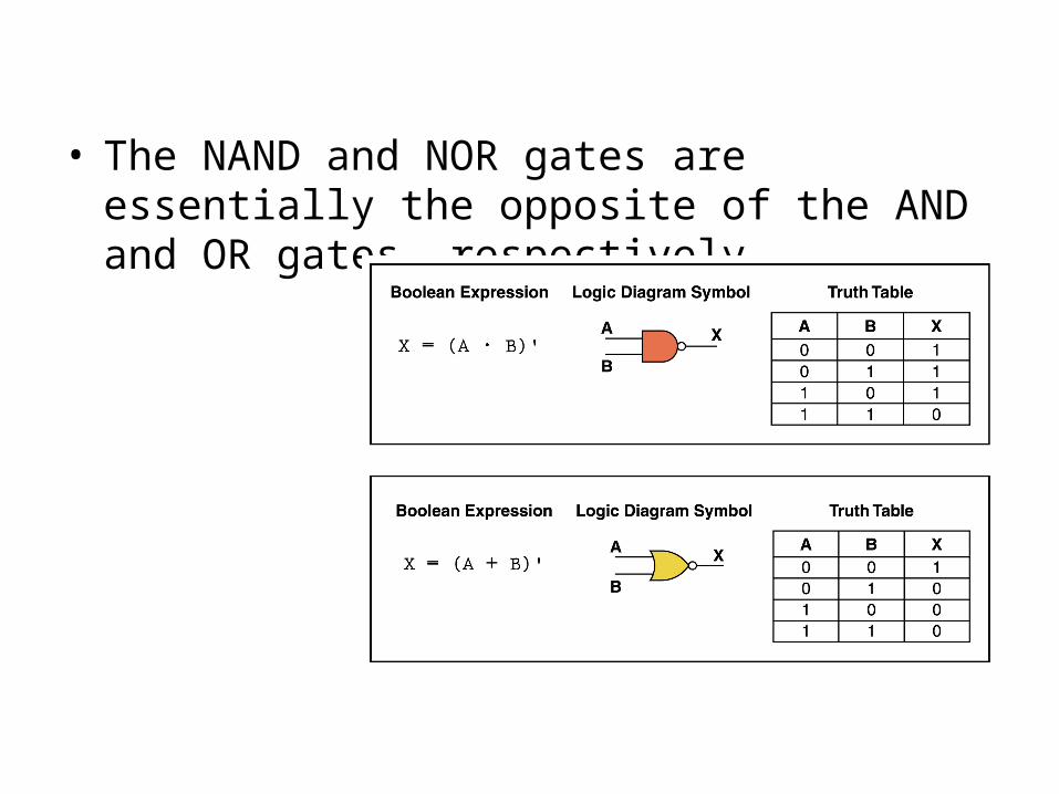
• The NAND and NOR gates are essentially the opposite of the AND and OR gates, respectively


Combinational Circuits• Gates are combined into circuits by using the output
of one gate as the input for another.

Implementing a function from a Boolean Expression
• Consider the following Boolean expression: A(B + C)
DCBAY
CBAX

Generating a Boolean expression from a logic diagram

Implementing a logic function from a Truth table

Boolean Identities

In some cases it is possible to simplify logic expressions using the rules of Boolean algebra
-this expression can be simplified into:
CAACBCAABCX
ABCX


![Gates and Logic: From Transistors to Logic Gates and Logic ......Gates and Logic: From Transistors to Logic Gates and Logic Circuits [Weatherspoon, Bala, Bracy, and Sirer] Prof. Hakim](https://img.dokumen.tips/doc/110x75/5fa95cb6eb1af8231472f381/gates-and-logic-from-transistors-to-logic-gates-and-logic-gates-and-logic.jpg)