Embed Size (px)
Citation preview

EQUIPMENT OPERATION MANUAL
Loctite 200, 300, and 400 Series
Benchtop Robots
Book 1 of 4: Quick Start
A
Company

FOR SAFE USE
Safety Notes Read the following Warnings and Cautions thoroughly for the safe use of the Desktop Robot. Keep them in mind during use in order to prevent injuries and damage to property.
Be sure to heed the following Warnings and Cautions faithfully. Various symbols are used to indicate the matters to be attended to. Please read the following explanations to understand what each symbol means.
λ Symbols for the Degree of Damage and Danger The following symbols indicate the degree of damage and danger which may result if you neglect the safety notes.
The Warnings are mainly concerned with incorrect and dangerous uses which could lead to serious damage, such as death or serious injuries.
Warnings
The Cautions are mainly concerned with improper operation which could lead to minor damage, such as injuries or damage to properties.
λ Symbols for the Content of the Danger and Preventive Measures
The following symbols indicate the types of the safety measures you should take.
indicates the content of the safety measures you should take.
Indicates prohibition.
Cautions
Quick
Do not touch.
Never do this.
Do not disassemble, modify or repair.
S
General Caution
Be sure to unplug the power cord from the wall outlet.
Indicates obligation.
Be sure to check grounding.
Be sure to follow these directions.
tart Dispensing i

FOR SAFE USE continued from the previous page
Quick Start
Be sure to check groundingImproper grounding can cause Be sure to use power in the Otherwise electric shocks or fir Plug the power cord into theOtherwise the input can becomMake sure that the power plug
Be sure to unplug the powergrease the machine. Otherwise electric shocks or fir Stop operation and unplug iabnormalities, such as pungwhich you purchased the prIf you continue operation, electInstall the product in a placeconditions. If the machine falls down or turmay ensue. Be sure to prepare protectivto avoid injury when you insEntering the robot’s work range Do not attempt to disassembDisassembly or modification co Use the machine indoors whpresent. Emission and accumulation of
Warnings
Dispensing ii
. electric shocks or fire.
range indicated on the unit . e may ensue.
wall outlet firmly. e hot and may lead to fire.
is clean.
cord from the wall outlet when you examine or
e may ensue.
mmediately whenever you sense any ent odor. Immediately contact the dealer from oduct. ric shock, fire or malfunction may ensue. which can endure the weight and running
ns over due to improper installation, injuries or defects
e measures such as an area sensor or enclosure tall the product. during operation could lead to injury.
le or modify the machine. uld lead to electric shocks, fire or malfunction.
ere no flammable gas nor corrosive gas is
corrosive gas could lead to fire.

FOR SAFE USE continued from the previous page
Be sure to unplug the power cord from the wall outlet if the robot will be left unused for a long time. Otherwise gathered dust could lead to fire. Be sure to use power in the proper range. Otherwise fire or malfunction may ensue. When you use an extension cord, keep it off from water or oil. Otherwise electric shocks or fire may ensue.
Quick Start
Be sure to check grounding. Improper grounding could lead to malfunction or defects. Use the Desktop Robot in an environment of 0 to 40 degrees centigrade and humidity of 20 to 95 percent without condensation. Otherwise malfunction may ensue. Use the machine where no electric noise is present. Otherwise malfunction or defects may ensue. Use the machine where it is not exposed to direct sunlight. Otherwise malfunction or defects may ensue. Be sure to confirm that the tools such as an electric screwdriver unit, etc. are connected properly. Otherwise injuries or defects may ensue. Check the mounting screws regularly so that they are always firmly tightened. Loosened screws may lead to injuries or defects.
Warnings
Cautions
Dispensing iii

FOR SAFE USE continued from the previous page
Be sure to confirm the wiring tImproper wiring may lead to malf Be sure to secure the movableOtherwise injuries or defects may Do not bump or jar the machinOtherwise defects may ensue. Keep hand away from moving
Quick Start
Cautions
o the main unit. unctions or defects.parts of the robot before transportation. ensue.
e while it is being transported or installed.
parts to avoid injury.
Dispensing iv
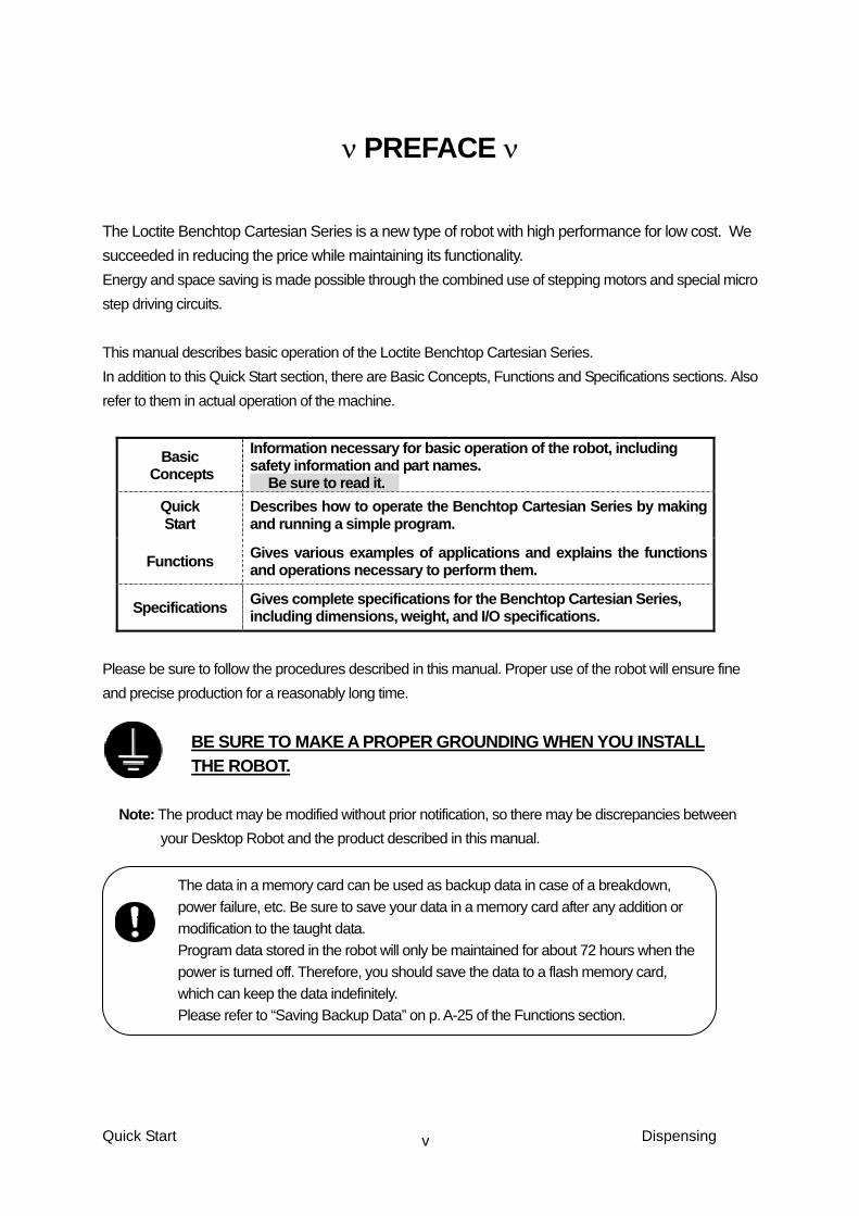
ν PREFACE ν The Loctite Benchtop Cartesian Series is a new type of robot with high performance for low cost. We succeeded in reducing the price while maintaining its functionality. Energy and space saving is made possible through the combined use of stepping motors and special micro step driving circuits. This manual describes basic operation of the Loctite Benchtop Cartesian Series. In addition to this Quick Start section, there are Basic Concepts, Functions and Specifications sections. Also refer to them in actual operation of the machine.
Basic Concepts
Information necessary for basic operation of the robot, including safety information and part names. � Be sure to read it. �
Quick Start
Describes how to operate the Benchtop Cartesian Series by making and running a simple program.
Functions Gives various examples of applications and explains the functions and operations necessary to perform them.
Specifications Gives complete specifications for the Benchtop Cartesian Series, including dimensions, weight, and I/O specifications.
Please be sure to follow the procedures described in this manual. Proper use of the robot will ensure fine and precise production for a reasonably long time.
BE SURE TO MAKE A PROPER GROUNDING WHEN YOU INSTALL THE ROBOT.
Note: The product may be modified without prior notification, so there may be discrepancies between
your Desktop Robot and the product described in this manual.
The data in a memory card can be used as backup data in case of a breakdown, power failure, etc. Be sure to save your data in a memory card after any addition or modification to the taught data. Program data stored in the robot will only be maintained for about 72 hours when the power is turned off. Therefore, you should save the data to a flash memory card, which can keep the data indefinitely. Please refer to “Saving Backup Data” on p. A-25 of the Functions section.
Quick Start Dispensing v
ν CONTENTS ν
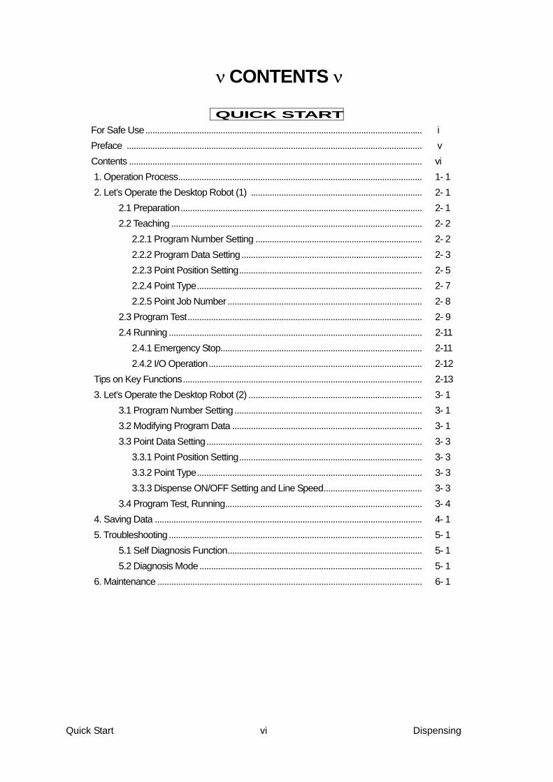
QUICK START For Safe Use...................................................................................................................... i Preface .............................................................................................................................. v Contents ............................................................................................................................. vi 1. Operation Process........................................................................................................ 1- 1 2. Let’s Operate the Desktop Robot (1) ......................................................................... 2- 1 2.1 Preparation....................................................................................................... 2- 1 2.2 Teaching ........................................................................................................... 2- 2 2.2.1 Program Number Setting ....................................................................... 2- 2 2.2.2 Program Data Setting............................................................................. 2- 3 2.2.3 Point Position Setting.............................................................................. 2- 5 2.2.4 Point Type................................................................................................ 2- 7 2.2.5 Point Job Number ................................................................................... 2- 8 2.3 Program Test.................................................................................................... 2- 9 2.4 Running ............................................................................................................ 2-11 2.4.1 Emergency Stop...................................................................................... 2-11 2.4.2 I/O Operation........................................................................................... 2-12 Tips on Key Functions...................................................................................................... 2-13 3. Let’s Operate the Desktop Robot (2) .......................................................................... 3- 1 3.1 Program Number Setting ................................................................................ 3- 1 3.2 Modifying Program Data ................................................................................. 3- 1 3.3 Point Data Setting............................................................................................ 3- 3 3.3.1 Point Position Setting.............................................................................. 3- 3 3.3.2 Point Type................................................................................................ 3- 3 3.3.3 Dispense ON/OFF Setting and Line Speed.......................................... 3- 3 3.4 Program Test, Running.................................................................................... 3- 4 4. Saving Data .................................................................................................................. 4- 1 5. Troubleshooting............................................................................................................ 5- 1 5.1 Self Diagnosis Function................................................................................... 5- 1 5.2 Diagnosis Mode............................................................................................... 5- 1 6. Maintenance ................................................................................................................. 6- 1
Quick Start vi Dispensing

1. OPERATION PROCESS
Operations such as teaching will be necessary to run this robot. The process of operation before running is shown below.
1. Preparation ↓
2. Enter a program number ↓
3. Enter the program data. ↓
4. Enter a point job data ↓
5. Program test ↓
6. Running
Repeat the steps
for each point
Enter Point Position Select Point Type Enter Point Job
(Enter CP Drive Speed)
Enter Program Data
Select a Program Number
Preparation
Teaching
Quick Start 1-1
Test
RunningDispensing

2. LET’S OPERATE THE ROBOT ( 1 )
In this section, we will teach a simple program and operate the robot.
First, let’s teach a program which runs through these two points:
Point Number Coordinates Point Type
0001 X 70 mm Y 120 mm Z 30mm R 0 deg. Point Dispense 0002 X 20 mm Y 80mm Z 30mm R 0 deg. PTP Point
2.1 Preparation 1) Install the Benchtop Robot and connect a Teaching Pendant.
Warning Check grounding in order to prevent electric shocks.
2) Turn on the main power switch on the back of the desktop robot.
3) On the LCD screen of the teaching pendant, when it indicates "Teaching Mode", go to
“4)” and when it displays "Run mode" or "External run mode", press MENU key.
(1) After pressing the MENU key, press the . key. Then the "Changing Mode" is
highlighted. Press the ENTER key.
(2) Press the SEL↑ key, once or twice to highlight the "Teaching mode". Then press
the ENTER key.
4) Press the F.3 key on the teaching pendant.
5) Each axis of the desktop robot is initialized.
The "Teaching mode" is for programming and various setting.
Quick Start Dispensing 2-1

2.2 Teaching
2.2.1 Program Number Setting
Here, we will select an empty program number 03.
1) First, select an empty program number.
If no program has been taught yet, the Enter a number. program number screen will appear when Teaching mode is selected Program Number 1 If there are already some registered NEW LIST programs, press PRG.NO to change the F.1 F.2 F.3 screen as shown at right. Program Number Entry Screen
2) Press F.1 (NEW) to see a list of new Select Item 1/15
(empty) program numbers. 01 02 Press SEL ↓ twice to highlight “03” and 03 press ENTER . 05 06 (Each time SEL ↓ is pressed, the highlight 10 will move down one line.) List of New (Empty) Program Numbers
Φ ”Select” means to highlight a certain item. Press the Enter key to confirm.
Φ On the Program Number Entry screen, press the F.2 key to see a “list” of program
numbers currently in use.
Φ You can also enter a program number on the Program Number Entry screen. Please refer
to “Entering Numeric Values” on p. 33 of the Basic Concepts section.
No. 3 0001 X 0 mm Y 0 mm Z 0 mm R 0 deg Low JOG MDI INIT
3) After selecting the program number, the New Point Entry Screen for Point 0001 will appear (see right).
New Point Entry Screen
Quick Start Dispensing 2-2

2.2.2 Program Data Setting The program data is the data which controls the whole program.
For example, before entering the actual point coordinates, we need to decide how the
dispensing operation is carried out.
Here, we will set five items in the “Dispense Condition” for the current program. They are
“Dispenser signal setting,” ”Device Mode,” “Up Amount,” “Up Speed,” and “Wait Time at
Stop.”
Select Item 1/2 Program Data Settings Point Job Settings Additional Function Data System Settings Sequencer Settings Teaching Data Copy, Delete
1) We are going to change the Dispense Condition in the Program Data.
Press MENU to display the screen at right. Highlight Program Data Settings and press ENTER .
MENU page 1
Select Item 1/2 Program Name Work Home Dispense Condition Cycle Mode Setting PTP Condition Tool Data
2) The Program Data Menu will appear at right. Select Dispense Condition.
Program Data Setting Menu
Dispenser Signal Setting Select Item 1/2 No Busy Signal Operation Device Mode Steady Wait Time at Start 0 sec Wait Time at Stop 0 sec Up Amount 10 mm Up Speed 10 mm/s
The Dispense Condition Setting Screen at right will appear. Select the Dispenser signal setting.
Dispense Condition Setting Screen 1
Select Item No Busy Signal Operation Busy Signal Operation Finish Signal
Select the type of the return signal of the currently used dispenser. The screen will return to the Dispense Condition Setting Screen.
Dispenser Signal Setting Screen
Quick Start Dispensing 2-3

Device Mode Select Item
Device Mode Steady Device Mode Timer
Select Device Mode from the Dispenser Condition Setting Screen. The Device Mode Selection Screen at right will appear. Here, select the "Steady". The screen will return to the Dispense Condition Setting Screen.
Device Mode Selection Screen
Up Amount
Enter a number
Up Amount 10 mm
Up Amount Entry Screen
Select Up Amount from the Dispense Condition Setting Screen. You will be prompted to enter the Up Amount (see right). Here, we will enter 15 mm as the up amount. Press CLEAR 1 5 , then press ENTER to confirm. The screen will return to the Dispense Condition Setting Screen.
Up Speed
Enter a number
Up Speed 10 mm/s
Select Up Speed from the Dispense Condition Setting Screen. You will be prompted to enter the Up Speed (see right). Here, we will enter 20 mm/s as the Up Speed. Press CLEAR 2 0 and then press ENTER to confirm. The screen will return to the Dispense Condition Setting Screen. Up Speed Entry Screen
Wait Time at Up
Enter a number
Wait Time at Up 0 sec
Wait Time at Up Entry Screen
Select Wait Time at Up from the Dispense Condition Setting Screen. You will be prompted to enter the Wait Time at Up (see right). Here, we will enter 1 sec as the Wait Time at Up. Press CLEAR 1 , then press ENTER to confirm. The screen will return to the Dispense Condition Setting Screen.
Quick Start Dispensing 2-4

2.2.3 Point Position Setting
Position Setting Screen for a New Point 1) Press SHIFT + ESC to go to No.3 0001
the Position Setting Screen for the X 0.00 mm selected program. Y 0.00 mm We are now set up to begin entering Z 0.00 mm point data for Point 0001 of Program R 0.0 deg No.3.
The current position entry mode is highlighted. JOG MDI INIT F.1 F.2 F.3 (Program 3, Point 0001)
2) Let's enter the point coordinate. Here we will enter the coordinate by JOG mode. On
the bottom line of the LCD screen, is "JOG" or "MDI", the highlighted one is the current
entering mode. If others are highlighted beside "JOG", press F.1 key.
First, enter the point 0001 coordinate. Move each axis you desire by teaching pendant.
The LCD displays the coordinate of each axis. Press ENTER to confirm.
Point number Coordinates Point Type 0001 X 70 mm, Y 120 mm, Z 30 mm, R 0 deg. Point Dispense
Quick Start Dispensing 2-5
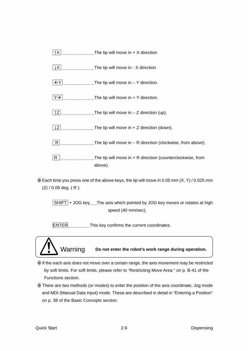
↑X The tip will move in + X direction
↓X The tip will move in - X direction
Y The tip will move in – Y direction.
Y The tip will move in + Y direction.
↑Z The tip will move in – Z direction (up).
↓Z The tip will move in + Z direction (down).
R The tip will move in – R direction (clockwise, from above).
R The tip will move in + R direction (counterclockwise, from
above).
Φ Each time you press one of the above keys, the tip will move in 0.05 mm (X, Y) / 0.025 mm
(Z) / 0.09 deg. ( R ).
SHIFT + JOG key The axis which pointed by JOG key moves or rotates at high
speed (40 mm/sec).
ENTER This key confirms the current coordinates.
Do not enter the robot’s work range during operation. Warning
Φ If the each axis does not move over a certain range, the axis movement may be restricted
by soft limits. For soft limits, please refer to “Restricting Move Area “ on p. B-41 of the
Functions section.
Φ There are two methods (or modes) to enter the position of the axis coordinate; Jog mode
and MDI (Manual Data Input) mode. These are described in detail in “Entering a Position”
on p. 38 of the Basic Concepts section.
Quick Start Dispensing 2-6

2.2.4 Point Type
1) When you input the position coordinates Select Item 1/2 and press ENTER , the Point Type Point Dispense Selection Screen at right will appear. Start of Line Dispense Line Passing
2) Select the type of the point. Arc Point Here, we will use a Point Dispense. End of Line Dispense PTP Evasion Point Point Type Selection Screen, page 1
Enter a number
Dispense Time 0.5 sec
3) Select Point Dispense. You will be prompted to enter the Dispense Time
(see right). Here, we will enter 1 sec as the Dispense Time. Press CLEAR 1 , then press ENTER to
confirm. Dispense Time Entry Screen
4) After the Dispense Time is confirmed, the screen will be ready for entering the next
point. (The point number will be [the current point number + 1].)
Teach Point 0002 according to the settings below. Please refer to “2.2.3 Point Position
Setting” from p. 2-5.
Point Type "PTP Point" is included in "General Job Point".
Point Number Coordinates Point Type
0002 X 20 mm, Y 80mm, Z 30mm, R 0 deg. PTP Point
Quick Start Dispensing 2-7

2. 2. 5 Point Job Number Enter a number. Point Job Number 0 NEW LIST VIEW F.1 F.2 F.3
1) In case of "PTP Point", after selecting the point
type, you are prompted to enter a Point Job Number.
For now, let’s enter the Point Job Number “0”
and press ENTER to confirm. The special number “0” means no point job is
associated with this point.
Point Job Number Entry Screen
Φ For entering numeric values, please refer to “Entering Numeric Values” on p. 36 of the
Basic Concepts section.
Quick Start Dispensing 2-8

2.3 Program Test
After teaching all the points, be sure to test the program.
gPoint running
Press ←DISP key twice to display setting No.3 0001 screen for Point 0001 as shown at right. X+70 Y+120 Z+30 R+0
Point Type Point Dispense Dispense Time 1 sec
When pressing the F.3 key, the point indicated on the screen is carried out, then next point of
setting screen will be displayed. After running the final point, the screen will be changed to a
setting screen for Work Home Position (the waiting point after finishing the running).
Run the points of 0001 and 0002 by pressing the F.3 key to make sure that the robot is
running on the same points as we taught.
Do not enter the robot’s work range during operation. Warning gChecking Data
1) By pressing the MENU key, display the MENU screen. Then, open the second page by
pressing SHIFT + SEL↓ key.
Select Item 1/2 Select Item 2/2 Program Data Setting Test
Point Job Settings Additional Function Data System Settings Sequencer Settings Teaching Data Copy, Delete
Data Save Utility Maintenance Changing Mode
(Menu page 1) (Menu page 2)
Quick Start Dispensing 2-9

2) Select Test, which is the first line on the
second page of the menu. Select Item
The Program Test Screen at right will Checking Data appear. Test Run
3) Checking Data
Select Checking Data on the Program Test screen to check the operation range and
the point type of the taught data.
If no errors are found, the screen will indicate “OK” as the screen at right shows.
No. 3 Checking Data
When an error is found, the screen OK will Indicates a sort of error and point number where the error occurs.
(Checking Data OK screen)
Φ For detailed error information, please refer to “Errors in Point Position” on A-72 and
“Errors in Point Type” on p. A-73 of the Functions section.
gTest Run
If the program data is OK, select Test Run to run the program for one cycle.
If the speed you taught was faster than 250 mm/sec., it will be reduced during the Test
Run for safety. All other conditions will be the same as taught.
When you modify your program, be sure to test it before actually using it.
Do not enter the robot’s work range during operation. Warning
Quick Start Dispensing 2-10

2.4 Running
Now let’s switch to Run mode and run the program we taught.
Turn off the power switch and disconnect the teaching pendant once and turn the power
switch on again. The run mode is set up.
Press the start switch for initialization. Then press the start switch again, the running for
the program will start.
Φ Be sure to carry out a program test before you run a new program.
Φ During the running of the program, when you press the start switch, the robot
stops at the next PTP starting point. When the start switch is pressed again,
the robot will start moving.
Do not enter the robot’s work range during operation. Warning
2.4.1 Emergency Stop The emergency stop function is used when the robot needs to be stopped
immediately due to an unexpected accident while running.
There is an emergency stop button on the robot.
Try running the taught program and hit the Emergency Stop button. The power
source is turned off and the robot is stopped immediately.
Resetting: 1) Turn the Emergency Switch button clockwise to reset it.
2) Press the start switch. Axes are initialized.
3) If teaching pendant is connected, “Teaching Mode” will be set, if not, “Run Mode”
will be set.
Quick Start Dispensing 2-11

2.4.2 I/O Operation
Connect an external switch to the I/O –1 terminals on the backside of the desktop robot
to make External Run Mode. You can start operation by turning on the A01 signal of the
I/O-1 terminal.
(I/O – 1) INPUT
Function Signal Function Signal Start A 01 Program number bit 5 A 09 Free (*) A 02 Program number bit 6 A 10 Program number LOAD A 03 Last Work A 11 Program number bit 0 A 04 Temporary Stop A 12 Program number bit 1 A 05 Busy Signal Operation A 13 Program number bit 2 A 06 Free A 14 Program number bit 3 A 07 Free A 15 Program number bit 4 A 08 Free A 16
OUTPUT
Function Signal Function Signal Ready for start B 01 Dispenser Error B 09 Soft Lock Out B 02 Dispenser ON/OFF B 10 Program Number ACK B 03 Free B 11 Program Number Error B 04 Free B 12 Running B 05 Free B 13 Error B 06 Free B 14 Emergency Stop B 07 Free B 15 Position Error Check B 08 Free B 16
(*) A02 function can be selected from Free/Start Prohibition/Temporary Stop, Start
Prohibition/Move Area Limit/Emergency Stop by System Data Setting.
Φ For detailed information on I/O operation, please refer to “Specifications for I/O-1” on p.
4-1.
Φ A01 and B01 works only on the External Run Mode.
Quick Start Dispensing 2-12
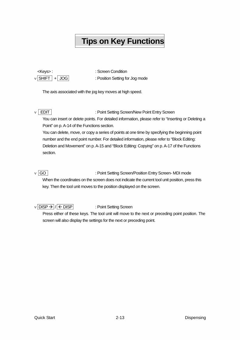
Tips on Key Functions <Keys> : : Screen Condition
ν SHIFT + JOG : Position Setting for Jog mode
The axis associated with the jog key moves at high speed. ν EDIT : Point Setting Screen/New Point Entry Screen
You can insert or delete points. For detailed information, please refer to “Inserting or Deleting a Point” on p. A-14 of the Functions section. You can delete, move, or copy a series of points at one time by specifying the beginning point number and the end point number. For detailed information, please refer to “Block Editing: Deletion and Movement” on p. A-15 and “Block Editing: Copying” on p. A-17 of the Functions section.
ν GO : Point Setting Screen/Position Entry Screen- MDI mode When the coordinates on the screen does not indicate the current tool unit position, press this key. Then the tool unit moves to the position displayed on the screen.
ν DISP / DISP : Point Setting Screen Press either of these keys. The tool unit will move to the next or preceding point position. The screen will also display the settings for the next or preceding point.
Quick Start Dispensing 2-13

3. LET’S OPERATE THE DESKTOP ROBOT (2)
In this section, we will teach and run a program which involves CP movement. The unit tool will run through the five points shown below.
Second Point
Line Passing First Point Start of Line Dispense
Fifth Point End of Line Dispense
Fourth Point Line Passing
Third Point
Arc Point
3. 1 Program Number Setting Here, we will teach a program in an empty program number 04. Select Program 04 from the list of empty program numbers. Please refer to “2.2.1 Program Number Setting” on p. 2-2
3. 2 Modifying Program Data
Change the position coordinates of the Work Home position to the ones below
Point Number Coordinates Work Home Position X 20 mm, Y 20 mm, Z 30 mm, R 0 deg.
Press the MENU key. Select Item 1/2
The screen will display the menu at right. Program Data Settings Point Job Settings Highlight “Program Data Settings” and press Additional Function Data ENTER to confirm. System Settings Sequencer Settings Teaching Data Copy, Delete Menu1
Quick Start Dispensing 3-1

The screen will change to the Program Select Item 1/2
Data Setting Menu at right. Program Name Work Home Select Work Home. Dispense Condition The screen will display the current Work PTP Condition Home position settings. Tool Data Program Data Setting Menu
Select the position coordinates. Work Home X+0 Y+0 Z+0 R+0 The screen will be ready for entering a new Type PTP Point position (in MDI mode). Job Number at Start 0 Job Number at End 0 Work Home Setting Screen
Φ If you need to change the point type of the Work Home, select Type from the screen above.
If you need to change the Job Number at Start or End, select the appropriate line on the same screen.
Enter the new coordinates. Work Home ►X 0.00 mm To enter values, refer to “MDI (Manual Y 0.00 mm Data Input) ” on p. 42 of the Basic Z 0.00 mm Concepts section. R 0.0 deg Input values and press ENTER . JOG MDI INIT The screen will return to the Point Setting Position Setting Screen Screen. Now coordinate change is completed.
Φ On the Position Setting Screen, you can change to the jog mode from the MDI mode. Please refer to the way of changing referring the manual “MDI Mode” on p.42 of the Basic Concept section.
Quick Start Dispensing 3-2

3.3 Point Data Setting
3.3.1 Point Position Setting
Refer to “2.2.3 Point Position Setting” on p. 2-5 to enter the position coordinates for Point 0001. Point Number Coordinates Point Type
0001 X 120mm, Y 150mm, Z 30mm, R 0 deg. Start of Line Dispense 3.3.2 Point Type
1) Input the position coordinates and press Select Item 1/2
ENTER . Point Dispense Line Dispense Start The screen will display a list of point types Line Passing (see right). Arc Point
End of Line Dispense 2) Select the point type (Line Dispense Start, PTP Evasion Point
here). Point Type Screen, page 1
3.3.3 Dispense ON/OFF Setting and Line Speed
Select Item
Dispense ON Dispense OFF
1) If the point type is either Start of Line Dispense or Line Passing, the screen will be prompted to select the Dispense ON/OFF setting (see right).
Highlight Dispense ON and press ENTER to
confirm.
Dispense ON/OFF Selection Screen
2) After selecting the Dispenser ON/OFF setting, you will be prompted to enter the Line Speed (CP Speed). Enter a number. Here, we will enter 40 mm/s as the Line Speed. Line Speed 1 0 mm/s Press CLEAR , then 4 , 0 .
Press ENTER to confirm. Line Speed (CP Speed) Entry Screen
Φ If the point type is Start of Line Dispense or Line Passing, you will be prompted to select the Dispense ON/OFF setting, then enter the Line Speed (CP Speed) after confirming the position
Quick Start Dispensing 3-3

coordinates. When you have confirmed the Line Speed, the screen will be ready for entering the next point. (The Point Number will be [the current Point Number + 1] .)
3) After the Line Speed (CP Speed) is confirmed, the New Point Entry Screen for the next point will
appear. (The Point Number will be [the current Point Number + 1] .) Teach Points 0002 to 0005 according to the settings below. Refer to “2.2.3 Point Position Setting”
on p. 2-5.
Point No. Coordinates Point Type Dispenser ON/OFF
Line Speed
0002 X 120 mm, Y 80 mm, Z 30 mm, R 0 deg. Line Passing ON 40 0003 X 90 mm, Y 20 mm, Z 30 mm, R 0 deg. Arc Point --- 40 0004 X 60 mm, Y 80 mm, Z 30 mm, R 0 deg Line Passing ON 40 0005 X 60 mm, Y 150 mm, Z 30 mm, R 0 deg End of Line Dispense --- ---
Φ The dispenser is automatically turned off at an End of Line Dispense point.
3.4 Program Test, Running When you finish teaching all the points, you are ready to check, and then test the program. Please refer to “2.3 Program Test” on p.2-9 to carry out data check and test run. After the program test, you can actually run the Robot. Please refer to “2.4 Running” on p.2-11.
Warning Do not enter the work range of the robot during operation.
Quick Start Dispensing 3-4

4. SAVING DATA
The following will explain how to save programs and point job data in a memory card. Program data stored in the robot will only be maintained for about 72 hours when the power is turned off. Therefore, you should save the data to a flash memory card, which can keep the data indefinitely (requires no battery). You should save to the memory card not only programs and point job data but all the taught data in the robot, including system data.
No. 4 0001 X+120 Y+150 Z+30 R+0 Type Start of Line Dispense Dispense ON Line Speed 40 mm/s
1) Press SHIFT + ESC to display the Point Setting Screen (see right).
Then press SAVE .
Example of Point Setting Screen (Base Condition)
2) You will be prompted to confirm (see right). All Teaching Data
Select “YES.” Save OK? YES NO
Φ The data in a memory card can be used as backup data in case of a breakdown, power failure,
etc. Be sure to save your data in a memory card after any addition or modification to the taught data.
Φ When the Write Protect Switch of the card is set to Write Protect, you can not save data. When
you want to save the teaching data, set the switch to Write Enable. Please refer to the manual “Releasing the Write Protect” of Basic Concepts on p.14, for more details.
Quick Start Dispensing 4-1

5. TROUBLESHOOTING
5.1 Self Diagnosis Function
If an error occurs during teaching, LCD of teaching pendant will display the error message. If it occurs during running, the robot recognizes the error and stops immediately. The error number will be displayed on the program number display of the front of the robot’s body. Follow the error message to deal with the trouble. If the teaching pendant is not connected to the robot, turn off the power and connect it. When the power is turned on, the screen of the teaching pendant displays the error message. Φ For the description of the errors and remedies, please refer to “Error Messages” on p. 8-1 of the
Specifications section.
5.2 Diagnosis Mode If you suspect a malfunction in the robot, use the diagnosis function to check the operation of each part. The following items are checked in Diagnosis mode.
1. Teaching pendant 8. I/O operation (internal power supply)) 2. Operation Switch 9. I/O operation (external power supply) 3. Buzzers 10. I/O-S 4. DIP switch conditions 11. COM1 (RS232C) communication 5. Initialization sensor condition 12. COM 2 (RS232C) communication 6. Motor driving 7. Initialization sensor position
Φ For detailed information on the diagnosis functions, please refer to “Understanding Problems”
on p. C-17 of the Functions section.
Quick Start Dispensing 5-1

6. MAINTENANCE
Greasing
For smooth operation and long-term use of the robot, apply grease to the machine regularly (approximately every six months).
ν LM (Linear Motion) guide for X axis. (1) Remove the four screws fixing the X cover and
remove it. (Find the screw positions indicated by the arrows in the figure on p.6-3 to 6-5.)
(2) Grease the both sides of the rail surfaces on the LM guide.
LM Guide (Rail)
ν LM (Linear Motion) guide for Y axis (1) Remove the 13 screws fixing Y side cover (Right) and the Y side cover (Left), and remove both covers.
(Find the screw positions indicated by the arrows in the figure on p. 6-3 to 6-5.) (2) Remove the 4 screws, fixing the Y front cover and remove it. (3) Grease both sides of the rail surfaces on the LM guide.
ν Z axis unit (3 axes structure) (1) Remove the 6 screws fixing the Z cover and remove it.
(Find the screw positions indicated by the arrows in the figure on p. 6-3 to 6-5.)
(2)Grease thoroughly on the side of the guide roller touching the Z-axis. (3) Apply the grease on the thread part of the ball thread screw.
Thread part of the ball thread screw
Guide roller
Z axis
Quick Start Dispensing 6-1

■ Z axis unit (4 axes structure) (1) Remove the eight screws of the front and back of the Z covers. Remove the covers.
(Find the screw positions indicated by the arrows in the figure on p. 6-3 to 6-5.) (2) Remove the grease cap screw, and inject the grease into the screw hole. (3) Grease both sides of the rail surfaces on the LM guide. (4) Grease the R-axis (spline shaft ). (5) Apply the grease on the thread part of the ball thread screw.
Be sure to use the grease recoOtherwise malfunction may ens
Recommended grease: AFC G
Quick Start 6-2
Bearing
R axis (Spline shaft) Thread part of the ball thread screwmmue.
rea
LM Guide
ended by the manufacturer.
se by THK Company Ltd.
Dispensing

■The screws to be removed, pointed out by large arrows [ 200 Series ] 4-Axes
RZ cover (Front)
RZ cover (Back)
Y side cover (Left)
Y front cover
X cover
Z cover
Y side cover (Right)
Quick Start Dispensing 6-3

[ 300 Series ]
Y side cover (Right) Y side cover (Left)
Y front cover
X cover
Z cover
4-Axes
RZ cover (Front)
RZ cover (Back)
Quick Start Dispensing 6-4

[ 400 Series ]
Y front cover
4-Axes
RZ cover (Front)
RZ cover (Back)
X cover
Z cover
Y side cover (Right) Y side cover (Left)
Quick St Dispensing art 6-5