Embed Size (px)
Citation preview

Locking Forefoot/Midfoot Plating System

22
Locking Forefoot/Midfoot Plating System
Acumed is an industry leader in innovative solutions for extremities and trauma.
We are dedicated to pioneering solutions that benefit the patient and drive the industry forward.
Innovative Solutions for Forefoot/Midfoot
Designed to address both reconstruction and acute fractures of the forefoot and midfoot, Acumed’s Locking Forefoot/Midfoot System offers indication-specific plates that restore the anatomic geometry of the forefoot and midfoot and also provide Acumed’s innovative locking technology.
Plate options include:
MTP Plates (Available in both 4° and 9° dorsiflexion) - Standard MTP Plate - Dorsal MTP Plate - MTP Revision Plate - Petite MTP Plate (Available in 4° dorsiflexion only)
TMT Plates - 1st Ray TMT Plate - 2nd/3rd Ray TMT Plate - Lapidus Plate - Extended 1st Ray TMT Plate - Extended 2nd/3rd Ray TMT Plate - Extended Lapidus Plate
Osteotomy Plates - Osteotomy Plate - Osteotomy Plate with Compression Slot
The Forefoot/Midfoot System fits conveniently in the Lower Extremity Modular System, which offers a broad range of implants and innovative instrumentation for lower extremity indications.
By designing the Forefoot/Midfoot Tray on the same platform as other Lower Extremity Systems, such as the Locking Ankle and Calcaneal Plate systems, the Forefoot/Midfoot Tray can be used with a modular tray lid for transportability and easy access. Acumed has created a truly modular system that provides the user with multiple solutions.
CONTENTSIntroducing the System 2Locking Forefoot/Midfoot Features 3Small Joint Reamer Features 4Small Joint Reamer Surgical Technique 5Locking MTP Plate Surgical Technique 6Locking Osteotomy Plate Surgical Technique 8Locking TMT Plate
Arthrodesis Procedure Surgical Technique 10Trauma Procedure Surgical Technique 12
Locking Extended TMT PlateTrauma Procedure Surgical Technique 14
Locking Forefoot/Midfoot Instrumentation 17Ordering Information 18

33
TMT Plates
MTP Plates
Osteotomy Plates
4° MTP Plates9° MTP Plates
Locking Forefoot/Midfoot Features
Precontoured Plates match the anatomy of the patient. Based on multiple cadaveric and clinical trials, the MTP plates are precontoured with both 4° and 9° of dorsiflexion and 10° of lateral translation to help restore the functional angle of the MTP joint after fusion.
Multiple Plate Options offer surgeons the best choice in forefoot/midfoot plating from an expanding line of MTP, TMT and Osteotomy plates.
Locking and Nonlocking Screws provide surgeons with the choice of 2.7mm and 3.5mm cortical screws and 4.0mm cancellous screws.
Indications:
• Reconstruction and acute fractures of the foot • Hallux valgus• Proximal osteotomies• Lis Franc injuries
4
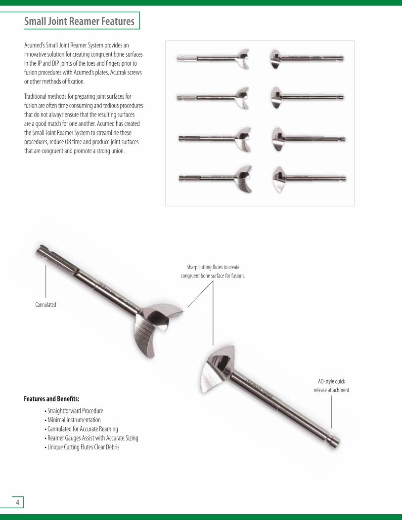
AO-style quick release attachment
Cannulated
Sharp cutting flutes to create congruent bone surface for fusions.
Small Joint Reamer Features
Acumed’s Small Joint Reamer System provides an innovative solution for creating congruent bone surfaces in the IP and DIP joints of the toes and fingers prior to fusion procedures with Acumed’s plates, Acutrak screws or other methods of fixation.
Traditional methods for preparing joint surfaces for fusion are often time consuming and tedious procedures that do not always ensure that the resulting surfaces are a good match for one another. Acumed has created the Small Joint Reamer System to streamline these procedures, reduce OR time and produce joint surfaces that are congruent and promote a strong union.
Features and Benefits:
• Straightforward Procedure• Minimal Instrumentation• Cannulated for Accurate Reaming• Reamer Gauges Assist with Accurate Sizing• Unique Cutting Flutes Clear Debris

5
Small Joint Reamer Surgical Technique
1 Open the joint and fully release the ligaments.
2 Using a K-Wire Driver, insert the .059” or .062” guide wire antegrade down the central axis of the distal phalanx. After placing the appropriate convex reamer over the guide wire, use power to ream the distal fragment until the proximal end
is denuded of cartilage.
3 Insert the second .059” or .062” guide wire retrograde up the proximal phalanx. Insertion should begin at the central axis and travel at the desired angle of flexion. Ream the proximal phalanx over the guide wire using the same size
concave reamer used in Step 2. Ream until the distal end of the phalanx is denuded of cartilage.
4 Fit the phalanges together in the desired flexion and fix with an Acumed MTP or MCP plate, or with an Acutrak screw.

6
Locking MTP Plate
1 Bone Preparation:
Prepare bone surfaces for optimal fusion position. Mark both sides of the joint to establish rotational alignment and flatten the dorsal surface of both the
metatarsal and proximal phalanx.
Note: The MTP plates are precontoured with either a 4° or 9° dorsiflexion and 10° of lateral translation.
2 Metatarsal and Phalangeal Preparation:
Use Acumed’s cannulated Small Joint Reamer System (concave/convex reamers) to denude the cartilage down to bleeding subchondral bone to maximize the
surface contact between the metatarsal head and the proximal phalanx. Alternatively, a burr or rongeur can be used.
3 Plate Placement and Positioning:
Select the appropriate plate for either the left or right foot and for the type of procedure. Secure the plate to the metatarsal with a plate tack (PL-PTACK) driven
through the most proximal hole.
Note: The MTP plates are precontoured to match the anatomy. If bending is required to match specific patient anatomy or other factors, use the plate benders provided (PL-2040 and PL-2045) and bend in one direction only. DO NOT BEND IN BOTH DIRECTIONS. If the locking holes are bent, the locking screws may not lock into the plate.
4 Initial Screw Placement:
Place selected locking drill guide (80-0384 or 80-0385) into the distal hole of the plate and drill through both cortices. Use the depth gauge (MS-9022) to
determine the screw length. Choose the appropriate size screw and insert into the bone. A nonlocking cortical screw can be used initially to pull the plate to the bone.
Note: Select the screw diameter based upon the patient’s bone quality. The 2.0mm drill (80-0386) is used for the 2.7mm screws and the 2.8mm drill (80-0387) is used for the 3.5mm and 4.0mm screws.

7
Surgical Technique
5 Compression of Fusion Site:
Place the gold end of the offset drill guide (PL-2095) into the plate’s compression slot with the arrow on the guide pointing toward the fusion site. Drill and
measure for screw length. Insert the appropriate size nonlocking screw to apply 1mm of compression to the fusion site.
Note: For hard bone, 2.7mm and 3.5mm bone taps (MS-LTT27 and MS-LTT35) are recommended.
6 Insertion of Remaining Screws:
Place selected locking drill guide into the distal medial and lateral holes and drill. Measure and insert locking cortical screws. Remove plate tack from the most
proximal hole and use the same screw insertion process. The nonlocking cortical screw in the distal hole may be replaced with a locking cortical screw at the surgeon’s discretion.
7 Postoperative Protocol:
The foot is protected with a postoperative shoe and dressing. The patient is allowed to proceed with weight-bearing activities as determined by surgeon.

8
Locking Osteotomy Plate
Hallux Valgus Correction
The proximal osteotomy of the first metatarsal is used in conjunction with a distal soft tissue correction of the hallux valgus deformity. It is usually indicated when the first metatarsal and second metatarsal angle is greater than 15°.
1st Metatarsal Osteotomy Exposure
The osteotomy site is exposed through a dorsal incision 1.5” to 2” in length over the dorsum of the base of the first metatarsal. Care is taken to preserve the extensor tendons and small cutaneous nerves and vessels in this area. The periosteum over the base of the first metatarsal is opened and elevated, and the first metatarsal joint is identified.
Osteotomy Procedure
The osteotomy is positioned approximately 1cm distal to the first tarsal-metatarsal (TMT) joint, and is made slightly oblique from perpendicular, to allow more room for the placement of the proximal screws. The concavity of the osteotomy is positioned facing towards the first TMT joint.
Angle Correction
The angle between the first and second metatarsal is decreased with the aid of retractor. The retractor is placed laterally over the proximal fragment pulling the distal end of the proximal fragment into a more medial position while lateral compression is placed across the distal fragment of the first metatarsal. The corrected position of the first metatarsal is then maintained with K-wire fixation as described by James A. Amis, M.D. (Foot and Ankle International, Vol. 20, #11, p.752). An .062” (WS-1607ST) K-wire is placed across the proximal fragment into the medial and middle cuneiform. A second K-wire is placed from the head of the first metatarsal into the second metatarsal. The K-wire fixation allows tentative fixation of this osteotomy so the plate and screws can be attached without having to re-manipulate the osteotomy.
Plate Placement and Positioning
Place the plate, either left or right, over the osteotomy site and secure with a plate tack (PL-PTACK) through the proximal lateral hole.
Note: The 1st Metatarsal Osteotomy plates are precontoured to match the anatomy. If bending is required to match specific patient anatomy or other factors, use the plate benders provided (PL-2040 & PL-2045) and bend in one direction only. DO NOT BEND IN BOTH DIRECTIONS. If the holes are bent, locking screws may not lock into the plate.
1cm
Angle is >15°

9
Surgical Technique
1 Initial Screw Placement:
Place selected locking drill guide (80-0384 or 80-0385) into the proximal medial hole and drill through both cortices. If screw angulation is desired, a standard
drill guide (PL-2118 or PL-2196) can be used to tilt the drill up to 10°. Note that locking cortical screws cannot be used if this procedure is followed. Use the depth gauge (MS-9022) to determine screw length and insert screw.
Note: Select the screw diameter based upon the patient’s bone quality. The 2.0mm drill (80-0386) is used for the 2.7mm screws, and the 2.8mm drill (80-0387) is provided for the 3.5mm and 4.0mm screws.
2 Optional Compression of Osteotomy Site:
Without using the drill guide, place the drill at the distal end of the most distal screw hole. As the nonlocking screw head makes contact with the plate, the
distal fragment will be drawn towards the proximal fragment causing minor interfragmental compression. Otherwise, place selected locking drill guide into the most distal screw hole and use the same screw insertion process.
Note: For hard bone, 2.7mm and 3.5mm bone taps (MS-LTT27 & MS-LTT35) are recommended.
3 Insert Remaining Plate Screws:
Place selected locking drill guide into the second most distal hole and drill. Measure and insert locking cortical screws. Remove plate tack from the proximal
lateral hole and use the same screw insertion process. Finally, the nonlocking cortical screw in the proximal medial hole may be replaced with a locking cortical screw at the surgeon’s discretion.
4 Optional Bone Graft for Osteotomy Site:
The wound is irrigated. Bone graft material can be used for the distal soft tissue procedure from the excised medial extosis. This is usually placed at the lateral
aspect of the osteotomy. The wound is then closed with appropriate closure.
5 Postoperative Protocol:
The foot is protected with a post-op shoe and dressing. The patient is allowed to proceed with weight-bearing activities as determined by surgeon.

10
Locking TMT Plate Arthrodesis Procedure
1 Exposure:
The first TMT joint is exposed through a medial incision. Carry dissection down to expose the anterior tibialis tendon, which is protected. A portion of the tendon
may need to be elevated from the medial cuneiform and metatarsal; however, this should be minimized. The joint is exposed medially then dorsally and plantarly, carefully avoiding the extensor hallux longus tendon at the dorsal aspect of the joint.
Note: Image intensification is recommended during this procedure to confirm reduction and placement of hardware.
2 TMT Joint Preparation:
Gain access to the first TMT joint and perform joint preparation in the standard fashion with thorough removal of all articular cartilage and preparation of
subchondral bone. Confirm the correct positioning of the metatarsal and cuneiform, and provisionally fix the joints involved with K-wires placed superiorly and inferiorly to allow for the plate.
Note: If interfragmentary lag screw fixation is desired to supplement the plate, it should be placed first, and typically oriented from the plantar aspect of the metatarsal base proximally into the medial cuneiform, as the plate sits dorso-medially. Lag screw fixation may also occur through the plate’s slot.
3 Plate Placement and Positioning:
Apply the plate to the dorsal medial aspect of the TMT joint and secure with a plate tack (PL-PTACK) or .062” K-wire (WS-1607ST) through the distal K-wire hole.
Note: The TMT plates are precontoured to match the anatomy. If bending is required to match specific patient anatomy or other factors, use the plate benders provided (PL-2040 & PL-2045) and bend in one direction only. DO NOT BEND IN BOTH DIRECTIONS.
4 Initial Screw Placement:
Insert screw - the initial screw should be nonlocking and is typically placed in distal cuneiform hole as shown. According to the surgeon’s preference, the screw
can be placed across one, two or all three cuneiforms for stability. Use the depth gauge (MS-9022) to determine screw length. Choose the appropriate size screw and insert into the bone.
Note: Select the screw diameter based upon the patient’s bone size. The 2.0mm drill (80-0386) is used for the 2.7mm screws, and the 2.8mm drill (80-0387) is provided for the 3.5mm and 4.0mm screws. If a lag screw is used through the plate, it should be placed first and placed through the oval metatarsal hole.

11
Surgical Technique By Douglas N. Beaman, M.D.
5 Compress Fusion Site:
Place the gold end of the offset drill guide (PL-2095) into the plate’s compression slot with the arrow on the guide pointing toward the fusion site.
Drill and measure for screw length. Insert appropriate size nonlocking screw to apply 1mm of compression to the fusion site.
6 Insert Remaining Screws:
Remove the plate tack from the distal K-wire hole. Place selected locking drill guide into the distal metatarsal hole and drill if locking screw is desired. Measure
and insert locking cortical screws. Follow the same process for the proximal cuneiform hole. Following irrigation, close the wound with a nylon suture or per surgeon preference.
Note: For additional fixation, a longer cortical screw may be used to cross into the other cuneiforms. This may also stabilize intercuneiform fusions
7 Postoperative Protocol:
The foot is placed in a neutral plantigrade position with a well-padded dressing incorporating below-knee plaster splints.This is typically changed at 7-14 days,
with sutures removed after 10-14 days or once wound healing is complete. For reconstructive purposes, a short leg, non-weight-bearing cast is then applied for an additional four weeks for a total non-weight-bearing period of six weeks. If there is evidence of union based on plain radiographs, weight-bearing is initiated at this time in a short-leg walking cast.

12
Locking TMT Plate Trauma Procedure
1 Exposure:
The first TMT joint is exposed through a medial incision. Carry dissection down to expose the anterior tibialis tendon, which is protected. A portion of the tendon
may need to be elevated from the medial cuneiform and metatarsal; however, this should be minimized. The joint is exposed medially then dorsally and plantarly, carefully avoiding the extensor hallux longus tendon at the dorsal aspect of the joint.
Note: Image intensification is recommended during this procedure to confirm reduction and placement of hardware.
2 TMT Joint Preparation:
Reduce joint by aligning anatomic landmarks and fix provisionally with .045” K-wires (WS-1106ST) placed superiorly and inferiorly across the joint to allow
room for the plate.
Note: Definitive fracture stabilization of intra-articular fragments can be performed with intrafragmentary screw fixation.
3 Plate Placement and Positioning:
Apply the plate to the dorsal medial aspect of the TMT joint, and secure with a plate tack (PL-PTACK) or .062” K-wire through the distal K-wire hole.
Note: The TMT plates are precontoured to match the anatomy. If bending is required to match specific patient anatomy or other factors, use the plate benders provided (PL-2040 & PL-2045) and bend in one direction only. DO NOT BEND IN BOTH DIRECTIONS.
4 Initial Screw Placement:
Place selected drill guide (80-0384 or 80-0385) into the distal medial cuneiform hole and drill to engage either the second metatarsal bone or medial cuneiform.
This may be placed in a lag fashion, depending on injury pattern. A separate incision may be needed to expose and reduce the 2nd TMT joint or inter-cuneiform joints prior to placement of this first screw. Use the depth gauge (MS-9022) to determine screw length. Choose the appropriate screw and insert into the bone.
Note: Select the screw diameter based upon the patient’s bone size and/or fracture pattern. The 2.0mm drill (80-0386) is used for the 2.7mm screws, and the 2.8mm drill (80-0387) is provided for the 3.5mm and the 4.0mm screws.

13
Surgical Technique By Douglas N. Beaman, M.D.
5 Trauma Stabilization:
Place the green end of the offset drill guide (PL-2095) into the compression slot of the plate to drill the hole neutral. The second metatarsal bone can be engaged
if necessary for additional stabilization. Use the depth gauge and insert the appropriate size screw.
6 Insert Remaining Screws:
Remove the plate tack from the distal K-wire hole. Place selected locking drill guide into the distal metatarsal hole and drill, if a locking screw is desired.
Measure and insert locking cortical screws. Follow the same process for the proximal cuneiform hole. Following irrigation, close the wound with nylon suture or surgeon’s preference. Locking or nonlocking screws may be used dependent on bone quality and injury pattern.
Note: For additional fixation, a longer cortical screw may be used to cross into the other cuneiforms. This may also stabilize any intercuneiform disruptions.
7 Postoperative Protocol:
The foot is placed in a neutral plantigrade position with a well-padded dressing incorporating below-knee plaster splints. This is typically changed at seven to
fourteen days, with sutures removed after ten to fourteen days or once wound healing is complete. For trauma applications, the patient is advanced to a removable boot at approximately two weeks post-op to allow ankle and hindfoot motion. Weight-bearing is protected for eight to twelve weeks in trauma applications depending upon particular injury pattern.

14
Locking Extended TMT Plate Trauma Procedure
1 Exposure:
The first TMT joint is exposed through a medial incision. Carry dissection down to expose the anterior tibialis tendon, which is protected. A portion of the tendon
may need to be elevated from the medial cuneiform and metatarsal; however, this should be minimized. The joint is exposed medially then dorsally and plantarly, carefully avoiding the extensor hallux longus tendon at the dorsal aspect of the joint. The incision may be extended proximally and distally to expose fractures.
Note: Image intensification is recommended during this procedure to confirm reduction and placement of hardware.
2 TMT Joint Preparation and Distal Fracture Stabilization:
Reduce joint by aligning anatomic landmarks and fix provisionally with .045” K-wires (WS-1106ST) placed superiorly and inferiorly across the joint to allow
room for the plate. Reduce metatarsal fractures and provisionally stabilize with clamps and/or K-wires.
Note: Definitive fracture stabilization of intra-articular fragments can be performed with interfragmentary screw fixation. Distal extra-articular fractures may also be fixed with lag screws depending on fracture pattern.
3 Plate Placement and Positioning:
Apply the plate to the dorsal medial aspect of the TMT joint, and secure with a plate tack (PL-PTACK) or .062” K-wire through the distal K-wire hole.
Note: The TMT plates are precontoured to match the anatomy. If bending is required to match specific patient anatomy or other factors, use the plate benders provided (PL-2040 & PL-2045) and bend in one direction only. DO NOT BEND IN BOTH DIRECTIONS.
4 Initial Screw Placement:
Place selected drill guide (MS-LDG27 or MS-LDG35) into the distal medial cuneiform hole and drill to engage the second metatarsal bone or medial
cuneiform, depending on injury pattern. A separate incision may be needed to expose and reduce the 2nd TMT joint or inter-cuneiform joints prior to placement of this first screw. This may be placed in a lag fashion. Use the depth gauge (MS-9022) to determine screw length. Choose the appropriate screw and insert into the bone.
Note: Select the screw diameter based upon the patient’s bone size and fracture pattern.The 2.0mm drill (MS-DC5020) is used for the 2.7mm screws, and the 2.8mm drill (MS-DC28) is provided for the 3.5mm and the 4.0mm screws.

15
Surgical Technique By Douglas N. Beaman, M.D.
5 Trauma Stabilization:
Place the green end of the offset drill guide (PL-2095) into the compression slot of the plate to drill the hole neutral. The second metatarsal bone can be engaged
if necessary for additional stabilization. Use the depth gauge and insert the appropriate size screw.
6 Insert Screws:
Remove the plate tack from the distal K-wire hole. Place selected locking drill guide into the distal metatarsal hole and drill if a locking screw is desired.
Measure and insert locking cortical screws. Follow the same process for the proximal cuneiform hole. Locking or nonlocking screws may be used depending on bone quality and injury pattern.
Note: For additional fixation, a longer cortical screw may be used to cross into the other cuneiforms. This may also stabilize any intercuneiform disruptions.
7 Distal Fracture Stabilization:
Once the proximal screws on either side of the TMT joint have been installed, the distal metatarsal fracture alignment may be adjusted, if necessary, and clamped
to ensure proper plate alignment.
8 Screw Placement on Distal End of Fracture:
Place selected drill guide into desired screw location and drill through both cortices of the metatarsal. Measure and insert screw. Depending on fracture
reduction/pattern and plate position on bone, a locking or nonlocking initial screw is placed.
Note: It may be possible to place a lag screw across the fracture and through the plate if the fracture pattern will allow.

16
Locking Extended TMT Plate Trauma Procedure
9 Insert Remaining Screw:
If a locking screw is desired, place selected locking drill guide into the remaining holes and drill. Measure and insert remaining locking screws. Following
irrigation, close the wound with nylon suture or surgeon’s preference.
Note: Depending on the proximity of the most distal plate hole, to the metatarsal phalangeal joint, it may be necessary to angle the screw away from the joint using the nonlocking drill guide and a cortical screw.
10 Postoperative Protocol:
The foot is placed in a neutral plantigrade position with a well-padded dressing incorporating below-knee plaster splints. This is typically changed
at seven to fourteen days, with sutures removed after ten to fourteen days or once wound healing is complete. For trauma applications, the patient is advanced to a removable boot at approximately two weeks post-op to allow ankle and hindfoot motion. Weight-bearing is protected for eight to twelve weeks in trauma applications depending upon particular injury pattern.

17
Instrumentation
Lower Extremity Modular System
The Lower Extremity Modular System offers instrumentation chosen by surgeons for lower extremity indications. It includes an improved screw caddy, locking drill guides and an extensive array of lower extremity instrumentation that makes the system easy to use.
4° Locking MTP Plates 9° Locking MTP Plates
Reamers with Quick Release
Osteotomy Plates with Compression Slot
Osteotomy Plates
TMT Plates

18
Ordering Information
Forefoot/Midfoot Plates
Locking Dorsal MTP Plate L 70-0141
Locking Dorsal MTP Plate R 70-0142
Locking Dorsal MTP Fusion Plate, L 70-0012
Right Locking Dorsal 1st MTP Fusion Plate 70-0013
Locking MTP Revision Plate L 70-0143
Locking MTP Revision Plate R 70-0144
Left Locking 1st MTP Revision Fusion Plate 70-0018
Right Locking 1st MTP Revision Fusion Plate 70-0019
Locking MTP/MPJ Combo Plate 4 Degree Left 70-0109
Locking MTP/MPJ Combo Plate 4 Degree Right 70-0110
Left Locking 1st MTP/MPJ Combo Fusion Plate 70-0036
Right Locking 1St MTP/MPJ Combo Fusion Plate 70-0037
Locking MTP Petite Plate 4 Degree, Left 70-0329
Locking MTP Petite Plate 4 Degree, Right 70-0330
5 Hole Locking 1st Tarsometatarsal Plate 70-0007
4 Hole Locking 1st Tarsometatarsal Plate 70-0008
4 Hole Locking 2nd And 3rd Tarsometatarsal Plate 70-0009
8 Hole Locking 1st Tarsometatarsal Plate 70-0049
7 Hole Locking 1st Tarsometatarsal Plate 70-0050
7 Hole Locking 2nd & 3rd Tarsometatarsal Plate 70-0051
Left Locking Proximal Metatarsal Wedge Plate 70-0010
Right Locking Proximal Metatarsal Wedge Plate 70-0011
MT Wedge Plate, 0 Degree, L 70-0323
MT Wedge Plate, 0 Degree, R 70-0324
Reamers
16mm MTP Reamer Concave 80-0569
16mm MTP Reamer Convex 80-0570
18mm MTP Reamer Concave 80-0571
18mm MTP Reamer Convex 80-0572
20mm MTP Reamer Concave 80-0573
20mm MTP Reamer Convex 80-0574
22mm MTP Reamer Concave 80-0575
22mm MTP Reamer Convex 80-0576
Instrumentation
2.8mm Locking Drill Guide 6-65mm 80-0384
2.0mm Locking Drill Guide 6-65mm 80-0385
2.0mm Quick Release Drill 80-0386
2.8mm Quick Release Drill 80-0387
Small Ratchet Handle with Quick Release Connection 80-0398
2.5mm Quick Release Hex Driver HPC-0025
2.5mm Solid, Quick Release, Driver Tip HT-2502
6mm-70mm Depth Gauge, 2mm Increments MS-9022
3.5mm x 5” Quick Release Drill MS-DC35
2.7mm Cortical Screw Bone Tap MS-LTT27
3.5mm Cortical Screw Bone Tap MS-LTT35
3.5mm Screw Driver Sleeve MS-SS35
Plate Bender PL-2040
Plate Bender, Large PL-2045
Cortical and Cancellous Screw Countersink PL-2080
Offset Drill Guide PL-2095
2.0mm / 2.8mm Thin Drill Guide PL-2118
2.8mm / 3.5mm Thin Drill Guide PL-2196
Plate Tack PL-PTACK
.045” X 6” ST Guide Wire WS-1106ST
.062” x 6” Guide Wire WS-1607ST
Soft Tissue Instrument Tray
8” Bone Reduction Forceps MS-1280
Bone Reduction Forceps, 5.25” MS-45300
Periosteal Elevator, 7.25” MS-46211
15mm Hohmann Retractor MS-46827
Bone Reduction Forceps with Points, 5 Broad MS-47135
Inge Retractor, 6.5” MS-48217
Needle Nose Pliers, 5.5” MS-48245
Freer Elevator, 7.5” MS-57614
Small Pointed Reduction Forceps OW-1200
Reduction Forceps with Serrated Jaw PL-CL04
8mm Hohmann Retractor PL-CL05
Sharp Hook PL-CL06

19
Ordering Information
The Locking Forefoot/Midfoot Plating System may also be used in combination with the following Acumed Products:
• Acutrak 2® - 5.5• Acutrak 2® Standard, Micro and Mini• AcuTwist® Compression Screws• Extremity Screws
For ordering information, please contact your local Acumed® Sales Representative.
Optional Instruments
Inge Retractor without Teeth 80-0472
Large Cannulated Quick Release Driver Handle MS-3200
Plate Holder Assembly PL-2030
Tray Components
Forefoot/Midfoot System Tray Assembly 80-0589
Forefoot/Midfoot System Tray Base 80-0590
Lower Extremity Tray Lid 80-0431
Lower Extremity Modular System Screw Caddy 80-0430