Embed Size (px)
Citation preview
LRMS Manual Effective from: July 2004 Manual No. SM051 B-1
PART B: LOCATION REFERENCING METHOD
P ART B:
LOCATION REFERENCING METHOD

LRMS Manual Effective from: July 2004 Manual No. SM051 B-2
RECORDING A ROUTE POSITION Overview This chapter explains how the location referencing signs, described
in Chapter 3, are used to determine a location on the network, i.e. the route position. The method of recording a route position varies slightly depending on whether you are on: a typical section of highway (95% of the network), an ON or OFF ramp, or a divided carriageway (central median or different roads), or a large roundabout
In this Chapter The topics in this chapter are listed below: Topic Page
Highway Direction B – 3 Signs Overview B – 4 On a Typical Highway B – 4 On a Large Roundabout B – 6 On a Divided Highway B – 8 On a Ramp B – 10

LRMS Manual Effective from: July 2004 Manual No. SM051 B-3
2.1 Highway Direction Cardinal Highway Direction
Each state highway has increasing direction as indicated in Figure 0.1 below. The increasing direction of travel is the direction in which positive measurements are made.
Figure 0.1 State Highway Increasing Direction Confirmation of Increasing Direction
Not all highways comply with the general rules above. There are a number of ways to confirm the direction of positive measurement (increasing direction). When travelling on a highway in the increasing direction: (a) signs will appear on the “true” left side of the road (except for
divided carriageways) (b) the displacements on two consecutive signs will increase and (c) the orange arrows on the side of location referencing signs will
point in the highway’s increasing direction, Figure 2.2.
Figure 0.2 Arrow Indicating Increasing Direction

LRMS Manual Effective from: July 2004 Manual No. SM051 B-4
2.2 Signs Overview General Signs along the highway help you to identify and measure route
positions accurately. A green band on a sign indicates that the sign is accurately placed and can be used for measurement. The complete specifications for location referencing signs are given in Chapter 3 however to assist with the understanding of recording a route position, the three most common signs are introduced below.
Reference Stations
Reference stations (RS) are primary points for measurement. They are generally located at 16 km intervals and once placed do not change. Measurement must start from 0m at every RS. A yellow square on the road marks the exact location from which to measure. The sign pictured indicates that you are on State Highway 1, at RS number 262.
Established Route Positions
Established route positions (ERP) are placed at 3 – 5 km intervals between RS. They assist in taking measurements between Reference Stations. Each ERP sign displays the previous RS number, and a measurement from the RS. This sign indicates that you are 3 kilometres past RS 262.
Kilometre Marker Posts
Kilometre marker posts (KMP) are placed at approximately 1 km intervals. A black band indicates that a KMP is a proximity flag only, and cannot be used for accurate measurements. This sign indicates that you are approximately 12 km past RS 262.

LRMS Manual Effective from: July 2004 Manual No. SM051 B-5
2.3 On a Typical Highway On a Typical Highway To measure a route position on a typical highway, users will start at
the preceding reference station (RS) yellow square or established route position (ERP) sign and record the distance to the object from the yellow square or sign in the format shown in the following example. Figure 0.3 below shows a truck which is at the unique route position 01N-0262/1.70 where: 01N = State Highway 1, North Island1 0262 = Reference Station Number2 1.70 = Truck Location (1.70km past the RS)3
Notes: 1. The SH reference is always 3 characters. In the case of SH 1
that runs the length of the country, the last character denotes the island (‘N’orth or ‘S’outh). For all other highways, zeros are used to pad the reference to three characters e.g. SH 6 would be recorded as 006, SH 20A as 20A, SH 6B as 06B etc.
2. The RS reference is always 4 characters. 3. The distance of the item past the RS should be recorded to two
decimal places. Note that measurements on a typical highway are never to be taken while driving in the decreasing direction.
Figure 0.3 On a Typical Highway
LRMS Manual Effective from: July 2004 Manual No. SM051 B-6
2.4 On a Large Roundabout Large Roundabouts In general where a roundabout has a circumference greater than 150
metres it is referenced as a separate road section. At less than 150 metres traversing a roundabout at the correct speed for high-speed data collection may not be possible. These roundabouts have a unique reference or name derived from the running distance along the highway followed by a ‘W’, for example roundabout 700-W is approximately 3km from RS 697 on SH 1. State highway surveys are broken at these roundabouts. ERP signs indicate where the state highway survey ends and starts again. All referencing on the roundabout is measured from the yellow square indicating the ‘true’ location of the roundabout reference station, in the direction of travel along the inside lane. See the next page for an example

LRMS Manual Effective from: July 2004 Manual No. SM051 B-7
The route position of the dig out on the roundabout in
Figure 0.4 is 01N-0700-W/0.10 where: 01N = SH1, North Island 0700-W = Roundabout Number 0.10 = Dig out Location. When back on the state highway the route positions are again referenced back to the preceding RS, the measurement being taken from the ERP sign at the exit to the roundabout. For example in Figure 0.4 the route position of the first cone after the roundabout is 01N-0697/3.10 where: 01N = SH1, North Island 0697 = RS 3.10 = First Cone Location (measured in the field as 0.04km past ERP 697/3.06).
Figure 0.4 On a Large Roundabout
LRMS Manual Effective from: July 2004 Manual No. SM051 B-8
2.5 On a Divided Highway Divided Carriageways Divided carriageways follow separate alignments (i.e. the
carriageways are different lengths) or are physically separated by a median with a length greater than 300 metres. The start and end of the divided carriageways are marked with RS’s or ERP’s, see Section 3.3 and 3.7 for when each is used. When referring to a particular side of a divided carriageway an identifier is used. The convention for this identifier is based on the state highway direction as shown in Figure 0.1, where: ‘I’ is used as to indicate the increasing direction or the side
where the traffic flow is in the same direction as the highway. ‘D’ is used for the decreasing direction where traffic flow and
measurement is done in the opposite direction to that of the highway.
On the increasing side the measurements are made as normal from the preceding RS or ERP with the addition of the identifier ‘I’ as shown in the following example. The surface flooding in Figure 0.5 runs from route position 01N-0656/10.00-I to 01N-0656/10.50-I where: 01N = SH1, North Island 0656 = RS 10.00 = Start position of surface flooding (1.50km from ERP 656/8.50-I) 10.50 = End position of surface flooding (2.00km from ERP 656/8.50-I) I = Increasing Carriageway The decreasing direction of a divided carriageway is the only instance when measurements are to be made in the direction opposite to the direction of the highway. In this case, the measurement is made from the RS or ERP located at the end of the divided carriageway section and the distance measured is subtracted from the distance indicated on the sign. For example, the route position of the two way traffic road signs in Figure 0.5 is 01N-0656/9.00-D where: 01N = SH1, North Island 0656 = RS 9.00 = Two Way Traffic Road Signs ( - 2.20km from ERP 656/11.20-D) D = Decreasing Carriageway Note that once the divided carriageway section has returned to a single carriageway, measurements are only made from the signs on the increasing direction.

LRMS Manual Effective from: July 2004 Manual No. SM051 B-9
Figure 0.5 On a Divided Highway
LRMS Manual Effective from: July 2004 Manual No. SM051 B-10
2.6 On Ramps On and Off Ramps All On or Off Ramps connecting the highway are grouped and
referenced to a unique interchange number. Ramps are generally numbered in a clockwise direction around the interchange, based on the location of the start of the ramp. Ramps are referenced as a separate road with positive displacements measured in the direction of traffic flow. Therefore, measurements on an on ramp will start at the RS on the boundary of the local road and end where it intersects with the highway. The ramp generally begins and ends where a full lane width of 3.5 metres is reached or lost. The authoritative location for the start of measurement is the yellow square. The route position of the accident in Figure 0.6 is: 006-0172-R1/0.15, where: 006 = SH6, South Island 0172 = Interchange Number R1 = Ramp Number 0.15 = Accident Location (0.15km from off Ramp RS).
Interchange Number An interchange is a cluster of ramps. Interchanges are numbered
based on a linear distance (in the positive direction) from the previous RS to centre of the interchange, (rounded to the nearest kilometre). The centre of the interchange in Figure 0.6 lies on SH 6, approximately 5.20 km from RS 0167 hence the interchange number is given the number of 0172.

LRMS Manual Effective from: July 2004 Manual No. SM051 B-11
Figure 0.6 Off and On Ramps
LRMS Manual Effective from: July 2004 Manual No. SM051 B-12
3 SIGN DESIGN AND PLACEMENT
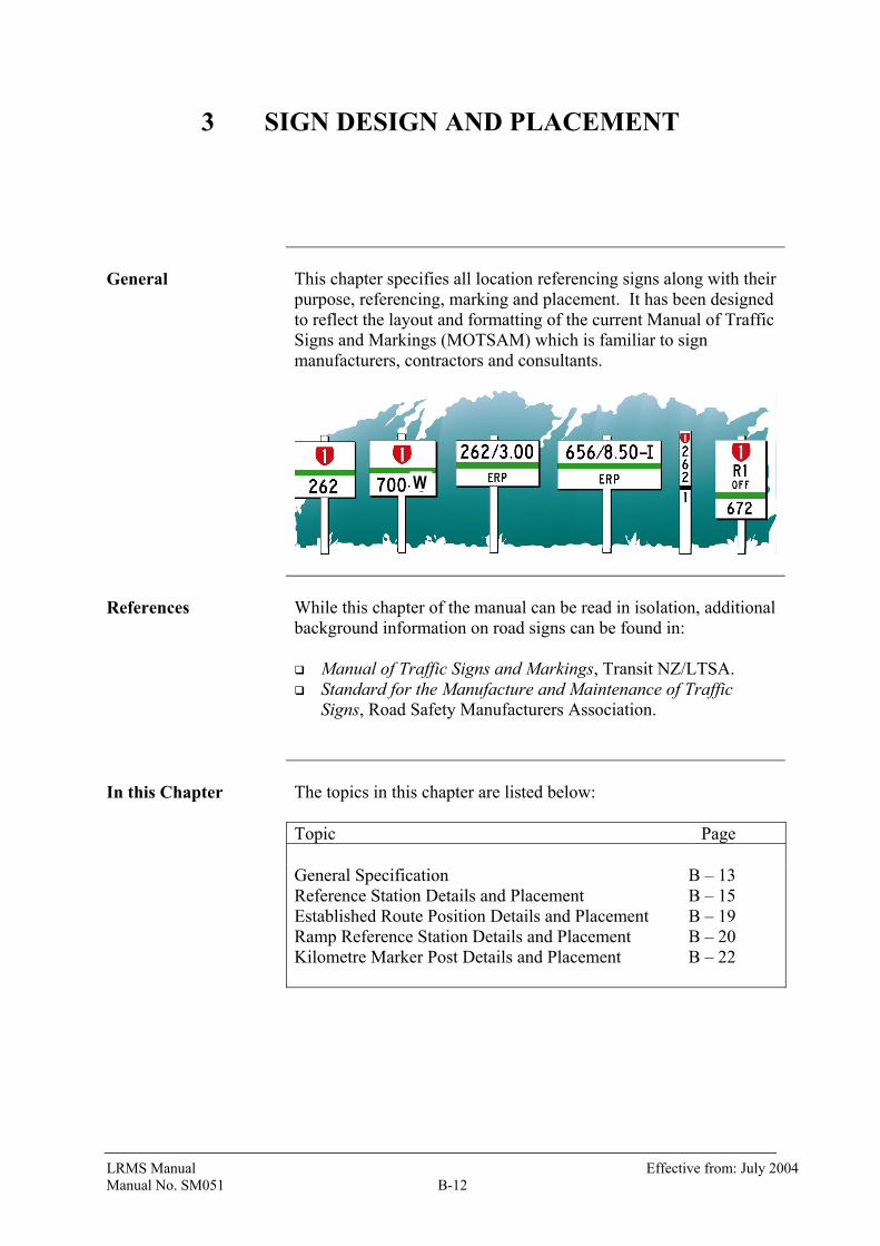
General This chapter specifies all location referencing signs along with their
purpose, referencing, marking and placement. It has been designed to reflect the layout and formatting of the current Manual of Traffic Signs and Markings (MOTSAM) which is familiar to sign manufacturers, contractors and consultants.
References While this chapter of the manual can be read in isolation, additional
background information on road signs can be found in: Manual of Traffic Signs and Markings, Transit NZ/LTSA. Standard for the Manufacture and Maintenance of Traffic
Signs, Road Safety Manufacturers Association.
In this Chapter The topics in this chapter are listed below: Topic Page General Specification B – 13
Reference Station Details and Placement B – 15 Established Route Position Details and Placement B – 19 Ramp Reference Station Details and Placement B – 20 Kilometre Marker Post Details and Placement B – 22
W

LRMS Manual Effective from: July 2004 Manual No. SM051 B-13
3.1 General Specification
LR Type ‘A’ LEGEND : black : 75mm or 50mm series C BACKGROUND : non-reflectorised white SH SHIELD : white number on red (if specified) STRIP : reflectorised green
LR Type ‘B’
LEGEND : black : 75mm or 50mm series C BACKGROUND : non-reflectorised white SH SHIELD : white number on red STRIP : reflectorised black
GENERAL SPECIFICATION: Type ‘A’ location referencing (LR) signs include: Reference Stations Established Route Positions, Ramp Reference Stations and Roundabout Reference Stations signs.
Type ‘A’ Specification: The main component of Type ‘A’ location referencing signs is a rectangular shaped sign plate with a 25 mm green band. The sign plate varies in size depending on the subtype and text displayed. Type ‘A’ sign plates and posts shall comply with the physical requirements of the materials specification in the Road Safety Manufacturers Association Standard for the Manufacture and Maintenance of Traffic Signs. An acceptable solution would be: 2mm thick grade NS4 (5251-H34) aluminium, Powder coated (non-reflective), and fitted to a 100x100 Class H4 treated timber post, primed and
finished with high gloss white paint. Type ‘B’ Specification: Type ‘B’ location referencing signs or Kilometre Marker Posts (KMP) are to comply with the physical requirements of the edge marker post specification (TNZ M/14).
Dimension: Refer detail section for the physical dimensions of each sign type. Double Sided: Type ‘A’ signs shall generally comprise two plates used back to back on a post on the left-hand side of the highway as viewed from a vehicle travelling in the increasing direction. Signs shall be mounted with the plates oriented at right angles to the road centreline and shall be conspicuously sited. The exceptions are: Ramps, Roundabouts and RS and ERP signs on divided carriageways.
In these situations signs consist of a single plate facing in the direction of approaching vehicles. Type ‘B’ signs shall be marked with the required shield and lettering on both sides of the post. The exception is where the signs are placed on divided carriageways where they shall be single sided (as they do not have to be read while travelling along the opposing carriageway).
LRMS Manual Effective from: July 2004 Manual No. SM051 B-14
LETTERING: Size and Shape: All letters and numerals shall comply with the Series C UPPERCASE font set specified AS1744-1975 or in the Transit New Zealand Manual of Traffic Signs and Markings, generally with letters 50 mm in height and numerals 75 mm in height (refer detail). Colouring: Three colours are used for standard lettering and shields on LR signs. Samples of these colours are available for comparative purposes through Standards New Zealand. Red: Signal Red (no.537) as defined in
NZS7702:1989 White: White (N14) as defined in AS2700S:1996 Black: Black Retro-reflective Green/Black: Class 2 sheeting
complying with AS/NZS 1906.1: 1993, Table 2.3. PLACEMENT: Spatial Accuracy of RS: RS are a benchmark marked primarily by a yellow square and also by a sign. The yellow square marks the “true” position for the start of measurement at all reference stations (including ramps and large roundabouts) and shall have a spatial position recorded in terms of the NZMG co-ordinate system (NZGD1949). The recorded co-ordinate is to be within ± 3m of the actual spatial position. The RS signs are required to be placed adjacent to the yellow square. Linear Accuracy: ERP signs are required to be placed to a linear accuracy of within ± 0.1% of their actual displacement from the reference station as per Section 5.2.1. Type ‘B’ signs are required to be placed to an accuracy of within ± 100m of their actual displacement. Lateral Offset: LR signs are to be placed at a consistent offset in accordance with the requirements as tabulated below. This specification should result in LR signs being generally placed at a 1m greater offset than the surrounding edge marker posts.
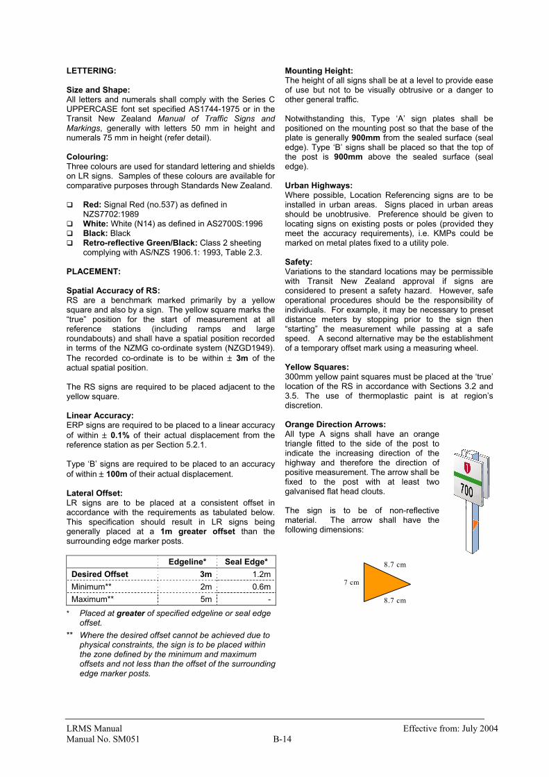
Mounting Height: The height of all signs shall be at a level to provide ease of use but not to be visually obtrusive or a danger to other general traffic. Notwithstanding this, Type ‘A’ sign plates shall be positioned on the mounting post so that the base of the plate is generally 900mm from the sealed surface (seal edge). Type ‘B’ signs shall be placed so that the top of the post is 900mm above the sealed surface (seal edge). Urban Highways: Where possible, Location Referencing signs are to be installed in urban areas. Signs placed in urban areas should be unobtrusive. Preference should be given to locating signs on existing posts or poles (provided they meet the accuracy requirements), i.e. KMPs could be marked on metal plates fixed to a utility pole. Safety: Variations to the standard locations may be permissible with Transit New Zealand approval if signs are considered to present a safety hazard. However, safe operational procedures should be the responsibility of individuals. For example, it may be necessary to preset distance meters by stopping prior to the sign then “starting” the measurement while passing at a safe speed. A second alternative may be the establishment of a temporary offset mark using a measuring wheel. Yellow Squares: 300mm yellow paint squares must be placed at the ‘true’ location of the RS in accordance with Sections 3.2 and 3.5. The use of thermoplastic paint is at region’s discretion. Orange Direction Arrows: All type A signs shall have an orange triangle fitted to the side of the post to indicate the increasing direction of the highway and therefore the direction of positive measurement. The arrow shall be fixed to the post with at least two galvanised flat head clouts. The sign is to be of non-reflective material. The arrow shall have the following dimensions:
Edgeline* Seal Edge* Desired Offset 3m 1.2m Minimum** 2m 0.6m Maximum** 5m -
* Placed at greater of specified edgeline or seal edge offset.
** Where the desired offset cannot be achieved due to physical constraints, the sign is to be placed within the zone defined by the minimum and maximum offsets and not less than the offset of the surrounding edge marker posts.
8.7 cm
8.7 cm
7 cm
LRMS Manual Effective from: July 2004 Manual No. SM051 B-15
3.2 Reference Station Sign Details
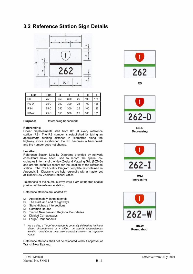
Sign Text a b c d e RS 75 C 350 300 25 100 125 RS-D 75 C 350 300 25 100 125 RS-I 75 C 350 300 25 100 125 RS-W 75 C 350 300 25 100 125 Purpose: Referencing benchmark Referencing: Linear displacements start from 0m at every reference station (RS). The RS number is established by taking an approximate running distance in kilometres along the highway. Once established the RS becomes a benchmark and the number does not change. Location: Reference Station Locality Diagrams provided by network consultants have been used to record the spatial co-ordinates in terms of the New Zealand Mapping Grid (NZMG) and are the definitive record for the location of the reference station. The RS Locality Diagram template is contained in Appendix B. Diagrams are held regionally with a master set at Transit New Zealand National Office. Tolerances of the NZMG survey were ± 3m of the true spatial position of the reference station. Reference stations are located at: Approximately 16km intervals The start /and end of highways State Highway Intersections Common Routes Transit New Zealand Regional Boundaries Divided Carriageways Large1 Roundabouts
1. As a guide, a “large” roundabout is generally defined as having a
driven circumference of > 150m. In special circumstances smaller roundabouts may also warrant treatment as separate roads.
Reference stations shall not be relocated without approval of Transit New Zealand.
RS
RS-D Decreasing
RS-I Increasing
RS-W Roundabout
LRMS Manual Effective from: July 2004 Manual No. SM051 B-16
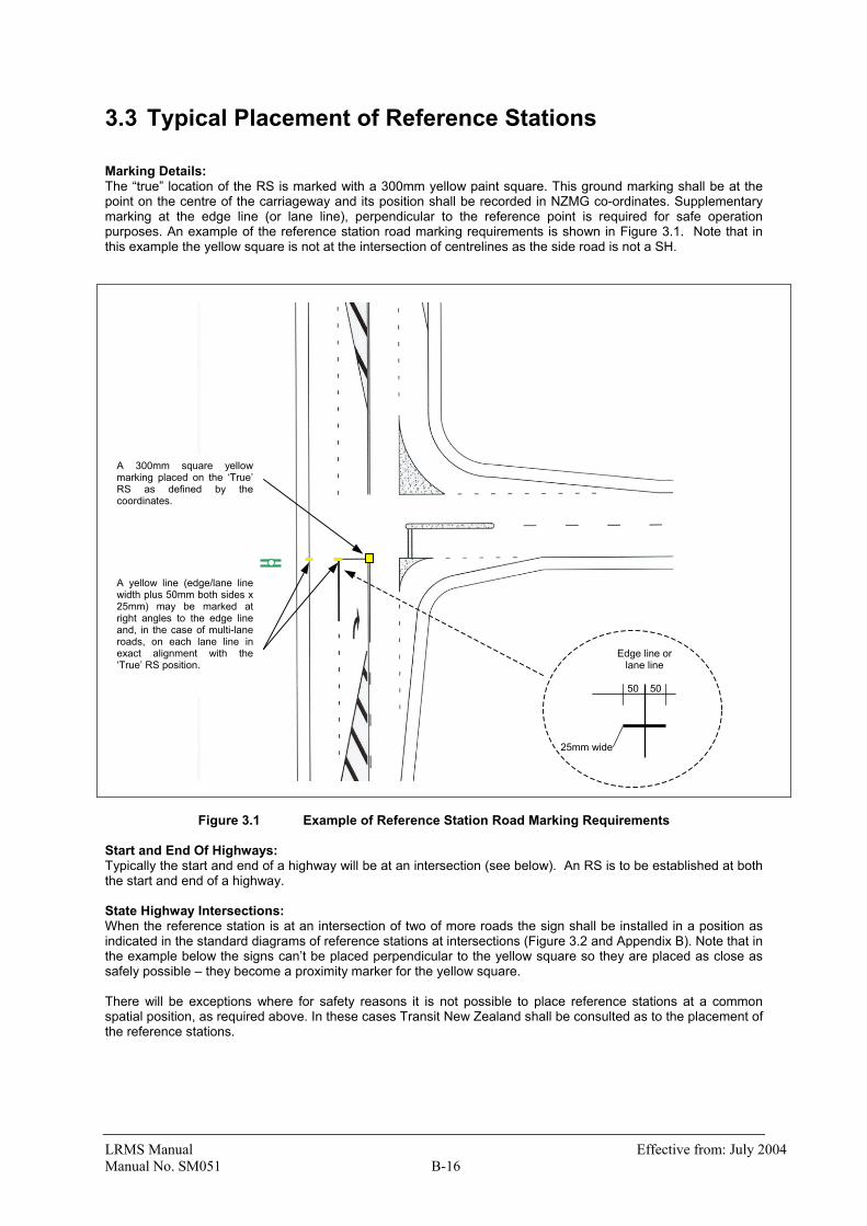
3.3 Typical Placement of Reference Stations Marking Details: The “true” location of the RS is marked with a 300mm yellow paint square. This ground marking shall be at the point on the centre of the carriageway and its position shall be recorded in NZMG co-ordinates. Supplementary marking at the edge line (or lane line), perpendicular to the reference point is required for safe operation purposes. An example of the reference station road marking requirements is shown in Figure 3.1. Note that in this example the yellow square is not at the intersection of centrelines as the side road is not a SH.
Figure 3.1 Example of Reference Station Road Marking Requirements Start and End Of Highways: Typically the start and end of a highway will be at an intersection (see below). An RS is to be established at both the start and end of a highway. State Highway Intersections: When the reference station is at an intersection of two of more roads the sign shall be installed in a position as indicated in the standard diagrams of reference stations at intersections (Figure 3.2 and Appendix B). Note that in the example below the signs can’t be placed perpendicular to the yellow square so they are placed as close as safely possible – they become a proximity marker for the yellow square. There will be exceptions where for safety reasons it is not possible to place reference stations at a common spatial position, as required above. In these cases Transit New Zealand shall be consulted as to the placement of the reference stations.
A 300mm square yellowmarking placed on the ‘True’RS as defined by thecoordinates. A yellow line (edge/lane linewidth plus 50mm both sides x25mm) may be marked atright angles to the edge lineand, in the case of multi-laneroads, on each lane line inexact alignment with the‘True’ RS position.
Edge line or lane line
50 50 25mm wide
LRMS Manual Effective from: July 2004 Manual No. SM051 B-17
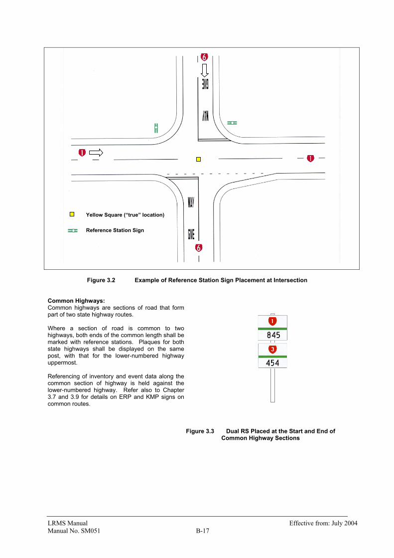
Figure 3.2 Example of Reference Station Sign Placement at Intersection Common Highways: Common highways are sections of road that form part of two state highway routes. Where a section of road is common to two highways, both ends of the common length shall be marked with reference stations. Plaques for both state highways shall be displayed on the same post, with that for the lower-numbered highway uppermost. Referencing of inventory and event data along the common section of highway is held against the lower-numbered highway. Refer also to Chapter 3.7 and 3.9 for details on ERP and KMP signs on common routes.
Figure 3.3 Dual RS Placed at the Start and End of Common Highway Sections
Yellow Square (“true” location) Reference Station Sign
LRMS Manual Effective from: July 2004 Manual No. SM051 B-18
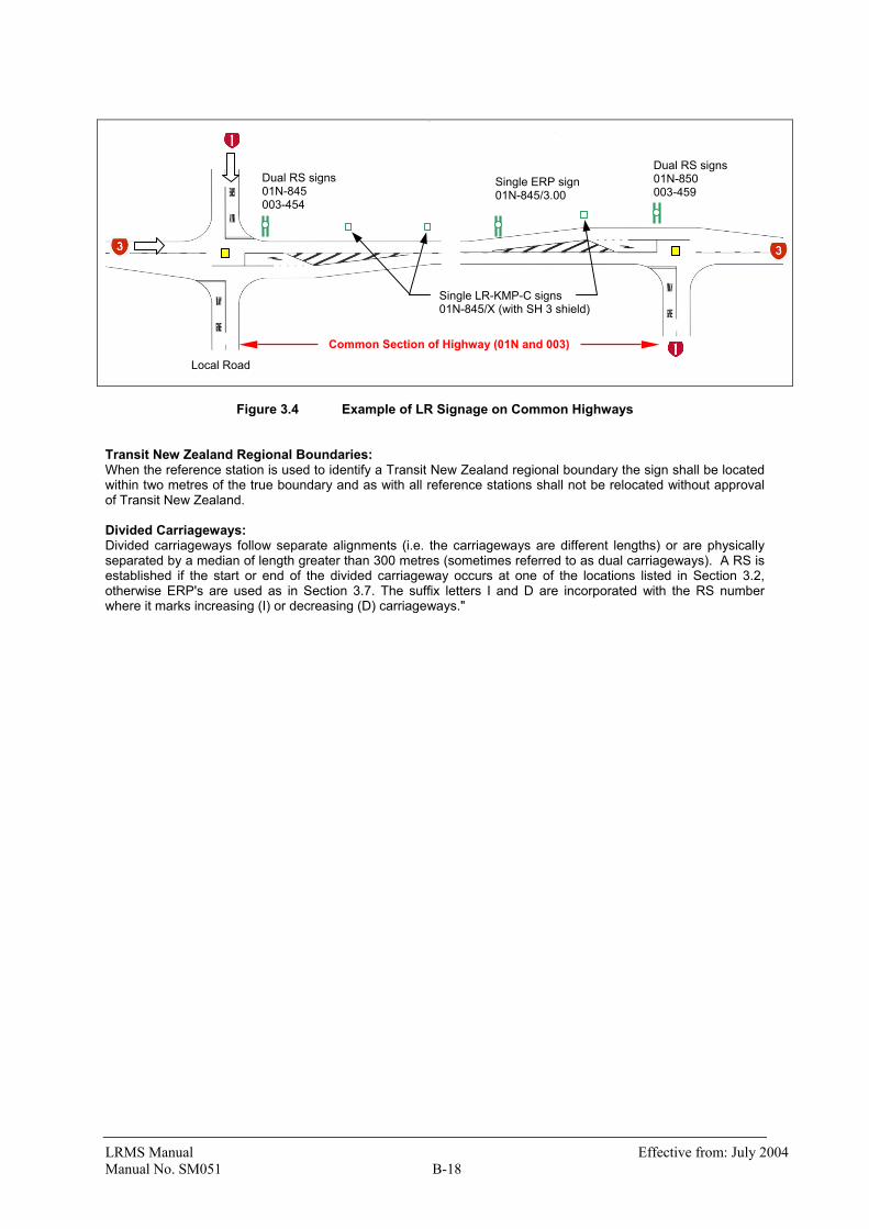
Figure 3.4 Example of LR Signage on Common Highways Transit New Zealand Regional Boundaries: When the reference station is used to identify a Transit New Zealand regional boundary the sign shall be located within two metres of the true boundary and as with all reference stations shall not be relocated without approval of Transit New Zealand. Divided Carriageways: Divided carriageways follow separate alignments (i.e. the carriageways are different lengths) or are physically separated by a median of length greater than 300 metres (sometimes referred to as dual carriageways). A RS is established if the start or end of the divided carriageway occurs at one of the locations listed in Section 3.2, otherwise ERP's are used as in Section 3.7. The suffix letters I and D are incorporated with the RS number where it marks increasing (I) or decreasing (D) carriageways."
Common Section of Highway (01N and 003)
Dual RS signs 01N-845 003-454
Dual RS signs 01N-850 003-459
Single ERP sign 01N-845/3.00
Single LR-KMP-C signs 01N-845/X (with SH 3 shield)
Local Road

LRMS Manual Effective from: July 2004 Manual No. SM051 B-19
Large Roundabout: The suffix letter “W” is incorporated with the RS number where it marks a large roundabout (refer Section 2.4). The following rules apply: The roundabout is given a unique number (as per assignment of RS numbers) The yellow square is to be placed beside the centre island on the increasing side of the roundabout (Figure
3.5). The RSW sign is to be placed within the centre island, perpendicular to the traffic lane. ERP’s are to be placed at the entry and exit from the roundabout.
Figure 3.5 shows an example of a roundabout on a divided highway. Further “actual” examples are included in Appendix D.
Figure 3.5 Establishing a Reference Station on a Large Roundabout (divided highway)
Yellow Paint Square (“true” location) Roundabout RS Sign Established Route Position
Increasing
Local Road
LRMS Manual Effective from: July 2004 Manual No. SM051 B-20
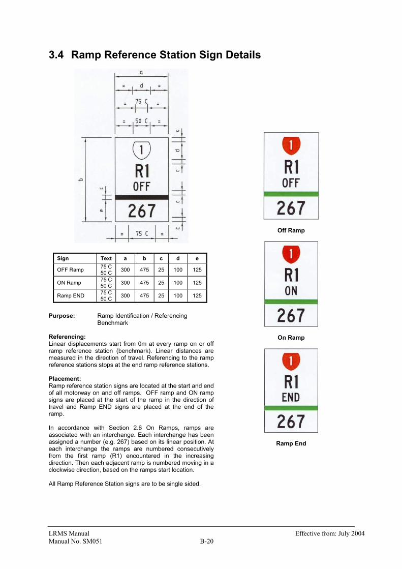
3.4 Ramp Reference Station Sign Details
Sign Text a b c d e OFF Ramp 75 C
50 C 300 475 25 100 125 ON Ramp 75 C
50 C 300 475 25 100 125 Ramp END 75 C
50 C 300 475 25 100 125
Purpose: Ramp Identification / Referencing Benchmark Referencing: Linear displacements start from 0m at every ramp on or off ramp reference station (benchmark). Linear distances are measured in the direction of travel. Referencing to the ramp reference stations stops at the end ramp reference stations. Placement: Ramp reference station signs are located at the start and end of all motorway on and off ramps. OFF ramp and ON ramp signs are placed at the start of the ramp in the direction of travel and Ramp END signs are placed at the end of the ramp. In accordance with Section 2.6 On Ramps, ramps are associated with an interchange. Each interchange has been assigned a number (e.g. 267) based on its linear position. At each interchange the ramps are numbered consecutively from the first ramp (R1) encountered in the increasing direction. Then each adjacent ramp is numbered moving in a clockwise direction, based on the ramps start location. All Ramp Reference Station signs are to be single sided.
Off Ramp
On Ramp
Ramp End

LRMS Manual Effective from: July 2004 Manual No. SM051 B-21
3.5 Typical Placement of Ramp Reference Station Marking: The “true” location of the ramp start is marked with a 300mm yellow paint square near or on the ramp kerb, where the lane becomes full lane width (3.5 m) and shown below Figure 3.6. The RS-R-ON or RS-R-OFF sign is placed on the verge perpendicular to the traffic lane.
Figure 3.6 Example of Ramp Reference Station Placement A Ramp END sign marks the ramp end. For on-ramps the end of the ramp is where the lane narrows to a width of less than 3.5m – generally indicated by the line markings. The yellow square indicates the authoritative position or alternatively the ramp length is measured from the sign. In the case of a lane gain, the sign placement becomes the definitive extent of the ramp.
Figure 3.7 Example of Ramp End Signage Changes to Ramp Lengths: Note that small changes to line markings should not necessitate the relocation of the Ramp RS. As long as the yellow square remains (accompanied by the sign and GPS co-ordinates), measurements can still be made relative to the ramp RS. However, if a significant extension of a ramp (>10m) occurs the RS should be relocated to allow data to be recorded/referenced against the new section of ramp. Ramps joining two state highways: For such cases refer to the State Highway Database Operation Manual SM050.
Ramp END
Ramp END
OFF Ramp
OFF Ramp

LRMS Manual Effective from: July 2004 Manual No. SM051 B-22
3.6 Established Route Position Sign Details
Sign Text a b c d ERP 75 C
50 C 540 250 25 100 ERP-D 75 C
50 C 640 250 25 100 ERP-I 75 C
50 C 640 250 25 100
Purpose: Intermediate Reference Post Referencing: Linear displacements from the RS are as
marked on the sign (e.g. 3.00km from RS 262)
Location: At intermediary positions between
reference stations, at divided carriageways and at roundabouts See section 3.7 for more detail
Placement: Established route positions are located at: • Divided carriageways • Exact 3km Intervals where possible1 and • Entry and exit of large roundabouts. Placed to a linear accuracy of ± 0.1% using the procedure given in Section Error! Reference source not found. Error! Reference source not found.. Note:
1. ERP’s can be placed between kilometre points (e.g. 2.62km) but where possible placement at exact kilometres reduces the number of kilometre markers required and simplifies setting trip meters.
2. As at July 2004 most ERP’s are not placed at exact kilometres. It is Transit’s intention to upgrade these on a replacement basis.
ERP
ERP-D Decreasing
ERP-I Increasing
LRMS Manual Effective from: July 2004 Manual No. SM051 B-23
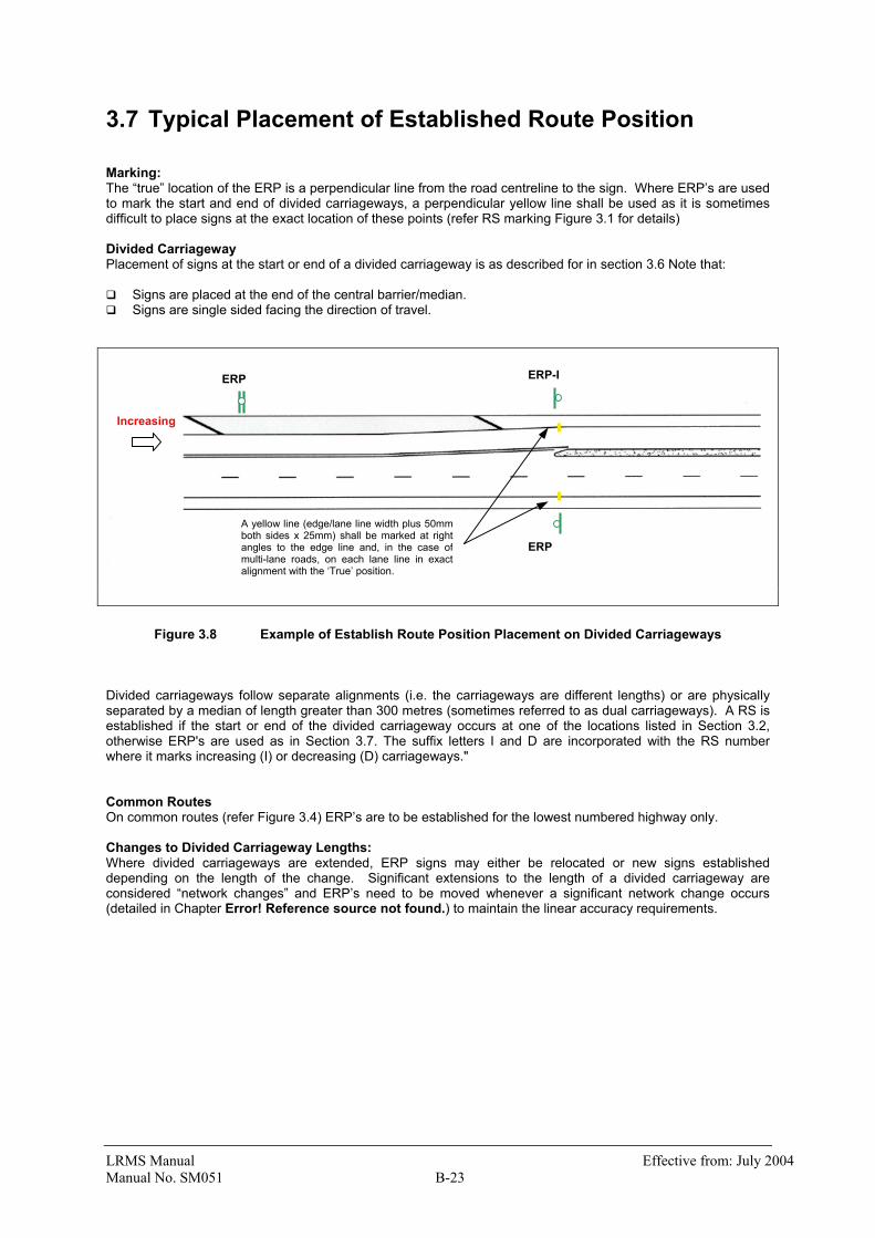
3.7 Typical Placement of Established Route Position Marking: The “true” location of the ERP is a perpendicular line from the road centreline to the sign. Where ERP’s are used to mark the start and end of divided carriageways, a perpendicular yellow line shall be used as it is sometimes difficult to place signs at the exact location of these points (refer RS marking Figure 3.1 for details) Divided Carriageway Placement of signs at the start or end of a divided carriageway is as described for in section 3.6 Note that: Signs are placed at the end of the central barrier/median. Signs are single sided facing the direction of travel.
Figure 3.8 Example of Establish Route Position Placement on Divided Carriageways Divided carriageways follow separate alignments (i.e. the carriageways are different lengths) or are physically separated by a median of length greater than 300 metres (sometimes referred to as dual carriageways). A RS is established if the start or end of the divided carriageway occurs at one of the locations listed in Section 3.2, otherwise ERP's are used as in Section 3.7. The suffix letters I and D are incorporated with the RS number where it marks increasing (I) or decreasing (D) carriageways." Common Routes On common routes (refer Figure 3.4) ERP’s are to be established for the lowest numbered highway only. Changes to Divided Carriageway Lengths: Where divided carriageways are extended, ERP signs may either be relocated or new signs established depending on the length of the change. Significant extensions to the length of a divided carriageway are considered “network changes” and ERP’s need to be moved whenever a significant network change occurs (detailed in Chapter Error! Reference source not found.) to maintain the linear accuracy requirements.
ERP
Increasing
ERP-I
ERP
A yellow line (edge/lane line width plus 50mmboth sides x 25mm) shall be marked at rightangles to the edge line and, in the case ofmulti-lane roads, on each lane line in exactalignment with the ‘True’ position.

LRMS Manual Effective from: July 2004 Manual No. SM051 B-24
3.8 Kilometre Marker Post Sign Details
Sign Text a b c d e f g
KMP 75 C 50 C 100 900 25 430 15
KMP-D 75 C 50 C 100 900 25 430 15 80 125
KMP-I 75 C 50 C 100 900 25 430 15 80 125
KMP-C 75 C 50 C 100 900 25 430 15 75 125
Purpose: Approximate location guide sign Referencing: The approximate displacement from the RS Placement: Kilometre marker posts are generally located at 1km intervals on the true left side of the carriageway (i.e. the left side of the roadway when moving in the increasing direction). The exception is for divided carriageways when the KMP-D signs are placed on the left side while moving in the decreasing direction. Placed to a linear accuracy of ± 100m. This is a minimum standard and regions may decide to place signs to a great level of accuracy. The markers shall generally be separate posts, however in urban areas the marker may be fastened to an existing service pole. However, KMP are not required for urban areas and their placement in urban areas is at the discretion of the region.
KMP KMP-C
KMP-D KMP-I Decreasing Increasing

LRMS Manual Effective from: July 2004 Manual No. SM051 B-25
3.9 Typical Placement of Kilometre Marker Post Divided Carriageway: Kilometre marker posts are placed on both sides of the divided carriageway. If the increasing and decreasing directions are different lengths, these will not be located opposite each other. The shield and lettering are only marked on one side of the KMP on divided carriageways.
Figure 3.9 Example of Kilometre Marker Post Placement on Divided Carriageways Common Routes: On common routes, the KMPs are placed according to the lower numbered highway but include the shield (75mm) of the higher numbered highway. Refer KMP-C above and Figure 3.4
RS or ERP Sign Kilometre Marker Post
Double Sided Single Sided

LRMS Manual Effective from: July 2004 Manual No. SM051 B-26
This page intentionally blank