Embed Size (px)
Citation preview
CRAIG O. SAVAGEBILL MORANRaytheon Missile SystemsGuidance, Navigation & Control1151 E. Hermans Rd.Tuscon, AZ 85706E-mail: ([email protected])
REFERENCES
[1] Kalandros, M., and Pao, L. Y.Covariance control for multisensor systems.IEEE Transactions on Aerospace and Electronic Systems,38, 4 (Oct. 2000), 1138—1157.
[2] Bar-Shalom, Y., and Xiao-Rong, L.Estimation and Tracking: Principles, Techniques, andSoftware.Norwood, MA: Artech House, 1993.
[3] Bar-Shalom, Y., and Xiao-Rong, L.Multitarget-Multisensor Tracking: Principles andTechniques (a.k.a. “The Yellow Book”).Storrs, CT: YBS Publishing, 1995
[4] Kershaw, D., and Evans, R.Adaptive waveform selection for tracking in clutter.Proceedings of the American Control Conference,Baltimore, MD, June, 1994.
[5] Kershaw, D., and Evans, R.Optimal waveform selection for tracking systems.IEEE Transactions on Information Theory, 40, 5 (Sept.1994), 1536—1550.
[6] Kershaw, D., and Evans, R.Waveform selective probabilistic data association.IEEE Transactions on Aerospace and Electronic Systems,33 (Oct. 1997), 1180—1188.
[7] La Scala, B., Moran, B., and Evans, R.Optimal adaptive waveform selection for target detection.Radar 2003: International Conference on Radar. Adelaide,Australia, Sept. 2003.
[8] Niu, R., Willett, P., and Bar-Shalom, Y.Tracking considerations in selection of radar waveformfor range and range-rate measurements.IEEE Transactions on Aerospace and Electronic Systems,38, 2 (Apr. 2002), 467—487.
[9] Niu, R., Willett, P., and Bar-Shalom, Y.Further analysis of waveform effects on trackingperformance.Aerospace Conference Proceedings, vol. 3, 2000, 417—431.
[10] Rago, C., Willett, P., and Bar-Shalom, Y.Detection-tracking performance with combinedwaveforms.IEEE Transactions on Aerospace and Electronic Systems,34, 2 (1998), 612—624.
[11] Fielding, P. J., and Kinghorn, A. M.Waveform optimisation for efficient resource allocation inairborne AESA radar systems.In Multifunction Radar and Sonar Sensor ManagementTechniques. IEE, Nov. 26, 2001.
[12] van Trees, H.Detection, Estimation, and Modulation Theory, Part III.New York: Wiley, 1968.
[13] Borden, B.The fractional Fourier transform and ISAR imaging.Inverse Problems, 16, 2 (Apr. 2000), Available online athttp://www.iop.org, as of Sept. 1, 2004.
[14] Ozaktas, H. M., and Kutay, M. A.Effect of fractional Fourier transformation ontime-frequency distributions belonging to the Cohen class.IEEE Transactions on Signal Processing Letters, 40, 1(1996), 40—41.
[15] Mustard, D.Uncertainty principles invariant under the fractionalFourier transform.Journal of the Australian Mathematic Society, 33, Series B(1991), 180—191.
[16] The Fractional Fourier Transform.http://www.ee.bilkent.edu.tr/»haldun/wileybook.html.
[17] Bargmann, V.On a Hilbert space of analytic functions and an associatedintegral transform, Part I.Communications of Pure and Applied Mathematics, 14(1961), 187—214.
Location and Imaging of Moving Targets usingNonuniform Linear Antenna Array SAR
By using a linear antenna array, velocity synthetic aperture
radar (VSAR) can detect, focus, and locate slowly moving targets
well. However, it may mis-locate fast moving targets in the
azimuth (cross-range) direction. In this correspondence, we
propose a synthetic aperture radar (SAR) with a nonuniform
linear antenna array and give a design of the antenna
arrangement. It is shown that our proposed nonuniform linear
antenna array SAR (NULA-SAR) can locate both slowly and fast
moving targets correctly. An integrated NULA-SAR algorithm for
moving target imaging is also presented, and it is verified by some
simulations.
I. INTRODUCTION
Synthetic aperture radar (SAR) location andimaging of moving targets has attracted muchattention in recent decades. It is known that thedifficulty of moving target location and imaging is theestimation of moving target position and velocities.In the single-channel SAR systems, classical
methods for moving target imaging are mostly basedon the analysis of the azimuth phase history [1—3]. Aspointed out in [2], when the targets move fast such
Manuscript received October 25, 2005; revised August 22 andDecember 15, 2006; released for publication July 26, 2007.
IEEE Log No. T-AES/43/3/908444.
Refereeing of this contribution was handled by P. Lombardini.
This work was partially supported by the China NationalScience Foundation (CSNF) under Grant 60502012, partiallysupported by China Ministry Research Foundation under Grant51407030203JW0141 and partially supported by the ChinaAerospace Supporting Foundation under Grant J04-2005047. Xia’swork was partially supported by the Air Force Office of ScientificResearch (AFOSR) under Grant FA9550-05-1-0161.
0018-9251/07/$25.00 c° 2007 IEEE
1214 IEEE TRANSACTIONS ON AEROSPACE AND ELECTRONIC SYSTEMS VOL. 43, NO. 3 JULY 2007

that their Doppler centroids exceed the pulse repetitionfrequency (PRF), the radial velocities and, therefore,the azimuth positions of the targets cannot be uniquelyestimated. In higher signal-clutter-ratio (SCR) case,some algorithms not subject to the limitation ofthe PRF have been proposed in [4], [5], and [6],where the velocity estimations are implemented bytracking the positions of targets in the sequence ofmulti-look SAR images [4], or by computing the skewof the two-dimensional spectral signature [5], or byanalyzing the different phase histories under differentplatform speeds [6], respectively.In order to suppress the clutter and better detect
and image moving targets, some methods based onmulti-receiver SAR system have been presented, e.g.,space-time-frequency processing [7], multi-channelSAR [8], uniform linear antenna array SAR (calledalso velocity SAR or VSAR) [9] etc. As reportedin [9], in VSAR system, stationary clutter can berejected, and slowly moving targets (such as walkingpeople) can be properly detected and imaged viadigital Fourier transform (DFT) operation on themultiple complex images formed by a uniformlinear antenna array, but fast moving targets (suchas moving vehicles) may still be mis-located in theazimuth direction due to the 2¼ modulo folding of theDFT. To overcome the azimuth location ambiguity,multi-frequency VSAR and dual-speed VSAR havebeen proposed in [10] and [11], respectively, where ahigher complexity of the transmitter and receivers (formulti-frequency VSAR) or a higher maneuverabilityof the platform (for dual-speed VSAR) is required.We are also interested here in resolving the
azimuth location ambiguity. We equip a conventionalSAR with a nonuniform linear antenna array anddesign-specific arrangement of the elements. Thisnew system is named nonuniform linear antennaarray SAR (NULA-SAR). In the NULA-SARsystem, a series of complex images are formed by thenonuniform linear antenna array, and two (or multiple)subsets are extracted from the image series. In eachsubset, the moving targets may be separated fromthe stationary clutter, and the different informationbetween the two (or multiple) subsets and the Chineseremainder theorem (CRT) [12] are used to resolve theazimuth location ambiguity. Therefore, NULA-SARhas the ability not only to suppress clutter but also tolocate both slowly and fast moving targets correctly.In comparison with the multi-frequency VSAR [10]and the dual-speed VSAR [11], NULA-SAR doesnot require higher complexity of the transmitter andthe receivers, or the higher maneuverability of theplatform, respectively.This paper is organized as follows. In Section II
we introduce the NULA-VSAR model, formulate thesolution of azimuth location ambiguity, and analyzethe location accuracy. In Section III an integratedNULA-SAR algorithm for moving target imaging
Fig. 1. NULA-SAR geometry.
is proposed. In Section IV some simulation resultsof ground moving targets are given to prove theeffectiveness of NULA-SAR algorithm.
II. MOVING TARGETS LOCATION USING NULA-SAR
In this section, the NULA-SAR model isintroduced first. The azimuth location ambiguity ofVSAR is then addressed. The location ambiguitysolution using the NULA-SAR is finally presented,and the location accuracy is also studied.
A. NULA-SAR Model
NULA-SAR geometry is illustrated in Fig. 1.X-axis is the azimuth direction and Y-axis is the rangedirection. The radar platform flies along azimuthdirection with altitude H and velocity v. Whent= 0, a point-like moving target P with constantazimuth-direction speed vx and range-direction speedvy is assumed located at (x0,y0,0). At the same time,the transmitter and the first receiver antenna areassumed colocated at (0,0,H), and the other 2M ¡ 2receiver antennas are arranged at the followingcoordinates: (d1,0,H), (2d1,0,H), : : : , ((M ¡ 1)d1,0,H)and (d2,0,H), (2d2,0,H), : : : , ((M ¡ 1)d2,0,H), asshown in Fig. 1(b) and (c), respectively. It is nothard to see that the set Q of all antennas is the unionof two subsets Q1 and Q2, i.e., Q =Q1 [Q2, whereQ1 and Q2 are located at instantaneous azimuthcoordinate sets fvt+md1;m= 0,1,2, : : : ,M ¡ 1gand fvt+md2;m= 0,1,2, : : : ,M ¡ 1g, respectively.In addition, d1 and d2 are two distinct positive realnumbers and not integer multiple of each other.
B. Azimuth Location Ambiguity of VSAR
Note that Q1 is a uniform array composed of Melements with spacing d1. Firstly, let us review theVSAR location processing in Q1.After the range compression and the azimuth
focusing, the image of P formed by the mth antenna
CORRESPONDENCE 1215

of Q1 may be represented as [9, 10]
S1,m(n, l) = expμ¡j2¼½xn0md1
R0¸
¶¢ ±(n¡ n0¡¢shift) ¢ ±(l¡ l0) (1)
where the amplitude and the constant phase term isignored for convenience; R0 is the distance from the
transmitter to P at t= 0, i.e., R0 =qx20 + y
20 +H
2; ¸ isthe carrier wavelength; l0 is certain range cell whereP locates after the range compression; n0 and ¢shiftare quantization results of x0 and target’s azimuthmigration by the azimuth resolution ½x, respectively.As pointed out in [9], [10], ¢shift may be representedas
¢shift = (x0vx+ y0vy)=(v½x): (2)
The problem of interest herein is to locate P atits true azimuth position n0. To do so, ¢shift mustbe estimated accurately and subtracted from thedetected position (n0 +¢shift). Multiplying the phasefactor exp[j2¼(n0 +¢shift)½xmd=(R0¸)] to with theknowledge of the detected position (n0 +¢shift), (1)becomes
S1(m) = expμj2¼
½x¢shiftmd1R0¸
¶¢ ±(n¡ n0¡¢shift)
(3)
for m= 0,1, : : : ,M ¡ 1. Defining the normalizedfrequency
f1 = ½x¢shiftd1=(R0¸) (4)
(3) can be rewritten as
S1(m) = exp(j2¼f1m) ¢ ±(n¡n0¡¢shift) (5)
which shows clearly that f1 and, therefore, ¢shift canbe estimated via DFT of S1(m) in terms of m. In theM-point DFT results (defined as V-images in [9]and detailed definition is given in the Appendix),we have f 01 = mod(f1,1) that is the residue of f1due to the 2¼ folding operation of the DFT. If Pmoves slowly such that 0· f 01 = f1 < 1, f1 and,therefore, ¢shift can be estimated in the V-images,and thus there is no location ambiguity in this case.Otherwise, if P moves fast such that f1 = f
01 +K1 for
an unknown integer K1, the estimation of ¢shift willnot be determined uniquely by using a single residuef 01 i.e., the location ambiguity will occur. This is thereason why in a VSAR system walking people can belocated, but moving vehicles may not be positionedcorrectly [9]. To overcome the location ambiguity,a multi-frequency VSAR system has been proposedin [10], where multiple carrier wavelengths ¸ areused such that multiple DFTs can be applied to thesedata from multiple carrier wavelengths, and multipleresidues of f1 can be obtained in (4), and then ¢shiftcan be determined uniquely by CRT. The dual-speed
VSAR [11] is also based on the similar idea. From(4) we note that multiple antenna-spacings d1 alsocan produce multiple residues of f1. This is the ideaof the following NULA-SAR accurate location formoving targets by using multiple groups of antennaswith distinct spacings.
C. NULA-SAR Location Principle
Now we perform DFT not only along antennasin Q1 but also along antennas in Q2. Like the aboveanalysis, from (4) and (5), we directly have
f2 = ½x¢shiftd2=(R0¸) = f02 +K2 (6)
S2(m) = exp(j2¼f2m) ¢ ±(n¡ n0¡¢shift): (7)
where S2(m) is the focused image of P obtained at themth antenna of Q2, f
02 = mod(f2,1), K2 is an unknown
integer. Let Li = R0¸=(½xdi), (4) and (6) show
¢shift = (f0i +Ki)Li (8)
which means
f 0i Li = mod(¢shift,Li) (9)
for i= 1,2. Therefore, the moving target locationproblem is equivalent to determine the value of ¢shiftfrom its two residues f 0i Li, for i= 1,2. By usingthe CRT, ¢shift can be uniquely determined if it isless than the least common multiple of L1 and L2(expressed LCM(L1,L2) for short). Once ¢shift isknown, the moving target P can be located correctlyby subtracted ¢shift from the detected position (n0 +¢shift), i.e., the azimuth location ambiguity can beresolved.If only one subset Q1 or Q2 is employed,
LCM(L1,L2) is reduced to L1 or L2 accordingly.Because d1 and d2 are assumed not integer multiplesof each other, L1 and L2 are not integer multiplesof each other accordingly. Hence LCM(L1,L2)> Lifor i= 1,2. Therefore, the maximal determinablevalue of ¢shift can be increased over the one whenonly one subset Qi is employed, which correspondsto that the maximal determinable velocity (or blindspeed in radar jargon) of the moving target can beincreased (see (2)). In (2), the term x0vx can generallybe neglected, because y0 ¼ R0 and x0 is usually muchsmaller than y0. Thus the determinable upper limit of¢shift can be represented as
¢shift,max ¼ R0vy,max=(v½x) = LCM(L1,L2) (10)
and then the blind (maximal) speed of NULA-SAR is
jvy,maxj=12¢ v½xLCM(L1,L2)
R0(11)
where 1/2 is multiplied because there are two differentpossible directions of vy, toward and away from theradar, respectively.
1216 IEEE TRANSACTIONS ON AEROSPACE AND ELECTRONIC SYSTEMS VOL. 43, NO. 3 JULY 2007
In practice, the size of an antenna array is limitedby the allowed space in a radar platform, and thenumber of antennas is limited by allowed complexityof the system. Hence, it is worth comparing thelocation performances between NULA-SAR anduniform linear antenna array SAR, i.e., VSAR, withthe same size of antenna array and the same numberof antennas. Without loss of generality, we assumed2 < d1. According to the model of NULA-SAR,the array size is Z = (M ¡ 1)d1, that is assumedpredefined array size of the radar platform. Theantenna number of NULA-SAR N · 2M ¡ 1, wherethe equality holds if and only if Q1 \Q2 =© (©means the empty set). If a VSAR with N elementsis set in Z, its inter-element spacing is
d0 =Z
N ¡ 1 ¸(M ¡1)d12M ¡ 2 = d1=2: (12)
From (4), (12), and the definition of L1, one cansee that the maximal determinable value of ¢shiftusing this VSAR is 2L1. As mentioned above,LCM(L1,L2)> L1, i.e., LCM(L1,L2)¸ 2L1. Thus forthe same array size and the same number of antennas,NULA-SAR can get larger determinable range of¢shift than VSAR. In other words, the blind speedof NULA-SAR is above the one of VSAR withoutincreasing the antenna spacing and the complexity ofthe system.
D. Study on Location Accuracy
What was studied above provides the basic idea of¢shift estimation by using the CRT in the V-images,which is based on two assumptions: 1) Li are integers;2) the estimated residues f 0i in the V-images areaccurate, for i= 1,2. However, in practice theseassumptions may not hold. In particular, smallestimation error of f 0i will cause large estimation errorof ¢shift. Now we analyze the effect of the estimationerror of f 0i on the location accuracy.The zero-padded NDFT-point DFT on (5) and (7) in
terms of m gives
f 0i =NiNDFT
+ "i (13)
where Ni are certain integers with 0·Ni < NDFT andthey are directly obtained in the DFT results, "i arethe uncertain errors, and "i · 1=(2NDFT), for i= 1,2.Accordingly, (8) can be rewritten as
¢shift =NiNDFT
Li+KiLi+ "iLi (14)
where Li does not need to be integers, for i = 1,2.When NDFT > L1 +L2, the robust CRT [10] gives
¢̂shift =R0¸
2½x
2Xi=1
μKi+
NiNDFT
¶¢ 1di
(15)
where Ki are determined by
(K1,K2) = argmin0·K̄1<LCM(L1,L2)=L10·K̄2<LCM(L1,L2)=L2
¯̄̄̄K̄1L1 +
N1NDFT
L1¡ K̄2L2¡N2NDFT
L2
¯̄̄̄
for integer pair (K̄1,K̄2): (16)
The accuracy of the solution of ¢shift in (15) can beestimated as
j¢shift¡ ¢̂shiftj ·R0¸
4NDFT½x
2Xi=1
1di: (17)
This means that the location error can be reduced byincreasing NDFT. If the location error is limited withinan azimuth cell, i.e., let j¢shift,i¡ ¢̂shift,ij< 1, the NDFTneeds to satisfy
NDFT >R0¸
4½x
2Xi=1
1di: (18)
About the details of the robust CRT, we refer thereader to [10].
III. NULA-SAR ALGORITHM FOR MOVING TARGETIMAGING
Based on the moving target accurate locationstudied above, a NULA-SAR algorithm for movingtarget imaging is presented below. All the followingsteps, except Step 7, are common operations for Q1and Q2.
Step 1 Two-dimensional matching filter with theimpulse response function of the stationary scene isused to obtain the scene image.Step 2 Perform M-point DFT along the antenna
array direction to get the V-images.Step 3 Remove the 0th V-image, i.e., replace
the 0th V-image by 0, to reject the clutter. Thedetailed discussion about this step is in theAppendix.Step 4 Perform M-point inverse DFT along the
antenna array direction.Step 5 In the range cell where a moving target is
detected, estimate the chirp rate of the azimuth signalby applying the method proposed in [13], and thenfocus the target by compensating the correspondingquadratic phase term.Step 6 Carry out zero-padded NDFT-point DFT
along the antenna array direction to get the newV-images.Step 7 In new V-images, estimate ¢shift according
to (15), as described in previous section.Step 8 Take NDFT-point inverse DFT along the
antenna array direction.Step 9 Relocate the moving target in terms of the
estimated ¢shift.
CORRESPONDENCE 1217
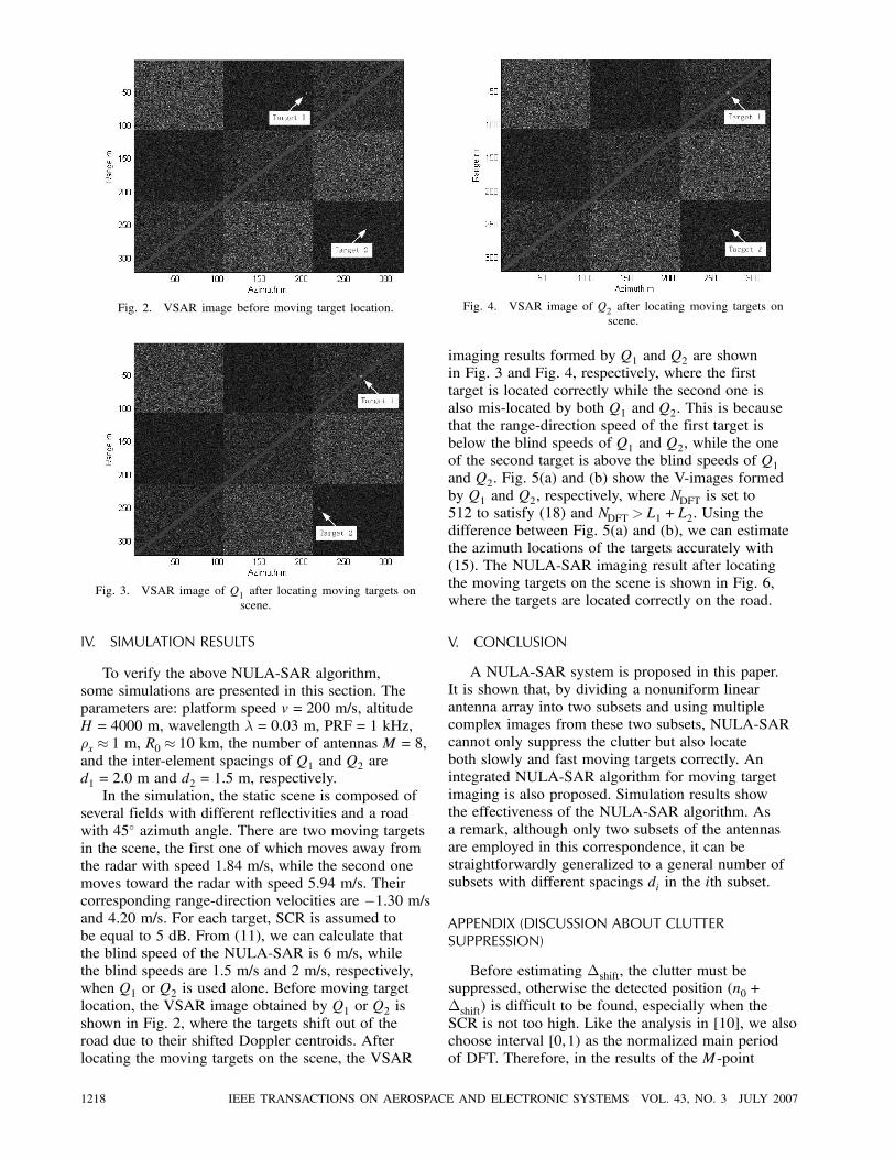
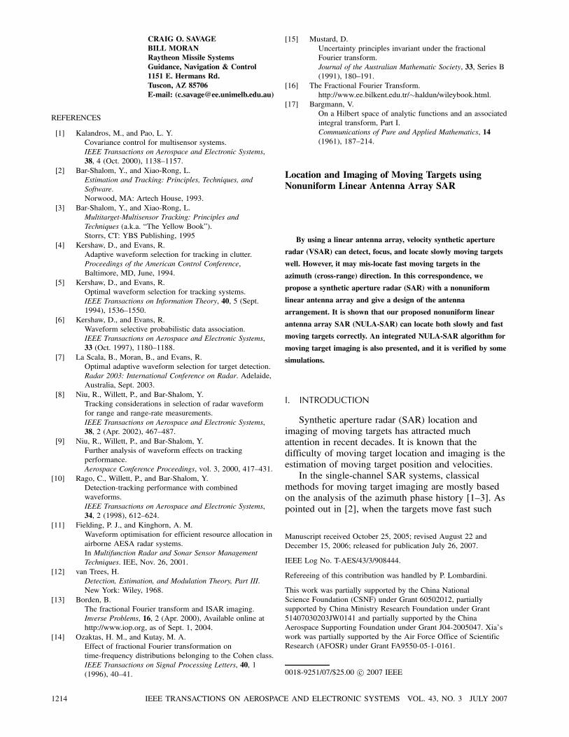
Fig. 2. VSAR image before moving target location.
Fig. 3. VSAR image of Q1 after locating moving targets onscene.
IV. SIMULATION RESULTS
To verify the above NULA-SAR algorithm,some simulations are presented in this section. Theparameters are: platform speed v = 200 m/s, altitudeH = 4000 m, wavelength ¸= 0:03 m, PRF = 1 kHz,½x ¼ 1 m, R0 ¼ 10 km, the number of antennas M = 8,and the inter-element spacings of Q1 and Q2 ared1 = 2:0 m and d2 = 1:5 m, respectively.In the simulation, the static scene is composed of
several fields with different reflectivities and a roadwith 45± azimuth angle. There are two moving targetsin the scene, the first one of which moves away fromthe radar with speed 1.84 m/s, while the second onemoves toward the radar with speed 5.94 m/s. Theircorresponding range-direction velocities are ¡1:30 m/sand 4.20 m/s. For each target, SCR is assumed tobe equal to 5 dB. From (11), we can calculate thatthe blind speed of the NULA-SAR is 6 m/s, whilethe blind speeds are 1.5 m/s and 2 m/s, respectively,when Q1 or Q2 is used alone. Before moving targetlocation, the VSAR image obtained by Q1 or Q2 isshown in Fig. 2, where the targets shift out of theroad due to their shifted Doppler centroids. Afterlocating the moving targets on the scene, the VSAR
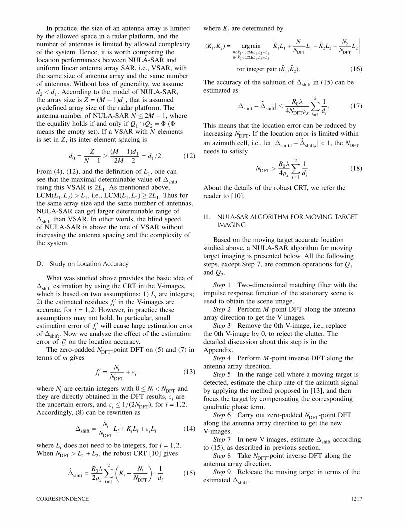
Fig. 4. VSAR image of Q2 after locating moving targets onscene.
imaging results formed by Q1 and Q2 are shownin Fig. 3 and Fig. 4, respectively, where the firsttarget is located correctly while the second one isalso mis-located by both Q1 and Q2. This is becausethat the range-direction speed of the first target isbelow the blind speeds of Q1 and Q2, while the oneof the second target is above the blind speeds of Q1and Q2. Fig. 5(a) and (b) show the V-images formedby Q1 and Q2, respectively, where NDFT is set to512 to satisfy (18) and NDFT > L1 +L2. Using thedifference between Fig. 5(a) and (b), we can estimatethe azimuth locations of the targets accurately with(15). The NULA-SAR imaging result after locatingthe moving targets on the scene is shown in Fig. 6,where the targets are located correctly on the road.
V. CONCLUSION
A NULA-SAR system is proposed in this paper.It is shown that, by dividing a nonuniform linearantenna array into two subsets and using multiplecomplex images from these two subsets, NULA-SARcannot only suppress the clutter but also locateboth slowly and fast moving targets correctly. Anintegrated NULA-SAR algorithm for moving targetimaging is also proposed. Simulation results showthe effectiveness of the NULA-SAR algorithm. Asa remark, although only two subsets of the antennasare employed in this correspondence, it can bestraightforwardly generalized to a general number ofsubsets with different spacings di in the ith subset.
APPENDIX (DISCUSSION ABOUT CLUTTERSUPPRESSION)
Before estimating ¢shift, the clutter must besuppressed, otherwise the detected position (n0 +¢shift) is difficult to be found, especially when theSCR is not too high. Like the analysis in [10], we alsochoose interval [0,1) as the normalized main periodof DFT. Therefore, in the results of the M-point
1218 IEEE TRANSACTIONS ON AEROSPACE AND ELECTRONIC SYSTEMS VOL. 43, NO. 3 JULY 2007

Fig. 5. V-images of moving targets. (a) V-images at Q1.(b) V-images at Q2.
Fig. 6. NULA-SAR image after locating moving targets onscene.
DFT along Q1 or Q2 at every pixel of the M SARimages, the ith channel corresponds to the normalizedfrequency i=M, for i= 0,1, : : : ,M ¡ 1. All of the ithchannels at all pixels after the M-point DFT composethe ith V-image. From (2), (4), and (6), one can seethat, in the results of the DFT along Q1 or Q2, f1 =f2 = 0 for stationary targets, i.e., the stationary targetsstand in the 0th V-image formed at Q1 or Q2. Thusthe stationary clutter can be suppressed by removingthe 0th V-image, i.e., replacing the 0th V-image by 0.Occasionally, the moving target may also stand in the0th V-image due to the 2¼ folding operation of DFT,and it may be removed in company with the clutter.But it is impossible that the moving target stands inboth 0th V-images formed at Q1 and Q2. (Proof: ifthe moving target stands in both 0th V-images formedby Q1 and Q2, we have ¢shift =K1L1 =K2L2. Thismeans ¢shift =K ¢LCM(L1,L2) for a certain integerK. Because of the restriction of ¢shift < LCM(L1,L2),we have K = 0 and ¢shift = 0. Moreover, x0¿ y0 andthe values of vx and vy are comparable, thus ¢shift = 0
is hold if and only if vx = vy = 0 (see (2)). This isinconsistent with the fact that the target is moving.)Therefore, ¢shift also can be determined by the CRT,where one of its two residues is equal to zero. Thisdiscussion about the clutter suppression is similarto the one in multi-frequency VSAR [10]. Also, itis necessary to explain the difference of the DFTbetween Step 2 and Step 6. In Step 2, M-point DFT isenough to separate the moving targets from the clutter,because the frequency resolution of the DFT is 1=Mthat is limited by the Rayleigh bound. In Step 6, thepurpose of using zero-padded NDFT-point DFT is toimprove the frequency estimation accuracy.
GANG LIJIA XU1
YING-NING PENGDept. of Electronic EngineeringTsinghua UniversityBejing 100084China
XIANG-GEN XIADept. of Electrical and Computer EngineeringUniversity of DelawareNewark, DE 19716E-mail: ([email protected])
1Also with Radar Academy of Airforce Wuhan, 430010 China.
REFERENCES
[1] Werness, S. A. S., Carrara, W. G., Joyce, L. S., andFranczak, D. B.Moving target imaging algorithm for SAR data.IEEE Transactions on Aerospace and Electronic Systems,26, 1 (1990), 57—67.
[2] Barbarossa, S.Detection and imaging of moving objects with syntheticaperture radar.IEE Proceedings, Pt. F, 139, 1 (1992), 79—88.
[3] Perry, R. P., DiPietro, R. C., and Fante, R. L.SAR imaging of moving targets.IEEE Transactions on Aerospace and Electronic Systems,35, 1 (1999), 188—200.
[4] Kirscht, M.Detection and imaging of arbitrarily moving targets withsingle-channel SAR.IEE Proceedings–Radar Sonar & Navigation, 150, 1(2003), 7—11, 2003.
[5] Marques, P., and Dias, J.Velocity estimation of fast moving targets using a singleSAR sensor.IEEE Transactions on Aerospace and Electronic Systems,41, 1 (2005), 75—89.
[6] Wang, G., Xia, X.-G., and Chen, V. C.Dual-speed SAR imaging of moving targets.IEEE Transactions on Aerospace and Electronic Systems,42, 1 (2006), 368—379.
[7] Barbarossa, S., and Farina, A.Space-time-frequency processing of synthetic apertureradar signals.IEEE Transactions on Aerospace and Electronic Systems,30, 2 (1994), 341—358.
CORRESPONDENCE 1219

[8] Ender, J.Detection and estimation of moving target signals bymulti-channel SAR.In Proceedings of EUSAR’96 Conference, 1996, 411—417.
[9] Friedlander, B., and Porat, B.VSAR: A high resolution radar system for detection ofmoving targets.IEE Proceedings–Radar, Sonar & Navigation, 144, 4(1997), 205—218.
[10] Wang, G., Xia, X.-G., Chen, V. C., and Fiedler, R. L.Detection, location, and imaging of fast moving targetsusing multifrequency antenna array SAR.IEEE Transactions on Aerospace and Electronic Systems,40, 1 (2004), 345—355.
[11] Li, G., Xu, J., Peng, Y.-N., and Xia, X.-G.Moving target location and imaging using dual-speedvelocity SAR.IET Radar Sonar & Navigation, 1, 2 (2007), 158—163.
[12] McClellan, J. H., and Rader, C. M.Number Theory in Digital Signal Processing.Englewood Cliffs, NJ: Prentice-Hall, 1979.
[13] Wood, J., and Barry, D.Linear signal synthesis using the Radon-Wignertransform.IEEE Transaction on Signal Processing, 42, 8 (1994),2105—2111.
Weather Radar Equation Correction for FrequencyAgile and Phased Array Radars
This paper presents the derivation of a correction to the
Probert-Jones weather radar equation for use with advanced
frequency agile, phased array radars. It is shown that two
additional terms are required to account for frequency hopping
and electronic beam pointing. The corrected weather radar
equation provides a basis for accurate and efficient computation
of a reflectivity estimate from the weather signal data samples.
Lastly, an understanding of calibration requirements for these
advanced weather radars is shown to follow naturally from the
theoretical framework.
I. INTRODUCTION
The classical weather radar equation wasintroduced by Probert-Jones in 1962 [1] and has
Manuscript received May 1, 2006; revised November 24, 2006 andJuly 18, 2007; released for publication July 18, 2007.
IEEE Log No. T-AES/43/3/908445.
Refereeing of this contribution was handled by E. S. Chornoboy.
This work was supported in part by the Office of Naval Researchthrough a Cooperative Research and Development Agreement,NCRADA-NPS-03-0052, between Naval Postgraduate School,Monterey, CA and ProSensing, Inc., Amherst, MA.
0018-9251/07/$25.00 c° 2007 IEEE
since been universally used to implement reflectivityalgorithms. These algorithms are used to computereflectivity estimates from the signal sample datacollected by weather radars. Existing weather radarstypically operate at a fixed frequency and employantennas that are mechanically scanned. Recentlyhowever, there has been interest in adding a weatherprocessing capability to advanced radars originallydeveloped for other purposes. Some of these radarsare frequency agile and use phased array antennas.Adaptive waveforms and phased array technologyfor agile beam scanning strategies have also beenidentified as technologies that should be investigatedfor the next generation of U.S. national weatherradars [2].The cross section density of precipitation in
the Rayleigh region varies with frequency, as doesantenna gain and beamwidth. Further, antenna gainand beam solid angle also vary when the beam ofa planar phased array is electronically pointed offbroadside. These inter-related effects impact theradar effective radiated power, the size of the radarresolution cell and ultimately the observed averagepower return and reflectivity estimate. These effectsraise doubts about the direct applicability of theProbert-Jones equation to these radars. If used,the classical Probert-Jones weather radar equationwould lead to reflectivity errors because frequencyhopping and electronic beam pointing effects are notinculded. These errors would exceed the reflectivityaccuracy objectives of most modern weather radars.The objective of the work described here is toanalytically account for the effects of weather radarfrequency agility and electronic beam pointing inthe weather radar equation. Analytically accountingfor these effects leads to a theoretical result thatpermits a reflectivity estimate to be computed simply,accurately, and efficiently. The theoretical frameworkalso leads to a clear understanding of the calibrationrequirements for frequency agile, phased arrayweather radars.
II. PHASED ARRAY FUNDAMENTALS
A. Scanned Array Gain
Consider a rectangular planar array with separableaperture distribution
Ea(x,y) = Ea1(x)Ea2(y) (1)
where Ea1(x) and Ea2(y) are the aperture fielddistributions in the x and y directions, respectively.It can be shown [3] that when the aperture distributionis separable, the directivity D is also separable and isgiven by
D = ¼DxDy cosμ (2)
1220 IEEE TRANSACTIONS ON AEROSPACE AND ELECTRONIC SYSTEMS VOL. 43, NO. 3 JULY 2007