Embed Size (px)
Citation preview

TYPE OF SERVICES Geotechnical Investigation
PROJECT NAME Altos One
LOCATION 4846 and 4856 El Camino Real Los Altos, California
CLIENT Luxone, LLC
PROJECT NUMBER 1049-1-1
DATE August 17, 2018
Type of Services Geotechnical Investigation
Project Name Altos One Location 4846 and 4856 El Camino Real
Los Altos, California Client Luxone, LLC
Client Address 572 Chimalus Drive Palo Alto, California
Project Number 1049-1-1 Date August 17, 2018
Prepared by Nicholas S. Devlin, P.E.
Senior Project Engineer Geotechnical Project Manager
John R. Dye, P.E., G.E. Principal Engineer Quality Assurance Reviewer

ALTOS ONE 1049-1-1
Page i
TABLE OF CONTENTS
SECTION 1: INTRODUCTION ..................................................................................................... 1
1.1 Project Description ---------------------------------------------------------------------------------------- 1
1.2 Scope of Services ------------------------------------------------------------------------------------------ 1
1.3 Exploration Program -------------------------------------------------------------------------------------- 2
1.4 Laboratory Testing Program ---------------------------------------------------------------------------- 2
1.5 Environmental Services ---------------------------------------------------------------------------------- 2
SECTION 2: REGIONAL SETTING ............................................................................................. 2
2.1 Geological Setting ----------------------------------------------------------------------------------------- 2
2.2 Regional Seismicity --------------------------------------------------------------------------------------- 3 Table 1: Approximate Fault Distances .................................................................................. 3
SECTION 3: SITE CONDITIONS ................................................................................................. 3
3.1 Site Background -------------------------------------------------------------------------------------------- 3
3.2 Surface Description --------------------------------------------------------------------------------------- 4
3.3 Subsurface Conditions ----------------------------------------------------------------------------------- 4 3.3.1 Plasticity/Expansion Potential ................................................................................... 4 3.3.2 In-Situ Moisture Contents .......................................................................................... 5
3.4 Ground Water ------------------------------------------------------------------------------------------------ 5 Table 2: Depth to Ground Water ............................................................................................ 5
SECTION 4: GEOLOGIC HAZARDS ........................................................................................... 5
4.1 Fault Rupture ------------------------------------------------------------------------------------------------ 5
4.2 Estimated Ground Shaking ----------------------------------------------------------------------------- 6
4.3 Liquefaction Potential------------------------------------------------------------------------------------- 6
4.4 Seismic Settlement/Unsaturated Sand Shaking -------------------------------------------------- 6
4.5 Flooding ------------------------------------------------------------------------------------------------------- 6
ALTOS ONE 1049-1-1
Page ii
SECTION 5: CONCLUSIONS ...................................................................................................... 7
5.1 Summary ------------------------------------------------------------------------------------------------------ 7 5.1.1 Proximity of Basement Excavation to Existing Improvements ............................... 7 5.1.2 Differential Movement at On-grade to On-Structure Transitions ............................. 7 5.1.3 Shallow Ground Water ................................................................................................ 8 5.1.4 Presence of Expansive Soil ....................................................................................... 8
5.2 Plans and Specifications Review ---------------------------------------------------------------------- 9
5.3 Construction Observation and Testing-------------------------------------------------------------- 9
SECTION 6: EARTHWORK ......................................................................................................... 9
6.1 Site Demolition, Clearing and Preparation --------------------------------------------------------- 9 6.1.1 Site Stripping .............................................................................................................. 9 6.1.2 Tree and Shrub Removal ............................................................................................ 9 6.1.3 Demolition of Existing Slabs, Foundations and Pavements .................................... 9 6.1.4 Abandonment of Existing Utilities ............................................................................10
6.2 Removal of Existing Fills ------------------------------------------------------------------------------ 10
6.3 Temporary Cut and Fill Slopes ----------------------------------------------------------------------- 10
6.4 Below-Grade Excavations ----------------------------------------------------------------------------- 11 6.4.1 Temporary Shoring ....................................................................................................11 Table 3: Suggested Temporary Shoring Design Parameters .............................................12 6.4.2 Drilled Piers for Underpinning of Adjacent Structures ...........................................13 6.4.3 Construction Dewatering ..........................................................................................13
6.5 Subgrade Preparation----------------------------------------------------------------------------------- 14
6.6 Subgrade Stabilization Measures ------------------------------------------------------------------- 14 6.6.1 Scarification and Drying ............................................................................................14 6.6.2 Removal and Replacement .......................................................................................14 6.6.3 Chemical Treatment ...................................................................................................15 6.6.4 Below-Grade Excavation Stabilization .....................................................................15
6.7 Material for Fill -------------------------------------------------------------------------------------------- 15 6.7.1 Re-Use of On-site Soils .............................................................................................15
6.8 Compaction Requirements ---------------------------------------------------------------------------- 15 Table 4: Compaction Requirements .....................................................................................16 6.8.1 Construction Moisture Conditioning ........................................................................17
6.9 Trench Backfill -------------------------------------------------------------------------------------------- 17
6.10 Site Drainage----------------------------------------------------------------------------------------------- 17
ALTOS ONE 1049-1-1
Page iii
6.11 Low-Impact Development (LID) Improvements ------------------------------------------------- 18 6.11.1 Storm Water Treatment Design Considerations ..................................................18
6.12 Landscape Considerations ---------------------------------------------------------------------------- 20
SECTION 7: FOUNDATIONS .....................................................................................................21
7.1 Summary of Recommendations --------------------------------------------------------------------- 21
7.2 Seismic Design Criteria -------------------------------------------------------------------------------- 21 Table 4: CBC Site Categorization and Site Coefficients .....................................................22
7.3 Shallow Foundations ------------------------------------------------------------------------------------ 22 7.3.1 Spread Footings .........................................................................................................22 7.3.2 Footing Settlement ....................................................................................................23 Table 5: Assumed Structural Loading .................................................................................23 7.3.3 Lateral Loading ..........................................................................................................23 7.3.4 Spread Footing Construction Considerations .........................................................23 7.3.5 Reinforced Concrete Mat Foundations.....................................................................24 7.3.6 Mat Foundation Settlement .......................................................................................24 7.3.7 Mat Foundation Lateral Loading ...............................................................................24 7.3.8 Mat Modulus of Soil Subgrade Reaction ..................................................................24 7.3.9 Mat Foundation Construction Considerations .........................................................25 7.3.10 Hydrostatic Uplift and Waterproofing ...................................................................25
SECTION 8: CONCRETE SLABS AND PEDESTRIAN PAVEMENTS .......................................25
8.1 Below-Grade Garage Slab-on-GradE --------------------------------------------------------------- 25
8.2 Interior Slabs Moisture Protection Considerations -------------------------------------------- 26
8.3 Exterior Flatwork ----------------------------------------------------------------------------------------- 27
SECTION 9: VEHICULAR PAVEMENTS ...................................................................................27
9.1 Asphalt Concrete ----------------------------------------------------------------------------------------- 27 Table 6: Asphalt Concrete Pavement Recommendations, Design R-value = 5 .................27
9.2 Portland Cement Concrete ---------------------------------------------------------------------------- 28 Table 7: PCC Pavement Recommendations, Design R-value = 5 .......................................28
9.3 Pavement Cutoff ------------------------------------------------------------------------------------------ 29
SECTION 10: RETAINING WALLS ............................................................................................29
10.1 Static Lateral Earth Pressures ----------------------------------------------------------------------- 29 Table 8: Recommended Lateral Earth Pressures ................................................................29

ALTOS ONE 1049-1-1
Page iv
10.2 Seismic Lateral Earth Pressures -------------------------------------------------------------------- 29
10.3 Wall Drainage ---------------------------------------------------------------------------------------------- 30
10.4 Backfill ------------------------------------------------------------------------------------------------------- 31
10.5 Foundations ------------------------------------------------------------------------------------------------ 31
SECTION 11: LIMITATIONS ......................................................................................................31
SECTION 12: REFERENCES .....................................................................................................32 FIGURE 1: VICINITY MAP FIGURE 2: SITE PLAN FIGURE 3: REGIONAL FAULT MAP FIGURE 4: CROSS SECTION A-A’ FIGURE 5: CROSS SECTION B-B’ APPENDIX A: FIELD INVESTIGATION APPENDIX B: LABORATORY TEST PROGRAM APPENDIX C: PREVIOUS FIELD INVESTIGATION AND LABORATORY TESTING

ALTOS ONE 1049-1-1
Page 1
Type of Services Geotechnical Investigation
Project Name Altos One Location 4846 and 4856 El Camino Real
Los Altos, California
SECTION 1: INTRODUCTION This geotechnical report was prepared for the sole use of Luxone, LLC for the Altos One project located at 4846 and 4856 El Camino Real in Los Altos, California. The location of the site is shown on the Vicinity Map, Figure 1. For our use, we were provided with the following document: Conceptual project plans titled “Altos One, 4846 & 4856 El Camino Real, Los Altos, CA”,
prepared by SDG Architects, Inc., dated March 5, 2018. 1.1 PROJECT DESCRIPTION The project will consist of a multi-unit residential building with five stories of residential space over two levels of below grade parking on a 0.73-acre site. The two parking levels will be of concrete construction while the five floors of residences will likely be of wood- or steel-frame construction. Appurtenant utilities, landscaping, and other improvements necessary for site development are also planned. Grading for site development will likely consist of cuts up to 27 feet, which will be required for the garage levels excavation. The site is relatively level; therefore, grading for the remaining at-grade improvements outside the building footprint are anticipated to be minor. Structural loads have not been provided and are anticipated to be typical of similar types of construction. 1.2 SCOPE OF SERVICES Our scope of services was presented in our proposal dated June 21, 2018 and consisted of field and laboratory programs to evaluate physical and engineering properties of the subsurface soils, engineering analysis to prepare recommendations for site work and grading, building foundations, flatwork, retaining walls, and pavements, and preparation of this report. Brief descriptions of our exploration and laboratory programs are presented below.
ALTOS ONE 1049-1-1
Page 2
1.3 EXPLORATION PROGRAM Field exploration consisted of two borings drilled on July 13, 2018 with truck-mounted hollow-stem auger drilling equipment. The borings were drilled to depths of approximately 41½ to 45 feet. The borings were backfilled with cement grout in accordance with local requirements; exploration permits were obtained as required by local jurisdictions. Additionally, Cornerstone previously performed a geotechnical investigation dated February 26, 2016 for the project adjacent to this site (4848 El Camino Real). The exploration program for our geotechnical investigation at 4848 El Camino Real included one boring drilled to a depth of approximately 45 feet, and two CPTs advanced to a depth of approximately 60 feet each. The approximate locations of our recent and previous exploratory borings and previous CPTs are shown on the Site Plan, Figure 2. Details regarding our field program are included in Appendix A. The boring and CPT logs from our previous geotechnical investigation are included in Appendix C. 1.4 LABORATORY TESTING PROGRAM In addition to visual classification of samples, the laboratory program focused on obtaining data for foundation design and seismic ground deformation estimates. Testing included moisture contents and dry densities. Details regarding our laboratory program are included in Appendix B. Additionally, we previously performed moisture contents, dry densities, washed sieve analyses, a Plasticity Index test, a triaxial shear strength test, and a consolidation test. The laboratory test results from our previous investigation are included in Appendix C. 1.5 ENVIRONMENTAL SERVICES Environmental services were not requested for this project. If environmental concerns are determined to be present during future evaluations, the project environmental consultant should review our geotechnical recommendations for compatibility with the environmental concerns. SECTION 2: REGIONAL SETTING 2.1 GEOLOGICAL SETTING The site is located within the Santa Clara Valley, which is a broad alluvial plane between the Santa Cruz Mountains to the southwest and west, and the Diablo Range to the northeast. The San Andreas Fault system, including the Monte Vista-Shannon Fault, exists within the Santa Cruz Mountains and the Hayward and Calaveras Fault systems exist within the Diablo Range. Alluvial soil thicknesses in the area of the site range from 100 to 200 feet (Rogers & Williams, 1974).

ALTOS ONE 1049-1-1
Page 3
2.2 REGIONAL SEISMICITY The San Francisco Bay area region is one of the most seismically active areas in the Country. While seismologists cannot predict earthquake events, the U.S. Geological Survey’s Working Group on California Earthquake Probabilities 2015 revises earlier estimates from their 2008 (2008, UCERF2) publication. Compared to the previous assessment issued in 2008, the estimated rate of earthquakes around magnitude 6.7 (the size of the destructive 1994 Northridge earthquake) has gone down by about 30 percent. The expected frequency of such events statewide has dropped from an average of one per 4.8 years to about one per 6.3 years. However, in the new study, the estimate for the likelihood that California will experience a magnitude 8 or larger earthquake in the next 30 years has increased from about 4.7 percent for UCERF2 to about 7.0 percent for UCERF3. UCERF3 estimates that each region of California will experience a magnitude 6.7 or larger earthquake in the next 30 years. Additionally, there is a 63 percent chance of at least one magnitude 6.7 or greater earthquake occurring in the Bay Area region between 2007 and 2036. The faults considered capable of generating significant earthquakes are generally associated with the well-defined areas of crustal movement, which trend northwesterly. The table below presents the State-considered active faults within 25 kilometers of the site. Table 1: Approximate Fault Distances
Fault Name
Distance (miles) (kilometers)
Monte Vista-Shannon 3.2 5.2 San Andreas (1906) 5.9 9.5
Hayward (Southeast Extension) 12.5 20.1 Hayward (Total Length) 13.7 22.1
A regional fault map is presented as Figure 3, illustrating the relative distances of the site to significant fault zones. SECTION 3: SITE CONDITIONS 3.1 SITE BACKGROUND Based on aerial images provided on the Historic Aerial website (NETROnline, 2018), the site was occupied by an office building (4846 El Camino Real) and an orchard and El Camino Real is visible in an image dated 1948. An additional building (4856 El Camino Real) is visible in an image dated 1956. Significant changes to the site were not observed in images dated after 1956 to 1980. The existing development is visible in an image dated 1987. Significant changes to the site were not observed in images dated after 1987.
ALTOS ONE 1049-1-1
Page 4
3.2 SURFACE DESCRIPTION The site is located in an area of commercial and residential development and is bounded by El Camino Real to the north, the 4880 El Camino Real residential development to the east, a commercial/retail building to the west, and residential development to the south. The 4846 El Camino Real parcel is currently occupied by a one-story office building, an at-grade paved parking area, and landscape areas while the 4856 El Camino Real parcel is currently occupied by a one- to two-story commercial building, an at-grade paved parking area, and landscape areas. Based on CGS topographic maps, the ground surface across the site is relatively level and approximately at Elevation 79 feet North American Datum 1927 (NAD 27). Surface pavements on the 4846 El Camino Real parcel generally consisted of 3 inches of asphalt concrete directly over subgrade while the 4856 El Camino Real parcel generally consisted of 2½ inches of asphalt concrete over 5 inches of aggregate base. Based on visual observations, the existing pavements for the 4846 El Camino Real parcel were observed to be in poor condition with significant cracking while the existing pavements on the 4856 El Camino Real parcel were observed to be in fair condition with some cracking. 3.3 SUBSURFACE CONDITIONS Below the surface pavements, Boring EB-1 encountered hard, high plasticity clay with sand to a depth of 2½ feet (corresponding to Elevation 76½ feet), hard sandy lean clay to a depth of 5 feet (corresponding to Elevation 74 feet), and poorly-graded sand with clay and gravel layer to a depth of 6½ feet (corresponding to Elevation 72½ feet). The sand with clay was underlain by very stiff to hard lean clay with sand to a depth of 41 feet (corresponding to Elevation 38 feet) and poorly-graded sand with clay and gravel to a depth of 41½ feet (corresponding to Elevation 37½ feet). Boring EB-2 encountered dense to very dense clayey sand with gravel to a depth of 12 feet (corresponding to Elevation 67 feet) underlain by poorly graded sand with clay and gravel to a depth of 19 feet (corresponding to Elevation 60 feet). Stiff to hard sandy lean clay and lean clay with sand was encountered at depths of 19 to 42½ feet (corresponding to Elevations 60 to 36½ feet, respectively). Dense to very dense clayey sand with gravel was encountered at depths of 34 to 34½ feet and 42½ to 45 feet (corresponding to Elevations 45 to 44½ feet and 36½ to 34 feet, respectively). Cross Section A-A’ and B-B’, Figures 4 and 5, show the generalized soil profiles encountered in our borings and the anticipated bottom of excavation. 3.3.1 Plasticity/Expansion Potential We previously performed one Plasticity Index (PI) test on a representative sample at a depth of 2 feet below the existing grade. The surficial PI test resulted in a PI of 31, indicating a high expansion potential to wetting and drying cycles.

ALTOS ONE 1049-1-1
Page 5
3.3.2 In-Situ Moisture Contents Laboratory testing indicated that the in-situ moisture contents within the upper 27 feet range from 5 percent under to 4 percent over the estimated laboratory optimum moisture. 3.4 GROUND WATER Ground water was encountered in Borings EB-1 and EB-2; however, ground water was not encountered with EB-1 previously performed on the adjacent 4848 El Camino parcel. Additionally, pore pressure dissipation tests were performed at CPT-1 and CPT-2, previously performed on the 4880 El Camino Real property. Approximate ground water depths and elevations are presented in Table 2. Table 2: Depth to Ground Water
Boring/CPT Number
Date Drilled
Depth to Ground Water
(feet)
Ground Water Elevation*
(feet)
Depth of Boring/CPT
EB-1 07/13/18 27.0 52.0 41.5 EB-2 07/13/18 26.0 53.0 44.9 EB-1 01/29/16 - - 44.8
CPT-1 01/26/16 34.0 45.0 60.0 CPT-2 01/26/16 33.0 46.0 60.0
*Elevation datum (NAD 27, CGS, 2006) All measurements were taken at the time of drilling and may not represent the stabilized levels that can be higher than the initial levels encountered. Based on our previous experience in the area and review of historic high ground water maps (CGS, Mountain View 7.5-minute quadrangle, 2006), we anticipate the high ground water level will be on the order of 22 feet below current grades. Fluctuations in ground water levels occur due to many factors including seasonal fluctuation, underground drainage patterns, regional fluctuations, and other factors. SECTION 4: GEOLOGIC HAZARDS 4.1 FAULT RUPTURE As discussed above several significant faults are located within 25 kilometers of the site. The site is not located within a State-designated Alquist Priolo Earthquake Fault Zone, or a Santa Clara County Fault Hazard Zone. As shown in Figure 3, no known surface expression of fault traces is thought to cross the site; therefore, fault rupture hazard is not a significant geologic hazard at the site.
ALTOS ONE 1049-1-1
Page 6
4.2 ESTIMATED GROUND SHAKING Moderate to severe (design-level) earthquakes can cause strong ground shaking, which is the case for most sites within the Bay Area. Peak ground accelerations (PGA) of 0.608g was estimated for analysis using a value equal to PGAM = FPGA × PGAG (Equation 11.8-1) as allowed in the 2016 California Building Code (CBC). 4.3 LIQUEFACTION POTENTIAL The site is not located within a State-designated Liquefaction Hazard Zone (CGS, Mountain View Quadrangle, 2006) or a Santa Clara County Liquefaction Hazard Zone (Santa Clara County, 2003). However, we screened the site for liquefaction during our site exploration by retrieving samples from the site, performing visual classification on sampled materials, and performing various tests to further classify the soil properties. During strong seismic shaking, cyclically induced stresses can cause increased pore pressures within the soil matrix that can result in liquefaction triggering, soil softening due to shear stress loss, potentially significant ground deformation due to settlement within sandy liquefiable layers as pore pressures dissipate, and/or flow failures in sloping ground or where open faces are present (lateral spreading) (NCEER 1998). Limited field and laboratory data is available regarding ground deformation due to settlement; however, in clean sand layers settlement on the order of 2 to 3 percent of the liquefied layer thickness can occur. Soils most susceptible to liquefaction are loose, non-cohesive soils that are saturated and are bedded with poor drainage, such as sand and silt layers bedded with a cohesive cap. As discussed in the “Subsurface” section above, the granular soils encountered in our borings below a design ground water depth of 22 feet were dense to very dense. In addition, analysis of our CPTs previously performed on the adjacent property indicated a very low potential for liquefaction. Based on the above, our screening of the site for liquefaction indicates a low potential for liquefaction. 4.4 SEISMIC SETTLEMENT/UNSATURATED SAND SHAKING Loose unsaturated sandy soils can settle during strong seismic shaking. As the soils encountered at the site were predominantly stiff to very stiff clay and medium dense to very dense sand, in our opinion, the potential for significant differential seismic settlement affecting the proposed improvements is low. 4.5 FLOODING Based on our internet search of the Federal Emergency Management Agency (FEMA) flood map public database, the site is located within Zone X, described as “areas of 0.2% annual chance flood; areas of 1% annual chance flood with average depths of less than 1 foot or with drainage less than 1 square mile; and areas protected by levees from 1% annual chance flood.” We recommend the project civil engineer be retained to confirm this information and verify the base flood elevation, if appropriate.
ALTOS ONE 1049-1-1
Page 7
SECTION 5: CONCLUSIONS 5.1 SUMMARY From a geotechnical viewpoint, the project is feasible provided the concerns listed below are addressed in the project design. Descriptions of each concern with brief outlines of our recommendations follow the listed concerns. Proximity of basement excavation to existing improvements Differential movement at on-grade to on-structure transitions Presence of ground water at/near bottom of excavation Presence of expansive soil
5.1.1 Proximity of Basement Excavation to Existing Improvements Based on the referenced plans, the two levels of below-grade parking will extend laterally to within about 3 feet of the east and west property lines and to about 8 to 21 feet of the north and south property lines. Shoring and potentially underpinning of the existing building (currently under construction) at 4880 El Camino Real (adjacent property to the east) will likely be required, as the existing building is about 7 feet from the proposed wall of the below-grade parking levels. Additionally, the building being constructed at 4880 El Camino Real includes one level below-grade. Therefore, tie-backs for temporary shoring will likely not be able to be installed along the east side of the excavation above a depth of 15 feet. Temporary shoring and potentially underpinning to support the approximately 27-foot deep excavation adjacent to 4844 El Camino Real (adjacent property to the west) will likely be necessary and shoring and potentially underpinning for the below-grade parking walls near El Camino Real and the property to the south will likely also be necessary. Cross Sections A-A’ and B-B’, Figures 4 and 5 show the limits of the garage levels excavation relative to the adjacent existing improvements. Recommendations for temporary shoring and underpinning piers are provided in the “Earthwork” section of this report. 5.1.2 Differential Movement at On-grade to On-Structure Transitions Some flatwork and/or pavement areas may transition from on-grade support to overlying the below-grade parking levels (on-structure). These transition areas typically experience increased differential movement due to a variety of causes, including difficulty in achieving compaction of retaining wall backfill closest to the wall. We recommend consideration be given to where engineered fill is placed behind below-grade walls extending to near finished grade, and that subslabs be included beneath flatwork or pavement that can cantilever at least 3 feet beyond the wall. If surface improvements are included that are highly sensitive to differential movement, additional measures may be necessary. We also recommend that retaining wall backfill be compacted to 95 percent where surface improvements are planned (see “Retaining Wall” section).

ALTOS ONE 1049-1-1
Page 8
5.1.3 Shallow Ground Water The bottom of the two-level below-grade parking (including foundations) is anticipated to extend to approximately 27 feet below grade (corresponding to approximately Elevation 52 feet NAD 27). Ground water was measured at depths of about 26 to 27 feet in our borings (corresponding to Elevations 54 and 52 feet NAD 27, respectively). Depth to ground water was indicated by pore pressure dissipation tests at depths of about 33 to 34 feet below current grades at the 4880 El Camino Real property. Based on a historic high ground water depth of approximately 22 feet below the ground surface, ground water is anticipated to be encountered during excavation of the below-grade parking levels. Impacts associated with high ground water typically consist of potentially wet and unstable subgrade, difficult underground utility installation, and difficulty achieving compaction. Dewatering and shoring of the proposed below-grade garage excavation and utility trenches would likely be required on the site for below-grade excavations extending below 22 feet. Shoring of the garage level excavation, and other excavations within the garage level excavation exceeding OSHA standards will be required to be shored. The contractor should include provisions for controlling ground water and temporary shoring designs will need to include surcharge pressures for ground water. Detailed recommendations addressing this concern are presented in the “Earthwork” section below. Because the two-level below-grade garage will likely be below seasonal ground water levels, draining the garage walls and subfloor may require a significant full time dewatering operation that is likely to be expensive to design and operate. We recommend waterproofing the below-grade walls, and designing the garage foundation and walls, including construction joints, to resist hydrostatic pressure. We recommend that a design ground water level of 22 feet below the existing ground surface be used to design the structure. In our opinion, it may be feasible to drain the portion of the garage walls above or slightly below the design ground water level for a more efficient wall design above that elevation, as a precaution against higher than expected uplift forces for the structures. 5.1.4 Presence of Expansive Soil As discussed, highly expansive surficial soils were encountered in the surficial soil at the site. Although this soil will likely be removed during excavation of the garage levels, some may remain in the areas of the site where surface improvements (e.g. flatwork and pavement) are planned. Expansive soils can undergo significant volume change with changes in moisture content. They shrink and harden when dried and expand and soften when wetted. To reduce the potential for damage to improvements, at-grade slabs-on-grade should have sufficient reinforcement and be supported on a layer of non-expansive fill; at-grade footings should extend below the zone of seasonal moisture fluctuation. In addition, it is important to limit moisture changes in the surficial soils by using positive drainage away from the structure as well as limiting landscaping watering. Detailed grading and foundation recommendations addressing this concern are presented in the following sections.
ALTOS ONE 1049-1-1
Page 9
5.2 PLANS AND SPECIFICATIONS REVIEW We recommend that we be retained to review the geotechnical aspects of the project structural, civil, and landscape plans and specifications, allowing sufficient time to provide the design team with any comments prior to issuing the plans for construction. 5.3 CONSTRUCTION OBSERVATION AND TESTING As site conditions may vary significantly between the small-diameter borings performed during this investigation, we also recommend that a Cornerstone representative be present to provide geotechnical observation and testing during earthwork and foundation construction. This will allow us to form an opinion and prepare a letter at the end of construction regarding contractor compliance with project plans and specifications, and with the recommendations in our report. We will also be allowed to evaluate any conditions differing from those encountered during our investigation and provide supplemental recommendations as necessary. For these reasons, the recommendations in this report are contingent of Cornerstone providing observation and testing during construction. Contractors should provide at least a 48-hour notice when scheduling our field personnel. SECTION 6: EARTHWORK 6.1 SITE DEMOLITION, CLEARING AND PREPARATION 6.1.1 Site Stripping The site should be stripped of all surface vegetation, and surface and subsurface improvements within the proposed development area. Demolition of existing improvements is discussed in detail below. Surface vegetation and topsoil should be stripped to a sufficient depth to remove all material greater than 3 percent organic content by weight. Based on our site observations, surficial stripping should extend about 3 to 9 inches below existing grade in vegetated areas. 6.1.2 Tree and Shrub Removal Trees and shrubs designated for removal should have the root balls and any roots greater than ½-inch diameter removed completely. Mature trees are estimated to have root balls extending to depths of 2 to 4 feet, depending on the tree size. Significant root zones are anticipated to extend to the diameter of the tree canopy. Grade depressions resulting from root ball removal should be cleaned of loose material and backfilled in accordance with the recommendations in the “Compaction” section of this report. 6.1.3 Demolition of Existing Slabs, Foundations and Pavements All slabs, foundations, and pavements should be completely removed from within planned building areas. A discussion of recycling existing improvements is provided later in this report
ALTOS ONE 1049-1-1
Page 10
6.1.4 Abandonment of Existing Utilities All utilities should be completely removed from within planned building area. For any utility line to be considered acceptable to remain within building areas, the utility line must be completely backfilled with grout or sand-cement slurry (sand slurry is not acceptable), the ends outside the building area capped with concrete, and the trench fills either removed and replaced as engineered fill with the trench side slopes flattened to at least 1:1, or the trench fills are determined not to be a risk to the structure. The assessment of the level of risk posed by the particular utility line will determine whether the utility may be abandoned in place or needs to be completely removed. The contractor should assume that all utilities will be removed from within building areas unless provided written confirmation from both the owner and the geotechnical engineer. The risk associated with abandoning utilities in place include the potential for future differential settlement of existing trench fills, and/or partial collapse and potential ground loss into utility lines that are not completely filled with grout. In general, the risk is relatively low for single utility lines less than 4 inches in diameter and increases with increasing pipe diameter. 6.2 REMOVAL OF EXISTING FILLS Fills were not encountered in our explorations, and we anticipate any existing fill present within the proposed building footprint will be removed during the garage excavation that will extend about 27 feet below existing grades. If any fills are encountered in at-grade building areas, they should be completely removed from within building areas and to a lateral distance of at least 5 feet beyond the building footprint or to a lateral distance equal to fill depth below the perimeter footing, whichever is greater. Provided the fills meet the “Material for Fill” requirements below, the fills may be reused when backfilling the excavations. Based on review of the samples collected from our borings, it appears that the fill may be reused. If materials are encountered that do not meet the requirements, such as debris, wood, trash, those materials should be screened out of the remaining material and be removed from the site. Backfill of excavations should be placed in lifts and compacted in accordance with the “Compaction” section below. Fills extending into planned pavement and flatwork areas may be left in place provided they are determined to be a low risk for future differential settlement and that the upper 12 to 18 inches of fill below pavement subgrade is re-worked and compacted as discussed in the “Compaction” section below. 6.3 TEMPORARY CUT AND FILL SLOPES The contractor is responsible for maintaining all temporary slopes and providing temporary shoring where required. Temporary shoring, bracing, and cuts/fills should be performed in accordance with the strictest government safety standards. On a preliminary basis, the upper 27 feet at the site may be classified as OSHA Soil Type C materials. Recommended soil parameters for temporary shoring are provided in the “Temporary Shoring” section of this report.

ALTOS ONE 1049-1-1
Page 11
Excavations performed during site demolition and fill removal should be sloped at 3:1 (horizontal:vertical) within the upper 5 feet below building subgrade. Excavations extending more than 5 feet below building subgrade and excavations in pavement and flatwork areas should be slope at a 1.5:1 inclination unless the OSHA soil classification indicates differently. 6.4 BELOW-GRADE EXCAVATIONS Below-grade excavations may be constructed with temporary slopes in accordance with the “Temporary Cut and Fill Slopes” section above if space allows; however, it appears that current excavation plans would require shoring. Temporary shoring may support the planned cuts; we anticipate that the planned cuts may be up to about 27 feet. We have provided geotechnical parameters for shoring design in the section below. Recommendations for underpinning piers are also provided below. The choice of shoring method should be left to the contractor’s judgment based on experience, economic considerations and adjacent improvements such as utilities, pavements, and foundation loads. Temporary shoring should support adjacent improvements without distress and should be the contractor’s responsibility. A pre-condition survey including photographs and installation of monitoring points for existing site improvements should be included in the contractor’s scope. We should be provided the opportunity to review the geotechnical parameters of the shoring design prior to implementation; the project structural engineer should be consulted regarding support of adjacent structures. 6.4.1 Temporary Shoring Based on the site conditions encountered during our investigation, the cuts may be supported by soldier beams and tie-backs, braced excavations, soil nailing, or potentially other methods. Where shoring will extend more than about 10 feet, restrained shoring will most likely be required to limit detrimental lateral deflections and settlement behind the shoring; however, as discussed, the building currently be constructed at 4880 El Camino includes one level of below-grade parking. Therefore, tie-backs will likely not be able to be installed in the upper 15 feet of the shoring. In addition to soil earth pressures, the shoring system will need to support adjacent loads such as construction vehicles and incidental loading, existing structure foundation loads, and street loading. We recommend that heavy construction loads (cranes, etc.) and material stockpiles be kept at least 15 feet behind the shoring. Where this loading cannot be set back, the shoring will need to be designed to support the loading. The shoring designer should provide for timely and uniform mobilization of soil pressures that will not result in excessive lateral deflections. Minimum suggested geotechnical parameters for shoring design are provided in the table below.

ALTOS ONE 1049-1-1
Page 12
Table 3: Suggested Temporary Shoring Design Parameters
Design Parameter Design Value Minimum Lateral Wall Surcharge (upper 5 feet) 120 psf Cantilever Wall – Triangular Earth Pressure 45 pcf Restrained Wall – Uniform Earth Pressure 25H* Passive Pressure – Starting at 2 feet below the bottom of the mass excavation or lowest adjacent foundation excavation level, whichever is deeper.
400 pcf up to 2,000 psf maximum uniform pressure
* H equals the height of the excavation; passive pressures are assumed to act over twice the soldier pile diameter If shotcrete lagging is used for the shoring facing, the permanent retaining wall drainage materials, as discussed in the “Wall Drainage” section of this report, will need to be installed during temporary shoring construction. At a minimum, 2-foot-wide vertical panels should be placed between soil nails or tiebacks that are spaced at 6-foot centers. For 8-foot centers, 4-foot-wide vertical panels should be provided. A horizontal strip drain connecting the vertical panels should be provided, or pass-through connections should be included for each vertical panel. We performed our borings with hollow-stem auger drilling equipment and as such were not able to evaluate the potential for caving soils, which can create difficult conditions during soldier beam, tie-back, or soil nail installation; caving soils can also be problematic during excavation and lagging placement. The contractor is responsible for evaluating excavation difficulties prior to construction. Where relatively clean sands were encountered during our exploration, pilot holes performed by the contractor may be desired to further evaluate these conditions prior to the finalization of the shoring budget. In addition to anticipated deflection of the shoring system, other factors such as voids created by soil sloughing, and erosion of granular layers due to perched water conditions can create adverse ground subsidence and deflections. The contractor should attempt to cut the excavation as close to neat lines as possible; where voids are created they should be backfilled as soon as possible with sand, gravel, or grout. As previously mentioned, we recommend that a monitoring program be developed and implemented to evaluate the effects of the shoring on adjacent improvements. All sensitive improvements should be located and monitored for horizontal and vertical deflections and distress cracking based on a pre-construction survey. For multi-level excavations, the installation of inclinometers at critical areas may be desired for more detailed deflection monitoring. The monitoring frequency should be established and agree to by the project team prior to start of shoring construction. The above recommendations are for the use of the design team; the contractor in conjunction with input from the shoring designer should perform additional subsurface exploration they deem necessary to design the chosen shoring system. A California-licensed civil or structural

ALTOS ONE 1049-1-1
Page 13
engineer must design and be in responsible charge of the temporary shoring design. The contractor is responsible for means and methods of construction, as well as site safety. 6.4.2 Drilled Piers for Underpinning of Adjacent Structures The structural loads of the adjacent buildings located at 4844 and 4880 El Camino Real may be supported on drilled, cast-in-place, straight-shaft friction piers, constructed as part of the temporary shoring system. The piers should have a minimum diameter of 16 inches and extend to a depth of at least 5 feet below the bottom of the planned excavation. Adjacent piers centers should be spaced at least three diameters apart, otherwise, a reduction for group effects may be required. The vertical capacity of the piers may be designed based on an allowable skin friction of 500 psf for combined dead plus live loads based on a factor of safety of 2.0; dead loads should not exceed two-thirds of the allowable capacities. The allowable skin friction may be increased by one-third for wind and seismic loads. Where underpinning piers are less than 3 pier diameters from the excavation, only half the allowable skin friction should be used for vertical capacity. The bottoms of pier excavations should be dry, reasonably clean, and free of loose soil before reinforcing steel is installed and concrete is placed. Piers extending more than about 22 feet below grade will likely encounter ground water; therefore, for piers deeper than 22 feet, concrete may need to be placed by tremie pipe. The tops of the piers should be dry-packed and jacks used to engage the pier vertical support beneath the building foundations. We recommend that the excavation of all piers be performed under our direct observation to establish that the piers are founded in suitable materials and constructed in accordance with the recommendations presented in this report. 6.4.3 Construction Dewatering Ground water levels are expected to be up to 5 feet above the bottom of the planned garage excavation, depending on the time of year of construction; therefore, temporary dewatering may be necessary during construction. Design, selection of the equipment and dewatering method, and construction of temporary dewatering is the responsibility of the contractor. Modifications to the dewatering system are often required in layered alluvial soils and should be anticipated by the contractor. The dewatering plan, including planned dewatering well filter pack materials, should be forwarded to our office for review prior to implementation. The dewatering design should maintain ground water at least 5 feet below the bottom of the mass excavation, and at least 2 feet below localized excavations such as deepened footings, elevator shafts, and utilities. If the dewatering system was to shut down for an extended period of time, destabilization and/or heave of the excavation bottom requiring over-excavation and stabilization, flooding and softening, and/or shoring failures could occur; therefore, we recommend that a backup power source be considered. Temporary draw down of the ground water table can cause the subsidence outside the excavation area, causing settlement of adjacent improvements. As a drawdown of 5 feet is
ALTOS ONE 1049-1-1
Page 14
anticipated, we evaluated the potential movement of the adjacent buildings, roadway, and utilities. We estimate there could be up to ¼ inch of settlement. If this settlement is deemed excessive, we recommend alternative shoring methods such as tied back slurry walls or soil mixed curtain walls be considered. Depending on the ground water quality and previous environmental impacts to the site and surrounding area, settlement and storage tanks, particulate filtration, and environmental testing may be required prior to discharge, either into storm or sanitary, or trucked to an off-site facility. These items should be discussed in more detail with your environmental consultant. 6.5 SUBGRADE PREPARATION After site clearing and demolition is complete, and prior to backfilling any excavations resulting from fill removal or demolition, the excavation subgrade and subgrade within areas to receive additional site fills, slabs-on-grade and/or pavements should be scarified to a depth of 6 inches, moisture conditioned, and compacted in accordance with the “Compaction” section below. 6.6 SUBGRADE STABILIZATION MEASURES Soil subgrade and fill materials, especially soils with high fines contents such as clays and silty soils, can become unstable due to high moisture content, whether from high in-situ moisture contents or from winter rains. As the moisture content increases over the laboratory optimum, it becomes more likely the materials will be subject to softening and yielding (pumping) from construction loading or become unworkable during placement and compaction. There are several methods to address potential unstable soil conditions and facilitate fill placement and trench backfill. Some of the methods are briefly discussed below. Implementation of the appropriate stabilization measures should be evaluated on a case-by-case basis according to the project construction goals and the particular site conditions. 6.6.1 Scarification and Drying The subgrade may be scarified to a depth of 12 inches and allowed to dry to near optimum conditions, if sufficient dry weather is anticipated to allow sufficient drying. More than one round of scarification may be needed to break up the soil clods. 6.6.2 Removal and Replacement As an alternative to scarification, the contractor may choose to over-excavate the unstable soils and replace them with dry on-site or import materials. A Cornerstone representative should be present to provide recommendations regarding the appropriate depth of over-excavation, whether a geosynthethic (stabilization fabric or geogrid) is recommended, and what materials are recommended for backfill.

ALTOS ONE 1049-1-1
Page 15
6.6.3 Chemical Treatment Where the unstable area exceeds about 5,000 to 10,000 square feet and/or site winterization is desired, chemical treatment with quicklime (CaO), kiln-dust, or cement may be more cost-effective than removal and replacement. Recommended chemical treatment depths will typically range from 12 to 18 inches depending on the magnitude of the instability. The proposed building excavation will extend into saturated clay and sand with varying strength. Due to the high moisture content of this material, it may become unstable under the weight of track-mounted or rubber-tired construction equipment. To provide a firm base for construction of the foundation, it may be necessary to remove and an additional approximately 12 to 18 inches of native soil below the foundation level and replace it with a bridging layer, such as crushed rock. Otherwise, a layer of lean cement-sand slurry layer (“rat slab”) may be considered or a combination of the two. Temporary dewatering to a depth of at least 5 feet below the bottom of the building excavation is recommended during construction. 6.6.4 Below-Grade Excavation Stabilization The proposed building excavation will extend into saturated clay and sand with varying strength. Due to the high moisture content of this material, it may become unstable under the weight of track-mounted or rubber-tired construction equipment. To provide a firm base for construction of the foundation, it may be necessary to remove and an additional approximately 12 to 18 inches of native soil below the foundation level and replace it with a bridging layer, such as crushed rock. The crushed rock should be consolidated in place with light vibratory equipment. Rubber-tire equipment should not be allowed to operate on the exposed subgrade; the crushed rock should be stockpiled and pushed out over the stabilization fabric. Otherwise, a layer of lean cement-sand slurry layer (“rat slab”) may be considered or a combination of the two. Temporary dewatering to a depth of at least 5 feet below the bottom of the building excavation is recommended during construction. 6.7 MATERIAL FOR FILL 6.7.1 Re-Use of On-site Soils On-site soils with an organic content less than 3 percent by weight may be reused as general fill. General fill should not have lumps, clods or cobble pieces larger than 6 inches in diameter; 85 percent of the fill should be smaller than 2½ inches in diameter. Minor amounts of oversize material (smaller than 12 inches in diameter) may be allowed provided the oversized pieces are not allowed to nest together and the compaction method will allow for loosely placed lifts not exceeding 12 inches. 6.8 COMPACTION REQUIREMENTS All fills, and subgrade areas where fill, slabs-on-grade, and pavements are planned, should be placed in loose lifts 8 inches thick or less and compacted in accordance with ASTM D1557 (latest version) requirements as shown in the table below. In general, clayey soils should be

ALTOS ONE 1049-1-1
Page 16
compacted with sheepsfoot equipment and sandy/gravelly soils with vibratory equipment; open-graded materials such as crushed rock should be placed in lifts no thicker than 18 inches consolidated in place with vibratory equipment. Each lift of fill and all subgrade should be firm and unyielding under construction equipment loading in addition to meeting the compaction requirements to be approved. The contractor (with input from a Cornerstone representative) should evaluate the in-situ moisture conditions, as the use of vibratory equipment on soils with high moistures can cause unstable conditions. General recommendations for soil stabilization are provided in the “Subgrade Stabilization Measures” section of this report. Where the soil’s PI is 20 or greater, the expansive soil criteria should be used. Table 4: Compaction Requirements
Description
Material Description
Minimum Relative1 Compaction
(percent)
Moisture2 Content (percent)
General Fill On-Site Expansive Soils 87 – 92 >3 (within upper 5 feet) Low Expansion Soils 90 >1
General Fill On-Site Expansive Soils 95 >3 (below a depth of 5 feet) Low Expansion Soils 95 >1 Basement Wall Backfill Without Surface Improvements 90 >1 Basement Wall Backfill With Surface Improvements 954 >1
Trench Backfill On-Site Expansive Soils 87 – 92 >3 Trench Backfill Low Expansion Soils 90 >1
Trench Backfill (upper 6 inches of subgrade)
On-Site Low Expansion Soils 95 >1
Crushed Rock Fill ¾-inch Clean Crushed Rock Consolidate In-Place NA Non-Expansive Fill Imported Non-Expansive Fill 90 Optimum Flatwork Subgrade On-Site Expansive Soils 87 - 92 >3 Flatwork Subgrade Low Expansion Soils 90 >1
Flatwork Aggregate Base Class 2 Aggregate Base3 90 Optimum Pavement Subgrade On-Site Expansive Soils 87 - 92 >3 Pavement Subgrade Low Expansion Soils 95 >1
Pavement Aggregate Base Class 2 Aggregate Base3 95 Optimum Asphalt Concrete Asphalt Concrete 95 (Marshall) NA
1 – Relative compaction based on maximum density determined by ASTM D1557 (latest version) 2 – Moisture content based on optimum moisture content determined by ASTM D1557 (latest version) 3 – Class 2 aggregate base shall conform to Caltrans Standard Specifications, latest edition, except that the relative
compaction should be determined by ASTM D1557 (latest version) 4 – Using light-weight compaction or walls should be braced

ALTOS ONE 1049-1-1
Page 17
6.8.1 Construction Moisture Conditioning Expansive soils can undergo significant volume change when dried then wetted. The contractor should keep all exposed expansive soil subgrade (and also trench excavation side walls) moist until protected by overlying improvements (or trenches are backfilled). If expansive soils are allowed to dry out significantly, re-moisture conditioning may require several days of re-wetting (flooding is not recommended), or deep scarification, moisture conditioning, and re-compaction. 6.9 TRENCH BACKFILL Utility lines constructed within public right-of-way should be trenched, bedded and shaded, and backfilled in accordance with the local or governing jurisdictional requirements. Utility lines in private improvement areas should be constructed in accordance with the following requirements unless superseded by other governing requirements. All utility lines should be bedded and shaded to at least 6 inches over the top of the lines with crushed rock (⅜-inch-diameter or greater) or well-graded sand and gravel materials conforming to the pipe manufacturer’s requirements. Open-graded shading materials should be consolidated in place with vibratory equipment and well-graded materials should be compacted to at least 90 percent relative compaction with vibratory equipment prior to placing subsequent backfill materials. General backfill over shading materials may consist of on-site native materials provided they meet the requirements in the “Material for Fill” section, and are moisture conditioned and compacted in accordance with the requirements in the “Compaction” section. Where utility lines will cross perpendicular to strip footings, the footing should be deepened to encase the utility line, providing sleeves or flexible cushions to protect the pipes from anticipated foundation settlement, or the utility lines should be backfilled to the bottom of footing with sand-cement slurry or lean concrete. Where utility lines will parallel footings and will extend below the “foundation plane of influence,” an imaginary 1:1 plane projected down from the bottom edge of the footing, either the footing will need to be deepened so that the pipe is above the foundation plane of influence or the utility trench will need to be backfilled with sand-cement slurry or lean concrete within the influence zone. Sand-cement slurry used within foundation influence zones should have a minimum compressive strength of 75 psi. On expansive soils sites it is desirable to reduce the potential for water migration into building and pavement areas through the granular shading materials. We recommend that a plug of low-permeability clay soil, sand-cement slurry, or lean concrete be placed within trenches just outside where the trenches pass into building and pavement areas. 6.10 SITE DRAINAGE Ponding should not be allowed adjacent to building foundations, slabs-on-grade, or pavements. Hardscape surfaces should slope at least 2 percent towards suitable discharge facilities; landscape areas should slope at least 3 percent towards suitable discharge facilities. Roof
ALTOS ONE 1049-1-1
Page 18
runoff should be directed away from building areas in closed conduits, to approved infiltration facilities, or on to hardscaped surfaces that drain to suitable facilities. Retention, detention or infiltration facilities should be spaced at least 10 feet from buildings, and preferably at least 5 feet from slabs-on-grade or pavements. However, if retention, detention or infiltration facilities are located within these zones, we recommend that these treatment facilities meet the requirements in the Storm Water Treatment Design Considerations section of this report. 6.11 LOW-IMPACT DEVELOPMENT (LID) IMPROVEMENTS The Municipal Regional Permit (MRP) requires regulated projects to treat 100 percent of the amount of runoff identified in Provision C.3.d from a regulated project’s drainage area with low impact development (LID) treatment measures onsite or at a joint stormwater treatment facility. LID treatment measures are defined as rainwater harvesting and use, infiltration, evapotranspiration, or biotreatment. A biotreatment system may only be used if it is infeasible to implement harvesting and use, infiltration, or evapotranspiration at a project site. Technical infeasibility of infiltration may result from site conditions that restrict the operability of infiltration measures and devices. Various factors affecting the feasibility of infiltration treatment may create an environmental risk, structural stability risk, or physically restrict infiltration. The presence of any of these limiting factors may render infiltration technically infeasible for a proposed project. To aid in determining if infiltration may be feasible at the site, we provide the following site information regarding factors that may aid in determining the feasibility of infiltration facilities at the site.
The near-surface soils at the site are clayey, and categorized as Hydrologic Soil Group D, and is expected to have infiltration rates of less than 0.2 inches per hour. In our opinion, these clayey soils will significantly limit the infiltration of stormwater.
Locally, seasonal high ground water is mapped at a depth of 22 feet, and therefore is
expected to be greater than 10 feet of the base of potential infiltration measures.
In our opinion, infiltration locations within 10 feet of the buildings would create a geotechnical hazard.
6.11.1 Storm Water Treatment Design Considerations If storm water treatment improvements, such as shallow bio-retention swales, basins or pervious pavements, are required as part of the site improvements to satisfy Storm Water Quality (C.3) requirements, we recommend the following items be considered for design and construction. 6.11.1.1 General Bioswale Design Guidelines
If possible, avoid placing bioswales or basins within 10 feet of the building perimeter or within 5 feet of exterior flatwork or pavements. If bioswales must be constructed within

ALTOS ONE 1049-1-1
Page 19
these setbacks, the side(s) and bottom of the trench excavation should be lined with 10-mil visqueen to reduce water infiltration into the surrounding expansive clay.
Bioswales constructed within 3 feet of proposed buildings may be within the foundation
zone of influence for perimeter wall loads. Therefore, where bioswales will parallel foundations and will extend below the “foundation plane of influence,” an imaginary 1:1 plane projected down from the bottom edge of the foundation, the foundation will need to be deepened so that the bottom edge of the bioswale filter material is above the foundation plane of influence.
The bottom of bioswale or detention areas should include a perforated drain placed at a
low point, such as a shallow trench or sloped bottom, to reduce water infiltration into the surrounding soils near structural improvements, and to address the low infiltration capacity of the on-site clay soils.
6.11.1.2 Bioswale Infiltration Material
Gradation specifications for bioswale filter material, if required, should be specified on the grading and improvement plans.
Compaction requirements for bioswale filter material in non-landscaped areas or in
pervious pavement areas, if any, should be indicated on the plans and specifications to satisfy the anticipated use of the infiltration area.
If required, infiltration (percolation) testing should be performed on representative
samples of potential bioswale materials prior to construction to check for general conformance with the specified infiltration rates.
It should be noted that multiple laboratory tests may be required to evaluate the
properties of the bioswale materials, including percolation, landscape suitability and possibly environmental analytical testing depending on the source of the material. We recommend that the landscape architect provide input on the required landscape suitability tests if bioswales are to be planted.
If bioswales are to be vegetated, the landscape architect should select planting materials
that do not reduce or inhibit the water infiltration rate, such as covering the bioswale with grass sod containing a clayey soil base.
If required by governing agencies, field infiltration testing should be specified on the
grading and improvement plans. The appropriate infiltration test method, duration and frequency of testing should be specified in accordance with local requirements.
Due to the relatively loose consistency and/or high organic content of many bioswale
filter materials, long-term settlement of the bioswale medium should be anticipated. To reduce initial volume loss, bioswale filter material should be wetted in 12 inch lifts during placement to pre-consolidate the material. Mechanical compaction should not be

ALTOS ONE 1049-1-1
Page 20
allowed, unless specified on the grading and improvement plans, since this could significantly decrease the infiltration rate of the bioswale materials.
It should be noted that the volume of bioswale filter material may decrease over time
depending on the organic content of the material. Additional filter material may need to be added to bioswales after the initial exposure to winter rains and periodically over the life of the bioswale areas, as needed.
6.13.1.3 Bioswale Construction Adjacent to Pavements If bio-infiltration swales or basins are considered adjacent to proposed parking lots or exterior flatwork, we recommend that mitigative measures be considered in the design and construction of these facilities to reduce potential impacts to flatwork or pavements. Exterior flatwork, concrete curbs, and pavements located directly adjacent to bio-swales may be susceptible to settlement or lateral movement, depending on the configuration of the bioswale and the setback between the improvements and edge of the swale. To reduce the potential for distress to these improvements due to vertical or lateral movement, the following options should be considered by the project civil engineer:
Improvements should be setback from the vertical edge of a bioswale such that there is at least 1 foot of horizontal distance between the edge of improvements and the top edge of the bioswale excavation for every 1 foot of vertical bioswale depth, or
Concrete curbs for pavements, or lateral restraint for exterior flatwork, located directly
adjacent to a vertical bioswale cut should be designed to resist lateral earth pressures in accordance with the recommendations in the “Retaining Walls” section of this report, or concrete curbs or edge restraint should be adequately keyed into the native soil or engineered to reduce the potential for rotation or lateral movement of the curbs.
6.12 LANDSCAPE CONSIDERATIONS Since the near-surface soils are moderately to highly expansive, we recommend greatly reducing the amount of surface water infiltrating these soils near foundations and exterior slabs-on-grade. This can typically be achieved by: Using drip irrigation
Avoiding open planting within 3 feet of the building perimeter or near the top of existing
slopes Regulating the amount of water distributed to lawns or planter areas by using irrigation
timers Selecting landscaping that requires little or no watering, especially near foundations.

ALTOS ONE 1049-1-1
Page 21
We recommend that the landscape architect consider these items when developing landscaping plans. SECTION 7: FOUNDATIONS 7.1 SUMMARY OF RECOMMENDATIONS As discussed, the proposed structure will consist of a 5-story residential building with 2 levels of below-grade parking. In our opinion, the proposed structure may be supported on spread footings foundations provided the recommendations in the “Earthwork” section and the sections below are followed. As an alternative to spread footings, we have provided recommendations for a mat foundation. 7.2 SEISMIC DESIGN CRITERIA The 2016 California Building Code (CBC) provides criteria for the seismic design of buildings in Chapter 16. The “Seismic Coefficients” used to design buildings are established based on a series of tables and figures addressing different site factors, including the soil profile in the upper 100 feet below grade and mapped spectral acceleration parameters based on distance to the controlling seismic source/fault system. Based on our borings and review of local geology, the site is underlain by deep alluvial soils with typical SPT “N” values between 15 and 50 blows per foot. Therefore, we have classified the site as Soil Classification D. The mapped spectral acceleration parameters SS and S1 were calculated using the USGS web-based program U.S. Seismic Design Maps, located at http:earthquake.usgs.gov/designmaps/us/application.php, Version 3.1.0, revision date July 11, 2013, based on the site coordinates presented below and the site classification. The table below lists the various factors used to determine the seismic coefficients and other parameters.

ALTOS ONE 1049-1-1
Page 22
Table 4: CBC Site Categorization and Site Coefficients Classification/Coefficient Design Value Site Class D Site Latitude 37.39866° Site Longitude -122.10946° 0.2-second Period Mapped Spectral Acceleration1, SS 1.554g 1-second Period Mapped Spectral Acceleration1, S1 0.690g Short-Period Site Coefficient – Fa 1.0 Long-Period Site Coefficient – Fv 1.5 0.2-second Period, Maximum Considered Earthquake Spectral Response Acceleration Adjusted for Site Effects - SMS
1.554g
1-second Period, Maximum Considered Earthquake Spectral Response Acceleration Adjusted for Site Effects – SM1
1.035g
0.2-second Period, Design Earthquake Spectral Response Acceleration – SDS 1.036g 1-second Period, Design Earthquake Spectral Response Acceleration – SD1 0.690g
1For Site Class B, 5 percent damped. 7.3 SHALLOW FOUNDATIONS As discussed, the proposed structure may be supported on spread footings; however, as an alternative, recommendations for mat foundations are also provided below. 7.3.1 Spread Footings Spread footings should bear on natural, undisturbed soil or engineered fill and extend at least 24 inches below the lowest adjacent grade. Lowest adjacent grade is defined as the deeper of the following: 1) bottom of the adjacent interior slab-on-grade, or 2) finished exterior grade, excluding landscaping topsoil. Footings constructed to the above dimensions and in accordance with the “Earthwork” recommendations of this report are capable of supporting maximum allowable bearing pressures of 3,000 psf for dead loads, 4,500 psf for combined dead plus live loads, and 6,000 psf for all loads including wind and seismic. Additionally, at grade footings are capable of supporting maximum allable bearing pressures of 2,000 psf for dead loads, 3,000 psf for combined dead plus live loads, and 4,000 psf for all loads including wind and seismic. These pressures are based on factors of safety of 3.0, 2.0, and 1.5 applied to the ultimate bearing pressure for dead, dead plus live, and all loads, respectively. These pressures are net values; the weight of the footing may be neglected for the portion of the footing extending below grade (typically, the full footing depth). Top and bottom mats of reinforcing steel should be included in continuous footings to help span irregularities and differential settlement.
ALTOS ONE 1049-1-1
Page 23
7.3.2 Footing Settlement Structural loads were not available at the time this report was prepared; therefore, we assumed the loading in the following table. Table 5: Assumed Structural Loading
Foundation Area Range of Assumed Loads Interior Isolated Column Footing 900 to 1,000 kips
Perimeter Strip Footing 15 to 16 kips per lineal foot Based on the above loading and the allowable bearing pressures presented above, we estimate the total static footing settlement will be on the order of 1 inch, with ½ inch of post-construction differential settlement between adjacent foundation elements. As our footing loads were assumed, we recommend we be retained to review the final footing layout and loading and verify the settlement estimates above. 7.3.3 Lateral Loading Lateral loads may be resisted by friction between the bottom of footing and the supporting subgrade, and also by passive pressures generated against footing sidewalls. An ultimate frictional resistance of 0.40 applied to the footing dead load, and an ultimate passive pressure based on an equivalent fluid pressure of 450 and 550 pcf for at-grade and basement level footings may be used in design, respectively. The structural engineer should apply an appropriate factor of safety to the ultimate values above. Where at-grade footings are adjacent to landscape areas without hardscape, the upper 12 inches of soil should be neglected when determining passive pressure capacity for at-grade footings; however, neglecting the upper 12 inches is not needed for basement level footings. 7.3.4 Spread Footing Construction Considerations Where utility lines will cross perpendicular to strip footings, the footing should be deepened to encase the utility line, providing sleeves or flexible cushions to protect the pipes from anticipated foundation settlement, or the utility lines should be backfilled to the bottom of footing with sand-cement slurry or lean concrete. Where utility lines will parallel footings and will extend below the “foundation plane of influence,” an imaginary 1:1 plane projected down from the bottom edge of the footing, either the footing will need to be deepened so that the pipe is above the foundation plane of influence or the utility trench will need to be backfilled with sand-cement slurry or lean concrete within the influence zone. Sand-cement slurry used within foundation influence zones should have a minimum compressive strength of 75 psi. Footing excavations should be filled as soon as possible or be kept moist until concrete placement by regular sprinkling to prevent desiccation. A Cornerstone representative should observe all footing excavations prior to placing reinforcing steel and concrete. If there is a

ALTOS ONE 1049-1-1
Page 24
significant schedule delay between our initial observation and concrete placement, we may need to re-observe the excavations. 7.3.5 Reinforced Concrete Mat Foundations As discussed, the five-story residential building will be supported on two levels of below-grade parking anticipated to be about 27 feet below the existing grades. Based on the assumed depth of the parking levels and the design ground water level of 22 feet, the proposed structure could likely be supported on a mat foundation bearing on natural soil or engineered fill prepared in accordance with the “Earthwork” section of this report and designed in accordance with the recommendations below. Reinforced concrete mat foundations should be designed in accordance with the 2016 California Building Code. For our analysis, we assumed a maximum average areal bearing pressure of 1,100 psf for dead plus live loads across the mat; the maximum allowable localized bearing pressure should be limited to 3,000 psf at wall or column load locations. When evaluating wind and seismic conditions, allowable bearing pressures may be increased by one-third. These pressures are net values; the weight of the mat may be neglected for the portion of the mat extending below grade. Top and bottom mats of reinforcing steel should be included as required to help span irregularities and differential settlement. If the assumed weight (average areal bearing pressure) is higher than assumed, or there are other aspects of design not accounted for in this report, please notify us so that we may revise our recommendations. As described below, once contact pressures are available for review, please forward a copy for our final analysis. 7.3.6 Mat Foundation Settlement We estimate the total settlement due to static loading would be up to 1½ inches and total post-construction differential movement of about ¾ inch generally from the center of the mat to the mat edges. If foundations designed in accordance with the above recommendations are not capable of resisting such differential movement, additional reinforcement or increased mat thickness may be required. As our foundation loads were assumed, we recommend we be retained to review the final mat pressures and loading and verify the settlement estimates above. 7.3.7 Mat Foundation Lateral Loading Lateral loads may be resisted by friction between the bottom of mat foundation and the supporting subgrade, and also by passive pressures generated against deepened mat edges. An ultimate frictional resistance of 0.40 applied to the mat dead load, and an ultimate passive pressure based on an equivalent fluid pressure of 500 pcf may be used in design. The structural engineer should apply an appropriate factor of safety to the ultimate values above. 7.3.8 Mat Modulus of Soil Subgrade Reaction The modulus of soil subgrade reaction is a model element that represents the response to a specific loading condition, including the magnitude, rate, and shape of loading, given the
ALTOS ONE 1049-1-1
Page 25
subsurface conditions at that location. Design experts recommend using a variable modulus of soil subgrade reaction to provide a more accurate soil response and prediction of shears and moments in the mats. This will require at least one iteration between our soil model and the structural SAFE (or similar) analysis for the mat. As discussed above, we estimated an average areal mat pressure of 1,100 psf within the structure. Based on this assumed pressure, we calculated a preliminary modulus of subgrade reaction value for the mat foundation. For preliminary SAFE runs (or equivalent analysis), we recommend an initial modulus of soil subgrade reaction of 15 pounds per cubic inch (pci) for the mat foundation. As discussed above, the modulus of soil subgrade reaction is intended for use in the first iteration of the structural SAFE analysis for the mat design. Once the initial structural analysis is complete, please forward a color plot of contact pressures for the mat (to scale) so that we can provide a revised plan with updated contours of equal modulus of soil subgrade reaction values. 7.3.9 Mat Foundation Construction Considerations Prior to placement of any water-proofing and mat construction, the subgrade should be proof-rolled and visually observed by a Cornerstone representative to confirm stable subgrade conditions. 7.3.10 Hydrostatic Uplift and Waterproofing Where portions of the structure extend below the design ground water level, including bottoms of slabs-on-grade and mat foundations, they should be designed to resist potential hydrostatic uplift pressures. Retaining walls extending below design ground water should be waterproofed and designed to resist hydrostatic pressure for the full wall height. Where portions of the walls extend above the design ground water level, a drainage system may be added as discussed in the “Retaining Wall” section. In addition, the portions of the structures extending below design ground water should be waterproofed to limit moisture infiltration, including mat foundation/thickened slab areas, all construction joints, and any retaining walls. We recommend that a waterproof specialist design the waterproofing system. SECTION 8: CONCRETE SLABS AND PEDESTRIAN PAVEMENTS 8.1 BELOW-GRADE GARAGE SLAB-ON-GRADE If spread footings with slab-on-grade floors are feasible with respect to the design ground water elevation and hydrostatic uplift, the garage slab-on-grade should be at least 5 inches thick and if constructed with minimal reinforcement intended for shrinkage control only, should have a minimum compressive strength of 3,000 psi. If the slab will have heavier reinforcing because the slab will also serve as a structural diaphragm, the compressive strength may be reduced to 2,500 psi at the structural engineer’s discretion. The garage slab should also be supported on subgrade prepared in accordance with the recommendations in the “Earthwork” section of this report, and at least 4 inches of either Class 2 aggregate base or ¾-inch clean, crushed rock

ALTOS ONE 1049-1-1
Page 26
place and compacted in accordance with the “Compaction” section of this report. If there will be areas within the garage that are moisture sensitive, such as equipment and elevator rooms, the recommendations in the “Interior Slabs Moisture Protection Considerations” section below may be incorporated in the project design if desired. Consideration should be given to limiting the control joint spacing to a maximum of about 2 feet in each direction for each inch of concrete thickness. 8.2 INTERIOR SLABS MOISTURE PROTECTION CONSIDERATIONS The following general guidelines for concrete at-grade slab-on-grade construction where floor coverings are planned are presented for the consideration by the developer, design team, and contractor. These guidelines are based on information obtained from a variety of sources, including the American Concrete Institute (ACI) and are intended to reduce the potential for moisture-related problems causing floor covering failures, and may be supplemented as necessary based on project-specific requirements. The application of these guidelines or not will not affect the geotechnical aspects of the slab-on-grade performance. Place a minimum 10-mil vapor retarder conforming to ASTM E 1745, Class C
requirements or better directly below the concrete slab; the vapor retarder should extend to the slab edges and be sealed at all seams and penetrations in accordance with manufacturer’s recommendations and ASTM E 1643 requirements. A 4-inch-thick capillary break, consisting of crushed rock should be placed below the vapor retarder and consolidated in place with vibratory equipment. The mineral aggregate shall be of such size that the percentage composition by dry weight as determined by laboratory sieves will conform to the following gradation:
Sieve Size Percentage Passing Sieve
1” 100 ¾” 90 – 100
No. 4 0 - 10 The concrete water:cement ratio should be 0.45 or less. Mid-range plasticizers may be
used to increase concrete workability and facilitate pumping and placement. Water should not be added after initial batching unless the slump is less than specified
and/or the resulting water:cement ratio will not exceed 0.45. Polishing the concrete surface with metal trowels is not recommended.
Where floor coverings are planned, all concrete surfaces should be properly cured.
Water vapor emission levels and concrete pH should be determined in accordance with
ASTM F1869-98 and F710-98 requirements and evaluated against the floor covering manufacturer’s requirements prior to installation.

ALTOS ONE 1049-1-1
Page 27
8.3 EXTERIOR FLATWORK Exterior concrete flatwork subject to pedestrian and/or occasional light pick up loading should be at least 4 inches thick and supported on at least 9 inches of non-expansive fill overlying subgrade prepared in accordance with the “Earthwork” recommendations of this report. Flatwork that will be subject to heavier or frequent vehicular loading should be designed in accordance with the recommendations in the “Vehicular Pavements” section below. To help reduce the potential for uncontrolled shrinkage cracking, adequate expansion and control joints should be included. Consideration should be given to limiting the control joint spacing to a maximum of about 2 feet in each direction for each inch of concrete thickness. Flatwork should be isolated from adjacent foundations or retaining walls except where limited sections of structural slabs are included to help span irregularities in retaining wall backfill at the transitions between at-grade and on-structure flatwork. SECTION 9: VEHICULAR PAVEMENTS 9.1 ASPHALT CONCRETE The following asphalt concrete pavement recommendations tabulated below are based on the Procedure 608 of the Caltrans Highway Design Manual, estimated traffic indices for various pavement-loading conditions, and on a design R-value of 5. The design R-value was chosen based on engineering judgment considering the variable surface conditions. Table 6: Asphalt Concrete Pavement Recommendations, Design R-value = 5
Design Traffic Index (TI)
Asphalt Concrete (inches)
Class 2 Aggregate
Base* (inches)
Total Pavement Section Thickness
(inches)
4.0 2.5 7.5 10.0 4.5 2.5 9.0 11.5 5.0 3.0 10.0 13.0 5.5 3.0 11.5 14.5 6.0 3.5 12.0 15.5 6.5 4.0 12.0 16.0
*Caltrans Class 2 aggregate base; minimum R-value of 78 Frequently, the full asphalt concrete section is not constructed prior to construction traffic loading. This can result in significant loss of asphalt concrete layer life, rutting, or other pavement failures. To improve the pavement life and reduce the potential for pavement distress through construction, we recommend the full design asphalt concrete section be constructed prior to construction traffic loading. Alternatively, a higher traffic index may be chosen for the areas where construction traffic will be use the pavements.
ALTOS ONE 1049-1-1
Page 28
Asphalt concrete pavements constructed on expansive subgrade where the adjacent areas will not be irrigated for several months after the pavements are constructed may experience longitudinal cracking parallel to the pavement edge. These cracks typically form within a few feet of the pavement edge and are due to seasonal wetting and drying of the adjacent soil. The cracking may also occur during construction where the adjacent grade is allowed to significantly dry during the summer, pulling moisture out of the pavement subgrade. Any cracks that form should be sealed with bituminous sealant prior to the start of winter rains. One alternative to reduce the potential for this type of cracking is to install a moisture barrier at least 24 inches deep behind the pavement curb. 9.2 PORTLAND CEMENT CONCRETE The exterior Portland Cement Concrete (PCC) pavement recommendations tabulated below are based on methods presented in the Portland Cement Association (PCA) design manual (PCA, 1984). Recommendations for garage slabs-on-grade were provided in the “Concrete Slabs and Pedestrian Pavements” section above. We have provided a few pavement alternatives as an anticipated Average Daily Truck Traffic (ADTT) was not provided. An allowable ADTT should be chosen that is greater than what is expected for the development. Table 7: PCC Pavement Recommendations, Design R-value = 5
Allowable ADTT
Minimum PCC Thickness (inches)
13 5½ 130 6
The PCC thicknesses above are based on a concrete compressive strength of at least 3,500 psi, supporting the PCC on at least 6 inches of Class 2 aggregate base compacted as recommended in the “Earthwork” section, and laterally restraining the PCC with curbs or concrete shoulders. Adequate expansion and control joints should be included. Consideration should be given to limiting the control joint spacing to a maximum of about 2 feet in each direction for each inch of concrete thickness. Due to the expansive surficial soils present, we recommend that the construction and expansion joints be dowelled. 9.2.1 Stress Pads for Trash Enclosures Pads where trash containers will be stored, and where garbage trucks will park while emptying trash containers, should be constructed on Portland Cement Concrete. We recommend that the trash enclosure pads and stress (landing) pads where garbage trucks will store, pick up, and empty trash be increased to a minimum PCC thickness of 8 inches and be underlain by at least 6 inches of Class 2 aggregate base. The compressive strength, underlayment, and construction details should be consistent with the above recommendations for PCC pavements.

ALTOS ONE 1049-1-1
Page 29
9.3 PAVEMENT CUTOFF Surface water penetration into the pavement section can significantly reduce the pavement life, due to the native expansive clays. While quantifying the life reduction is difficult, a normal 20-year pavement design could be reduced to less than 10 years; therefore, increased long-term maintenance may be required. It would be beneficial to include a pavement cut-off, such as deepened curbs, redwood-headers, or “Deep-Root Moisture Barriers” that are keyed at least 4 inches into the pavement subgrade. This will help limit the additional long-term maintenance. SECTION 10: RETAINING WALLS 10.1 STATIC LATERAL EARTH PRESSURES The structural design of any site retaining wall should include resistance to lateral earth pressures that develop from the soil behind the wall, any undrained water pressure, and surcharge loads acting behind the wall. Provided a drainage system is constructed behind the wall to prevent the build-up of hydrostatic pressures as discussed in the section below, we recommend that the walls with level backfill be designed for the following pressures: Table 8: Recommended Lateral Earth Pressures
Wall Condition Lateral Earth Pressure* Additional Surcharge Loads Unrestrained – Cantilever Wall 45 pcf ⅓ of vertical loads at top of wall
Restrained – Braced Wall 45 pcf + 8H** psf ½ of vertical loads at top of wall * Lateral earth pressures are based on an equivalent fluid pressure for level backfill conditions ** H is the distance in feet between the bottom of footing and top of retained soil Basement walls should be designed as restrained walls. If adequate drainage cannot be provided behind the wall, an additional equivalent fluid pressure of 40 pcf should be added to the values above for both restrained and unrestrained walls for the portion of the wall that will not have drainage. Damp proofing or waterproofing of the walls may be considered where moisture penetration and/or efflorescence are not desired. 10.2 SEISMIC LATERAL EARTH PRESSURES The 2016 California Building Code (CBC) states that lateral pressures from earthquakes should be considered in the design of basements and retaining walls. We developed seismic earth pressures for the proposed basement using interim recommendations generally based on refinement of the Mononobe-Okabe method (Lew et al., SEAOC 2010). Because the walls are greater than 12 feet in height, and peak ground accelerations are greater than 0.40g, we checked the result of the seismic increment when added to the recommended active earth pressure against the recommended fixed wall earth pressures. Basement walls are not free to deflect and should, therefore, be designed for static conditions as a restrained wall, which is
ALTOS ONE 1049-1-1
Page 30
also a CBC requirement. Based on current recommendations for seismic earth pressures, it appears that active earth pressures plus a seismic increment exceed the restrained (i.e. at-rest), static wall earth pressures. Therefore, we recommend checking the walls for the seismic condition in accordance with the interim recommendations of the above referenced paper and the 2016 CBC. The CBC prescribes basic load combinations for structures, components and foundations with the intention that their design strength equals or exceeds the effects of the factored loads. With respect to the load from lateral earth pressure and ground water pressure, the CBC prescribes the basic combinations shown in CBC equations 16-2 and 16-7 below. 1.2(D + F) + 1.6(L + H) + 0.5(Lr or S or R) [Eq. 16-2] In Eq. 16-2: H - should represent the total static lateral earth pressure, which for the basement wall will be restrained (use 45 pcf + 8H psf) 0.9(D + F) + 1.0E + 1.6H [Eq. 16-7] In Eq. 16-7: H - should represent the static “active” earth pressure component under seismic loading
conditions (use 45 pcf)
E - should represent the seismic increment component in Eq. 16-7, a triangular load with a resultant force of 6.1H2, which should be applied one third of the height up from the base of the wall (and which can also be expressed as an equivalent fluid pressure equal to 12.2 pcf).
The interim recommendations in the SEAOC paper more appropriately split out "active" earth pressure (and not the restrained ["at-rest"] pressure) from our report and provide the total seismic increment so that different load factors can be applied in accordance with different risk levels. 10.3 WALL DRAINAGE Miradrain, AmerDrain or other equivalent drainage matting should be used for wall drainage where below-grade walls are temporarily shored and the shoring will be flush with the back of the permanent walls. The drainage panel should be connected at the base of the wall by a horizontal drainage strip and closed or through-wall system such as the TotalDrain system from AmerDrain. Sections of horizontal drainage strips should be connected with either the manufacturer’s connector pieces or by pulling back the filter fabric, overlapping the panel dimples, and replacing the filter fabric over the connection. At corners, a corner guard, corner connection insert, or a section of crushed rock covered with filter fabric must be used to maintain the drainage path. In addition, where drainage panels will connect from a horizontal application for plaza areas to vertical basement wall drainage panels, the drainage path must be maintained. We are not aware of manufactured corner protection suitable for this situation; therefore, we recommend that a section of crushed rock be placed at the transitions. The crushed rock

ALTOS ONE 1049-1-1
Page 31
should be at least 3 inches thick, extend at least 12 inches horizontally over the top of the basement roof and 12 inches down from the top of the basement wall, and have a layer of filter fabric covering the crushed rock. Drainage panels should terminate 18 to 24 inches from final exterior grade unless capped by hardscape. The drainage panel filter fabric should be extended over the top of and behind the panel to protect it from intrusion of the adjacent soil. If the shoring system will be offset behind the back of permanent wall, the drainage systems discussed in the “At-Grade Site Walls” section may also be used. 10.4 BACKFILL Where surface improvements will be located over the retaining wall backfill, backfill placed behind the walls should be compacted to at least 95 percent relative compaction using light compaction equipment. Where no surface improvements are planned, backfill should be compacted to at least 90 percent. If heavy compaction equipment is used, the walls should be temporarily braced. 10.5 FOUNDATIONS Retaining walls may be supported on a continuous spread footing designed in accordance with the recommendations presented in the “Foundations” section of this report. SECTION 11: LIMITATIONS This report, an instrument of professional service, has been prepared for the sole use of Luxone LLC specifically to support the design of the Altos One project in Los Altos, California. The opinions, conclusions, and recommendations presented in this report have been formulated in accordance with accepted geotechnical engineering practices that exist in Northern California at the time this report was prepared. No warranty, expressed or implied, is made or should be inferred. Recommendations in this report are based upon the soil and ground water conditions encountered during our subsurface exploration. If variations or unsuitable conditions are encountered during construction, Cornerstone must be contacted to provide supplemental recommendations, as needed. Luxone LLC may have provided Cornerstone with plans, reports and other documents prepared by others. Luxone LLC understands that Cornerstone reviewed and relied on the information presented in these documents and cannot be responsible for their accuracy. Cornerstone prepared this report with the understanding that it is the responsibility of the owner or his representatives to see that the recommendations contained in this report are presented to other members of the design team and incorporated into the project plans and specifications, and that appropriate actions are taken to implement the geotechnical recommendations during construction.
ALTOS ONE 1049-1-1
Page 32
Conclusions and recommendations presented in this report are valid as of the present time for the development as currently planned. Changes in the condition of the property or adjacent properties may occur with the passage of time, whether by natural processes or the acts of other persons. In addition, changes in applicable or appropriate standards may occur through legislation or the broadening of knowledge. Therefore, the conclusions and recommendations presented in this report may be invalidated, wholly or in part, by changes beyond Cornerstone’s control. This report should be reviewed by Cornerstone after a period of three (3) years has elapsed from the date of this report. In addition, if the current project design is changed, then Cornerstone must review the proposed changes and provide supplemental recommendations, as needed. An electronic transmission of this report may also have been issued. While Cornerstone has taken precautions to produce a complete and secure electronic transmission, please check the electronic transmission against the hard copy version for conformity. Recommendations provided in this report are based on the assumption that Cornerstone will be retained to provide observation and testing services during construction to confirm that conditions are similar to that assumed for design, and to form an opinion as to whether the work has been performed in accordance with the project plans and specifications. If we are not retained for these services, Cornerstone cannot assume any responsibility for any potential claims that may arise during or after construction as a result of misuse or misinterpretation of Cornerstone’s report by others. Furthermore, Cornerstone will cease to be the Geotechnical-Engineer-of-Record if we are not retained for these services. SECTION 12: REFERENCES Association of Bay Area Governments (ABAG), 2011, Interactive Liquefaction Hazard Map: http://quake.abag.ca.gov/liquefaction/ Boulanger, R.W. and Idriss, I.M., 2004, Evaluating the Potential for Liquefaction or Cyclic Failure of Silts and Clays, Department of Civil & Environmental Engineering, College of Engineering, University of California at Davis. Boulanger, R.W. and Idriss, I.M., 2014, CPT and SPT Based Liquefaction Triggering Procedures, Department of Civil & Environmental Engineering, College of Engineering, University of California at Davis, Report No. UCD/GCM-14/01, April 2014 Brabb, E. E., Graymer, R. W. and Jones, D. I., 2000, Geologic Map and Map Database of the Palo Alto 30’ x 60’ Quadrangle, California, U. S. Geological Survey, Miscellaneous Field Studies, Map MF-2332 California Building Code, 2016, Structural Engineering Design Provisions, Vol. 2.
ALTOS ONE 1049-1-1
Page 33
California Department of Conservation Division of Mines and Geology, 1998, Maps of Known Active Fault Near-Source Zones in California and Adjacent Portions of Nevada, International Conference of Building Officials, February, 1998. California Division of Mines and Geology (2008), “Guidelines for Evaluating and Mitigating Seismic Hazards in California, Special Publication 117A, September. California Geological Survey, 2006, State of California Seismic Hazard Zones, Mountain View 7.5-Minute Quadrangle, California: Seismic Hazard Zone Report 060 (revised). Federal Emergency Management Administration (FEMA), 2009, FIRM City of Los Altos, California, Community Panel #060341. Idriss, I.M., and Boulanger, R.W., 2008, Soil Liquefaction During Earthquakes, Earthquake Engineering Research Institute, Oakland, CA, 237 p. Ishihara, K., 1985, Stability of Natural Deposits During Earthquakes: Proceedings Eleventh International Conference on Soil Mechanics and Foundation Engineering, San Francisco. Ishihara, K. and Yoshimine, M., 1992, Evaluation of Settlements in Sand Deposits Following Liquefaction During Earthquakes, Soils and Foundations, 32 (1): 173-188. Lew, M. et al, 2010, Seismic Earth Pressures on Deep Building Basements, Proceedings, SEAOC Convention, Indian Wells, CA. Portland Cement Association, 1984, Thickness Design for Concrete Highway and Street Pavements: report. Rogers, T.H., and J.W. Williams, 1974 Potential Seismic Hazards in Santa Clara County, California, Special Report No. 107: California Division of Mines and Geology. Seed, H.B. and I.M. Idriss, 1971, A Simplified Procedure for Evaluation soil Liquefaction Potential: JSMFC, ASCE, Vol. 97, No. SM 9, pp. 1249 – 1274. Seed, H.B. and I.M. Idriss, 1982, Ground Motions and Soil Liquefaction During Earthquakes: Earthquake Engineering Research Institute. Seed, Raymond B., Cetin, K.O., Moss, R.E.S., Kammerer, Ann Marie, Wu, J., Pestana, J.M., Riemer, M.F., Sancio, R.B., Bray, Jonathan D., Kayen, Robert E., and Faris, A., 2003, Recent Advances in Soil Liquefaction Engineering: A Unified and Consistent Framework., University of California, Earthquake Engineering Research Center Report 2003-06. State of California Department of Transportation, 2016, Highway Design Manual, Sixth Edition, December 15.
ALTOS ONE 1049-1-1
Page 34
USGS, 2011, Earthquake Ground Motion Parameters, Version 5.1.0, revision date February 10, 2011 - A Computer Program for determining mapped ground motion parameters for use with IBC 2006 available at http://earthquake.usgs.gov/research/hazmaps/design/index.php. Working Group on California Earthquake Probabilities, 2007, The Uniform Earthquake Rupture Forecast, Version 2 (UCRF 2), U.S.G.S. Open File Report 2007-1437. Yoshimine, M., Nishizaki, H., Amano, Kl, and Hosono, Y., 2006, Flow Deformation of Liquefied Sand Under Constant Shear Load and Its Application to Analysis of Flow Slide in Infinite Slope, Soil Dynamics and Earthquake Eng. 26, 253-264. Youd, T.L. and C.T. Garris, 1995, Liquefaction-Induced Ground-Surface Disruption: Journal of Geotechnical Engineering, Vol. 121, No. 11, pp. 805 - 809. Youd, T.L. and Idriss, I.M., et al, 1997, Proceedings of the NCEER Workshop on Evaluation of Liquefaction Resistance of Soils: National Center for Earthquake Engineering Research, Technical Report NCEER - 97-0022, January 5, 6, 1996. Youd et al., 2001, “Liquefaction Resistance of Soils: Summary Report from the 1996 NCEER and 1998 NCEER/NSF Workshops on Evaluation of Liquefaction Resistance of Soils,” ASCE Journal of Geotechnical and Geoenvironmental Engineering, Vo. 127, No. 10, October, 2001. Youd, T. Leslie, Hansen, Corbett M., and Bartlett, Steven F., 2002, Revised Multilinear Regression Equations for Prediction of Lateral Spread Displacement: ASCE Journal of Geotechnical and Geoenvironmental Engineering, Vol. 128, December 2002, p 1007-1017. Youd, T.L. and Hoose, S.N., 1978, Historic Ground Failures in Northern California Triggered by Earthquakes, United States Geologic Survey Professional Paper 993.

N
Project Number
Figure Number
Date Drawn By
1049-1-1
Figure 1
RRN
Vicinity Map
Altos One4846 and 4856 El Camino Real
Los Altos, CAJune 2018
SITE
Pro
ject
Num
ber
Fig
ure
Num
ber
Date
Dra
wn B
y
Fig
ure
2
RR
N
Sit
e P
lan
1049-1
-1
Alt
os O
ne
4846 a
nd
4856 E
l C
am
ino
Real
Lo
s A
lto
s,
CA
August
2018
Base by Google Earth, dated 5/21/2017Overlay by SDG Architects, Inc., Lower Level Basement Floor Plan - A0, undated
N
0 30 60
APPROXIMATE SCALE (FEET)
Approximate location of exploratory boring (EB)
Approximate location of previous exploratory boring (EB)(Cornerstone, 2016)
Legend
A A'
Approximate location of previous cone penetration test (CPT)(Cornerstone, 2016)
Approximate location of cross section (See Figure 4)
Approximate
Site Boundary
El C
am
ino R
eal
4848 El Camino Real
B
B'
A
A'
CPT-1
CPT-2
EB-1
EB-2
EB-1

Base by California Geological Survey - 2010 Fault Activity Map of California (Jennings and Bryant, 2010)
Displacement during historic time (e.g. San Andreas fault 1906).Includes areas of known fault creep.
Displacement during Holocenetime.
Fault offsets seafloor sedimentsor strata of Holocene age.
Faults showing evidence ofdisplacement during lateQuaternary time.
Fault cuts strata of LatePleistocene age.
Undivided Quaternary faults -most faults in this category showevidence of displacement duringthe last 1,600,000 years;possible exceptions are faultswhich displace rocks ofundifferentiated Pilo-Pleistoceneage.
Fault cuts strata of Quaternaryage.
Faults without recognizedQuaternary displacement orshowing evidence of nodisplacement during Quaternarytime. Not necessarily inactive.
Fault cuts strata of Pliocene orolder age.
N
0 5 10
APPROXIMATE SCALE (MILES)
SITE
Pro
ject
Num
ber
Fig
ure
Num
ber
Date
Dra
wn B
y
Fig
ure
3
RR
N
Reg
ion
al F
au
lt M
ap
1049-1
-1
Alt
os o
ne
4846 a
nd
4856 E
l C
am
ino
Real
Lo
s A
lto
s,
CA
June 2
018

Pro
ject
Num
ber
Fig
ure
Num
ber
Date
Dra
wn B
y
Fig
ure
4
RR
N
1049-1
-1
Alt
os O
ne
4846 a
nd
4856 E
l C
am
ino
Real
Lo
s A
lto
s,
CA
August
2018
Geo
log
ic C
ross S
ecti
on
A-A
’
Notes:1) Surficial fills associated with existing pavements, landscaping or utilities are not shown.2) The subsurface profile is conceptual and is based on limited subsurface data obtained from widely spaced borings. Actual subsurface conditions may vary significantly between borings.3) See Figure 2 for location of cross section.
Sandy Lean Clay to Lean Clay with Sand
Fat Clay
Clayey Sand
Poorly Graded Sand with Clay and Gravel
Approximate ground water depth at time of drilling; actual depth may vary
Approximate location of exploratory boring (EB)
Approximate location of previous exploratory boring (EB)(Cornerstone, 2016)
CL
CH
SC
SP-SC
Symbols
(View Looking Northwest)1”=20’ H:V
Section A-A’
60
40
20
0 20 40 60 80 100 140 160
Distance (feet)
Ele
vati
on
(f
eet)
80
60
40
20
120
A A’80
180 220 240200 260
Ele
vati
on
(f
eet)
EB-2(Proj. 18’ E)
B.O.B. @ 44.9’
B.O.B. @ 44.8’
B.O.B. @ 41.5’
EB-1(1/29/2016)
(Proj. 72’ W)EB-1
(Proj. 51.5’ E)
Existing Building
Proposed Building
Proposed bottom of excavation @ El. 52'
Existing grade@ El. 79'
? ?
? ?
? ?
? ?
? ?? ?? ?
? ?
? ?
? ?
? ?? ?? ?
? ?? ?? ?
? ?
SC
SP-SC
CL
SC
CH
CL
SCCL
SP-SC
CL
SC
CL SP-SC
CL
SC
CHCL
SP-SC
CL
SP-SC
Intersection ofSection B-B'
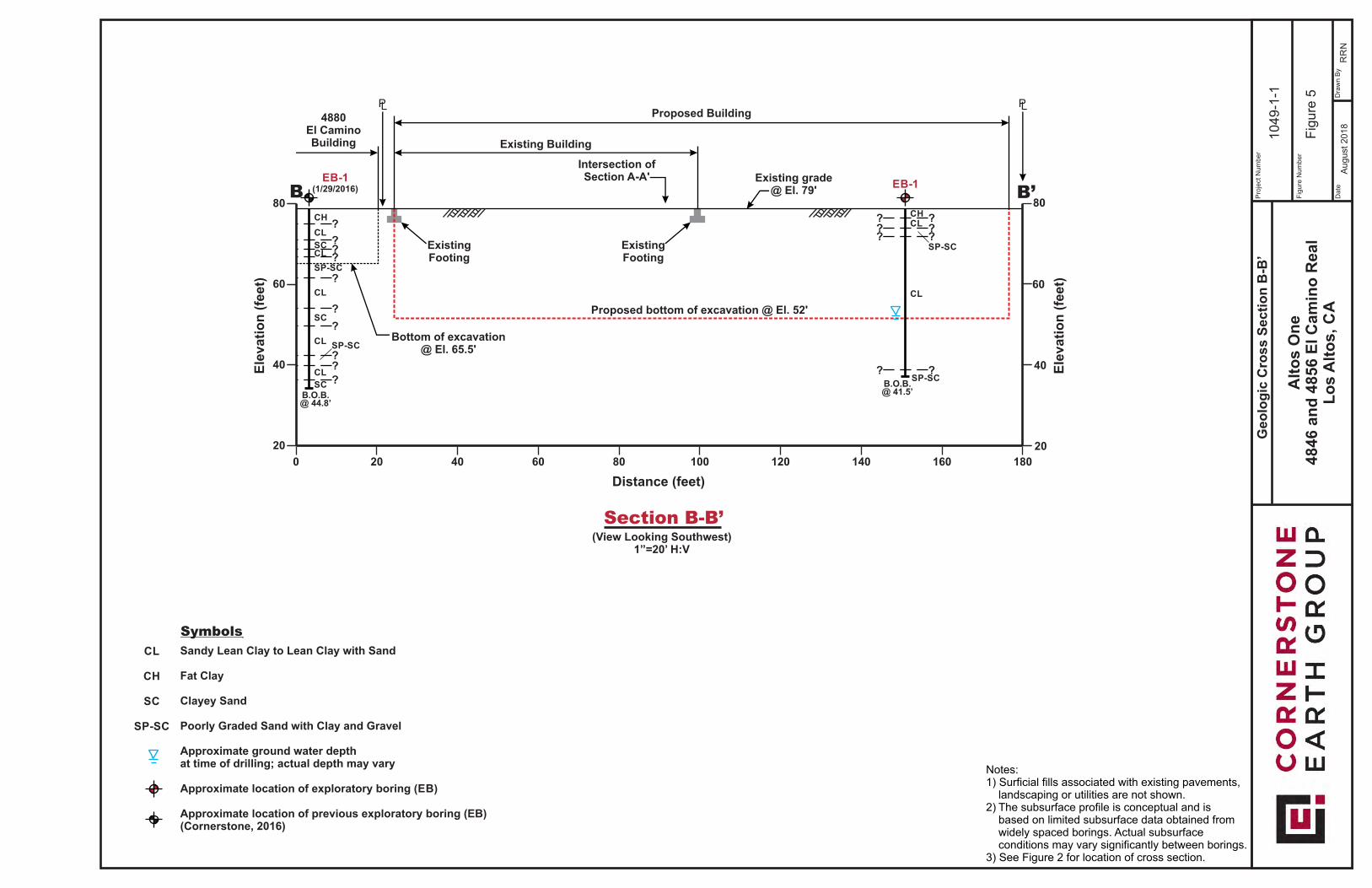
Pro
ject
Num
ber
Fig
ure
Num
ber
Date
Dra
wn B
y
Fig
ure
5
RR
N
1049-1
-1
Alt
os O
ne
4846 a
nd
4856 E
l C
am
ino
Real
Lo
s A
lto
s,
CA
August
2018
Geo
log
ic C
ross S
ecti
on
B-B
’
Notes:1) Surficial fills associated with existing pavements, landscaping or utilities are not shown.2) The subsurface profile is conceptual and is based on limited subsurface data obtained from widely spaced borings. Actual subsurface conditions may vary significantly between borings.3) See Figure 2 for location of cross section.
Sandy Lean Clay to Lean Clay with Sand
Fat Clay
Clayey Sand
Poorly Graded Sand with Clay and Gravel
Approximate ground water depth at time of drilling; actual depth may vary
Approximate location of exploratory boring (EB)
Approximate location of previous exploratory boring (EB)(Cornerstone, 2016)
CL
CH
SC
SP-SC
Symbols
(View Looking Southwest)1”=20’ H:V
Section B-B’
B.O.B. @ 44.8’
EB-1(1/29/2016)
Existing Building
Proposed Building
Proposed bottom of excavation @ El. 52'
Existing grade@ El. 79'
? ?
? ?? ?? ?
? ?
? ?
? ?
? ?? ?? ?
CH
CL
SCCL
SP-SC
CL
SC
CL SP-SC
CL
SC B.O.B. @ 41.5’
EB-1
? ?? ?? ?
? ?
CHCL
SP-SC
CL
SP-SC
4880El CaminoBuilding
Bottom of excavation@ El. 65.5'
PL PL
Intersection ofSection A-A'
ExistingFooting
ExistingFooting
60
40
20
0 20 40 60 80 100 140 160
Distance (feet)
Ele
vati
on
(fe
et)
80
60
40
20
120
B B’80
180
Ele
vati
on
(fe
et)

ALTOS ONE 1049-1-1
Page A-1
APPENDIX A: FIELD INVESTIGATION The field investigation consisted of a surface reconnaissance and a subsurface exploration program using truck-mounted, hollow-stem auger drilling equipment. Two 8-inch-diameter exploratory borings were drilled on July 13, 2018 to depths of 41½ to 45 feet. The approximate locations of exploratory borings are shown on the Site Plan, Figure 2. The soils encountered were continuously logged in the field by our representative and described in accordance with the Unified Soil Classification System (ASTM D2488). Boring logs, as well as a key to the classification of the soil and bedrock, are included as part of this appendix. Boring locations were approximated using existing site boundaries and other site features as references. Boring elevations were not determined. The locations of the borings should be considered accurate only to the degree implied by the method used. Representative soil samples were obtained from the borings at selected depths. All samples were returned to our laboratory for evaluation and appropriate testing. The standard penetration resistance blow counts were obtained by dropping a 140-pound hammer through a 30-inch free fall. The 2-inch O.D. split-spoon sampler was driven 18 inches and the number of blows was recorded for each 6 inches of penetration (ASTM D1586). 2.5-inch I.D. samples were obtained using a Modified California Sampler driven into the soil with the 140-pound hammer previously described. Unless otherwise indicated, the blows per foot recorded on the boring log represent the accumulated number of blows required to drive the last 12 inches. The various samplers are denoted at the appropriate depth on the boring logs. Field tests included an evaluation of the unconfined compressive strength of the soil samples using a pocket penetrometer device. The results of these tests are presented on the individual boring logs at the appropriate sample depths. Attached boring logs and related information depict subsurface conditions at the locations indicated and on the date designated on the logs. Subsurface conditions at other locations may differ from conditions occurring at these boring locations. The passage of time may result in altered subsurface conditions due to environmental changes. In addition, any stratification lines on the logs represent the approximate boundary between soil types and the transition may be gradual.
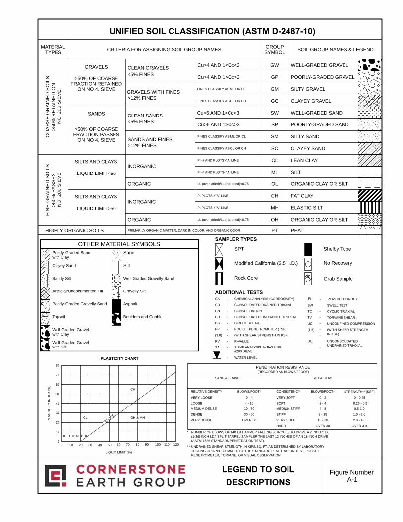
Poorly-Graded Gravelly Sand
>50% OF COARSEFRACTION PASSES
ON NO 4. SIEVE
WELL-GRADED GRAVEL
POORLY-GRADED GRAVEL
SILTY GRAVEL
CLAYEY GRAVEL
WELL-GRADED SAND
POORLY-GRADED SAND
SILTY SAND
CLAYEY SAND
LEAN CLAY
SILT
ORGANIC CLAY OR SILT
FAT CLAY
ELASTIC SILT
ORGANIC CLAY OR SILT
*
NUMBER OF BLOWS OF 140 LB HAMMER FALLING 30 INCHES TO DRIVE A 2 INCH O.D.
(1-3/8 INCH I.D.) SPLIT-BARREL SAMPLER THE LAST 12 INCHES OF AN 18-INCH DRIVE
(ASTM-1586 STANDARD PENETRATION TEST).
*
Modified California (2.5" I.D.)
Well-Graded Gravelwith Clay
-
-
-
-
-
Boulders and Cobble
Artificial/Undocumented Fill
Asphalt
GW
GP
GM
GC
SW
SP
SM
SC
CL
ML
OL
CH
MH
OH
Well-Graded Gravelwith Silt -
CLEAN GRAVELS
<5% FINES
GRAVELS WITH FINES
PRIMARILY ORGANIC MATTER, DARK IN COLOR, AND ORGANIC ODOR
>12% FINES
* UNDRAINED SHEAR STRENGTH IN KIPS/SQ. FT. AS DETERMINED BY LABORATORY
TESTING OR APPROXIMATED BY THE STANDARD PENETRATION TEST, POCKET
PENETROMETER, TORVANE, OR VISUAL OBSERVATION.
Well Graded Gravelly Sand
ADDITIONAL TESTSGravelly Silt
HIGHLY ORGANIC SOILS
CO
AR
SE
-GR
AIN
ED
SO
ILS
>5
0%
RE
TA
INE
DO
N
NO
.2
00
SIE
VE
FIN
E-G
RA
INE
DS
OIL
S
>5
0%
PA
SS
ES
NO
.2
00
SIE
VE
"A" LIN
E
PEAT
SILTS AND CLAYS
LIQUID LIMIT<50
SILTS AND CLAYS
Clayey Sand
LIQUID LIMIT>50
Silt
Sand
OTHER MATERIAL SYMBOLS
LIQUID LIMIT (%)
CH
CL OH & MH
-
-
CLEAN SANDS
<5% FINES
SANDS AND FINES
>12% FINES
INORGANIC
>50% OF COARSEFRACTION RETAINED
ON NO 4. SIEVE
SOIL GROUP NAMES & LEGEND
SWELL TEST
CYCLIC TRIAXIAL
TORVANE SHEAR
UNCONFINED COMPRESSION
PLASTICITY CHART
CL-ML
SANDS
No Recovery
PLASTICITY INDEX
0 - 0.25
0.25 - 0.5
0.5-1.0
1.0 - 2.0
2.0 - 4.0
OVER 4.0
(RECORDED AS BLOWS / FOOT)
VERY SOFT
SOFT
MEDIUM STIFF
STIFF
VERY STIFF
HARD
0 - 2
2 - 4
4 - 8
8 - 15
15 - 30
OVER 30
0 - 4
4 - 10
10 - 30
30 - 50
OVER 50
SILT & CLAY
PENETRATION RESISTANCE
SAND & GRAVEL
VERY LOOSE
LOOSE
MEDIUM DENSE
DENSE
VERY DENSE
PT
WATER LEVEL
BLOWS/FOOT*CONSISTENCYBLOWS/FOOT*RELATIVE DENSITY
Topsoil
PLA
ST
ICIT
YIN
DE
X(%
)
Sandy Silt
Poorly-Graded Sandwith Clay
UNIFIED SOIL CLASSIFICATION (ASTM D-2487-10)
Figure NumberA-1
FINES CLASSIFY AS ML OR CL
FINES CLASSIFY AS CL OR CH
PI>7 AND PLOTS>"A" LINE
PI>4 AND PLOTS<"A" LINE
LL (oven dried)/LL (not dried)<0.75
PI PLOTS >"A" LINE
PI PLOTS <"A" LINE
LL (oven dried)/LL (not dried)<0.75
0
10
20
30
40
50
60
70
80
Cu>4 AND 1<Cc<3
Cu>4 AND 1>Cc>3
FINES CLASSIFY AS ML OR CL
FINES CLASSIFY AS CL OR CH
Cu>6 AND 1<Cc<3
Cu>6 AND 1>Cc>3
ORGANIC
INORGANIC
ORGANIC
GRAVELS
0
-
-
-
-
-
-
-
-
-
CHEMICAL ANALYSIS (CORROSIVITY)
CONSOLIDATED DRAINED TRIAXIAL
CONSOLIDATION
CONSOLIDATED UNDRAINED TRIAXIAL
DIRECT SHEAR
POCKET PENETROMETER (TSF)
(WITH SHEAR STRENGTH IN KSF)
R-VALUE
SIEVE ANALYSIS: % PASSING
#200 SIEVE
MATERIALTYPES
CRITERIA FOR ASSIGNING SOIL GROUP NAMESGROUPSYMBOL
CA
CD
CN
CU
DS
PP
(3.0)
RV
SA
Shelby Tube
LEGEND TO SOIL
DESCRIPTIONS
UU UNCONSOLIDATED
UNDRAINED TRIAXIAL
(WITH SHEAR STRENGTH
IN KSF)
SW
TC
TV
UC
(1.5)
PI
SAMPLER TYPES
SPT
STRENGTH** (KSF)
Rock Core Grab Sample
10 20 30 40 50 60 70 80 90 100 110 120
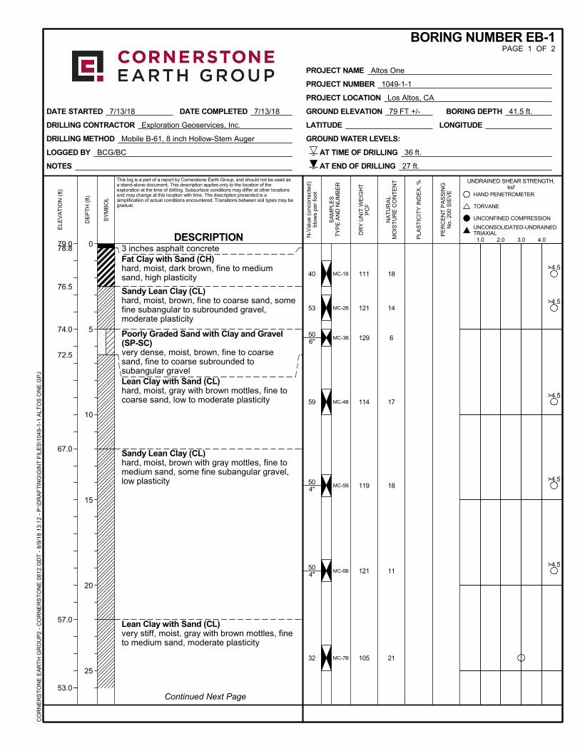
78.8
76.5
74.0
72.5
67.0
57.0
MC-1B
MC-2B
MC-3B
MC-4B
MC-5B
MC-6B
MC-7B
111
121
129
114
119
121
105
3 inches asphalt concreteFat Clay with Sand (CH)hard, moist, dark brown, fine to mediumsand, high plasticity
Sandy Lean Clay (CL)hard, moist, brown, fine to coarse sand, somefine subangular to subrounded gravel,moderate plasticity
Poorly Graded Sand with Clay and Gravel(SP-SC)very dense, moist, brown, fine to coarsesand, fine to coarse subrounded tosubangular gravelLean Clay with Sand (CL)hard, moist, gray with brown mottles, fine tocoarse sand, low to moderate plasticity
Sandy Lean Clay (CL)hard, moist, brown with gray mottles, fine tomedium sand, some fine subangular gravel,low plasticity
Lean Clay with Sand (CL)very stiff, moist, gray with brown mottles, fineto medium sand, moderate plasticity
18
14
6
17
18
11
21
40
53
506"
59
504"
504"
32
NOTES
LOGGED BY BCG/BC
DRILLING METHOD Mobile B-61, 8 inch Hollow-Stem Auger
DRILLING CONTRACTOR Exploration Geoservices, Inc.
GROUND WATER LEVELS:
DATE STARTED 7/13/18 DATE COMPLETED 7/13/18 BORING DEPTH 41.5 ft.GROUND ELEVATION 79 FT +/-
AT TIME OF DRILLING 36 ft.
AT END OF DRILLING 27 ft.
LATITUDE LONGITUDE
UNCONFINED COMPRESSIONSY
MB
OL
Continued Next Page53.0
79.0
ELE
VA
TIO
N (
ft)
PROJECT NAME Altos One
PROJECT NUMBER 1049-1-1
PROJECT LOCATION Los Altos, CA
BORING NUMBER EB-1PAGE 1 OF 2
This log is a part of a report by Cornerstone Earth Group, and should not be used asa stand-alone document. This description applies only to the location of theexploration at the time of drilling. Subsurface conditions may differ at other locationsand may change at this location with time. The description presented is asimplification of actual conditions encountered. Transitions between soil types may begradual.
UNDRAINED SHEAR STRENGTH,ksf
SA
MP
LES
TY
PE
AN
D N
UM
BE
R
DE
PT
H (
ft)
0
5
10
15
20
25
DR
Y U
NIT
WE
IGH
TP
CF TORVANE
1.0 2.0 3.0 4.0
HAND PENETROMETER
DESCRIPTION
NA
TU
RA
LM
OIS
TU
RE
CO
NT
EN
T
PLA
ST
ICIT
Y IN
DE
X, %
PE
RC
EN
T P
AS
SIN
GN
o. 2
00 S
IEV
E
N-V
alue
(un
corr
ecte
d)bl
ows
per
foot
CO
RN
ER
ST
ON
E E
AR
TH
GR
OU
P2
- C
OR
NE
RS
TO
NE
081
2.G
DT
- 8
/9/1
8 13
:12
- P
:\DR
AF
TIN
G\G
INT
FIL
ES
\104
9-1
-1 A
LTO
S O
NE
.GP
J
>4.5
>4.5
>4.5
>4.5
>4.5
UNCONSOLIDATED-UNDRAINEDTRIAXIAL

52.0
44.0
38.037.5
MC-8B
MC-9B
SPT-10B
116
103
Sandy Lean Clay (CL)very stiff, moist, gray with brown mottles, fineto coarse sand, some fine subangular gravel,low plasticity
Lean Clay with Sand (CL)very stiff, moist, gray with brown mottles, fineto medium sand, moderate plasticity
Poorly Graded Sand with Clay and Gravel(SP-SC)very dense, moist, brown, fine to coarsesand, fine to coarse subangular tosubrounded gravel
Bottom of Boring at 41.5 feet.
18
24
12
43
25
71
UNCONFINED COMPRESSIONSY
MB
OL
53.0
ELE
VA
TIO
N (
ft)
PROJECT NAME Altos One
PROJECT NUMBER 1049-1-1
PROJECT LOCATION Los Altos, CA
BORING NUMBER EB-1PAGE 2 OF 2
This log is a part of a report by Cornerstone Earth Group, and should not be used asa stand-alone document. This description applies only to the location of theexploration at the time of drilling. Subsurface conditions may differ at other locationsand may change at this location with time. The description presented is asimplification of actual conditions encountered. Transitions between soil types may begradual.
UNDRAINED SHEAR STRENGTH,ksf
SA
MP
LES
TY
PE
AN
D N
UM
BE
R
DE
PT
H (
ft)
30
35
40
45
50
55
DR
Y U
NIT
WE
IGH
TP
CF TORVANE
1.0 2.0 3.0 4.0
HAND PENETROMETER
DESCRIPTION
NA
TU
RA
LM
OIS
TU
RE
CO
NT
EN
T
PLA
ST
ICIT
Y IN
DE
X, %
PE
RC
EN
T P
AS
SIN
GN
o. 2
00 S
IEV
E
N-V
alue
(un
corr
ecte
d)bl
ows
per
foot
CO
RN
ER
ST
ON
E E
AR
TH
GR
OU
P2
- C
OR
NE
RS
TO
NE
081
2.G
DT
- 8
/9/1
8 13
:12
- P
:\DR
AF
TIN
G\G
INT
FIL
ES
\104
9-1
-1 A
LTO
S O
NE
.GP
J
UNCONSOLIDATED-UNDRAINEDTRIAXIAL

78.878.4
76.5
67.0
60.0
59.0
MC-1B
MC-2B
MC-3B
MC-4C
MC-5B
MC-6B
MC-7B
115
102
128
123
124
119
109
2 inches asphalt concrete over 5 inchesaggregate baseClayey Sand with Gravel (SC)dense, moist, brown, fine to coarse sand, finesubrounded to subangular gravelClayey Sand (SC)very dense, moist, brown, fine to coarsesand, some fine subrounded to subangulargravel
Poorly Graded Sand with Clay and Gravel(SP-SC)very dense, moist, brown, fine to coarsesand, fine to coarse subrounded tosubangular gravel
Sandy Lean Clay (CL)hard, moist, brown, fine to coarse sand, somefine subangular to subrounded gravel, lowplasticityLean Clay with Sand (CL)hard, moist, gray with brown mottles, fine tomedium sand, some fine subangular gravel,moderate plasticity
12
10
5
14
7
17
21
54
85
504"
505"
506"
66
44
NOTES
LOGGED BY BCG
DRILLING METHOD Mobile B-61, 8 inch Hollow-Stem Auger
DRILLING CONTRACTOR Exploration Geoservices, Inc.
GROUND WATER LEVELS:
DATE STARTED 7/13/18 DATE COMPLETED 7/13/18 BORING DEPTH 44.9 ft.GROUND ELEVATION 79 FT +/-
AT TIME OF DRILLING 32 ft.
AT END OF DRILLING 26 ft.
LATITUDE LONGITUDE
UNCONFINED COMPRESSIONSY
MB
OL
Continued Next Page53.0
79.0
ELE
VA
TIO
N (
ft)
PROJECT NAME Altos One
PROJECT NUMBER 1049-1-1
PROJECT LOCATION Los Altos, CA
BORING NUMBER EB-2PAGE 1 OF 2
This log is a part of a report by Cornerstone Earth Group, and should not be used asa stand-alone document. This description applies only to the location of theexploration at the time of drilling. Subsurface conditions may differ at other locationsand may change at this location with time. The description presented is asimplification of actual conditions encountered. Transitions between soil types may begradual.
UNDRAINED SHEAR STRENGTH,ksf
SA
MP
LES
TY
PE
AN
D N
UM
BE
R
DE
PT
H (
ft)
0
5
10
15
20
25
DR
Y U
NIT
WE
IGH
TP
CF TORVANE
1.0 2.0 3.0 4.0
HAND PENETROMETER
DESCRIPTION
NA
TU
RA
LM
OIS
TU
RE
CO
NT
EN
T
PLA
ST
ICIT
Y IN
DE
X, %
PE
RC
EN
T P
AS
SIN
GN
o. 2
00 S
IEV
E
N-V
alue
(un
corr
ecte
d)bl
ows
per
foot
CO
RN
ER
ST
ON
E E
AR
TH
GR
OU
P2
- C
OR
NE
RS
TO
NE
081
2.G
DT
- 8
/9/1
8 13
:12
- P
:\DR
AF
TIN
G\G
INT
FIL
ES
\104
9-1
-1 A
LTO
S O
NE
.GP
J
>4.5
>4.5
UNCONSOLIDATED-UNDRAINEDTRIAXIAL
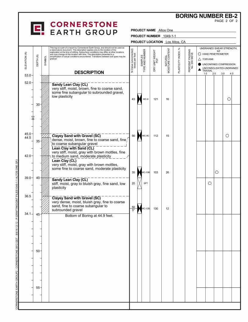
52.0
45.044.5
42.0
39.0
36.5
34.1
MC-8
MC-9C
MC-10B
SPT
MC-12B
121
112
103
130
Sandy Lean Clay (CL)very stiff, moist, brown, fine to coarse sand,some fine subangular to subrounded gravel,low plasticity
Clayey Sand with Gravel (SC)dense, moist, brown, fine to coarse sand, fineto coarse subangular gravelLean Clay with Sand (CL)very stiff, moist, gray with brown mottles, fineto medium sand, moderate plasticityLean Clay (CL)very stiff, moist, gray with brown mottles,some fine to coarse sand, moderate plasticity
Sandy Lean Clay (CL)stiff, moist, gray to bluish gray, fine sand, lowplasticity
Clayey Sand with Gravel (SC)very dense, moist, bluish gray, fine to coarsesand, fine to coarse subangular tosubrounded gravel
Bottom of Boring at 44.9 feet.
16
15
26
12
43
56
35
20
505"
UNCONFINED COMPRESSIONSY
MB
OL
53.0
ELE
VA
TIO
N (
ft)
PROJECT NAME Altos One
PROJECT NUMBER 1049-1-1
PROJECT LOCATION Los Altos, CA
BORING NUMBER EB-2PAGE 2 OF 2
This log is a part of a report by Cornerstone Earth Group, and should not be used asa stand-alone document. This description applies only to the location of theexploration at the time of drilling. Subsurface conditions may differ at other locationsand may change at this location with time. The description presented is asimplification of actual conditions encountered. Transitions between soil types may begradual.
UNDRAINED SHEAR STRENGTH,ksf
SA
MP
LES
TY
PE
AN
D N
UM
BE
R
DE
PT
H (
ft)
30
35
40
45
50
55
DR
Y U
NIT
WE
IGH
TP
CF TORVANE
1.0 2.0 3.0 4.0
HAND PENETROMETER
DESCRIPTION
NA
TU
RA
LM
OIS
TU
RE
CO
NT
EN
T
PLA
ST
ICIT
Y IN
DE
X, %
PE
RC
EN
T P
AS
SIN
GN
o. 2
00 S
IEV
E
N-V
alue
(un
corr
ecte
d)bl
ows
per
foot
CO
RN
ER
ST
ON
E E
AR
TH
GR
OU
P2
- C
OR
NE
RS
TO
NE
081
2.G
DT
- 8
/9/1
8 13
:12
- P
:\DR
AF
TIN
G\G
INT
FIL
ES
\104
9-1
-1 A
LTO
S O
NE
.GP
J
UNCONSOLIDATED-UNDRAINEDTRIAXIAL

ALTOS ONE 1049-1-1
Page B-1
APPENDIX B: LABORATORY TEST PROGRAM The laboratory testing program was performed to evaluate the physical and mechanical proerties of the soils retrieved from the site to aid in verifying soil classification. Moisture Content: The natural water content was determined (ASTM D2216) on 21 samples of the materials recovered from the borings. These water contents are recorded on the boring logs at the appropriate sample depths. Dry Densities: In place dry density determinations (ASTM D2937) were performed on 20 samples to measure the unit weight of the subsurface soils. Results of these tests are shown on the boring logs at the appropriate sample depths.
ALTOS ONE 1049-1-1
Page C-1
APPENDIX C: PREVIOUS FIELD EXPLORATIONS AND LABORATORY TESTING

Poorly-Graded Gravelly Sand
>50% OF COARSEFRACTION PASSES
ON NO 4. SIEVE
WELL-GRADED GRAVEL
POORLY-GRADED GRAVEL
SILTY GRAVEL
CLAYEY GRAVEL
WELL-GRADED SAND
POORLY-GRADED SAND
SILTY SAND
CLAYEY SAND
LEAN CLAY
SILT
ORGANIC CLAY OR SILT
FAT CLAY
ELASTIC SILT
ORGANIC CLAY OR SILT
*
NUMBER OF BLOWS OF 140 LB HAMMER FALLING 30 INCHES TO DRIVE A 2 INCH O.D.
(1-3/8 INCH I.D.) SPLIT-BARREL SAMPLER THE LAST 12 INCHES OF AN 18-INCH DRIVE
(ASTM-1586 STANDARD PENETRATION TEST).
*
Modified California (2.5" I.D.)
Well-Graded Gravelwith Clay
-
-
-
-
-
Boulders and Cobble
Artificial/Undocumented Fill
Asphalt
GW
GP
GM
GC
SW
SP
SM
SC
CL
ML
OL
CH
MH
OH
Well-Graded Gravelwith Silt -
CLEAN GRAVELS
<5% FINES
GRAVELS WITH FINES
PRIMARILY ORGANIC MATTER, DARK IN COLOR, AND ORGANIC ODOR
>12% FINES
* UNDRAINED SHEAR STRENGTH IN KIPS/SQ. FT. AS DETERMINED BY LABORATORY
TESTING OR APPROXIMATED BY THE STANDARD PENETRATION TEST, POCKET
PENETROMETER, TORVANE, OR VISUAL OBSERVATION.
Well Graded Gravelly Sand
ADDITIONAL TESTSGravelly Silt
HIGHLY ORGANIC SOILS
CO
AR
SE
-GR
AIN
ED
SO
ILS
>5
0%
RE
TA
INE
DO
N
NO
.2
00
SIE
VE
FIN
E-G
RA
INE
DS
OIL
S
>5
0%
PA
SS
ES
NO
.2
00
SIE
VE
"A" LIN
E
PEAT
SILTS AND CLAYS
LIQUID LIMIT<50
SILTS AND CLAYS
Clayey Sand
LIQUID LIMIT>50
Silt
Sand
OTHER MATERIAL SYMBOLS
LIQUID LIMIT (%)
CH
CL OH & MH
-
-
CLEAN SANDS
<5% FINES
SANDS AND FINES
>12% FINES
INORGANIC
>50% OF COARSEFRACTION RETAINED
ON NO 4. SIEVE
SOIL GROUP NAMES & LEGEND
SWELL TEST
CYCLIC TRIAXIAL
TORVANE SHEAR
UNCONFINED COMPRESSION
PLASTICITY CHART
CL-ML
SANDS
No Recovery
PLASTICITY INDEX
0 - 0.25
0.25 - 0.5
0.5-1.0
1.0 - 2.0
2.0 - 4.0
OVER 4.0
(RECORDED AS BLOWS / FOOT)
VERY SOFT
SOFT
MEDIUM STIFF
STIFF
VERY STIFF
HARD
0 - 2
2 - 4
4 - 8
8 - 15
15 - 30
OVER 30
0 - 4
4 - 10
10 - 30
30 - 50
OVER 50
SILT & CLAY
PENETRATION RESISTANCE
SAND & GRAVEL
VERY LOOSE
LOOSE
MEDIUM DENSE
DENSE
VERY DENSE
PT
WATER LEVEL
BLOWS/FOOT*CONSISTENCYBLOWS/FOOT*RELATIVE DENSITY
Topsoil
PLA
ST
ICIT
YIN
DE
X(%
)
Sandy Silt
Poorly-Graded Sandwith Clay
UNIFIED SOIL CLASSIFICATION (ASTM D-2487-10)
Figure NumberA-1
FINES CLASSIFY AS ML OR CL
FINES CLASSIFY AS CL OR CH
PI>7 AND PLOTS>"A" LINE
PI>4 AND PLOTS<"A" LINE
LL (oven dried)/LL (not dried)<0.75
PI PLOTS >"A" LINE
PI PLOTS <"A" LINE
LL (oven dried)/LL (not dried)<0.75
0
10
20
30
40
50
60
70
80
Cu>4 AND 1<Cc<3
Cu>4 AND 1>Cc>3
FINES CLASSIFY AS ML OR CL
FINES CLASSIFY AS CL OR CH
Cu>6 AND 1<Cc<3
Cu>6 AND 1>Cc>3
ORGANIC
INORGANIC
ORGANIC
GRAVELS
0
-
-
-
-
-
-
-
-
-
CHEMICAL ANALYSIS (CORROSIVITY)
CONSOLIDATED DRAINED TRIAXIAL
CONSOLIDATION
CONSOLIDATED UNDRAINED TRIAXIAL
DIRECT SHEAR
POCKET PENETROMETER (TSF)
(WITH SHEAR STRENGTH IN KSF)
R-VALUE
SIEVE ANALYSIS: % PASSING
#200 SIEVE
MATERIALTYPES
CRITERIA FOR ASSIGNING SOIL GROUP NAMESGROUPSYMBOL
CA
CD
CN
CU
DS
PP
(3.0)
RV
SA
Shelby Tube
LEGEND TO SOIL
DESCRIPTIONS
UU UNCONSOLIDATED
UNDRAINED TRIAXIAL
(WITH SHEAR STRENGTH
IN KSF)
SW
TC
TV
UC
(1.5)
PI
SAMPLER TYPES
SPT
STRENGTH** (KSF)
Rock Core Grab Sample
10 20 30 40 50 60 70 80 90 100 110 120

10
79.378.8
75.1
71.1
69.6
67.6
62.6
57.6
54.6
MC-1B
MC-2B
MC-3B
MC-4B
MC
MC-6B
MC
8A
MC
8B
14
16
10
7
7
19
18
103
110
110
123
124
102
112
3113
41
19
45
505"
36
21
13
3 inches asphalt concrete over 6 inchesaggregate baseFat Clay with Sand (CH)hard, moist, dark brown to brown, fine tomedium sand, high plasticityLiquid Limit = 51, Plastic Limit = 20
Sandy Lean Clay (CL)hard, moist, brown, fine to medium sand,some fine subangular to subrounded gravel,low plasticity
Clayey Sand with Gravel (SC)medium dense, moist, brown, fine to coarsesand, fine to coarse subangular tosubrounded gravelSandy Lean Clay (CL)hard, moist, brown with gray mottles, fine tomedium sand, some fine subangular tosubrounded gravel, low plasticityPoorly Graded Sand with Clay and Gravel(SP-SC)medium dense, moist, brown, fine to mediumsand, fine to coarse subangular tosubrounded gravel
Sandy Lean Clay (CL)very stiff, moist, brown, fine to medium sand,low plasticity
Lean Clay with Sand (CL)very stiff, moist, brown with gray mottles, fineto medium sand, moderate plasticity
NOTES
LOGGED BY MFR
DRILLING METHOD Mobile B-53, 8 inch Hollow-Stem Auger
DRILLING CONTRACTOR Exploration Geoservices, Inc.
GROUND WATER LEVELS:
DATE STARTED 1/29/16 DATE COMPLETED 1/29/16 BORING DEPTH 44.8 ft.GROUND ELEVATION 79.6 FT +/-
LATITUDE LONGITUDE
AT TIME OF DRILLING Not Encountered
AT END OF DRILLING Not Encountered
UNCONFINED COMPRESSION
PE
RC
EN
T P
AS
SIN
GN
o. 2
00 S
IEV
E
SY
MB
OL
Continued Next Page53.6
79.6
ELE
VA
TIO
N (
ft)
PROJECT NAME 4880 El Camino Real
PROJECT NUMBER 870-1-1
PROJECT LOCATION Los Altos, CA
BORING NUMBER EB-1PAGE 1 OF 2
This log is a part of a report by Cornerstone Earth Group, and should not be used asa stand-alone document. This description applies only to the location of theexploration at the time of drilling. Subsurface conditions may differ at other locationsand may change at this location with time. The description presented is asimplification of actual conditions encountered. Transitions between soil types may begradual.
UNDRAINED SHEAR STRENGTH,ksf
SA
MP
LES
TY
PE
AN
D N
UM
BE
R
DE
PT
H (
ft)
0
5
10
15
20
25
NA
TU
RA
LM
OIS
TU
RE
CO
NT
EN
T,
%
DR
Y U
NIT
WE
IGH
TP
CF
PLA
ST
ICIT
Y IN
DE
X, %
TORVANE
1.0 2.0 3.0 4.0
HAND PENETROMETER
N-V
alue
(un
corr
ecte
d)bl
ows
per
foot
DESCRIPTION
CO
RN
ER
ST
ON
E E
AR
TH
GR
OU
P2
- C
OR
NE
RS
TO
NE
081
2.G
DT
- 2
/25
/16
10:
06 -
P:\D
RA
FT
ING
\GIN
T F
ILE
S\8
70-1
-1 4
880
EL
CA
MIN
O R
EA
L.G
PJ
>4.5
>4.5
>4.5
>4.5
UNCONSOLIDATED-UNDRAINEDTRIAXIAL
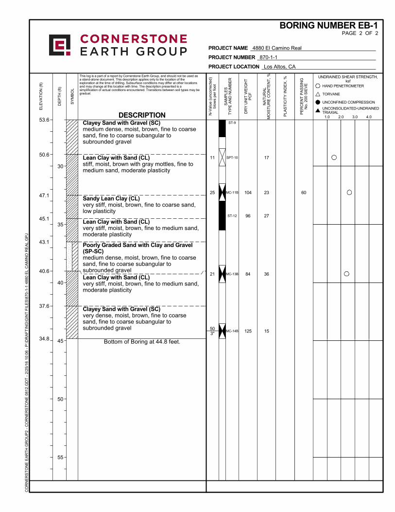
60
50.6
47.1
45.1
43.1
40.6
37.6
34.8
ST-9
SPT-10
MC-11B
ST-12
MC-13B
MC-14B
17
23
27
36
15
104
96
84
125
11
25
21
503"
Clayey Sand with Gravel (SC)medium dense, moist, brown, fine to coarsesand, fine to coarse subangular tosubrounded gravel
Lean Clay with Sand (CL)stiff, moist, brown with gray mottles, fine tomedium sand, moderate plasticity
Sandy Lean Clay (CL)very stiff, moist, brown, fine to coarse sand,low plasticity
Lean Clay with Sand (CL)very stiff, moist, brown, fine to medium sand,moderate plasticity
Poorly Graded Sand with Clay and Gravel(SP-SC)medium dense, moist, brown, fine to coarsesand, fine to coarse subangular tosubrounded gravelLean Clay with Sand (CL)very stiff, moist, brown, fine to medium sand,moderate plasticity
Clayey Sand with Gravel (SC)very dense, moist, brown, fine to coarsesand, fine to coarse subangular tosubrounded gravel
Bottom of Boring at 44.8 feet.
UNCONFINED COMPRESSION
PE
RC
EN
T P
AS
SIN
GN
o. 2
00 S
IEV
E
SY
MB
OL
53.6
ELE
VA
TIO
N (
ft)
PROJECT NAME 4880 El Camino Real
PROJECT NUMBER 870-1-1
PROJECT LOCATION Los Altos, CA
BORING NUMBER EB-1PAGE 2 OF 2
This log is a part of a report by Cornerstone Earth Group, and should not be used asa stand-alone document. This description applies only to the location of theexploration at the time of drilling. Subsurface conditions may differ at other locationsand may change at this location with time. The description presented is asimplification of actual conditions encountered. Transitions between soil types may begradual.
UNDRAINED SHEAR STRENGTH,ksf
SA
MP
LES
TY
PE
AN
D N
UM
BE
R
DE
PT
H (
ft)
30
35
40
45
50
55
NA
TU
RA
LM
OIS
TU
RE
CO
NT
EN
T,
%
DR
Y U
NIT
WE
IGH
TP
CF
PLA
ST
ICIT
Y IN
DE
X, %
TORVANE
1.0 2.0 3.0 4.0
HAND PENETROMETER
N-V
alue
(un
corr
ecte
d)bl
ows
per
foot
DESCRIPTION
CO
RN
ER
ST
ON
E E
AR
TH
GR
OU
P2
- C
OR
NE
RS
TO
NE
081
2.G
DT
- 2
/25
/16
10:
06 -
P:\D
RA
FT
ING
\GIN
T F
ILE
S\8
70-1
-1 4
880
EL
CA
MIN
O R
EA
L.G
PJ
UNCONSOLIDATED-UNDRAINEDTRIAXIAL

The reported coordinates were acquired from consumer grade GPS equipment and are only approximate locations. The coordinates should not be used for design purposes.
0 300 600
0
5
10
15
20
25
30
35
40
45
50
55
60
65
qt (tsf)
De
pth
(fe
et)
0.0 5.0 10.0
fs (tsf)
0 5 10
Rf (%)
0 100 2000
u (psi)
0 6 12
SBT
Cornerstone Earth GroupJob No: 16-56005
Date: 01:26:16 08:43
Site: 4880 El Camino Real
Sounding: CPT-01
Cone: 446:T1500F15U500
Max Depth: 18.300 m / 60.04 ftDepth Inc: 0.050 m / 0.164 ftAvg Int: Every Point
File: 16-56005_CP01.CORUnit Wt: SBT Zones
SBT: Robertson and Campanella, 1986Coords: UTM Zone 10N N: 4139411m E: 578836m
UndefinedSilty Sand/SandSilty Sand/SandSilt
Stiff Fine GrainedCemented SandSandSiltSiltSilty Sand/SandSiltSilty Sand/SandStiff Fine GrainedSandy Silt
Sand
Gravelly SandGravelly SandGravelly Sand
Gravelly SandSandSandSiltSiltSiltClayey SiltSiltClayClaySilty Sand/SandSandy SiltSandy SiltSandy SiltClayey SiltClayey SiltClayey SiltSilty ClaySilty ClaySilty Sand/Sand
Silty Sand/SandSandGravelly SandGravelly Sand
SiltClayey SiltSilty Sand/SandSiltSiltClayey SiltGravelly SandSandy Silt
Gravelly Sand
SandSilty Sand/SandSiltSilty Sand/Sand
SandSandSiltSandy Silt
Silt
Undefined
Target Depth Target Depth Target Depth Target Depth
Equilibrium Pore Pressure (Ueq) Assumed Ueq Hydrostatic LineDissipation, Ueq not achievedDissipation, Ueq achieved
Drill Out Drill Out Drill Out Drill Out
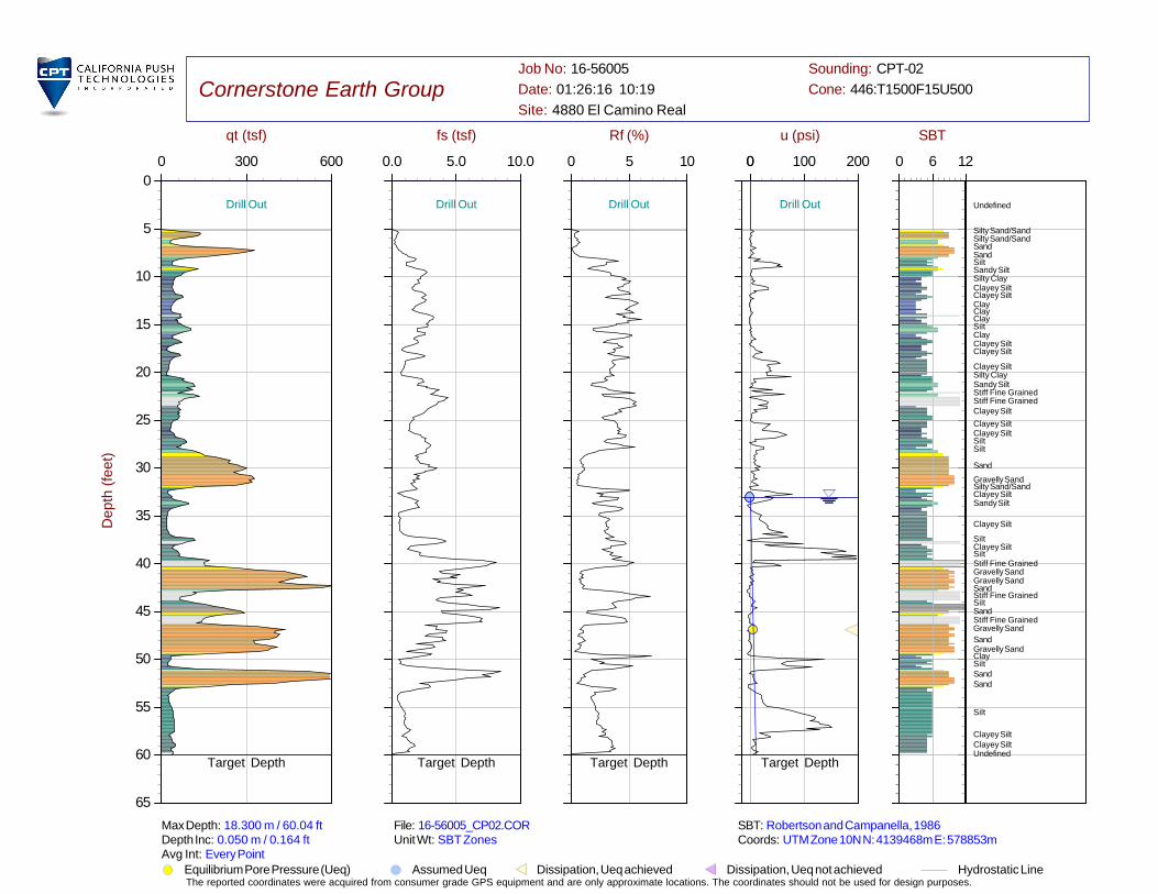
The reported coordinates were acquired from consumer grade GPS equipment and are only approximate locations. The coordinates should not be used for design purposes.
0 300 600
0
5
10
15
20
25
30
35
40
45
50
55
60
65
qt (tsf)
De
pth
(fe
et)
0.0 5.0 10.0
fs (tsf)
0 5 10
Rf (%)
0 100 2000
u (psi)
0 6 12
SBT
Cornerstone Earth GroupJob No: 16-56005
Date: 01:26:16 10:19
Site: 4880 El Camino Real
Sounding: CPT-02
Cone: 446:T1500F15U500
Max Depth: 18.300 m / 60.04 ftDepth Inc: 0.050 m / 0.164 ftAvg Int: Every Point
File: 16-56005_CP02.CORUnit Wt: SBT Zones
SBT: Robertson and Campanella, 1986Coords: UTM Zone 10N N: 4139468m E: 578853m
Undefined
Silty Sand/SandSilty Sand/SandSandSandSiltSandy SiltSilty ClayClayey SiltClayey SiltClayClayClaySiltClayClayey SiltClayey Silt
Clayey SiltSilty ClaySandy SiltStiff Fine GrainedStiff Fine GrainedClayey Silt
Clayey SiltClayey SiltSiltSilt
Sand
Gravelly SandSilty Sand/SandClayey SiltSandy Silt
Clayey Silt
SiltClayey SiltSiltStiff Fine GrainedGravelly SandGravelly SandSandStiff Fine GrainedSiltSandStiff Fine GrainedGravelly Sand
SandGravelly SandClaySiltSandSand
Silt
Clayey SiltClayey SiltUndefined
Target Depth Target Depth Target Depth Target Depth
Equilibrium Pore Pressure (Ueq) Assumed Ueq Hydrostatic LineDissipation, Ueq not achievedDissipation, Ueq achieved
Drill Out Drill Out Drill Out Drill Out
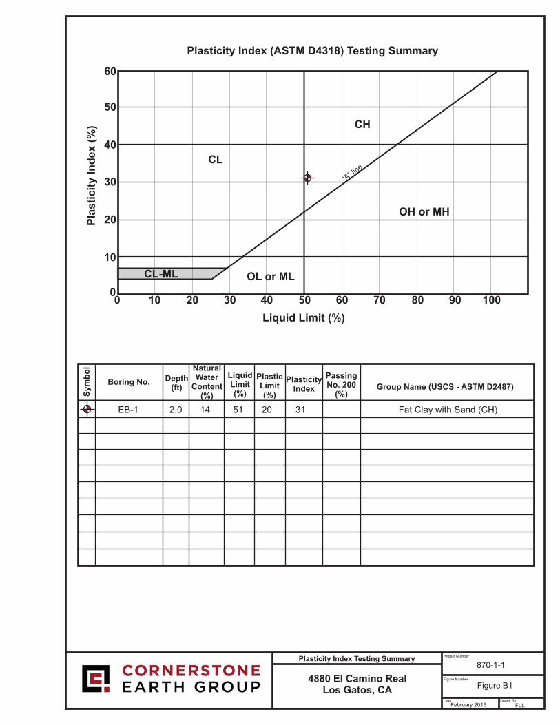
4880 El Camino RealLos Gatos, CA
Project Number
Figure Number
Date Drawn By
870-1-1
Figure B1
February 2016 FLL
Plasticity Index Testing Summary
60
0
10
20
30
40
50
0 100908070605040302010
CL ML- OL MLor
OH MHor
CH
CL
Pla
sti
cit
y In
dex (
%)
Liquid Limit (%)
Group Name ( - D2487)USCS ASTMBoring No.
Sym
bo
l
Depth(ft)
NaturalWater
Content(%)
LiquidLimit(%)
PlasticLimit(%)
PlasticityIndex
PassingNo. 200
(%)
“A” lin
e
Plasticity Index ( D4318) Testing SummaryASTM
Fat Clay with Sand (CH)31EB-1 51 20142.0
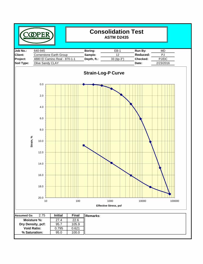
Job No.: Boring: Run By: MDClient: Sample: Reduced: PJProject: Depth, ft.: Checked: PJ/DCSoil Type: Date: 2/23/2016
EB-112
33 (tip-3")4880 El Camino Real - 870-1-1Cornerstone Earth Group640-945
Olive Sandy CLAY
0.0
2.0
4.0
6.0
8.0
%
Strain-Log-P Curve
Consolidation TestASTM D2435
Assumed Gs 2.75 Initial Final27.4 22.695.7 105.90.795 0.62195.0 100.0
Void Ratio:% Saturation:
Dry Density, pcf: Moisture %:
10.0
12.0
14.0
16.0
18.0
20.010 100 1000 10000 100000
Stra
in,
Effective Stress, psf
Remarks:
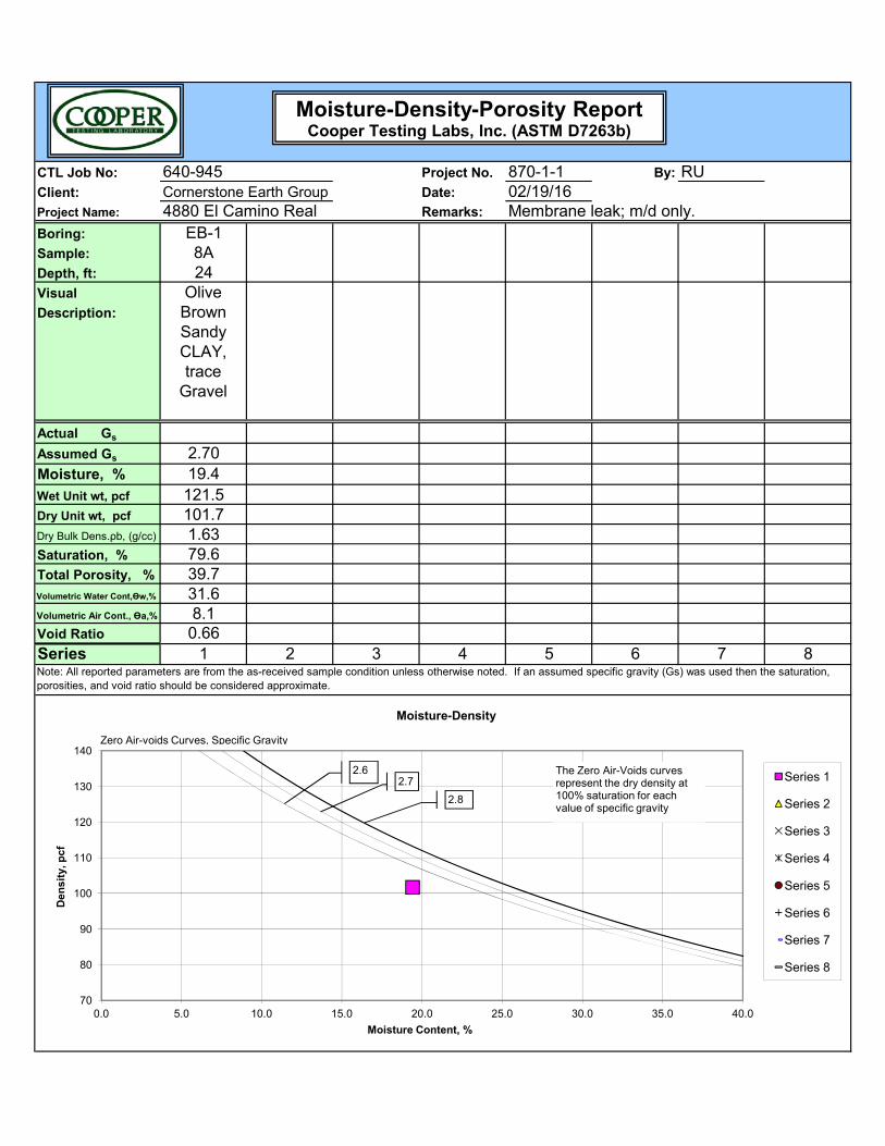
CTL Job No: Project No. 870-1-1 By: RUClient: Date: 02/19/16Project Name: Remarks:
Boring: EB-1Sample: 8ADepth, ft: 24Visual
Description:
Actual Gs
Assumed Gs 2.70Moisture, % 19.4Wet Unit wt, pcf 121.5Dry Unit wt, pcf 101.7Dry Bulk Dens.ρb, (g/cc) 1.63Saturation, % 79.6
Olive Brown Sandy CLAY, trace
Gravel
Cornerstone Earth Group640-945
Membrane leak; m/d only.4880 El Camino Real
Moisture-Density-Porosity ReportCooper Testing Labs, Inc. (ASTM D7263b)
Saturation, % 79.6Total Porosity, % 39.7Volumetric Water Cont,Өw,% 31.6Volumetric Air Cont., Өa,% 8.1Void Ratio 0.66Series 1 2 3 4 5 6 7 8Note: All reported parameters are from the as-received sample condition unless otherwise noted. If an assumed specific gravity (Gs) was used then the saturation, porosities, and void ratio should be considered approximate.
70
80
90
100
110
120
130
140
0.0 5.0 10.0 15.0 20.0 25.0 30.0 35.0 40.0
Den
sity
, pcf
Moisture Content, %
Moisture-Density
Series 1
Series 2
Series 3
Series 4
Series 5
Series 6
Series 7
Series 8
Zero Air-voids Curves, Specific Gravity
2.62.7
2.8
The Zero Air-Voids curves represent the dry density at 100% saturation for each value of specific gravity
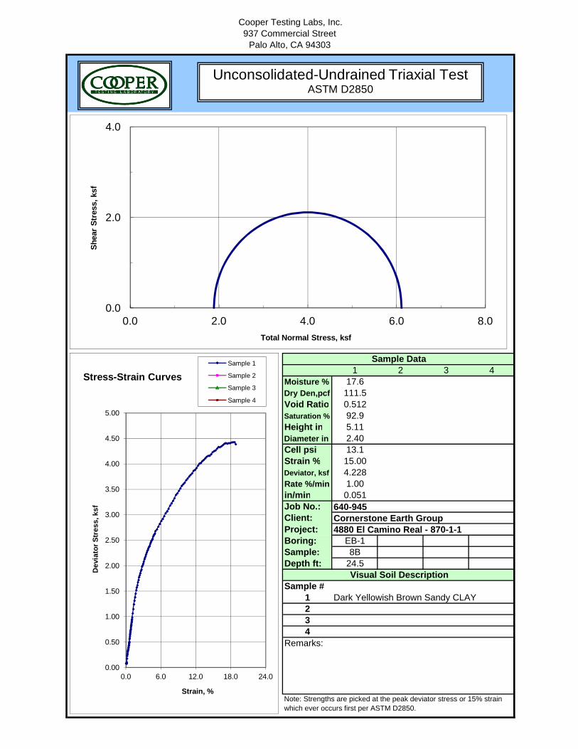
Cooper Testing Labs, Inc.937 Commercial Street
Palo Alto, CA 94303
1 2 3 4Moisture % 17.6Dry Den,pcf 111.5Void Ratio 0.512Saturation % 92.9Height in 5.11Diameter in 2.40Cell psi 13.1Strain % 15.00Deviator, ksf 4.228Rate %/min 1.00in/min 0.051Job No.:Client:Project:Boring: EB-1Sample: 8BDepth ft: 24.5
Sample #1234
Note: Strengths are picked at the peak deviator stress or 15% strain which ever occurs first per ASTM D2850.
Remarks:
Sample Data
Visual Soil Description
Dark Yellowish Brown Sandy CLAY
640-945Cornerstone Earth Group4880 El Camino Real - 870-1-1
0.0
2.0
4.0
0.0 2.0 4.0 6.0 8.0
Shea
r Str
ess,
ksf
Total Normal Stress, ksf
0.00
0.50
1.00
1.50
2.00
2.50
3.00
3.50
4.00
4.50
5.00
0.0 6.0 12.0 18.0 24.0
Dev
iato
r Str
ess,
ksf
Strain, %
Stress-Strain CurvesSample 1
Sample 2
Sample 3
Sample 4
Unconsolidated-Undrained Triaxial TestASTM D2850