Embed Size (px)
Citation preview

Prepared By : MOHD. KHAIRI
RECOMMENDATIONSFINDING
14’’ Residual Fuel Oil No. 6
Inside Terminal – Outside pump area*Please refer Appendix 3 for detail location
Corrosion under wrapping was noted at soil to air interface area due to wrap failure and gives a path towater ingress inside, marked as location 1 in ISOdrawing. No sign of corrosion propagate deeper after thewrapping end.*Please refer Appendix 2 for ½ remaining life calculation at pits area.
Consideration to perform permanent repair at this area with remove the corrosion, restore with weld metal deposited/insert weld patch, apply coal tar enamel and re-wrap with proper procedure and suitable wrapping for buried piping up to 6’’ from soil to air interface.
LINE SERVICE DRAWING REFERENCE
DESCRIPTION LOCATION
ISO drawing no. 20
Circuit 4 - Tango line
VISUAL INSPECTION FINDINGS AND RECOMMENDATIONSWITH PHOTOGRAPHS
VITAL ENERGY, GUAM, U.S.A PHOTO NO. : 4
Location 1
Max. pits depth = 0.17’’
114

Prepared By : MOHD. KHAIRI
RECOMMENDATIONSFINDING
14’’ Residual Fuel Oil No. 6
Inside Terminal – Outside pump area*Please refer Appendix 3 for detail location
Corrosion was noted at contact area betweenpiping and support, marked as locations 2 to 5 in ISO drawing.*Please refer Appendix 2 for ½ remaining life calculation at pits area.
To lift the piping and consideration to perform permanent repair at this area with remove the corrosion, restore with weld metal deposited/insert weld patch, follow by NDE and re-painting as per client’s specification.Note:-Pits depth measurement at contact area between piping and support based on estimation due to inaccessible area.
LINE SERVICE DRAWING REFERENCE
DESCRIPTION LOCATION
ISO drawing no. 20
Circuit 4 - Tango line
VISUAL INSPECTION FINDINGS AND RECOMMENDATIONSWITH PHOTOGRAPHS
VITAL ENERGY, GUAM, U.S.A PHOTO NO. : 5
Location 2
Max. pits depth = 0.13’’
Location 3
Max. pits depth = 0.20’’
Location 4
Max. pits depth = 0.22’’
Location 5
Max. pits depth = 0.20’’
115

Prepared By : MOHD. KHAIRI
RECOMMENDATIONSFINDING
14’’ Residual Fuel Oil No. 6
Inside Terminal – Outside pump area*Please refer Appendix 3 for detail location
Temporary repair was noted at bottom section of piping.According to API 570 paragraph 8.1.4.1, the design of temporary enclosures and repair shall be approved by pipingengineer and temporary repairs should be removed and replaced with a suitable permanent repair at the next available maintenance opportunity.
Consideration to perform permanent repair in accordance to API 570, restore with weld metal deposited/insert weld patch follows by NDE and painting asper client’s specification.
LINE SERVICE DRAWING REFERENCE
DESCRIPTION LOCATION
ISO drawing no. 20
Circuit 4 - Tango line
VISUAL INSPECTION FINDINGS AND RECOMMENDATIONSWITH PHOTOGRAPHS
VITAL ENERGY, GUAM, U.S.A PHOTO NO. : 6
At support 5
At support 7
116

Prepared By : MOHD. KHAIRI
RECOMMENDATIONSFINDING
14’’ Residual Fuel Oil No. 6
Inside Terminal – Outside pump area*Please refer Appendix 3 for detail location
Corrosion was noted at contact area betweenpiping and support, marked as locations 6 to 9 in ISO drawing.*Please refer Appendix 2 for ½ remaining life calculation at pits area.
To lift the piping and consideration to perform permanent repair at location 8 and 9 with remove the corrosion, restore with weld metal deposited/insert weld patch, followby NDE and re-painting as per client’s specification. To perform surface preparation and follows with maintenance painting for location 6 and 7.Note:-Pits depth measurement at contact area between piping and support based on estimation due to inaccessible area.
LINE SERVICE DRAWING REFERENCE
DESCRIPTION LOCATION
ISO drawing no. 21
Circuit 4 - Tango line
VISUAL INSPECTION FINDINGS AND RECOMMENDATIONSWITH PHOTOGRAPHS
VITAL ENERGY, GUAM, U.S.A PHOTO NO. : 7
Location 6
Max. pits depth = 0.08’’
Location 7
Max. pits depth = 0.07’’
Location 8
Max. pits depth = 0.13’’
Location 9
Max. pits depth = 0.13’’
117

Prepared By : MOHD. KHAIRI
RECOMMENDATIONSFINDING
14’’ Residual Fuel Oil No. 6
Inside Terminal – Outside pump area*Please refer Appendix 3 for detail location
Corrosion was noted at contact area betweenpiping and support, marked as locations 10 to 13 in ISO drawing.*Please refer Appendix 2 for ½ remaining life calculation at pits area.
To lift the piping and perform surface preparation andfollows by maintenance painting as per client’s specification.Note:-Pits depth measurement at contact area between piping and support based on estimation due to inaccessible area.
LINE SERVICE DRAWING REFERENCE
DESCRIPTION LOCATION
ISO drawing no. 21
Circuit 4 - Tango line
VISUAL INSPECTION FINDINGS AND RECOMMENDATIONSWITH PHOTOGRAPHS
VITAL ENERGY, GUAM, U.S.A PHOTO NO. : 8
Location 10
Max. pits depth = 0.08’’
Location 11
Max. pits depth = 0.07’’
Location 12
Max. pits depth = 0.06’’
Location 13
Max. pits depth = 0.10’’
118

Prepared By : MOHD. KHAIRI
RECOMMENDATIONSFINDING
14’’ Residual Fuel Oil No. 6
Inside Terminal – Outside pump area*Please refer Appendix 3 for detail location
Corrosion was noted at contact area betweenpiping and support, marked as locations 14 to 17 in ISO drawing.*Please refer Appendix 2 for ½ remaining life calculation at pits area.
To lift the piping and perform surface preparation andfollows by maintenance painting as per client’s specification for location 14 and consideration to performpermanent repair at location 15 to 17 with remove the corrosion, restore with weld metal deposited/insert weld patch, follow by NDE and re-painting as per client’s specification.Note:-Pits depth measurement at contact area between piping and support based on estimation due to inaccessible area.
LINE SERVICE DRAWING REFERENCE
DESCRIPTION LOCATION
ISO drawing no. 22
Circuit 4 - Tango line
VISUAL INSPECTION FINDINGS AND RECOMMENDATIONSWITH PHOTOGRAPHS
VITAL ENERGY, GUAM, U.S.A PHOTO NO. : 9
Location 14
Max. pits depth = 0.08’’
Location 15
Max. pits depth = 0.22’’
Location 16
Max. pits depth = 0.20’’
Location 17
Max. pits depth = 0.13’’
119

Prepared By : MOHD. KHAIRI
RECOMMENDATIONSFINDING
14’’ Residual Fuel Oil No. 6
Inside Terminal – Outside pump area*Please refer Appendix 3 for detail location
1. Corrosion was noted at contact area betweenpiping and support, marked as location 18 in ISO drawing.2. Temporary repair was noted at bottom section of piping.According to API 570 paragraph 8.1.4.1, the design of temporary enclosures and repair shall be approved by pipingengineer and temporary repairs should be removed and replaced with a suitable permanent repair at the next available maintenance opportunity.*Please refer Appendix 2 for ½ remaining life calculation at pits area.
1. To lift the piping and consideration to perform permanent repair at this area with remove the corrosion, restore with weld metal deposited/insert weld patch, follow by NDE and re-painting as per client’s specification.2. Consideration to perform permanent repair in accordance to API 570, restore with weld metal deposited/insert weld patch follows by NDE and painting asper client’s specification.Note:-Pits depth measurement at contact area between piping and support based on estimation due to inaccessible area.
LINE SERVICE DRAWING REFERENCE
DESCRIPTION LOCATION
ISO drawing no. 22
Circuit 4 - Tango line
VISUAL INSPECTION FINDINGS AND RECOMMENDATIONSWITH PHOTOGRAPHS
VITAL ENERGY, GUAM, U.S.A PHOTO NO. : 10
Location 18
Max. pits depth = 0.13’’
Between support 20 & 21
120

Prepared By : MOHD. KHAIRI
RECOMMENDATIONSFINDING
14’’ Residual Fuel Oil No. 6
Inside Terminal – Outside pump area*Please refer Appendix 3 for detail location
Temporary repair was noted at bottom section of piping.According to API 570 paragraph 8.1.4.1, the design of temporary enclosures and repair shall be approved by pipingengineer and temporary repairs should be removed and replaced with a suitable permanent repair at the next available maintenance opportunity.
Consideration to perform permanent repair in accordance to API 570, restore with weld metal deposited/insert weld patch follows by NDE and painting as per client’s specification.
LINE SERVICE DRAWING REFERENCE
DESCRIPTION LOCATION
ISO drawing no. 22
Circuit 4 - Tango line
VISUAL INSPECTION FINDINGS AND RECOMMENDATIONSWITH PHOTOGRAPHS
VITAL ENERGY, GUAM, U.S.A PHOTO NO. : 11
Between support 21 & 22 At support 23
At support 24 At support 26
121

Prepared By : MOHD. KHAIRI
RECOMMENDATIONSFINDING
14’’ Residual Fuel Oil No. 6
Inside Terminal – Outside pump area*Please refer Appendix 3 for detail location
Corrosion was noted at contact area between piping andsupport, marked as locations 19 and 20 in ISO drawing.*Please refer Appendix 2 for ½ remaining life calculation at pits area.
To lift the piping and perform surface preparation andfollows by maintenance painting as per client’s specification for location 20 and consideration to perform permanent repair at location 19 with remove the corrosion,restore with weld metal deposited/insert weld patch, followby NDE and re-painting as per client’s specification.Note:-Pits depth measurement at contact area between piping and support based on estimation due to inaccessible area.
LINE SERVICE DRAWING REFERENCE
DESCRIPTION LOCATION
ISO drawing no. 23
Circuit 4 - Tango line
VISUAL INSPECTION FINDINGS AND RECOMMENDATIONSWITH PHOTOGRAPHS
VITAL ENERGY, GUAM, U.S.A PHOTO NO. : 12
Location 19
Location 20
Max. pits depth = 0.18’’
Max. pits depth = 0.08’’
122

Prepared By : MOHD. KHAIRI
RECOMMENDATIONSFINDING
14’’ Residual Fuel Oil No. 6
Inside Terminal – Outside pump area*Please refer Appendix 3 for detail location
1. Temporary repair was noted at bottom section of piping.According to API 570 paragraph 8.1.4.1, the design of temporary enclosures and repair shall be approved by pipingengineer and temporary repairs should be removed and replaced with a suitable permanent repair at the next available maintenance opportunity.2. Wrapping tape was observed intact, no sign of corrosionwas noted at soil to air interface area.
3. Permanent repair (insert weld patch) was noted on topsection of piping. Remaining thickness from ultrasonic
thickness measurement is 9.39mm.
1. Consideration to perform permanent repair in accordance to API 570, restore with weld metal deposited/insert weld patch follows by NDE and painting as per client’s specification.2. Nil.3. Nil.
LINE SERVICE DRAWING REFERENCE
DESCRIPTION LOCATION
ISO drawing no. 23
Circuit 4 - Tango line
VISUAL INSPECTION FINDINGS AND RECOMMENDATIONSWITH PHOTOGRAPHS
VITAL ENERGY, GUAM, U.S.A PHOTO NO. : 13
Between support 27 & 28
Between support 30 & 31 At soil to air interface area
123

INSIDE TERMINAL Circuit 5
- Cabras line -
124

Prepared By : MOHD. KHAIRI
RECOMMENDATIONSFINDING
Residual Fuel Oil No. 6
Inside Terminal – Pump & outside pump area*Please refer Appendix 3 for detail location
1. General view of 6’’ Cabras line outlet from C -1, C - 2 andC- 3 and C – 4 pumps.2. Excessive in contact between piping and pedestal support at outside pump area.
1. Nil.2. Consideration to modify existing support and to install rounded/angle bar or others material to give single contactpoint between piping and support. Single contact point is toprevent moisture or water sitting against the piping surfaceand promote to corrosion.
LINE SERVICE DRAWING REFERENCE
DESCRIPTION LOCATION
ISO drawing no. 24 to 26
Circuit 5 – Cabras pump no. 1,2,3 & 4 discharge
VISUAL INSPECTION FINDINGS AND RECOMMENDATIONSWITH PHOTOGRAPHS
VITAL ENERGY, GUAM, U.S.A PHOTO NO. : 1
Cabras pump no. 1 & 2Manifold 1
Cabras pump no. 3 & 4Manifold 2
Cabras manifold 1 & 2Inside pump area
Cabras manifold 1 & 2Outside pump area
Manifold 1
Manifold 2 Manifold 1Manifold 2
125

Prepared By : MOHD. KHAIRI
RECOMMENDATIONSFINDING
4’, 5’’ Residual Fuel Oil No. 6
Inside Terminal – Pump area*Please refer Appendix 3 for detail location
1. Product stain sign of leak was noted on 4’’ and 5’’ valve(by pass line).
2. Stud bolts and nuts of the 5’’ valve was noted corroded.
1. Consideration to dismantle the valves to check forcorrosion at raise face and replace with new gasket.2. To replace the corroded stud bolts and nuts at the same material and specification.
LINE SERVICE DRAWING REFERENCE
DESCRIPTION LOCATION
ISO drawing no. 24
Circuit 5 – Cabras Manifold 2
VISUAL INSPECTION FINDINGS AND RECOMMENDATIONSWITH PHOTOGRAPHS
VITAL ENERGY, GUAM, U.S.A PHOTO NO. : 2
Cabras pump no. 4 discharge
Cabras pump no. 4 bypass line
126

Prepared By : MOHD. KHAIRI
RECOMMENDATIONSFINDING
5’’ Residual Fuel Oil No. 6
Inside Terminal – Pump area*Please refer Appendix 3 for detail location
1. Product stain sign of leak was noted at 5’’ valve.2. Stud bolts of 6’’ valve was noted not extend out from theirnuts and corroded at 5’’ valve.
1. Consideration to dismantle the valves to check for corrosion at raise face and replace with new gasket.2. To replace not fully engaged//corroded stud bolts with the same material and specification.
LINE SERVICE DRAWING REFERENCE
DESCRIPTION LOCATION
ISO drawing no. 24
Circuit 5 – Cabras Manifold 2
VISUAL INSPECTION FINDINGS AND RECOMMENDATIONSWITH PHOTOGRAPHS
VITAL ENERGY, GUAM, U.S.A PHOTO NO. : 3
Cabras pump no. 3 discharge
127

Prepared By : MOHD. KHAIRI
RECOMMENDATIONSFINDING
4’ & 5’’’ Residual Fuel Oil No. 6
Inside Terminal – Pump area*Please refer Appendix 3 for detail location
1. Stud bolts of flanges joint to Pump Cabras 3 was noted not extend out from their nuts.2. Product stain sign of leak was noted at 4’’ valve by passline. Corroded was noted at stud bolts of the valve.
1. To replace with longer stud bolts with the same materialspecification.2. Consideration to dismantle the valves to check for corrosion at raise face and replace with new gasket and to replace the corroded stud bolts.
LINE SERVICE DRAWING REFERENCE
DESCRIPTION LOCATION
ISO drawing no. 24
Circuit 5 – Cabras Manifold 2
VISUAL INSPECTION FINDINGS AND RECOMMENDATIONSWITH PHOTOGRAPHS
VITAL ENERGY, GUAM, U.S.A PHOTO NO. : 4
Cabras pump no. 3 discharge
Cabras pump no. 3 by pass line
128

Prepared By : MOHD. KHAIRI
RECOMMENDATIONSFINDING
4’’, 6’’,10’’ Residual Fuel Oil No. 6
Inside Terminal – Pump area*Please refer Appendix 3 for detail location
1. Wrapping tape at 6’’ piping was observed deteriorated and minor corrosion under wrapping was noted at the area.2. Pipe support modification was noted at support 3, 5 and surface rust was noted at the area.3. Stud bolts of flange was noted to be missing at 4’’ valve.4. Stud bolts at upper housing of 4’’ valve was noted corroded.
1. To perform surface preparation and follows by maintenance painting as per client’s specification.2. To perform surface preparation and follows by maintenance painting as per client’s specification and tomonitor periodically.3. To replace the missing/corroded stud bolts.
LINE SERVICE DRAWING REFERENCE
DESCRIPTION LOCATION
ISO drawing no. 24
Circuit 5 – Cabras Manifold 2
VISUAL INSPECTION FINDINGS AND RECOMMENDATIONSWITH PHOTOGRAPHS
VITAL ENERGY, GUAM, U.S.A PHOTO NO. : 5
Cabras pump no. 3 & 4 discharge
129

Prepared By : MOHD. KHAIRI
RECOMMENDATIONSFINDING
6’’ Residual Fuel Oil No. 6
Inside Terminal – Pump area*Please refer Appendix 3 for detail location
Wrapping tape at 6’’ piping was observed deteriorated andminor corrosion under wrapping was noted at the area. Welddecay approximate 1mm from actual welding cap.
To un-install the wrapping, perform surface preparation and follows by maintenance painting as per client’s specification.
LINE SERVICE DRAWING REFERENCE
DESCRIPTION LOCATION
ISO drawing no. 25
Circuit 5 – Cabras Manifold 2
VISUAL INSPECTION FINDINGS AND RECOMMENDATIONSWITH PHOTOGRAPHS
VITAL ENERGY, GUAM, U.S.A PHOTO NO. : 6
130
Prepared By : MOHD. KHAIRI
RECOMMENDATIONSFINDING
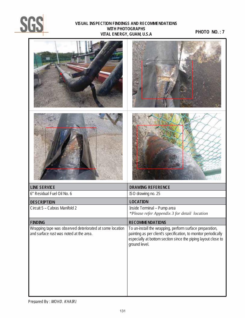
6’’ Residual Fuel Oil No. 6
Inside Terminal – Pump area*Please refer Appendix 3 for detail location
Wrapping tape was observed deteriorated at some locationand surface rust was noted at the area.
To un-install the wrapping, perform surface preparation, painting as per client’s specification, to monitor periodicallyespecially at bottom section since the piping layout close toground level.
LINE SERVICE DRAWING REFERENCE
DESCRIPTION LOCATION
ISO drawing no. 25
Circuit 5 – Cabras Manifold 2
VISUAL INSPECTION FINDINGS AND RECOMMENDATIONSWITH PHOTOGRAPHS
VITAL ENERGY, GUAM, U.S.A PHOTO NO. : 7
131

Prepared By : MOHD. KHAIRI
RECOMMENDATIONSFINDING
6’’ Residual Fuel Oil No. 6
Inside Terminal – Outside pump area*Please refer Appendix 3 for detail location
1. No sign of corrosion at soil to air interface area.2. Corrosion under wrapping with maximum pit depth below than 1mm was noted due to wrap failure and gives a path towater ingress inside.
1. Nil.2. To perform surface preparation and follow by maintenance painting as per client’s specification.
LINE SERVICE DRAWING REFERENCE
DESCRIPTION LOCATION
ISO drawing no. 26
Circuit 5 – Cabras Manifold 2
VISUAL INSPECTION FINDINGS AND RECOMMENDATIONSWITH PHOTOGRAPHS
VITAL ENERGY, GUAM, U.S.A PHOTO NO. : 8
Between support 3 & 4
132

Prepared By : MOHD. KHAIRI
RECOMMENDATIONSFINDING
6’’ Residual Fuel Oil No. 6
Inside Terminal – Outside pump area*Please refer Appendix 3 for detail location
1. Localized corrosion/pits with maximum pit depth below than 1mm was noted at bottom section of piping.2. Corrosion under wrapping with maximum pit depth belowthan 1mm was noted due to wrap failure and gives a path to water ingress inside.
To perform surface preparation and follow by maintenance painting as per client’s specification.
LINE SERVICE DRAWING REFERENCE
DESCRIPTION LOCATION
ISO drawing no. 26
Circuit 5 – Cabras Manifold 2
VISUAL INSPECTION FINDINGS AND RECOMMENDATIONSWITH PHOTOGRAPHS
VITAL ENERGY, GUAM, U.S.A PHOTO NO. : 9
Between support 5 & 6
At support 6
133

Prepared By : MOHD. KHAIRI
RECOMMENDATIONSFINDING
6’’ Residual Fuel Oil No. 6
Inside Terminal – Outside pump area*Please refer Appendix 3 for detail location
Paint failure with surface rust was noted all along of piping. To perform surface preparation and follow by maintenance painting as per client’s specification.
LINE SERVICE DRAWING REFERENCE
DESCRIPTION LOCATION
ISO drawing no. 26
Circuit 5 – Cabras Manifold 2
VISUAL INSPECTION FINDINGS AND RECOMMENDATIONSWITH PHOTOGRAPHS
VITAL ENERGY, GUAM, U.S.A PHOTO NO. : 10
From support 7 to fencing
134

Prepared By : MOHD. KHAIRI
RECOMMENDATIONSFINDING
5’’ & 4’’ Residual Fuel Oil No. 6
Inside Terminal – Pump area*Please refer Appendix 3 for detail location
1. Stud bolt of flange was noted not extend out from the nut.2. Blistering was noted at bottom section of piping.
1. To replace with longer stud bolts with the same materialspecification.
2. To perform surface preparation and follows by maintenance painting as per client’s specification.
LINE SERVICE DRAWING REFERENCE
DESCRIPTION LOCATION
ISO drawing no. 24
Circuit 5 – Cabras Manifold 1
VISUAL INSPECTION FINDINGS AND RECOMMENDATIONSWITH PHOTOGRAPHS
VITAL ENERGY, GUAM, U.S.A PHOTO NO. : 11
Cabras pump no. 2 discharge
135

Prepared By : MOHD. KHAIRI
RECOMMENDATIONSFINDING
4’’ Residual Fuel Oil No. 6
Inside Terminal – Pump area*Please refer Appendix 3 for detail location
1. Piping was noted in contact with flange.2. Paint failure with surface rust was noted at bottom sectionof piping.
1. To use protective material to prevent abrasion at thecontacting area or to re-align the pipeline.2. To perform surface preparation and follows by maintenance painting as per client’s specification.
LINE SERVICE DRAWING REFERENCE
DESCRIPTION LOCATION
ISO drawing no. 24
Circuit 5 – Cabras Manifold 1
VISUAL INSPECTION FINDINGS AND RECOMMENDATIONSWITH PHOTOGRAPHS
VITAL ENERGY, GUAM, U.S.A PHOTO NO. : 12
Cabras pump no. 1 discharge
136

Prepared By : MOHD. KHAIRI
RECOMMENDATIONSFINDING
10’’ Residual Fuel Oil No. 6
Inside Terminal – Pump area*Please refer Appendix 3 for detail location
1. Small bore piping (gauge line) was noted without gusset plates.2. Pipe support modification was noted at support 5 and 6 and surface rust was noted at the area.
1. To replace with longer stud bolts with the same materialspecification.
2. To install 2 gusset plates on the piping to strengthen thepressure line.
LINE SERVICE DRAWING REFERENCE
DESCRIPTION LOCATION
ISO drawing no. 24
Circuit 5 – Cabras Manifold 1
VISUAL INSPECTION FINDINGS AND RECOMMENDATIONSWITH PHOTOGRAPHS
VITAL ENERGY, GUAM, U.S.A PHOTO NO. : 13
Cabras pump no. 1 & 2 discharge
137

Prepared By : MOHD. KHAIRI
RECOMMENDATIONSFINDING
4’’ & 6’’ Residual Fuel Oil No. 6
Inside Terminal – Pump area*Please refer Appendix 3 for detail location
1. Wrapping tape was noted deteriorated at some locationsand paint failure with surface rust was noted at the area.
2. Paint failure with surface was noted at soil to air interfaceArea.
1. To un-install the wrapping tape and perform surface preparation follows by maintenance painting as per client’s specification.2. To perform surface preparation and follows by maintenance painting as per client’s specification.
LINE SERVICE DRAWING REFERENCE
DESCRIPTION LOCATION
ISO drawing no. 25
Circuit 5 – Cabras Manifold 1
VISUAL INSPECTION FINDINGS AND RECOMMENDATIONSWITH PHOTOGRAPHS
VITAL ENERGY, GUAM, U.S.A PHOTO NO. : 14
Cabras pump no. 1 & 2 discharge
138

Prepared By : MOHD. KHAIRI
RECOMMENDATIONSFINDING
6’’ Residual Fuel Oil No. 6
Inside Terminal – Outside pump area*Please refer Appendix 3 for detail location
1. No sign of corrosion at soil to air interface area.2. General corrosion with maximum pit depth below than1mm was noted all along of piping.
1. Nil.2. To perform surface preparation and follows by maintenance painting as per client’s specification.
LINE SERVICE DRAWING REFERENCE
DESCRIPTION LOCATION
ISO drawing no. 26
Circuit 5 – Cabras Manifold 1
VISUAL INSPECTION FINDINGS AND RECOMMENDATIONSWITH PHOTOGRAPHS
VITAL ENERGY, GUAM, U.S.A PHOTO NO. : 15
139

Prepared By : MOHD. KHAIRI
RECOMMENDATIONSFINDING
6’’ Residual Fuel Oil No. 6
Inside Terminal – Outside pump area*Please refer Appendix 3 for detail location
General corrosion with maximum pit depth below than1mm was noted all along of piping.
To perform surface preparation and follows by maintenance painting as per client’s specification.
LINE SERVICE DRAWING REFERENCE
DESCRIPTION LOCATION
ISO drawing no. 26
Circuit 5 – Cabras Manifold 1
VISUAL INSPECTION FINDINGS AND RECOMMENDATIONSWITH PHOTOGRAPHS
VITAL ENERGY, GUAM, U.S.A PHOTO NO. : 16
140

Prepared By : MOHD. KHAIRI
RECOMMENDATIONSFINDING
6’’ Residual Fuel Oil No. 6
Inside Terminal – Outside pump area*Please refer Appendix 3 for detail location
Corrosion under wrapping with maximum pit depth belowthan 1mm due to wrap failure and gives a path to water ingress inside.
To un-install the wrapping tape and perform surface preparation follows by maintenance painting as per client’s specification.
LINE SERVICE DRAWING REFERENCE
DESCRIPTION LOCATION
ISO drawing no. 26
Circuit 5 – Cabras Manifold 1
VISUAL INSPECTION FINDINGS AND RECOMMENDATIONSWITH PHOTOGRAPHS
VITAL ENERGY, GUAM, U.S.A PHOTO NO. : 17
141

Prepared By : MOHD. KHAIRI
RECOMMENDATIONSFINDING
6’’ Residual Fuel Oil No. 6
Inside Terminal – Outside pump area*Please refer Appendix 3 for detail location
General corrosion with maximum pit depth below than1mm was noted all along of piping.
To perform surface preparation and follows by maintenance painting as per client’s specification.
LINE SERVICE DRAWING REFERENCE
DESCRIPTION LOCATION
ISO drawing no. 26
Circuit 5 – Cabras Manifold 1
VISUAL INSPECTION FINDINGS AND RECOMMENDATIONSWITH PHOTOGRAPHS
VITAL ENERGY, GUAM, U.S.A PHOTO NO. : 18
142

APPENDIX 3 - PIPELINE ISOMETRIC DRAWING -
(Support numbering for visual report reference location & corrosion location)
156

157

158

159

160

161

162

163

164

165

166

167

168

169

170

171

172

173

174

175

176

177

178

179

180
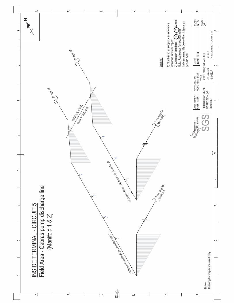
181

182