Embed Size (px)
Citation preview
195
Locating Components
Adjustable Jack Screws ............................................... 212Adjustable Locating Buttons ..................................... 212Alloy Steel Pull Dowel Pins .................................198–199Bullet Nose Dowels ...................................................... 219Bullet Nose Pins ............................................................ 220Drift Handles ................................................................. 213Fixture Jacks .................................................................. 212Fixture Keys, Sine .................................................214–215Fixture Keys, Standard ................................................ 213Flat Feet .......................................................................... 210Jig Feet ...........................................................................209Jig Legs ........................................................................... 210Jig Pins ............................................................................ 203Lanyards ......................................................................... 203Locating Pins .........................................................216–217Locating Pin Liners ....................................................... 218Locating Pin Lock Screws ............................................ 218L-Pins............................................................................... 202Pilot Locating Pins ........................................................ 219Precision Expanding Dowels ...................................... 201Pull Dowel Pins, Alloy Steel ................................198–199Pull Dowels ....................................................................200Rest Buttons ......................................................... 205–207Rest Buttons, Carbide Insert ...................................... 207Rest Buttons, Threaded ...............................................206Rest Pads ........................................................................208Screws, Adjustable Jack .............................................. 212Slotted Locator Bushings ............................................204Stripper Bolts, Kwik-Strip ....................................196–197Tooling/Inspection Balls .....................................221–223T-Pins............................................................................... 202Work Support Jacks, Manual .......................................211
LOCATING COMPONENTS
LO
CA
TIN
G C
OM
PO
NE
NT
S
Step 1 Step 2 Step 3
Step 4
Jergens, Inc. | 15700 S. Waterloo Road | Cleveland, Ohio 44110-3898 USA196
WORKHOLDING SOLUTIONS GROUP
LOCATING COMPONENTS
LO
CA
TIN
G C
OM
PO
NE
NT
S
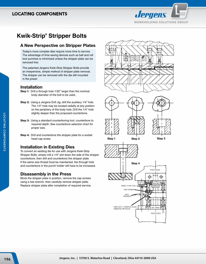
A New Perspective on Stripper PlatesToday's more complex dies require more time to service. The advantage of time saving devices such as ball and roll lock punches is minimized unless the stripper plate can be removed first.
The patented Jergens Kwik-Strip Stripper Bolts provide an inexpensive, simple method of stripper plate removal. The stripper can be removed with the die still mounted in the press!
InstallationStep 1: Drill a through hole 1/32" larger than the nominal
body diameter of the bolt to be used.
Step 2: Using a Jergens Drill Jig, drill the auxiliary 1/4" hole. The 1/4" hole may be located radially at any position on the periphery of the body hole. Drill the 1/4" hole slightly deeper than the proposed counterbore.
Step 3: Using a standard counterboring tool, counterbore to required depth. See counterbore selection chart for proper size.
Step 4: Drill and counterbore the stripper plate for a socket head cap screw.
Installation in Existing DiesTo convert an existing die for use with Jergens Kwik-Strip Stripper Bolts, simply mill a 1/4" slot down the side of the stripper counterbore, then drill and counterbore the stripper plate. If the same size thread must be maintained, the through hole and counterbore in the punch holder will have to be increased.
Disassembly in the PressBlock the stripper plate in position, remove the cap screws using a hex wrench, then carefully remove stripper plate. Replace stripper plate after completion of required service.
Kwik-Strip® Stripper Bolts
197Phone: 877-426-2504 | Fax: +1 216-481-6193 | E-mail: [email protected] | www.jergensinc.com
WORKHOLDING SOLUTIONS GROUP
LOCATING COMPONENTS
LO
CA
TIN
G C
OM
PO
NE
NT
S
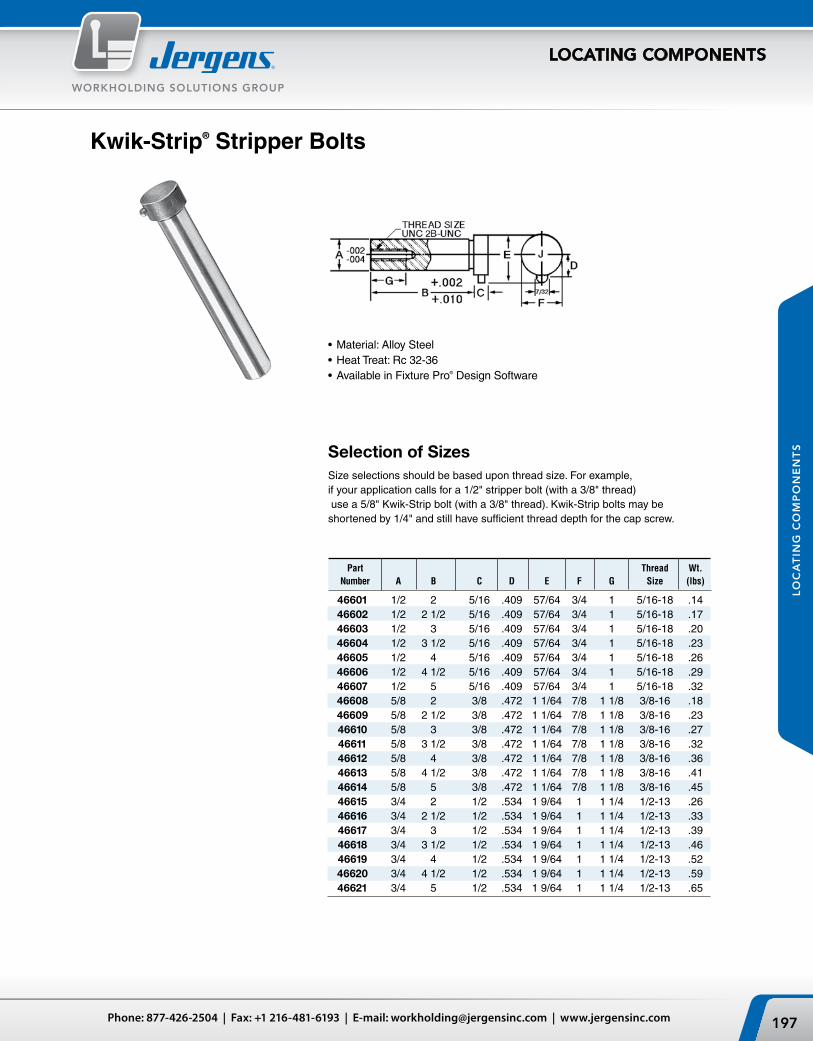
Kwik-Strip® Stripper Bolts
•Material: Alloy Steel•Heat Treat: Rc 32-36•Available in Fixture Pro® Design Software
Selection of SizesSize selections should be based upon thread size. For example, if your application calls for a 1/2" stripper bolt (with a 3/8" thread) use a 5/8" Kwik-Strip bolt (with a 3/8" thread). Kwik-Strip bolts may be shortened by 1/4" and still have sufficient thread depth for the cap screw.
Part Thread Wt. Number A B C D E F G Size (lbs)
46601 1/2 2 5/16 .409 57/64 3/4 1 5/16-18 .14 46602 1/2 2 1/2 5/16 .409 57/64 3/4 1 5/16-18 .17 46603 1/2 3 5/16 .409 57/64 3/4 1 5/16-18 .20 46604 1/2 3 1/2 5/16 .409 57/64 3/4 1 5/16-18 .23 46605 1/2 4 5/16 .409 57/64 3/4 1 5/16-18 .26 46606 1/2 4 1/2 5/16 .409 57/64 3/4 1 5/16-18 .29 46607 1/2 5 5/16 .409 57/64 3/4 1 5/16-18 .32 46608 5/8 2 3/8 .472 1 1/64 7/8 1 1/8 3/8-16 .18 46609 5/8 2 1/2 3/8 .472 1 1/64 7/8 1 1/8 3/8-16 .23 46610 5/8 3 3/8 .472 1 1/64 7/8 1 1/8 3/8-16 .27 46611 5/8 3 1/2 3/8 .472 1 1/64 7/8 1 1/8 3/8-16 .32 46612 5/8 4 3/8 .472 1 1/64 7/8 1 1/8 3/8-16 .36 46613 5/8 4 1/2 3/8 .472 1 1/64 7/8 1 1/8 3/8-16 .41 46614 5/8 5 3/8 .472 1 1/64 7/8 1 1/8 3/8-16 .45 46615 3/4 2 1/2 .534 1 9/64 1 1 1/4 1/2-13 .26 46616 3/4 2 1/2 1/2 .534 1 9/64 1 1 1/4 1/2-13 .33 46617 3/4 3 1/2 .534 1 9/64 1 1 1/4 1/2-13 .39 46618 3/4 3 1/2 1/2 .534 1 9/64 1 1 1/4 1/2-13 .46 46619 3/4 4 1/2 .534 1 9/64 1 1 1/4 1/2-13 .52 46620 3/4 4 1/2 1/2 .534 1 9/64 1 1 1/4 1/2-13 .59 46621 3/4 5 1/2 .534 1 9/64 1 1 1/4 1/2-13 .65

±
±
±
±
±
±
±
±
±
Jergens, Inc. | 15700 S. Waterloo Road | Cleveland, Ohio 44110-3898 USA198
WORKHOLDING SOLUTIONS GROUP
LOCATING COMPONENTS
LO
CA
TIN
G C
OM
PO
NE
NT
S
Alloy Steel Pull Dowel Pins
Spiral Groove (Grooves Help to Relieve Trapped Air)
Flat Vent (Ground Flat Helps to Relieve Trapped Air)
Standard Round (Non-Vented)
Features, Applications & Benefits• Internallythreadedholeallows
removal of pull dowels with a standard screw.
•StandardRoundPullDowelsare typically used in applications featuring a through hole.
•SpiralGroovePull Dowels feature a groove cut to allow trapped air to be released.
•FlatVentPullDowelsfeatureaground flat on one side to release trapped air.
•SpiralGrooveandFlatVentPullDowels are typically used in blind hole applications.
•AllofJergensPrecisionGroundPull Dowels are constructed of heat treated alloy steel.
Jergens Offers 3 Styles of Precision Ground Pull Dowels

199Phone: 877-426-2504 | Fax: +1 216-481-6193 | E-mail: [email protected] | www.jergensinc.com
WORKHOLDING SOLUTIONS GROUP
LOCATING COMPONENTS
LO
CA
TIN
G C
OM
PO
NE
NT
S
Spiral Groove
Precision Ground Pull DowelsTechnical DataMaterial: Alloy Steel
Length Tolerance: ± .010"
Core Hardness: 47 - 58 Rockwell C
Diameter Tolerance: ± .0001"
Surface Hardness: 60 - 64 Rockwell C
Recommended Hole Size: .0005" under Nom. Dia.
Surface Finish: 8 Micro-Inch
Specification: ASME B18.8.2
Flat Vent
Standard Round
Spiral Groove Flat Vent Standard Round Nominal Actual Length Internal Thread
31800 31400 31600 1/4 .2502 1/2 8 - 32 31801 31401 31601 1/4 .2502 3/4 8 - 32 31802 31402 31602 1/4 .2502 1 8 - 32 31803 31403 31603 1/4 .2502 1-1/4 8 - 32 31804 31404 31604 1/4 .2502 1-1/2 8 - 32 31805 31405 31605 1/4 .2502 1-3/4 8 - 32 31806 31406 31606 1/4 .2502 2 8 - 32 31807 31407 31654 1/4 .2502 2-1/4 8 - 32 31808 31408 31607 1/4 .2502 2-1/2 8 - 32 31809 31409 31608 5/16 .3127 3/4 10 - 32 31810 31410 31609 5/16 .3127 1 10 - 32 31811 31411 31610 5/16 .3127 1-1/4 10 - 32 31812 31412 31611 5/16 .3127 1-1/2 10 - 32 31813 31413 31612 5/16 .3127 2 10 - 32 31814 31414 31613 5/16 .3127 2-1/4 10 - 32 31815 31415 31614 5/16 .3127 2-1/2 10 - 32 31816 31416 31615 3/8 .3752 3/4 10 - 32 31817 31417 31616 3/8 .3752 1 10 - 32 31818 31418 31617 3/8 .3752 1-1/4 10 - 32 31819 31419 31618 3/8 .3752 1-1/2 10 - 32 31820 31420 31619 3/8 .3752 1-3/4 10 - 32 31821 31421 31620 3/8 .3752 2 10 - 32 31822 31422 31621 3/8 .3752 2-1/4 10 - 32 31823 31423 31622 3/8 .3752 2-1/2 10 - 32 31824 31424 31623 3/8 .3752 3 10 - 32 31825 31425 31624 7/16 .4377 1 1/4 - 20 31826 31426 31625 7/16 .4377 1-1/2 1/4 - 20 31827 31427 31626 7/16 .4377 2 1/4 - 20 31828 31428 31627 1/2 .5002 3/4 1/4 - 20 31829 31429 31628 1/2 .5002 1 1/4 - 20 31830 31430 31629 1/2 .5002 1-1/4 1/4 - 20 31831 31431 31630 1/2 .5002 1-1/2 1/4 - 20 31832 31432 31631 1/2 .5002 1-3/4 1/4 - 20 31833 31433 31632 1/2 .5002 2 1/4 - 20 31834 31434 31633 1/2 .5002 2-1/4 1/4 - 20 31835 31435 31634 1/2 .5002 2-1/2 1/4 - 20 31836 31436 31635 1/2 .5002 3 1/4 - 20 31837 31437 31636 1/2 .5002 3-1/2 1/4 - 20 31838 31438 31637 1/2 .5002 4 1/4 - 20 31839 31439 31638 5/8 .6252 1-1/4 1/4 - 20 31840 31440 31639 5/8 .6252 1-1/2 1/4 - 20 31841 31441 31640 5/8 .6252 2 1/4 - 20 31842 31442 31641 5/8 .6252 2-1/4 1/4 - 20 31843 31443 31642 5/8 .6252 2-1/2 1/4 - 20 31844 31444 31643 5/8 .6252 3 1/4 - 20 31845 31445 31644 5/8 .6252 4 1/4 - 20 31846 31446 31645 3/4 .7502 1-1/2 5/16 - 18 31847 31456 31655 3/4 .7502 1-3/4 5/16 - 18 31848 31447 31646 3/4 .7502 2 5/16 - 18 31849 31448 31647 3/4 .7502 2-1/2 5/16 - 18 31850 31449 31648 3/4 .7502 3 5/16 - 18 31851 31450 31649 3/4 .7502 4 5/16 - 18 31856* 31451 31656 1 1.0002 1-3/4 5/16 - 18 31852* 31452 31650 1 1.0002 2 5/16 - 18 31853* 31453 31651 1 1.0002 2-1/2 5/16 - 18 31854* 31454 31652 1 1.0002 3 5/16 - 18 31855* 31455 31653 1 1.0002 4 5/16 - 18
*3/8-16 Internal Thread

Jergens, Inc. | 15700 S. Waterloo Road | Cleveland, Ohio 44110-3898 USA200
WORKHOLDING SOLUTIONS GROUP
LOCATING COMPONENTS
LO
CA
TIN
G C
OM
PO
NE
NT
S
Part Number A L T
31751 8 20 M5 x 1.0 31753 8 30 M5 x 1.0 31755 8 40 M5 x 1.0 31759 10 20 M6 x 1.0 31761 10 30 M6 x 1.0 31763 10 40 M6 x 1.0 31765 10 50 M6 x 1.0 31767 10 70 M6 x 1.0 31769 12 20 M6 x 1.0 31771 12 30 M6 x 1.0 31773 12 40 M6 x 1.0
Part Number A L T
31775 12 50 M6 x 1.0 31776 12 60 M6 x 1.0 31777 12 70 M6 x 1.0 31780 16 40 M8 x 1.25 31782 16 50 M8 x 1.25 31783 16 60 M8 x 1.25 31784 16 70 M8 x 1.25 31787 20 50 M10 x 1.6 31788 20 60 M10 x 1.6 31789 20 70 M10 x 1.6
•Material: Low Carbon Steel•Heat Treat: Case Hardened•Available in Fixture Pro® Design Software
Flat ground on the side for air release in blind holes.
Pull DowelsMetric
Button head screw not included.
A
LL1
B
EXPANDING DOWELS1-8-10
A
LL1
B
EXPANDING DOWELS1-8-10
201Phone: 877-426-2504 | Fax: +1 216-481-6193 | E-mail: [email protected] | www.jergensinc.com
WORKHOLDING SOLUTIONS GROUP
LOCATING COMPONENTS
LO
CA
TIN
G C
OM
PO
NE
NT
S
Inch
PartNumber
NominalDiameter
Inch
NominalLength (L)
Inch
RecommendedHole Diameter
Hex Key Sizes
A Diameter B Diameter L1 Bottom Top
+0.001/-0.000" +0.000/-0.001" +0.000/-0.010" ±0.005" Step 1 Step 2
29401 1/4 1/2 0.250 0.249 0.245 0.428 5/64 3/32
29402 3/8 3/4 0.375 0.374 0.370 0.634 1/8 5/32
29403 1/2 1 0.500 0.499 0.495 0.881 5/32 3/16
29404 5/8 1 1/4 0.625 0.624 0.620 1.162 3/16 7/32
29405 3/4 1 1/2 0.750 0.749 0.745 1.390 1/4 5/16
29406 1 2 1.000 0.999 0.995 1.758 3/8 1/2
Metric
Part Number
Nominal Diameter
(mm)
Nominal Length (L)
(mm)
Recommended Hole Diameter
Hex Key Sizes
A Diameter B Diameter L1 Bottom Top
+0.025/-0.00mm +0.00/-0.025mm +0.00/-0.25mm ±0.13mm Step 1 Step 2
29451 10 20 10 9.98 9.88 17.45 3 4
29452 12 25 12 11.98 11.89 22.48 4 5
29453 14 28 14 13.97 13.89 24.74 4 5
29454 16 32 16 15.98 15.90 29.51 5 6
29455 20 38 20 19.98 19.89 35.31 6 8
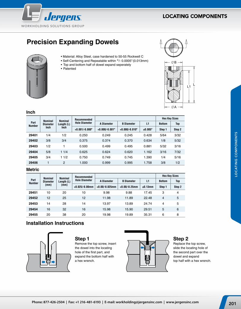
Installation Instructions
Step 1Remove the top screw, insert the dowel into the locating hole of the first part, and expand the bottom half with a hex wrench.
Step 2Replace the top screw, slide the locating hole of the second part over the dowel and expand top half with a hex wrench.
Precision Expanding Dowels
•Material:AlloySteel,casehardenedto50-55RockwellC•Self-CenteringandRepeatablewithin+/- 0.0005" (0.013mm)•Topandbottomhalfofdowelexpandseperately•Patented
Jergens, Inc. | 15700 S. Waterloo Road | Cleveland, Ohio 44110-3898 USA202
WORKHOLDING SOLUTIONS GROUP
LOCATING COMPONENTS
LO
CA
TIN
G C
OM
PO
NE
NT
S
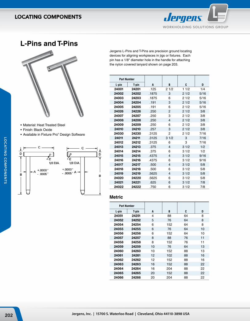
L-Pins and T-Pins
•Material: Heat Treated Steel•Finish: Black Oxide•Available in Fixture Pro® Design Software
Jergens L-Pins and T-Pins are precision ground locating devices for aligning workpieces in jigs or fixtures. Each pin has a 1/8" diameter hole in the handle for attaching the nylon covered lanyard shown on page 203.
Part Number
L-pin T-pin A B C D
24001 24201 .125 2 1/2 1 1/2 1/4 24002 24202 .1875 3 2 1/2 5/16 24003 24203 .1875 6 2 1/2 5/16 24004 24204 .191 3 2 1/2 5/16 24005 24205 .191 6 2 1/2 5/16 24026 24226 .250 2 2 1/2 3/8 24007 24207 .250 3 2 1/2 3/8 24008 24208 .250 4 2 1/2 3/8 24009 24209 .250 6 2 1/2 3/8 24010 24210 .257 3 2 1/2 3/8 24030 24230 .3125 2 2 1/2 7/16 24011 24211 .3125 3 1/2 3 7/16 24012 24212 .3125 6 3 7/16 24013 24213 .375 4 3 1/2 1/2 24014 24214 .375 6 3 1/2 1/2 24015 24215 .4375 4 3 1/2 9/16 24016 24216 .4375 6 3 1/2 9/16 24017 24217 .500 4 3 1/2 5/8 24018 24218 .500 6 3 1/2 5/8 24019 24219 .5625 4 3 1/2 5/8 24020 24220 .5625 6 3 1/2 5/8 24021 24221 .625 6 3 1/2 7/8 24022 24222 .750 6 3 1/2 7/8
Metric
Part Number
L-pin T-pin A B C D 24051 24251 4 88 64 8 24052 24252 5 76 64 8 24054 24254 6 152 64 8 24055 24255 6 76 64 10 24056 24256 6 152 64 10 24057 24257 8 88 76 11 24058 24258 8 152 76 11 24059 24259 10 76 64 13 24060 24260 10 152 88 13 24061 24261 12 102 88 16 24062 24262 12 152 88 16 24063 24263 16 152 88 22 24064 24264 16 204 88 22 24065 24265 20 152 88 22 24066 24266 20 204 88 22

ØA
1/2"
D
C
B
ØE
+.000-.0005 -.0005
+.000
F
D
ØE
1/2"
C
B
ØA
ØA
1/2"
D
C
B
ØE
+.000-.0005 -.0005
+.000
F
D
ØE
1/2"
C
B
ØA
203Phone: 877-426-2504 | Fax: +1 216-481-6193 | E-mail: [email protected] | www.jergensinc.com
WORKHOLDING SOLUTIONS GROUP
LOCATING COMPONENTS
LO
CA
TIN
G C
OM
PO
NE
NT
S
Jig PinsJig Pins are precision ground locating devices. The straight handle style comes with a hole for easy attachment of a lanyard. The T-handle style can be converted to an L-handle style by tapping the roll pin with a hammer.
•Material:LowCarbonSteel•Finish:BlackOxide•HeatTreat:CaseHardenedRc58-62(pinonly)
Part Number A B C D E F
24111 .2500 2 1/2 2 5/8 1/2 1/4 2 24112 .3125 2 1/2 2 5/8 9/16 1/4 3 24113 .3750 4 2 5/8 5/8 1/4 3 24114 .5000 3 2 5/8 3/4 5/16 3
T- Handle Jig Pin
Straight Handle Jig Pin
T-Handle Jig Pins
Straight Handle Jig Pin
Part Number A B C D E
24101 .2500 2 1/2 2 5/8 1/2 1/4 24102 .3125 2 1/2 2 5/8 9/16 1/4 24103 .3750 4 2 5/8 5/8 1/4 24104 .5000 3 2 5/8 3/4 5/16
Lanyards with Tabs
890054* 890104* 890056* 890106* 890058* 890108* 890060* 890110* 890062* 890112* 890066* 890116* 890070* 890120* 890074* 890124*
Ordering Lanyards When Supplied Separately Without Pins
Substitute the asterisk (*) with the proper hole size letter from Table 1.
890204 890254 890304 890404890206 890256 890306 890406890208 890258 890308 890408890210 890260 890310 890410890212 890262 890312 890412890216 890266 890316 890416890220 890270 890320 890420890224 890274 890324 890424
Lanyards without TabsLanyardLoop/Eyelet
Round Tab Oval Tab Stainless
Aluminum
Steel
468
1012162024
102 152 203 254 305 406 508 610
M5 #10
2 Loops 1 Loops (Pin) For Screw SizeLength
inch mm
Table 1 Tab Hole Size
Tab Mounting Hole Diameter Inch mm Size Letter
0.131 3.3 P0.196 4.9 Q0.257 6.5 R0.283† 7.1† S0.320† 8.1† T0.379† 9.6† U0.406† 10.3† V0.468† 11.8† W0.515† 13.1† Y
(†) These sizes only available in stainless steel round tabs
Length inch mm468
1012162024
102 152 203 254 305 406 508 610
•To attach lanyard to L or T Pins order Split Ring 890000•To permanently attach Lanyard to L or T Pins add -C to Lanyard part number•For Lanyard &Tab drawings see Kwik-Lok™ Pins in Specialty Fastener Solutions Catalog or Master Catalog
Lanyards
A/2
C/2
A
D
Roll Pin
B Dia
C Dia +.0004+.0001
ConcentricGround Lead
16-PitchDiamond
Knurl
A Dimension CenteredWithin ±.0001 of C Dia.
A
D
B Dia
C Dia Over Knurl
+.001-.001
A/2
C/2
A
D
Roll Pin
B Dia
C Dia +.0004+.0001
ConcentricGround Lead
16-PitchDiamond
Knurl
A Dimension CenteredWithin ±.0001 of C Dia.
A
D
B Dia
C Dia Over Knurl
+.001-.001
Jergens, Inc. | 15700 S. Waterloo Road | Cleveland, Ohio 44110-3898 USA204
WORKHOLDING SOLUTIONS GROUP
LOCATING COMPONENTS
LO
CA
TIN
G C
OM
PO
NE
NT
S
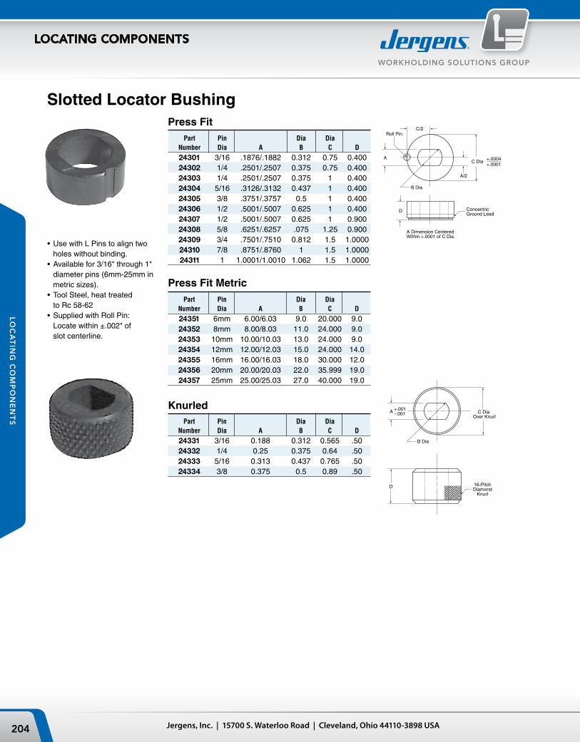
Slotted Locator Bushing
•UsewithLPinstoaligntwo holes without binding.
•Availablefor3/16"through1" diameter pins (6mm-25mm in metric sizes).
•ToolSteel,heattreated to Rc 58-62
•SuppliedwithRollPin: Locate within ±.002" of slot centerline.
Knurled Part Pin Dia Dia Number Dia A B C D
24331 3/16 0.188 0.312 0.565 .50 24332 1/4 0.25 0.375 0.64 .50 24333 5/16 0.313 0.437 0.765 .50 24334 3/8 0.375 0.5 0.89 .50
Press Fit Metric Part Pin Dia Dia Number Dia A B C D
24351 6mm 6.00/6.03 9.0 20.000 9.0 24352 8mm 8.00/8.03 11.0 24.000 9.0 24353 10mm 10.00/10.03 13.0 24.000 9.0 24354 12mm 12.00/12.03 15.0 24.000 14.0 24355 16mm 16.00/16.03 18.0 30.000 12.0 24356 20mm 20.00/20.03 22.0 35.999 19.0 24357 25mm 25.00/25.03 27.0 40.000 19.0
Press Fit Part Pin Dia Dia Number Dia A B C D
24301 3/16 .1876/.1882 0.312 0.75 0.400 24302 1/4 .2501/.2507 0.375 0.75 0.400 24303 1/4 .2501/.2507 0.375 1 0.400 24304 5/16 .3126/.3132 0.437 1 0.400 24305 3/8 .3751/.3757 0.5 1 0.400 24306 1/2 .5001/.5007 0.625 1 0.400 24307 1/2 .5001/.5007 0.625 1 0.900 24308 5/8 .6251/.6257 .075 1.25 0.900 24309 3/4 .7501/.7510 0.812 1.5 1.0000 24310 7/8 .8751/.8760 1 1.5 1.0000 24311 1 1.0001/1.0010 1.062 1.5 1.0000
205Phone: 877-426-2504 | Fax: +1 216-481-6193 | E-mail: [email protected] | www.jergensinc.com
WORKHOLDING SOLUTIONS GROUP
LOCATING COMPONENTS
LO
CA
TIN
G C
OM
PO
NE
NT
S
“B” Ground† “B” Unground† Part Part Number Number A B C D 34751 45771 10 6 12 5 34754 45774 13 6 18 6 34757 45777 16 6 18 10 34758 45778 16 10 22 10 34759 45780 16 12 25 10 34763 45786 22 16 31 12 34766 45790 25 12 30 16
†“B” Dimension for ground style is +.013/-.000mm, ungrounded style is +.25/+.38mm.
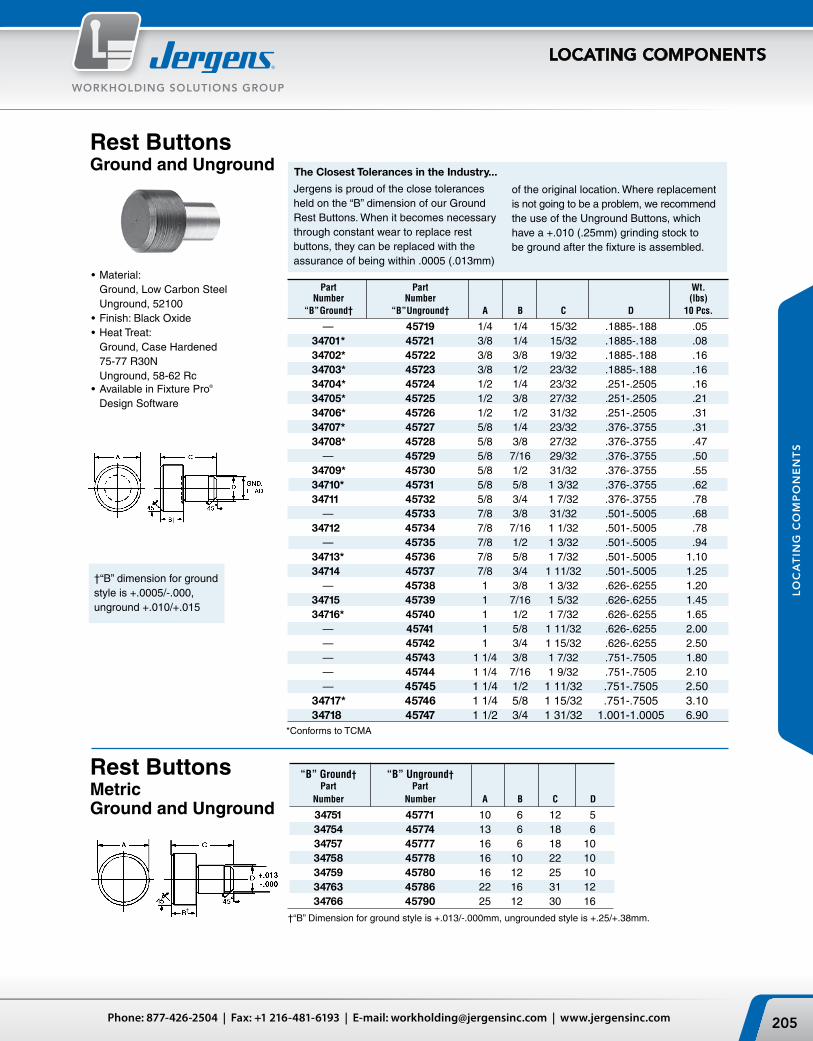
Part Part Wt. Number Number (lbs) “B” Ground† “B” Unground† A B C D 10 Pcs.
— 45719 1/4 1/4 15/32 .1885-.188 .05 34701* 45721 3/8 1/4 15/32 .1885-.188 .08 34702* 45722 3/8 3/8 19/32 .1885-.188 .16 34703* 45723 3/8 1/2 23/32 .1885-.188 .16 34704* 45724 1/2 1/4 23/32 .251-.2505 .16 34705* 45725 1/2 3/8 27/32 .251-.2505 .21 34706* 45726 1/2 1/2 31/32 .251-.2505 .31 34707* 45727 5/8 1/4 23/32 .376-.3755 .31 34708* 45728 5/8 3/8 27/32 .376-.3755 .47 — 45729 5/8 7/16 29/32 .376-.3755 .50 34709* 45730 5/8 1/2 31/32 .376-.3755 .55 34710* 45731 5/8 5/8 1 3/32 .376-.3755 .62 34711 45732 5/8 3/4 1 7/32 .376-.3755 .78 — 45733 7/8 3/8 31/32 .501-.5005 .68 34712 45734 7/8 7/16 1 1/32 .501-.5005 .78 — 45735 7/8 1/2 1 3/32 .501-.5005 .94 34713* 45736 7/8 5/8 1 7/32 .501-.5005 1.10 34714 45737 7/8 3/4 1 11/32 .501-.5005 1.25 — 45738 1 3/8 1 3/32 .626-.6255 1.20 34715 45739 1 7/16 1 5/32 .626-.6255 1.45 34716* 45740 1 1/2 1 7/32 .626-.6255 1.65 — 45741 1 5/8 1 11/32 .626-.6255 2.00 — 45742 1 3/4 1 15/32 .626-.6255 2.50 — 45743 1 1/4 3/8 1 7/32 .751-.7505 1.80 — 45744 1 1/4 7/16 1 9/32 .751-.7505 2.10 — 45745 1 1/4 1/2 1 11/32 .751-.7505 2.50 34717* 45746 1 1/4 5/8 1 15/32 .751-.7505 3.10 34718 45747 1 1/2 3/4 1 31/32 1.001-1.0005 6.90
Rest ButtonsGround and Unground
Jergens is proud of the close tolerances heldonthe“B”dimensionofourGroundRest Buttons. When it becomes necessary through constant wear to replace rest buttons, they can be replaced with the assurance of being within .0005 (.013mm)
•Material: Ground,LowCarbonSteel Unground, 52100•Finish:BlackOxide•HeatTreat: Ground,CaseHardened 75-77 R30N Unground, 58-62 Rc•AvailableinFixturePro®
Design Software
†“B” dimension for ground style is +.0005/-.000, unground +.010/+.015
Rest ButtonsMetric Ground and Unground
*Conforms to TCMA
of the original location. Where replacement is not going to be a problem, we recommend the use of the Unground Buttons, which have a +.010 (.25mm) grinding stock to be ground after the fixture is assembled.
The Closest Tolerances in the Industry...
Jergens, Inc. | 15700 S. Waterloo Road | Cleveland, Ohio 44110-3898 USA206
WORKHOLDING SOLUTIONS GROUP
LOCATING COMPONENTS
LO
CA
TIN
G C
OM
PO
NE
NT
S Across Part Dia. Flats Number A B C†
D
E
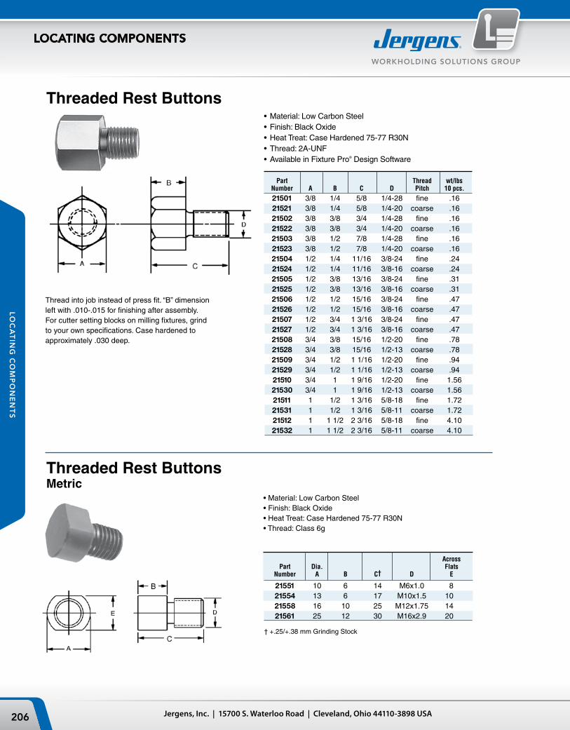
21551 10 6 14 M6x1.0 8 21554 13 6 17 M10x1.5 10 21558 16 10 25 M12x1.75 14 21561 25 12 30 M16x2.9 20
†+.25/+.38mmGrindingStock
Threaded Rest Buttons
Thread into job instead of press fit. “B” dimensionleft with .010-.015 for finishing after assembly. For cutter setting blocks on milling fixtures, grind to your own specifications. Case hardened to approximately .030 deep.
•Material: Low Carbon Steel•Finish: Black Oxide•Heat Treat: Case Hardened 75-77 R30N•Thread: 2A-UNF•Available in Fixture Pro® Design Software
Threaded Rest ButtonsMetric
•Material:LowCarbonSteel•Finish:BlackOxide•HeatTreat:CaseHardened75-77R30N•Thread:Class6g
Part Thread wt/lbs Number A B C D Pitch 10 pcs.
21501 3/8 1/4 5/8 1/4-28 fine .16 21521 3/8 1/4 5/8 1/4-20 coarse .16 21502 3/8 3/8 3/4 1/4-28 fine .16 21522 3/8 3/8 3/4 1/4-20 coarse .16 21503 3/8 1/2 7/8 1/4-28 fine .16 21523 3/8 1/2 7/8 1/4-20 coarse .16 21504 1/2 1/4 11/16 3/8-24 fine .24 21524 1/2 1/4 11/16 3/8-16 coarse .24 21505 1/2 3/8 13/16 3/8-24 fine .31 21525 1/2 3/8 13/16 3/8-16 coarse .31 21506 1/2 1/2 15/16 3/8-24 fine .47 21526 1/2 1/2 15/16 3/8-16 coarse .47 21507 1/2 3/4 1 3/16 3/8-24 fine .47 21527 1/2 3/4 1 3/16 3/8-16 coarse .47 21508 3/4 3/8 15/16 1/2-20 fine .78 21528 3/4 3/8 15/16 1/2-13 coarse .78 21509 3/4 1/2 1 1/16 1/2-20 fine .94 21529 3/4 1/2 1 1/16 1/2-13 coarse .94 21510 3/4 1 1 9/16 1/2-20 fine 1.56 21530 3/4 1 1 9/16 1/2-13 coarse 1.56 21511 1 1/2 1 3/16 5/8-18 fine 1.72 21531 1 1/2 1 3/16 5/8-11 coarse 1.72 21512 1 1 1/2 2 3/16 5/8-18 fine 4.10 21532 1 1 1/2 2 3/16 5/8-11 coarse 4.10
207Phone: 877-426-2504 | Fax: +1 216-481-6193 | E-mail: [email protected] | www.jergensinc.com
WORKHOLDING SOLUTIONS GROUP
LOCATING COMPONENTS
LO
CA
TIN
G C
OM
PO
NE
NT
S
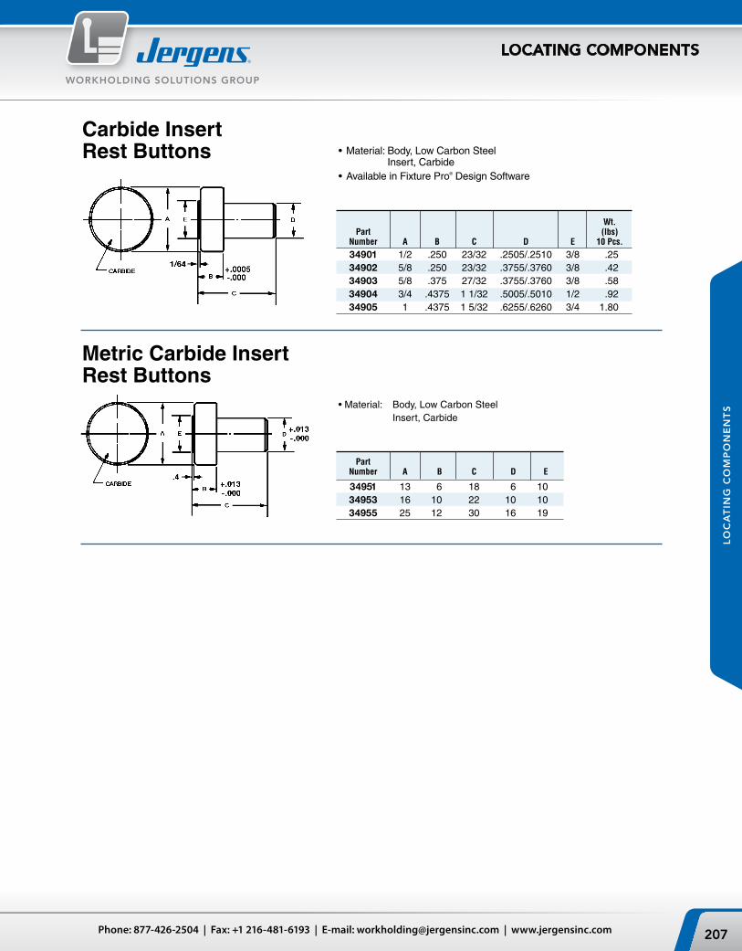
•Material: Body, Low Carbon Steel Insert, Carbide
•Available in Fixture Pro® Design Software
Carbide Insert Rest Buttons
Part Number A B C D E
34951 13 6 18 6 10 34953 16 10 22 10 10 34955 25 12 30 16 19
Metric Carbide Insert Rest Buttons
•Material: Body,LowCarbonSteel Insert, Carbide
Wt. Part (lbs) Number A B C D E 10 Pcs.
34901 1/2 .250 23/32 .2505/.2510 3/8 .25 34902 5/8 .250 23/32 .3755/.3760 3/8 .42 34903 5/8 .375 27/32 .3755/.3760 3/8 .58 34904 3/4 .4375 1 1/32 .5005/.5010 1/2 .92 34905 1 .4375 1 5/32 .6255/.6260 3/4 1.80
Jergens, Inc. | 15700 S. Waterloo Road | Cleveland, Ohio 44110-3898 USA208
WORKHOLDING SOLUTIONS GROUP
LOCATING COMPONENTS
LO
CA
TIN
G C
OM
PO
NE
NT
S
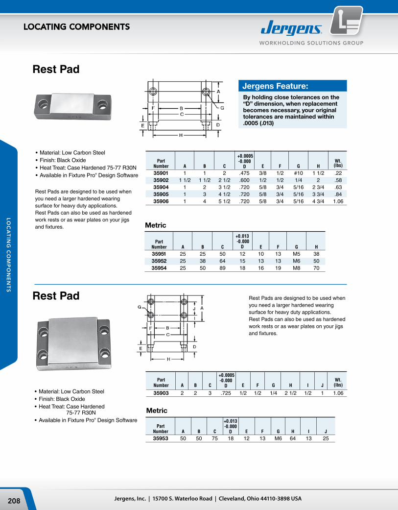
Part Number A B C E F G H
35951 25 25 50 12 10 13 M5 38 35952 25 38 64 15 13 13 M6 50 35954 25 50 89 18 16 19 M8 70
Part Wt. Number A B C E F G H I J (lbs)
35903 2 2 3 .725 1/2 1/2 1/4 2 1/2 1/2 1 1.06
Part Wt. Number A B C E F G H (lbs)
35901 1 1 2 .475 3/8 1/2 #10 1 1/2 .22 35902 1 1/2 1 1/2 2 1/2 .600 1/2 1/2 1/4 2 .58 35904 1 2 3 1/2 .720 5/8 3/4 5/16 2 3/4 .63 35905 1 3 4 1/2 .720 5/8 3/4 5/16 3 3/4 .84 35906 1 4 5 1/2 .720 5/8 3/4 5/16 4 3/4 1.06
•Material: Low Carbon Steel•Finish: Black Oxide•Heat Treat: Case Hardened 75-77 R30N•Available in Fixture Pro® Design Software
Rest Pad
Rest Pads are designed to be used when you need a larger hardened wearing surface for heavy duty applications. Rest Pads can also be used as hardened work rests or as wear plates on your jigs and fixtures.
•Material: Low Carbon Steel•Finish: Black Oxide•Heat Treat: Case Hardened
75-77 R30N•Available in Fixture Pro® Design Software
+0.013 -0.000
D
Part Number A B C E F G H I J
35953 50 50 75 18 12 13 M6 64 13 25
+0.013-0.000
D
+0.0005-0.000
D
+0.0005-0.000
D
Metric
Metric
Rest Pad Rest Pads are designed to be used when you need a larger hardened wearing surface for heavy duty applications. Rest Pads can also be used as hardened work rests or as wear plates on your jigs and fixtures.
Jergens Feature:By holding close tolerances on the “D” dimension, when replacement becomes necessary, your original tolerances are maintained within .0005 (.013)
209Phone: 877-426-2504 | Fax: +1 216-481-6193 | E-mail: [email protected] | www.jergensinc.com
WORKHOLDING SOLUTIONS GROUP
LOCATING COMPONENTS
LO
CA
TIN
G C
OM
PO
NE
NT
S
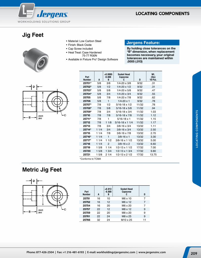
Jig Feet•Material: Low Carbon Steel•Finish: Black Oxide•Cap Screw included•Heat Treat: Case Hardened
75-77 R30N•Available in Fixture Pro® Design Software
Metric Jig Feet
+0.013 Socket Head Part -0.000 Capscrew Number A B C D
25751 16 10 M6 x 10 7 25752 16 12 M6 x 12 7 25754 16 20 M6 x 20 7 25757 22 12 M8 x 12 9 25759 22 20 M8 x 20 9 25761 22 24 M8 x 25 9 25766 32 24 M10 x 25 11
+0.0005 Socket Head Wt. Part -0.000 Capscrew (lbs) Number A B C D 10 Pcs.
25701* 5/8 3/8 1/4-20 x 3/8 9/32 .31 25702* 5/8 1/2 1/4-20 x 1/2 9/32 .31 25703* 5/8 5/8 1/4-20 x 5/8 9/32 .47 25704* 5/8 3/4 1/4-20 x 3/4 9/32 .55 25705 5/8 7/8 1/4-20 x 7/8 9/32 .62 25706 5/8 1 1/4-20 x 1 9/32 .78 25707* 7/8 1/2 5/16-18 x 1/2 11/32 .78 25708* 7/8 5/8 5/16-18 x 5/8 11/32 .94 25709* 7/8 3/4 5/16-18 x 3/4 11/32 1.03 25710 7/8 7/8 5/16-18 x 7/8 11/32 1.12 25711* 7/8 1 5/16-18 x 1 11/32 1.15 25712 7/8 1 1/8 5/16-18 x 1 1/4 11/32 1.17 25713 7/8 3/4 3/8-16 x 3/4 13/32 1.11 25714* 1 1/4 3/4 3/8-16 x 3/4 13/32 2.50 25715 1 1/4 7/8 3/8-16 x 7/8 13/32 2.70 25716* 1 1/4 1 3/8-16 x 1 13/32 3.30 25717* 1 1/4 1 1/2 3/8-16 x 1 1/2 13/32 5.00 25718 1 1/4 2 3/8-16 x 2 13/32 6.60 25719 1 5/8 1 1/4 1/2-13 x 1 1/2 17/32 7.00 25720 1 5/8 1 3/4 1/2-13 x 1 3/4 17/32 9.80 25721 1 5/8 2 1/4 1/2-13 x 2 1/2 17/32 13.75
*Conforms to TCMA
Jergens Feature:By holding close tolerances on the “B” dimension, when replacement becomes necessary, your original tolerances are maintained within .0005 (.013)

Jergens, Inc. | 15700 S. Waterloo Road | Cleveland, Ohio 44110-3898 USA210
WORKHOLDING SOLUTIONS GROUP
LOCATING COMPONENTS
LO
CA
TIN
G C
OM
PO
NE
NT
S
Jig Legs
The Jergens Jig Legs are ideal for cutting costs in simple jig plates. They assure lasting accuracy in your jig plate with a larger bearing surface at the top the the leg. The large diameter rest button provides more bearing surface for spot facing or counterboring on the bottom side. Both legs and rest buttons are hardened for long life.
•Material: Low Carbon Steel•Finish: Black Oxide•Heat Treat: Case Hardened 75-77 R30N•Cap Screw Included•Available in Fixture Pro® Design Software
Part Cap Screw Wt. Number A B C D F (lbs)
25301 1 5/8 1/4-20 5/8 1/4-20 x 1 .13 25302 2 5/8 1/4-20 5/8 1/4-20 x 1 .20 25303 3 5/8 1/4-20 7/8 1/4-20 x 1 .28 25304 4 7/8 3/8-16 7/8 3/8-16 x 1 3/4 .81 25305 5 7/8 3/8-16 7/8 3/8-16 x 1 3/4 1.00 25306 6 7/8 3/8-16 7/8 3/8-16 x 1 3/4 1.10
Flat Head Wt. Part Screw (lbs) Number A C 10 Pcs
19301 1/2 1/8 8-32 x 3/8 .06 19302 1/2 1/4 8-32 x 1/2 .16 19303 5/8 1/4 10-32 x 5/8 .21 19304 7/8 3/8 1/4-20 x 3/4 .62 19305 1 1/4 3/8 5/16-18 x 3/4 1.25 19306 1 5/8 3/8 3/8-16 x 3/4 2.20
•Material: Low Carbon Steel•Heat Treat: Case Hardened 75-77 R30N•Cap Screw Included•Available in Fixture Pro® Design Software
Flat Feet
+0.0005-0.000
B
Metric
Jergens Feature:By holding close tolerances on the “B” dimension, when replacement becomes necessary, your original tolerances are maintained within .0005 (.013mm)
Flat Head Part Screw Wt. (Kg) Number A C 10 Pcs
19351 13 3 M4 x 10 .03 19352 13 6 M4 x 12 .09 19353 16 6 M5 x 16 .11 19354 22 10 M6 x 20 .33 19355 31 10 M8 x 20 .47
+0.013 -0.000
B
211Phone: 877-426-2504 | Fax: +1 216-481-6193 | E-mail: [email protected] | www.jergensinc.com
WORKHOLDING SOLUTIONS GROUP
LOCATING COMPONENTS
LO
CA
TIN
G C
OM
PO
NE
NT
S
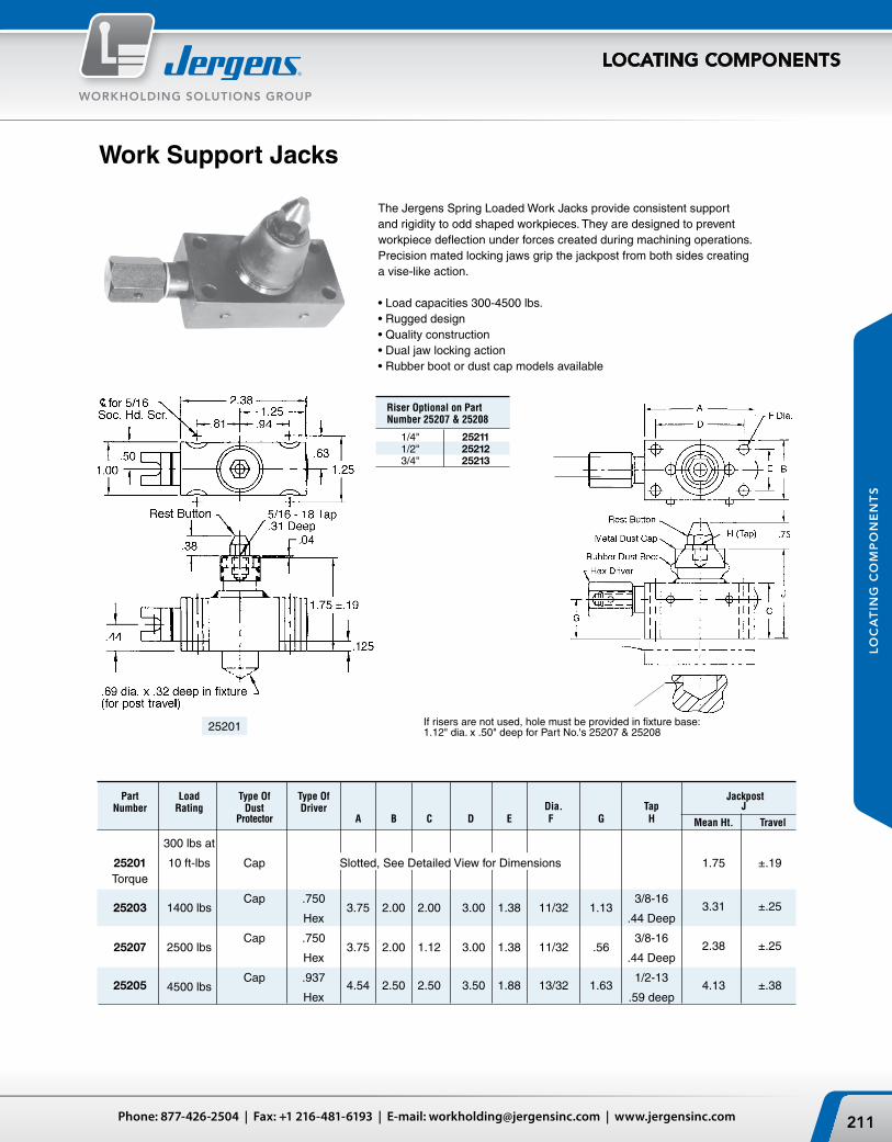
Riser Optional on Part Number 25207 & 25208
1/4" 25211 1/2" 25212 3/4" 25213
If risers are not used, hole must be provided in fixture base: 1.12" dia. x .50" deep for Part No.'s 25207 & 25208
The Jergens Spring Loaded Work Jacks provide consistent support and rigidity to odd shaped workpieces. They are designed to prevent workpiece deflection under forces created during machining operations. Precision mated locking jaws grip the jackpost from both sides creating a vise-like action.
•Loadcapacities300-4500lbs.•Ruggeddesign•Qualityconstruction•Dualjawlockingaction•Rubberbootordustcapmodelsavailable
25201
Work Support Jacks
Part Load Type Of Type Of Jackpost Number Rating Dust Driver Dia. Tap J Protector A B C D E F G H Mean Ht. Travel
300 lbs at
25201 10ft-lbs Cap Slotted,SeeDetailedViewforDimensions 1.75 ±.19 Torque
25203
1400 lbs
Cap .750 3.75 2.00 2.00 3.00 1.38 11/32 1.13
3/8-16 3.31 ±.25
Hex .44 Deep
25207
2500 lbs
Cap .750 3.75 2.00 1.12 3.00 1.38 11/32 .56
3/8-16 2.38 ±.25
Hex .44 Deep
25205
4500 lbs
Cap .937 4.54 2.50 2.50 3.50 1.88 13/32 1.63
1/2-13 4.13 ±.38
Hex .59 deep

BHEX
D
E F
A
ØC
THREAD SIZEG SPHER. RAD.
21403_CAT
Jergens, Inc. | 15700 S. Waterloo Road | Cleveland, Ohio 44110-3898 USA212
WORKHOLDING SOLUTIONS GROUP
LOCATING COMPONENTS
LO
CA
TIN
G C
OM
PO
NE
NT
S
Fixture Jacks
Part Part Press D Number Number Fit Thread Wt. Radius Serrated A B C Min. Max. E F G H Size (lbs)
24901 25101 5/8 1 3/16 3/16 9/16 1 1/2 1 1/4 5/32 3/8 3/8-16 .19 24902 25102 1 1 5/8 3/16 7/8 2 7/16 1 5/16 15/32 7/16 7/16 5/8-11 .55 24903 25103 1 1/2 2 3/4 3/16 7/8 3 1/2 1 3/4 13/16 1/2 9/16 1-8 1.90
Designed as a positive locking jack for irregular clamping to achieve various heights requiring a positive pressure stop. Adjustable to fit height irregularities of milling operations. Available in either a smooth radius head or a hardened tool steel serrated gripping surface. Elevates vertically, no rotation. Outer diameter of bushing ground for press-fit.
•Material: Bushing, Low Carbon Steel Radius Stem, Low Carbon Steel Serrated Stem, 4140
•Finish: Bushing, Black Oxide Radius Stem, Black Oxide Serrated Stem, Black Oxide
•Heat Treat: Bushing, Case Hardened 74-77 R30N Radius Stem, Case Hardened Serrated Stem, Rc 45-48
•Available in Fixture Pro® Design Software
Adjustable Locating Buttons •Material:LowCarbonSteel•Finish:BlackOxide•HeatTreat:CaseHardened87-92R15N
Part Thread Number Size A B C D E F G
21401 10-32 1 1/4 3/16 1/8 1/8 3/4 1/8 21402 1/4-28 1 1/2 3/8 1/4 3/16 3/16 1 1/8 3/16 21403 5/16-24 1 3/4 7/16 5/16 1/4 1/4 1 1/4 3/16 21404 3/8-24 2 1/2 3/8 1/4 1/4 1 1/2 1/4 21405 1/2-20 2 1/2 5/8 1/2 5/16 5/16 1 7/8 5/16 21406 5/8-18 3 3/4 5/8 3/8 3/8 1 1/4 3/8 21407 3/4-16 3 1/2 7/8 3/4 7/16 7/16 2 5/8 7/16
Adjustable Jack Screws
Part Wt. Lock Nut Number A B C (lbs) (Not Included)
25001 3/8-16 1-1/4 1-1/8 0.15 28101 25003 3/8-16 2 1-1/8 0.18 28101 25005 1/2-13 1-5/8 1-1/8 0.20 28102 25007 1/2-13 2-1/2 1-1/8 0.25 28102 25009 5/8-11 2 1-3/8 0.34 28103 25011 5/8-11 3 1-3/8 0.43 28103
•Material:LowCarbonSteel•Finish:BlackOxide•HeatTreat:Screw/StemCaseHardened87-92R15N
213Phone: 877-426-2504 | Fax: +1 216-481-6193 | E-mail: [email protected] | www.jergensinc.com
WORKHOLDING SOLUTIONS GROUP
LOCATING COMPONENTS
LO
CA
TIN
G C
OM
PO
NE
NT
S
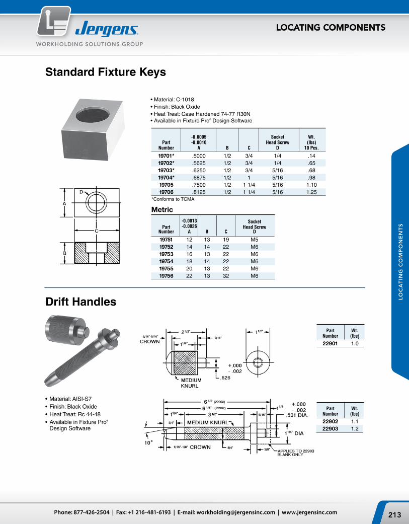
-0.0005 Socket Wt. Part -0.0010 Head Screw (lbs) Number A B C D 10 Pcs.
19701* .5000 1/2 3/4 1/4 .14 19702* .5625 1/2 3/4 1/4 .65 19703* .6250 1/2 3/4 5/16 .68 19704* .6875 1/2 1 5/16 .98 19705 .7500 1/2 1 1/4 5/16 1.10 19706 .8125 1/2 1 1/4 5/16 1.25
Standard Fixture Keys
*Conforms to TCMA
•Material:C-1018•Finish:BlackOxide•HeatTreat:CaseHardened74-77R30N•AvailableinFixturePro® Design Software
-0.0013 Socket Part -0.0026 Head Screw Number A B C D
19751 12 13 19 M5 19752 14 14 22 M6 19753 16 13 22 M6 19754 18 14 22 M6 19755 20 13 22 M6 19756 22 13 32 M6
Metric
Part Wt. Number (lbs)
22902 1.1 22903 1.2
Part Wt. Number (lbs)
22901 1.0
•Material: AISI-S7•Finish: Black Oxide•Heat Treat: Rc 44-48•Available in Fixture Pro®
Design Software
Drift Handles
Jergens, Inc. | 15700 S. Waterloo Road | Cleveland, Ohio 44110-3898 USA214
WORKHOLDING SOLUTIONS GROUP
LOCATING COMPONENTS
LO
CA
TIN
G C
OM
PO
NE
NT
S
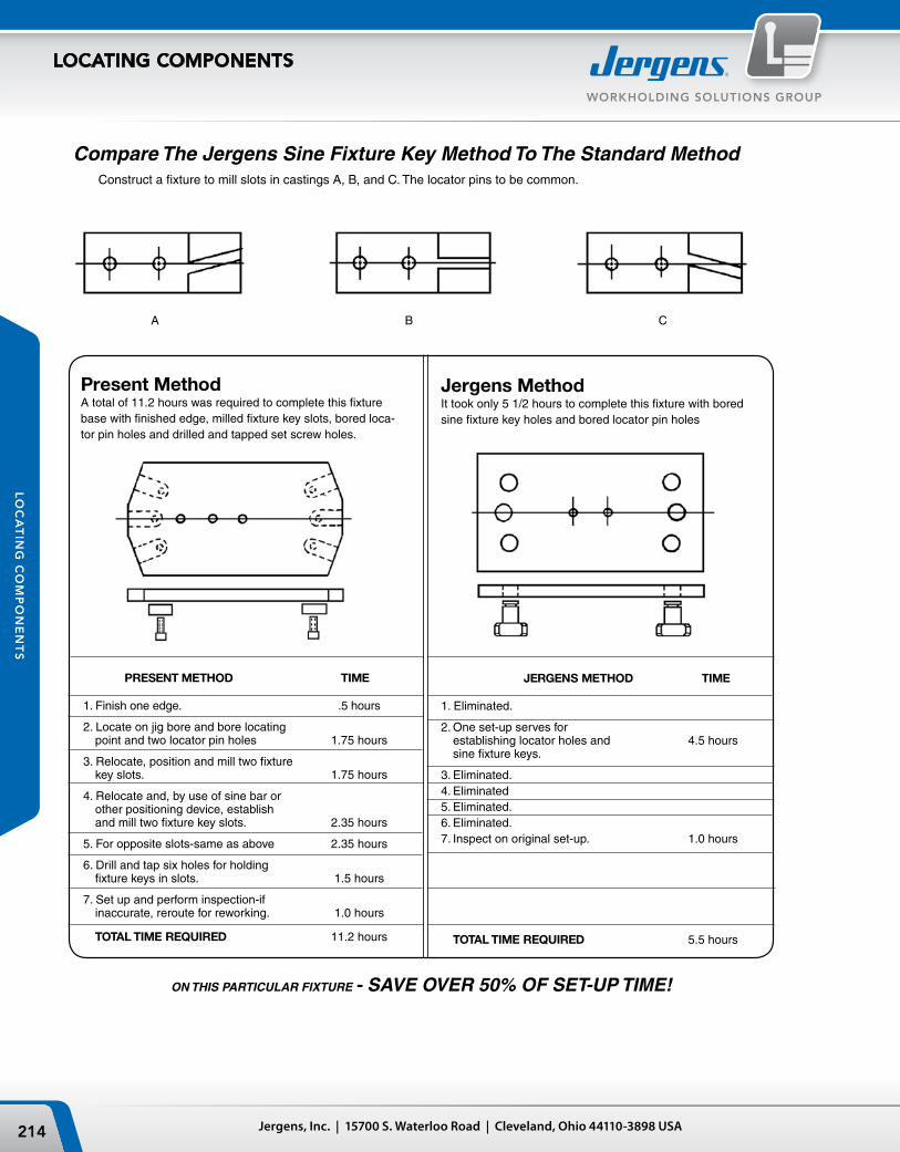
PRESENT METHOD TIME
1. Finish one edge. .5 hours
2. Locate on jig bore and bore locating point and two locator pin holes 1.75 hours
3. Relocate, position and mill two fixture key slots. 1.75 hours
4. Relocate and, by use of sine bar or other positioning device, establish and mill two fixture key slots. 2.35 hours
5. For opposite slots-same as above 2.35 hours
6. Drill and tap six holes for holding fixture keys in slots. 1.5 hours
7. Set up and perform inspection-if inaccurate, reroute for reworking. 1.0 hours
TOTAL TIME REQUIRED 11.2 hours
ON THIS PARTICULAR FIXTURE - SAVE OVER 50% OF SET-UP TIME!
Present MethodA total of 11.2 hours was required to complete this fixture base with finished edge, milled fixture key slots, bored loca-tor pin holes and drilled and tapped set screw holes.
Jergens MethodIt took only 5 1/2 hours to complete this fixture with bored sine fixture key holes and bored locator pin holes
Compare The Jergens Sine Fixture Key Method To The Standard Method Construct a fixture to mill slots in castings A, B, and C. The locator pins to be common.
A B C
JERGENS METHOD TIME
1. Eliminated.
2. One set-up serves for establishing locator holes and 4.5 hours sine fixture keys.
3. Eliminated.4. Eliminated5. Eliminated.6. Eliminated.7. Inspect on original set-up. 1.0 hours
TOTAL TIME REQUIRED 5.5 hours

215Phone: 877-426-2504 | Fax: +1 216-481-6193 | E-mail: [email protected] | www.jergensinc.com
WORKHOLDING SOLUTIONS GROUP
LOCATING COMPONENTS
LO
CA
TIN
G C
OM
PO
NE
NT
S
Metric Sine Fixture Keys
Sine Fixture Keys locate jigs and fixtures on machine tool tables and position the part in one operation. They eliminate the need to slot fixture bases, make step fixture keys, or drill and tap keys. Simply ream two holes, depending upon the shank size shown in the table below.
The unique expansion shaft allows the key to be locked in the fixture from either the top or the bottom using a standard hex wrench.
Sine Fixture Keys
•Material:4140•HeatTreat:26-30•AvailableinFixturePro® Design Software
•Reducefixturecosts•Cutextraset-uptime•Completelyinterchangeable•Fitsmanytableslotsizes
Slot Shank Size Part Size (Mm) Wt. Number A B C (lbs)
39561 .625 12 1 .09 39562 .625 14 1 .09 39563 .625 16 1 .11 39564 .625 18 1 1/8 .11 39565 .625 20 1 1/8 .14 39566 .625 22 1 1/8 .15
Metric Slot/Inch Shank
Shank Slot Part Size Size Wt. Number A B C (kg)
39550 16 10 25 .04 39551 16 12 25 .04 39552 16 14 25 .05 39553 16 16 25 .05 39554 16 18 29 .05 39555 16 20 29 .06 39556 16 22 29 .06 39557 20 24 35 .07 39558 20 28 35 .10 39559 20 32 40 .10
Jergens Feature:Full 360° contact for more accurate locating.
Used primarily for adapting existing fixtures with inch locating holes to metric table slots.
Shank Slot Part Size Size Wt. Recommended Number A B C (lbs) Hole Diameter
39501 .625 .4995 1 .09 39502 .625 .562 1 .11 39503 .625 .6245 1 .11 39504 .625 .687 1 .11 39505 .625 .7495 1 1/8 .13 39506 .625 .812 1 1/8 .14 39507 .625 .8745 1 1/8 .15 39509 .750 .9995 1 3/8 .22 .75 Shank Size: 39510 .750 1.062 1 3/8 .23 0.7505 ± 0.0005
.625 Shank Size:0.6255 ± 0.0005
RecommendedHole Diameter
16mm Shank Size:16.01 ± 0.01
20mm Shank Size:20.01 ± 0.01
RecommendedHole Diameter
0.6255 ± 0.0005
Jergens, Inc. | 15700 S. Waterloo Road | Cleveland, Ohio 44110-3898 USA216
WORKHOLDING SOLUTIONS GROUP
LOCATING COMPONENTS
LO
CA
TIN
G C
OM
PO
NE
NT
S
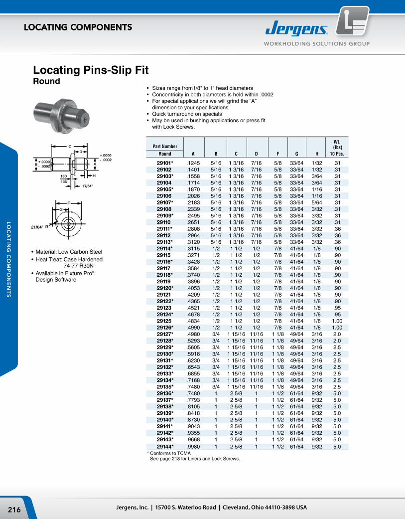
Locating Pins-Slip FitRound
•Material: Low Carbon Steel•Heat Treat: Case Hardened
74-77 R30N•Available in Fixture Pro®
Design Software
• Sizesrangefrom1/8"to1"headdiameters• Concentricityinbothdiametersisheldwithin.0002• Forspecialapplicationswewillgrindthe“A”
dimension to your specifications• Quickturnaroundonspecials• Maybeusedinbushingapplicationsorpressfit
with Lock Screws.
Wt. Part Number (lbs) Round A B C D F G H 10 Pcs.
29101* .1245 5/16 1 3/16 7/16 5/8 33/64 1/32 .31 29102 .1401 5/16 1 3/16 7/16 5/8 33/64 1/32 .31 29103* .1558 5/16 1 3/16 7/16 5/8 33/64 3/64 .31 29104 .1714 5/16 1 3/16 7/16 5/8 33/64 3/64 .31 29105* .1870 5/16 1 3/16 7/16 5/8 33/64 1/16 .31 29106 .2026 5/16 1 3/16 7/16 5/8 33/64 1/16 .31 29107* .2183 5/16 1 3/16 7/16 5/8 33/64 5/64 .31 29108 .2339 5/16 1 3/16 7/16 5/8 33/64 3/32 .31 29109* .2495 5/16 1 3/16 7/16 5/8 33/64 3/32 .31 29110 .2651 5/16 1 3/16 7/16 5/8 33/64 3/32 .31 29111* .2808 5/16 1 3/16 7/16 5/8 33/64 3/32 .36 29112 .2964 5/16 1 3/16 7/16 5/8 33/64 3/32 .36 29113* .3120 5/16 1 3/16 7/16 5/8 33/64 3/32 .36 29114* .3115 1/2 1 1/2 1/2 7/8 41/64 1/8 .90 29115 .3271 1/2 1 1/2 1/2 7/8 41/64 1/8 .90 29116* .3428 1/2 1 1/2 1/2 7/8 41/64 1/8 .90 29117 .3584 1/2 1 1/2 1/2 7/8 41/64 1/8 .90 29118* .3740 1/2 1 1/2 1/2 7/8 41/64 1/8 .90 29119 .3896 1/2 1 1/2 1/2 7/8 41/64 1/8 .90 29120* .4053 1/2 1 1/2 1/2 7/8 41/64 1/8 .90 29121 .4209 1/2 1 1/2 1/2 7/8 41/64 1/8 .90 29122* .4365 1/2 1 1/2 1/2 7/8 41/64 1/8 .90 29123 .4521 1/2 1 1/2 1/2 7/8 41/64 1/8 .95 29124* .4678 1/2 1 1/2 1/2 7/8 41/64 1/8 .95 29125 .4834 1/2 1 1/2 1/2 7/8 41/64 1/8 1.00 29126* .4990 1/2 1 1/2 1/2 7/8 41/64 1/8 1.00 29127* .4980 3/4 1 15/16 11/16 1 1/8 49/64 3/16 2.0 29128* .5293 3/4 1 15/16 11/16 1 1/8 49/64 3/16 2.0 29129* .5605 3/4 1 15/16 11/16 1 1/8 49/64 3/16 2.5 29130* .5918 3/4 1 15/16 11/16 1 1/8 49/64 3/16 2.5 29131* .6230 3/4 1 15/16 11/16 1 1/8 49/64 3/16 2.5 29132* .6543 3/4 1 15/16 11/16 1 1/8 49/64 3/16 2.5 29133* .6855 3/4 1 15/16 11/16 1 1/8 49/64 3/16 2.5 29134* .7168 3/4 1 15/16 11/16 1 1/8 49/64 3/16 2.5 29135* .7480 3/4 1 15/16 11/16 1 1/8 49/64 3/16 2.5 29136* .7480 1 2 5/8 1 1 1/2 61/64 9/32 5.0 29137* .7793 1 2 5/8 1 1 1/2 61/64 9/32 5.0 29138* .8105 1 2 5/8 1 1 1/2 61/64 9/32 5.0 29139* .8418 1 2 5/8 1 1 1/2 61/64 9/32 5.0 29140* .8730 1 2 5/8 1 1 1/2 61/64 9/32 5.0 29141* .9043 1 2 5/8 1 1 1/2 61/64 9/32 5.0 29142* .9355 1 2 5/8 1 1 1/2 61/64 9/32 5.0 29143* .9668 1 2 5/8 1 1 1/2 61/64 9/32 5.0 29144* .9980 1 2 5/8 1 1 1/2 61/64 9/32 5.0* Conforms to TCMA See page 218 for Liners and Lock Screws.
217Phone: 877-426-2504 | Fax: +1 216-481-6193 | E-mail: [email protected] | www.jergensinc.com
WORKHOLDING SOLUTIONS GROUP
LOCATING COMPONENTS
LO
CA
TIN
G C
OM
PO
NE
NT
S
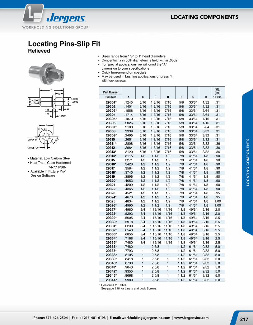
Locating Pins-Slip FitRelieved
•Material:LowCarbonSteel•HeatTreat:CaseHardened 74-77 R30N•AvailableinFixturePro®
Design Software
• Sizesrangefrom1/8"to1"headdiameters• Concentricityinbothdiametersisheldwithin.0002• Forspecialapplicationswewillgrindthe“A”
dimension to your specifications• Quickturn-aroundonspecials• Maybeusedinbushingapplicationsorpressfit
with lock screws.
* Conforms to TCMA See page 218 for Liners and Lock Screws.
Wt. Part Number (lbs) Relieved A B C D F G H 10 Pcs.
29301* .1245 5/16 1 3/16 7/16 5/8 33/64 1/32 .31 29302 .1401 5/16 1 3/16 7/16 5/8 33/64 1/32 .31 29303* .1558 5/16 1 3/16 7/16 5/8 33/64 3/64 .31 29304 .1714 5/16 1 3/16 7/16 5/8 33/64 3/64 .31 29305* .1870 5/16 1 3/16 7/16 5/8 33/64 1/16 .31 29306 .2026 5/16 1 3/16 7/16 5/8 33/64 1/16 .31 29307* .2183 5/16 1 3/16 7/16 5/8 33/64 5/64 .31 29308 .2339 5/16 1 3/16 7/16 5/8 33/64 3/32 .31 29309* .2495 5/16 1 3/16 7/16 5/8 33/64 3/32 .31 29310 .2651 5/16 1 3/16 7/16 5/8 33/64 3/32 .31 29311* .2808 5/16 1 3/16 7/16 5/8 33/64 3/32 .36 29312 .2964 5/16 1 3/16 7/16 5/8 33/64 3/32 .36 29313* .3120 5/16 1 3/16 7/16 5/8 33/64 3/32 .36 29314* .3115 1/2 1 1/2 1/2 7/8 41/64 1/8 .90 29315 .3271 1/2 1 1/2 1/2 7/8 41/64 1/8 .90 29316* .3428 1/2 1 1/2 1/2 7/8 41/64 1/8 .90 29317 .3584 1/2 1 1/2 1/2 7/8 41/64 1/8 .90 29318* .3740 1/2 1 1/2 1/2 7/8 41/64 1/8 .90 29319 .3896 1/2 1 1/2 1/2 7/8 41/64 1/8 .90 29320* .4053 1/2 1 1/2 1/2 7/8 41/64 1/8 .90 29321 .4209 1/2 1 1/2 1/2 7/8 41/64 1/8 .90 29322* .4365 1/2 1 1/2 1/2 7/8 41/64 1/8 .90 29323 .4521 1/2 1 1/2 1/2 7/8 41/64 1/8 .95 29324* .4678 1/2 1 1/2 1/2 7/8 41/64 1/8 .95 29325 .4834 1/2 1 1/2 1/2 7/8 41/64 1/8 1.00 29326* .4990 1/2 1 1/2 1/2 7/8 41/64 1/8 1.00 29327* .4980 3/4 1 15/16 11/16 1 1/8 49/64 3/16 2.0 29328* .5293 3/4 1 15/16 11/16 1 1/8 49/64 3/16 2.0 29329* .5605 3/4 1 15/16 11/16 1 1/8 49/64 3/16 2.5 29330* .5918 3/4 1 15/16 11/16 1 1/8 49/64 3/16 2.5 29331* .6230 3/4 1 15/16 11/16 1 1/8 49/64 3/16 2.5 29332* .6543 3/4 1 15/16 11/16 1 1/8 49/64 3/16 2.5 29333* .6855 3/4 1 15/16 11/16 1 1/8 49/64 3/16 2.5 29334* .7168 3/4 1 15/16 11/16 1 1/8 49/64 3/16 2.5 29335* .7480 3/4 1 15/16 11/16 1 1/8 49/64 3/16 2.5 29336* .7480 1 2 5/8 1 1 1/2 61/64 9/32 5.0 29337* .7793 1 2 5/8 1 1 1/2 61/64 9/32 5.0 29338* .8105 1 2 5/8 1 1 1/2 61/64 9/32 5.0 29339* .8418 1 2 5/8 1 1 1/2 61/64 9/32 5.0 29340* .8730 1 2 5/8 1 1 1/2 61/64 9/32 5.0 29341* .9043 1 2 5/8 1 1 1/2 61/64 9/32 5.0 29342* .9355 1 2 5/8 1 1 1/2 61/64 9/32 5.0 29343* .9668 1 2 5/8 1 1 1/2 61/64 9/32 5.0 29344* .9980 1 2 5/8 1 1 1/2 61/64 9/32 5.0
Jergens, Inc. | 15700 S. Waterloo Road | Cleveland, Ohio 44110-3898 USA218
WORKHOLDING SOLUTIONS GROUP
LOCATING COMPONENTS
LO
CA
TIN
G C
OM
PO
NE
NT
S
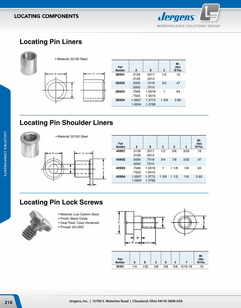
Wt. Part (lbs) Number A B C D E F 10 Pcs.
10101 1/4 .135 3/8 3/8 5/8 5/16-18 .16
Wt. Part (lbs) Number A B C D E 10 Pcs.
40901 .3129 .5017 1/2 5/8 3/32 .16 .3126 .5014 40902 .5005 .7518 3/4 7/8 3/32 .47 .5002 .7515 40903 .7506 1.0018 1 1 1/8 1/8 .94 .7503 1.0015 40904 1.0007 1.3772 1 3/8 1 1/2 1/8 2.65 1.0004 1.3768
Locating Pin Lock Screws
•Material:LowCarbonSteel•Finish:BlackOxide•HeatTreat:CaseHardened•Thread:2A-UNC
Locating Pin Liners
Locating Pin Shoulder Liners
•Material:52100Steel
•Material:52100Steel
Wt. Part (lbs) Number A B C 10 Pcs.
28501 .3129 .5017 1/2 .16 .3126 .5014 28502 .5005 .7518 3/4 .47 .5002 .7515 28503 .7506 1.0018 1 .94 .7503 1.0015 28504 1.0007 1.3772 1 3/8 2.80 1.0004 1.3768
ØCE
ØD ØAØB
F
G
H
+.000 -.001
+.0000 -.0003
ØA ØG
ED
F
ØB
.03
+.0000 -.0005
+.0000 -.0003
ØC
219Phone: 877-426-2504 | Fax: +1 216-481-6193 | E-mail: [email protected] | www.jergensinc.com
WORKHOLDING SOLUTIONS GROUP
LOCATING COMPONENTS
LO
CA
TIN
G C
OM
PO
NE
NT
S
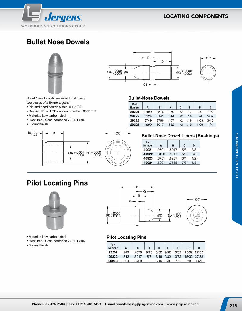
Bullet Nose Dowels
Bullet Nose Dowels are used for aligning two pieces of a fixture together.•Pinandheadcentricwithin.0005TIR•BushingIDandODconcentricwithin.0003TIR•Material:Lowcarbonsteel•HeatTreat:Casehardened72-82R30N•Groundfinish
Part Number A B C D E F G
29221 .2499 .2516 .280 1/2 .12 .90 1/8 29222 .3124 .3141 .344 1/2 .16 .94 5/32 29223 .3749 .3766 .407 1/2 .19 1.03 3/16 29224 .4999 .5017 .532 1/2 .19 1.09 1/4
•Material:Lowcarbonsteel•HeatTreat:Casehardened72-82R30N•Groundfinish
Pilot Locating Pins
Bullet-Nose Dowels
Bullet-Nose Dowel Liners (Bushings) Part Number A B C D
40921 .2501 .5017 5/8 3/8 40922 .3126 .5017 5/8 3/8 40923 .3751 .6267 3/4 1/2 40924 .5001 .7518 7/8 5/8
Pilot Locating Pins
Part Number A B C D E F G H
29231 .249 .4078 9/16 5/32 9/32 3/32 15/32 27/32 29232 .312 .5017 5/8 3/16 9/32 3/32 15/32 27/32 29233 .624 .8768 1 5/16 3/8 1/8 7/8 1 5/8
Bullet Nose Liners
Bullet NoseRound Pin
Bullet NoseRelieved Pin
ØAØB
CD
E
+.0000 -.0003
+.0000 -.0003 60˚
ØF
ØAØB
C
D
E
+.0000 -.0003
ØF
+.0000 -.0003
Jergens, Inc. | 15700 S. Waterloo Road | Cleveland, Ohio 44110-3898 USA220
WORKHOLDING SOLUTIONS GROUP
LOCATING COMPONENTS
LO
CA
TIN
G C
OM
PO
NE
NT
S
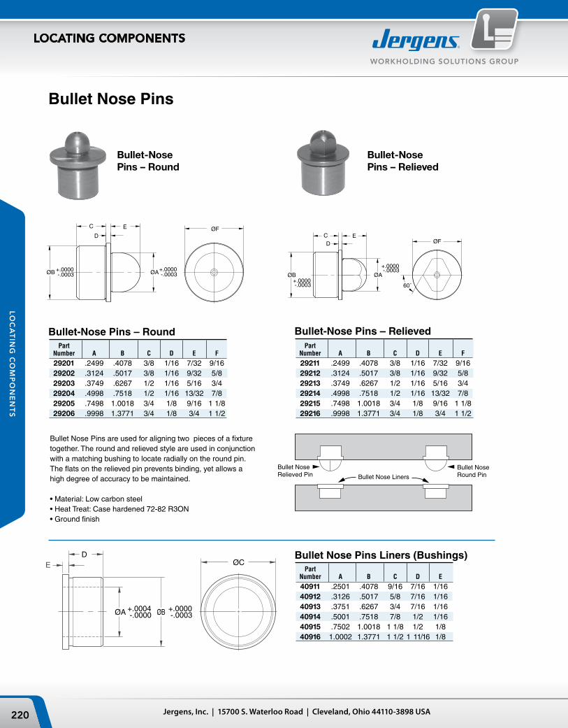
Bullet Nose Pins are used for aligning two pieces of a fixture together. The round and relieved style are used in conjunction with a matching bushing to locate radially on the round pin. The flats on the relieved pin prevents binding, yet allows a high degree of accuracy to be maintained.
•Material:Lowcarbonsteel•HeatTreat:Casehardened72-82R3ON•Groundfinish
Bullet Nose Pins
Bullet-Nose Pins – Round Part Number A B C D E F
29201 .2499 .4078 3/8 1/16 7/32 9/16 29202 .3124 .5017 3/8 1/16 9/32 5/8 29203 .3749 .6267 1/2 1/16 5/16 3/4 29204 .4998 .7518 1/2 1/16 13/32 7/8 29205 .7498 1.0018 3/4 1/8 9/16 1 1/8 29206 .9998 1.3771 3/4 1/8 3/4 1 1/2
Bullet-Nose Pins – Relieved Part Number A B C D E F
29211 .2499 .4078 3/8 1/16 7/32 9/16 29212 .3124 .5017 3/8 1/16 9/32 5/8 29213 .3749 .6267 1/2 1/16 5/16 3/4 29214 .4998 .7518 1/2 1/16 13/32 7/8 29215 .7498 1.0018 3/4 1/8 9/16 1 1/8 29216 .9998 1.3771 3/4 1/8 3/4 1 1/2
Bullet Nose Pins Liners (Bushings) Part Number A B C D E
40911 .2501 .4078 9/16 7/16 1/16 40912 .3126 .5017 5/8 7/16 1/16 40913 .3751 .6267 3/4 7/16 1/16 40914 .5001 .7518 7/8 1/2 1/16 40915 .7502 1.0018 1 1/8 1/2 1/8 40916 1.0002 1.3771 1 1/2 1 11/16 1/8
Bullet-Nose Pins – Round
Bullet-Nose Pins – Relieved
Ø A
C
ØB ØF
D
E THREAD
Ø A
C
D
ØB ØF
ØA
C
D
ØB Ø F
221Phone: 877-426-2504 | Fax: +1 216-481-6193 | E-mail: [email protected] | www.jergensinc.com
WORKHOLDING SOLUTIONS GROUP
LOCATING COMPONENTS
LO
CA
TIN
G C
OM
PO
NE
NT
S
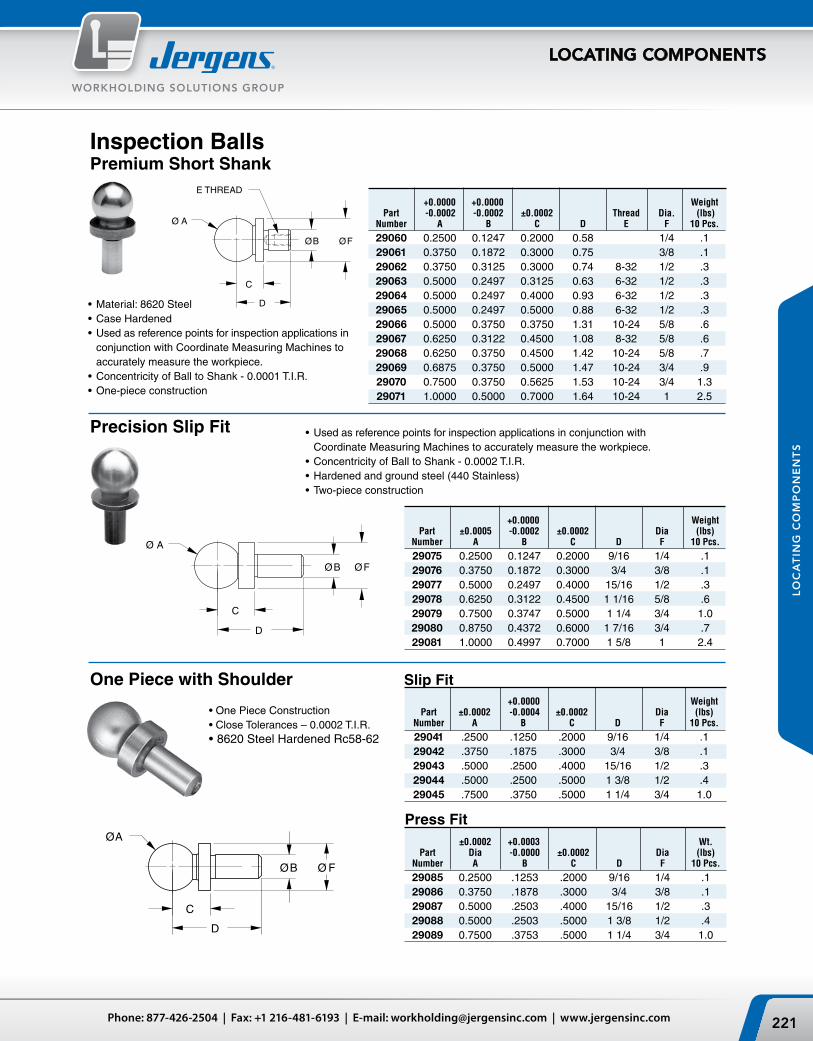
Inspection BallsPremium Short Shank
•OnePieceConstruction•CloseTolerances–0.0002T.I.R.•8620SteelHardenedRc58-62
Precision Slip Fit
One Piece with Shoulder
•UsedasreferencepointsforinspectionapplicationsinconjunctionwithCoordinate Measuring Machines to accurately measure the workpiece.
•ConcentricityofBalltoShank-0.0002T.I.R.•Hardenedandgroundsteel(440Stainless)•Two-piececonstruction
•Material:8620Steel•CaseHardened•Usedasreferencepointsforinspectionapplicationsin
conjunction with Coordinate Measuring Machines to accurately measure the workpiece.
•ConcentricityofBalltoShank-0.0001T.I.R.•One-piececonstruction
+0.0000 Weight Part ±0.0005 -0.0002 ±0.0002 Dia (lbs) Number A B C D F 10 Pcs.
29075 0.2500 0.1247 0.2000 9/16 1/4 .1 29076 0.3750 0.1872 0.3000 3/4 3/8 .1 29077 0.5000 0.2497 0.4000 15/16 1/2 .3 29078 0.6250 0.3122 0.4500 1 1/16 5/8 .6 29079 0.7500 0.3747 0.5000 1 1/4 3/4 1.0 29080 0.8750 0.4372 0.6000 1 7/16 3/4 .7 29081 1.0000 0.4997 0.7000 1 5/8 1 2.4
+0.0000 +0.0000 Weight Part -0.0002 -0.0002 ±0.0002 Thread Dia. (lbs) Number A B C D E F 10 Pcs.
29060 0.2500 0.1247 0.2000 0.58 1/4 .1 29061 0.3750 0.1872 0.3000 0.75 3/8 .1 29062 0.3750 0.3125 0.3000 0.74 8-32 1/2 .3 29063 0.5000 0.2497 0.3125 0.63 6-32 1/2 .3 29064 0.5000 0.2497 0.4000 0.93 6-32 1/2 .3 29065 0.5000 0.2497 0.5000 0.88 6-32 1/2 .3 29066 0.5000 0.3750 0.3750 1.31 10-24 5/8 .6 29067 0.6250 0.3122 0.4500 1.08 8-32 5/8 .6 29068 0.6250 0.3750 0.4500 1.42 10-24 5/8 .7 29069 0.6875 0.3750 0.5000 1.47 10-24 3/4 .9 29070 0.7500 0.3750 0.5625 1.53 10-24 3/4 1.3 29071 1.0000 0.5000 0.7000 1.64 10-24 1 2.5
Slip Fit
Press Fit
+0.0000 Weight Part ±0.0002 -0.0004 ±0.0002 Dia (lbs) Number A B C D F 10 Pcs.
29041 .2500 .1250 .2000 9/16 1/4 .1 29042 .3750 .1875 .3000 3/4 3/8 .1 29043 .5000 .2500 .4000 15/16 1/2 .3 29044 .5000 .2500 .5000 1 3/8 1/2 .4 29045 .7500 .3750 .5000 1 1/4 3/4 1.0
±0.0002 +0.0003 Wt. Part Dia -0.0000 ±0.0002 Dia (lbs) Number A B C D F 10 Pcs.
29085 0.2500 .1253 .2000 9/16 1/4 .1 29086 0.3750 .1878 .3000 3/4 3/8 .1 29087 0.5000 .2503 .4000 15/16 1/2 .3 29088 0.5000 .2503 .5000 1 3/8 1/2 .4 29089 0.7500 .3753 .5000 1 1/4 3/4 1.0
D
C
Ø B ØE
ØA
F THREAD
D
Ø B
Ø A
.28.1563 ±.0002
Ø.1255 /.1253 Ø.19
Ø.1250 ± .0003
Jergens, Inc. | 15700 S. Waterloo Road | Cleveland, Ohio 44110-3898 USA222
WORKHOLDING SOLUTIONS GROUP
LOCATING COMPONENTS
LO
CA
TIN
G C
OM
PO
NE
NT
S
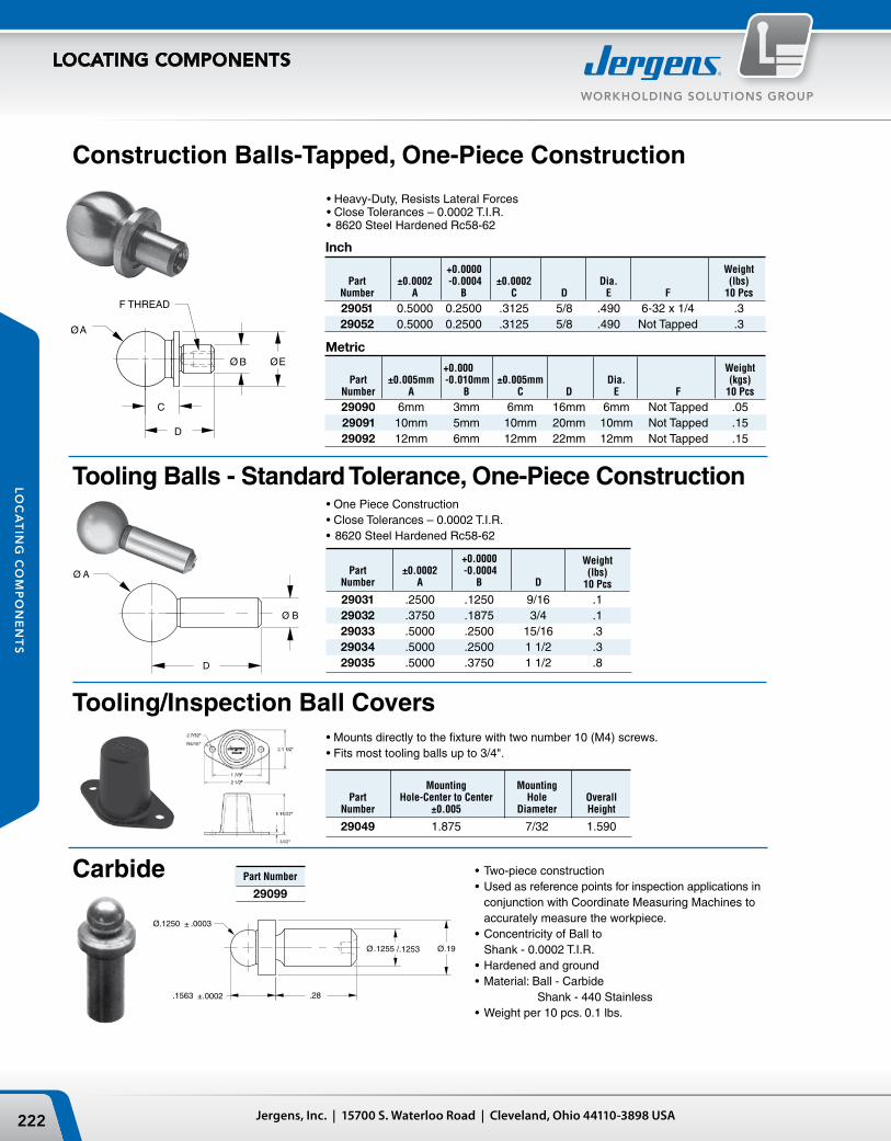
•Heavy-Duty,ResistsLateralForces•CloseTolerances–0.0002T.I.R.•8620SteelHardenedRc58-62
Construction Balls-Tapped, One-Piece Construction
Inch
Tooling Balls - Standard Tolerance, One-Piece Construction•OnePieceConstruction•CloseTolerances–0.0002T.I.R.•8620SteelHardenedRc58-62
•Mountsdirectlytothefixturewithtwonumber10(M4)screws.•Fitsmosttoolingballsupto3/4".
Metric
Mounting Mounting Part Hole-Center to Center Hole Overall Number ±0.005 Diameter Height
29049 1.875 7/32 1.590
Carbide •Two-piececonstruction•Usedasreferencepointsforinspectionapplicationsin
conjunction with Coordinate Measuring Machines to accurately measure the workpiece.
•ConcentricityofBallto Shank - 0.0002 T.I.R.
•Hardenedandground•Material:Ball-Carbide
Shank - 440 Stainless•Weightper10pcs.0.1lbs.
Part Number
29099
+0.0000 Weight Part ±0.0002 -0.0004 (lbs) Number A B D 10 Pcs
29031 .2500 .1250 9/16 .1 29032 .3750 .1875 3/4 .1 29033 .5000 .2500 15/16 .3 29034 .5000 .2500 1 1/2 .3 29035 .5000 .3750 1 1/2 .8
+0.0000 Weight Part ±0.0002 -0.0004 ±0.0002 Dia. (lbs) Number A B C D E F 10 Pcs
29051 0.5000 0.2500 .3125 5/8 .490 6-32 x 1/4 .3 29052 0.5000 0.2500 .3125 5/8 .490 Not Tapped .3
+0.000 Weight Part ±0.005mm -0.010mm ±0.005mm Dia. (kgs) Number A B C D E F 10 Pcs
29090 6mm 3mm 6mm 16mm 6mm Not Tapped .05 29091 10mm 5mm 10mm 20mm 10mm Not Tapped .15 29092 12mm 6mm 12mm 22mm 12mm Not Tapped .15
Tooling/Inspection Ball Covers
29003TOOLING BALLS
FIXTURE BALLS (PLAIN SHANK)PG 2.29
PARTNUMBER
A
± .0001
B+.0000-.0003
D
± .005
29001 .2500 .1247 .560
29002 .3750 .1872 .750
29003 .5000 .2497 .940
29004 .6250 .3122 1.060
29005 .7500 .3747 1.250
29006 .8750 .4372 1.440
29007 1.0000 .4997 1.620
D
Ø B
Ø A
29013CHECKING BALLS
WITH REFERENCE SHOULDERPG 2.29
PART NUMBER
AB
+.0000-.0002
C± .0002
D± .005
29010 .1250 .1255 .0938 .375
29011 .2500 .1247 .2000 .560
29012 .3750 .1872 .3000 .750
29013 .5000 .2497 .4000 .940
29014 .6250 .3122 .4500 1.060
29015 .7500 .3747 .5000 1.250
29016 .8750 .4372 .6000 1.440
29017 1.0000 .4997 .7000 1.620
C
D
ØB
A DIM1/8 thru 5/8 ±.00002 3/4 thru 1" ±.00005
Ø.5000 ±.0002
.3125 ±.0002
.96
Ø.2499±.0001 Ø1/2"
6-32 UNC-2B TAP3/16 DEEP
223Phone: 877-426-2504 | Fax: +1 216-481-6193 | E-mail: [email protected] | www.jergensinc.com
WORKHOLDING SOLUTIONS GROUP
LOCATING COMPONENTS
LO
CA
TIN
G C
OM
PO
NE
NT
S
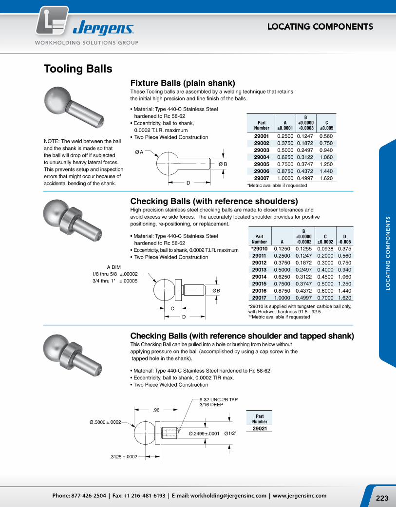
Checking Balls (with reference shoulders)High precision stainless steel checking balls are made to closer tolerances and avoid excessive side forces. The accurately located shoulder provides for positive positioning, re-positioning, or replacement.
•Material:Type440-CStainlessSteel hardened to Rc 58-62
•Eccentricity,balltoshank,0.0002T.I.R.maximum•TwoPieceWeldedConstruction
B Part A +0.0000 C Number ±0.0001 -0.0003 ±0.005
29001 0.2500 0.1247 0.560 29002 0.3750 0.1872 0.750 29003 0.5000 0.2497 0.940 29004 0.6250 0.3122 1.060 29005 0.7500 0.3747 1.250 29006 0.8750 0.4372 1.440 29007 1.0000 0.4997 1.620*Metric available if requested
Tooling Balls
•Material:Type440-CStainlessSteel hardened to Rc 58-62
•Eccentricity,balltoshank, 0.0002 T.I.R. maximum
•TwoPieceWeldedConstruction
Checking Balls (with reference shoulder and tapped shank)This Checking Ball can be pulled into a hole or bushing from below without applying pressure on the ball (accomplished by using a cap screw in the tapped hole in the shank).
•Material:Type440-CStainlessSteelhardenedtoRc58-62•Eccentricity,balltoshank,0.0002TIRmax.•TwoPieceWeldedConstruction
PartNumber
29021
NOTE: The weld between the ball and the shank is made so that the ball will drop off if subjected to unusually heavy lateral forces. This prevents setup and inspection errors that might occur because of accidental bending of the shank.
Fixture Balls (plain shank)These Tooling balls are assembled by a welding technique that retains the initial high precision and fine finish of the balls.
*29010 is supplied with tungsten carbide ball only, with Rockwell hardness 91.5 - 92.5**Metric available if requested
B Part +0.0000 C D Number A -0.0002 ±0.0002 -0.005
*29010 0.1250 0.1255 0.0938 0.375 29011 0.2500 0.1247 0.2000 0.560 29012 0.3750 0.1872 0.3000 0.750 29013 0.5000 0.2497 0.4000 0.940 29014 0.6250 0.3122 0.4500 1.060 29015 0.7500 0.3747 0.5000 1.250 29016 0.8750 0.4372 0.6000 1.440 29017 1.0000 0.4997 0.7000 1.620

Jergens, Inc. | 15700 S. Waterloo Road | Cleveland, Ohio 44110-3898 USA224
WORKHOLDING SOLUTIONS GROUP
Jergens Workolding Solutions Group...Your Uptime Consultants
“The applications of the Ball Lock®
System are basically limitless – you’re
completely free from the design
limitations of common tooling. We have
increased utilization rates 75% – 90%.”
Jergens Ball Lock® Customer
To compete in today’s global industry you need to accommodate shorter lead times, smaller batch sizes and frequent set up changes.
Get more savings by changing what’s UNDER the spindle, not ON it.
Shave 90% from your set up times by implementing a quick change fixturing system for a fraction of the cost of your cutting tool investment. Jergens’ workholding efficiency improvement process helps:
• Increasespindleuptime
• Speedimplementationofleanmanufacturing
• Improveproductivity
• Optimizeworkholding
• Reducedowntime
• Maximizecostsavings
• Eliminatesetuperrorsandinefficiencies
• Fasterpart-to-partchangeover