Embed Size (px)
Citation preview

Composite Structures 120 (2015) 79–89
Contents lists available at ScienceDirect
Composite Structures
journal homepage: www.elsevier .com/locate /compstruct
Localization of buckling modes in plates and laminates
http://dx.doi.org/10.1016/j.compstruct.2014.09.0350263-8223/� 2014 Elsevier Ltd. All rights reserved.
⇑ Corresponding author.E-mail address: [email protected] (S.S. Gupta).
S. Paik a, S.S. Gupta a,⇑, R.C. Batra b
a Mechanics and Applied Mathematics Group, Department of Mechanical Engineering, Indian Institute of Technology-Kanpur, Kanpur 208016, Indiab Department of Biomedical Engineering and Mechanics, M/C 0219, Virginia Polytechnic Institute and State University, Blacksburg, VA 24061, USA
a r t i c l e i n f o a b s t r a c t
Article history:Available online 30 September 2014This paper is dedicated to the memory of thelate Professor Himanshu Hatwal,Department of Mechanical Engineering, IITKanpur, India.
Keywords:Mindlin plate theoryBucklingLaminatesMode localization
We use the Mindlin plate theory and the finite element method to delineate the effect of fixing points ona transverse normal to the mid-surface of the plate on the localization of buckling modes in clamped–clamped rectangular plates made of linear elastic, homogeneous and either isotropic (monolithic) ororthotropic (fiber-reinforced composite) materials. The in-plane loads considered on the bounding edgesare: (i) normal tractions on the length, (ii) normal tractions on the width, (iii) equal normal tractions onthe length and the width (equal biaxial loading), (iv) shear (tangential), and (v) combined same normaland shear tractions on all sides. It is found that clamping points on a transverse normal passing throughthe mid-point of a line parallel to the short side increases the critical buckling load of plates of only lowaspect ratios over that of the corresponding plates unconstrained at interior points. However, for plates ofall aspect ratios (thickness/length) fixing points on a transverse normal divides it into two regions withnegligible transverse deflections in only one of the two regions. Only for loads (i)–(iii) the dividing line isparallel to the short side of the plate. For both thin and thick isotropic plates the slope of the dividing lineis found to monotonically increase with an increase in the aspect ratio of a plate until it reaches a satu-ration value. A parameter based on the modal strain energy is used to quantify the degree of localizationof a buckling mode. For an isotropic plate the degree of localization is found to increase with the increasein the aspect ratio for load cases (i)–(iii) but is found to be moderate for load cases (iv) and (v). For anorthotropic layer the degree of localization with an increase in the aspect ratio of the plate increases morefor the 90� lamina than that for the 0� and the 45� laminae. Also, the mode localization in the (45�,�45�)laminate is stronger than that in the (0�,90�) laminate for the five load cases. However, moderate degreeof mode localization is found in symmetric and anti-symmetric cross-ply and angle-ply laminates.
� 2014 Elsevier Ltd. All rights reserved.
1. Introduction
An irregularity in an ordered medium generally leads to locali-zation of vibration modes [1,2] in linear mechanical systems, i.e.,the vibration modes are confined in a certain region of the system.Since a buckling problem is also an eigenvalue problem it may beenvisaged that a disturbance in the periodic order in a mechanicalsystem will lead to buckling mode localization [3]. Pierre and Plaut[3] considered a beam made of two spans of identical uniformcross-sections but of different lengths, fixed at one end while sup-ported on rollers at the intermediate point and at the other end,with the two spans coupled with a torsional spring. For the beamloaded by an axial compressive force, they used perturbation anal-ysis and found mode localization for weak coupling between thetwo spans. They concluded that the loci of the first two criticalloads as a function of the slight irregular spacing between the
two supports are far separated for strong coupling and are veryclose to each other for weak coupling between the spans. Similarly,Nayfeh and Hawwa [4] studied localization of buckling modes inthree and four span simply supported beams coupled through tor-sional springs, and Li et al. [5] extended this work to an N-spanbeam. By using Kirchhoff’s plate theory Elishakoff et al. [6] foundthat the buckling mode localization is sensitive to the misplace-ment of stiffeners in uniaxially compressed rib-stiffened rectangu-lar thin plates. These plates with different boundary conditionswere subsequently analyzed by Xie and Ibrahim [7] using the finitestrip method. Xie [8] found that a stronger inhomogeneity leads toa larger degree of buckling mode localization in a simply-sup-ported nonhomogeneous beam resting on an elastic foundationand loaded by in-plane compressive loads. Brasil and Hawwa [9]studied buckling mode localization in two-dimensional trussesby slightly varying the length of a truss member.
Filoche and Mayboroda [10] have studied vibration mode local-ization in a linear elastic, isotropic and homogeneous Kirchhoffplate, and showed that fixing points on a transverse normal divides

Fig. 1. Schematic of a clamped–clamped plate depicting geometric parameters, orientation of fibers and fiber axis for laminae/laminates, the location of the interior point P onthe plate mid-surface, different uniformly distributed loads on the edge surfaces, and regions X1 (shaded) and X2 where buckling modes get localized after fixing points onthe vertical line passing through the point P. A possible way of fixing points on the vertical line passing through P is shown using two pins supporting the plate from oppositesides, while the other end of pins is fixed. For an isotropic plate the angle h of the dividing line mn passing through P equals p/2 for loading scenarios (i)–(iii), and it equals theinclination of the tangent to nodal line w(x,y) = 0 through P for the loading situations (iv) and (v).
Table 1Nondimensional critical buckling load factor k (¼ N0b2
=p2D, where N0 = the criticalbuckling load/length, b = width of the plate, and D = bending rigidity of the plate) forCCCC rectangular isotropic plates of b/h = 100 subjected to loads (i) and (iii). Poisson’sratio m = 0.3.
Eccentricity Load type (i) (uniaxialcompression)
Load type (iii) (shear tractions)
Timoshenko andGere [14]
Present Shufrin andEisenberger [15]
Present
0.75 11.69 11.63 – –1.00 10.07 10.05 14.64 14.571.25 9.25 9.23 – –1.50 8.33 8.32 – –1.75 8.11 8.09 – –2.00 7.88 7.85 10.25 10.212.25 7.63 7.61 – –2.50 7.57 7.56 – –2.75 7.44 7.42 – –3.00 7.37 7.34 9.53 9.503.25 7.35 7.32 – –3.50 7.27 7.24 – –3.75 7.24 7.21 – –4.00 7.23 7.19 9.30 9.276.00 – – 9.12 9.0910.00 – – 9.03 9.00
80 S. Paik et al. / Composite Structures 120 (2015) 79–89
the plate into two independently vibrating regions. Subsequently,Sharma et al. [11] used the Mindlin plate theory to delineate effectsof the fiber angle and the stacking sequence on mode localization,and found that placing a lumped mass at an interior point of a lam-inate also localized modes of vibration. Verma et al. [12] usedmolecular mechanics simulations with the MM3 potential and thesoftware TINKER to analyze vibration mode localization in a single-and multi- layered graphene nanoribbon due to either fixing anatom or attaching a buckyball to an atom in the interior of the nano-ribbon. Here we use the Mindlin plate theory to study bucklingmode localization in clamped–clamped (i) linear elastic, homoge-neous and isotropic thin rectangular plates, and (ii) orthotropiclaminae and laminates due to fixing points on a transverse normalpassing through an interior point P. The following five in-planeloads on the plate edges are considered: (i) normal to the long side,(ii) normal to the short side, (iii) normal to all sides (equal biaxialloading), (iv) shear or tangential on all sides, and (v) combined biax-
ial and tangential tractions of the same magnitude. For all loadtypes considered, the interior point is found to divide a plate/lami-nate into two distinct regions – one with buckling mode of finiteamplitude and the other of negligible amplitude. We define thedegree of mode localization as the ratio of the modal strain energiesof one such region to that of the entire plate/laminate. It is foundthat the degree of mode localization for isotropic monolithic platesincreases with an increase in the aspect ratio of plates. For an ortho-tropic laminae the degree of mode localization is higher for a 90�lamina than that for 0� and 45� laminae for the same relative loca-tion of the fixed point. However, there is no appreciable mode local-ization in symmetric and anti-symmetric, cross-ply and angle-plylaminates with more than two layers. These results can be usedto place internal constraints on panels of aircraft/spacecraft skinsand on superstructure/bulkhead of ships.
The rest of the paper is organized as follows. In Section 2 webriefly describe the procedure used to analyze the problem. In Sec-tion 3, we discuss the buckling mode localization in isotropic platesdue to the five load types, and provide the orientation of the in-plane line passing through the interior fixed point which dividesthe plate into two independent regions. Buckling mode localizationin orthotropic laminae and laminates is discussed in Section 4.Conclusions of this work are summarized in Section 5.
2. Procedure
Static deformations of a clamped rectangular plate/laminatewith in-plane applied forces at the edges as shown in Fig. 1 areanalyzed by using the Mindlin plate theory and the finite elementmethod (FEM) with 8-node quadrilateral elements. The bucklingload of a linear elastic plate is given by the eigenvalue problem
½K � kKG�fdg ¼ 0: ð1Þ
Here, K and KG are the global stiffness and the global geometricmatrices, respectively. The eigenvalue k and the associated eigen-vector {d} are the buckling load and the associated buckling mode,respectively. Each node of the finite element on the midsurface ofthe plate has three degrees-of-freedom (DOF), namely, w, the dis-placement along the Z-axis, wX, the rotation about the X-axis ofthe transverse normal to the mid-plane, and wY, the rotation aboutthe Y-axis of the transverse normal to the mid-plane. The plate

Table 2Nondimensional critical buckling load factor k ð¼ N0b2
=p2DÞ for CCCC rectangularisotropic plates with b/h = 100 and m = 0.3 and subjected to combined loads, i.e.,Nx = Ny = N0 and Nxy = N0xy.
N0/N0xy Timoshenko and Gere [14] Present
0.0 14.71 14.570.5 7.09 7.381.0 4.50 4.631.5 3.24 3.302.0 2.51 2.54
S. Paik et al. / Composite Structures 120 (2015) 79–89 81
length equals the inverse of its width, the aspect ratio (length/width)following [10] is termed the eccentricity, and the shear correctionfactor is assigned the value 5/6. Boundary conditions at the clampededges and at a clamped interior point are: w = wX = wY = 0. For platesof various eccentricities, the FE mesh was refined until the succes-sive refinement yielded the difference between the loads for the first100 buckled modes of less than 1%. For the plate/laminate witheccentricity of 20 the FE mesh of 18 uniform elements along thewidth b and 200 uniform elements along the length a gave the con-verged solution. The bending and the shear parts of an element stiff-
Fig. 2. Normalized buckling modes of the clamped rectangular plate of eccentricity = 20 fand those in panels (d)–(f) are for the clamped plate when points on the transverse nor
ness matrix for a thin plate are computed by using the 3 � 3 and the2 � 2 Gauss quadrature rule, respectively. The FE code written inMATLAB [13] has been verified by comparing (e.g., see Tables 1and 2) computed values of the buckling load factor for differentloads applied on edges of an unconstrained monolithic plate withthose available in the literature. It is found that the computed valuesof the buckling load factor agree well with those reported by otherresearchers. Similarly, the computed non-dimensional buckling loadfactor (k = Nxb
2/D0) of 62.045 for clamped–clamped [30�/�30�/30�]laminated square plate with E1/E2 = 2.45, G12/E2 = 0.48, m12 = 0.23,b/h = 100, D0 = E1h3/12(1 � m12m21), subjected to load type (i) wasfound to be close to 61.893 reported by Shrufin et al. [16]. Here var-ious symbols have the usual meaning, and h equals the thickness ofthe plate. Buckling loads found using this code for other boundaryconditions at the plate edges and various loads applied on the edgesurfaces were also found to agree well with those reported in the lit-erature. These results are omitted for the sake of brevity. This code isused to study buckling mode localization in rectangular plates/lam-inates of b/h = 100 (50) for isotropic (orthotropic) plates when pointson the transverse normal through the interior point P, shown inFig. 1, are fixed. The location of the interior point P is found not toaffect the mode localization phenomenon.
or different edge loads. Modes in panels (a)–(c) are for the plate with clamped edges,mal through the point P, shown in Fig. 1, are also clamped.

0 3 6 9 12 150
5
10
15
20
25
Eccentricity (e)
Per
cent
age
incr
ease
of
k Ny = Nxy = 0, Nx
≠ 0
Nx = Nxy = 0, Ny≠ 0
Nxy = 0, Nx = Ny≠ 0
Nx = Ny = 0, Nxy≠ 0
Nx = Ny = Nxy≠ 0
Fig. 3. Effect of clamping points on the transverse normal through the interior pointP (as shown in Fig. 1) of an isotropic plate on the critical buckling load with increasein the plate eccentricity. Values along the y-axis are computed with reference to thecritical buckling load of an un-constrained clamped plate.
82 S. Paik et al. / Composite Structures 120 (2015) 79–89
3. Buckling mode localization in isotropic plates
3.1. Loads (i) through (iii)
For an isotropic material we set Young’s modulus E = 10,920units and Poisson’s ratio m = 0.3. In Fig. 2 we have exhibited buck-
Fig. 4. (a) Distribution of the mode localization parameter b1 for load case (i) when no iwith points on the transverse normal through point P clamped.
ling mode localization in the plate of eccentricity e = 20 for loadingscenarios (i) through (iii). It is clearly seen that fixing points on thetransverse normal through the interior point P (hereafter referredto as fixing point P) localizes buckling modes on either side of it(cf. Fig. 2d–f). The plate is divided into two regions X1 and X2 bypoint P (cf. Fig. 1). As shown in Fig. 3, the critical buckling load fac-tor increases after clamping an interior point for each of the threeloading cases for plates of aspect ratio < 4. However, with increas-ing aspect ratio the effect of clamping point P on the critical buck-ing load diminishes. The critical buckling load is the least for thecombined loading.
We quantify buckling mode localization using the energy basednon-dimensional parameter b1, defined by
b1 ¼Pn
i¼1fdgTi ½k�elfdgiPN
j¼1fdgTj ½k�elfdgj
: ð2Þ
That is, b1 equals the ratio of the modal strain energy of region X1
composed of n elements to that of the modal strain energy of regionX that is divided into N elements. It should be noted thatX = X1 [X2. For an element partially in X1 and X2, the strainenergy of deformation of an element attributed to X1 is taken tobe proportional to the area of the element in X1. In Eq. (2) [k]el isthe stiffness matrix for element el that includes the shear correctionfactor. Value of b1 � 0 implies negligible deformations in O1 (cf.Fig. 2d and f) whereas b1 � 1 implies that deformations are predom-inantly in O1 (cf. Fig. 2e). The distribution of b1 for a plate withoutclamped interior point and subjected to load (i) is shown in Fig. 4a.
nterior point is clamped, (b)–(d) distribution of b1 for the load cases (i), (ii) and (iii)

Fig. 5. (a)–(c) Variation of the connection coefficient for load cases (i), (ii) and (iii) respectively, with and without points on the transverse normal through point P clamped.The value of the connection coefficient without clamping any interior point saturates to nearly 0.2 for all loading scenarios. With increasing eccentricity clamping points onthe transverse normal through point P divides the region of the plate into two increasingly separated regions in the sense that more modes have negligible amplitude either inregion X1 or in region X2.
2 6 10 14 18 22 26 3050.0
50.2
50.4
50.6
50.8
51.0
Eccentricity ( e) Eccentricity ( e)
θ (d
eg)
Nx = Ny = 0, Nxy≠ 0
(c)
2 6 10 14 18 22 26 3062.4
62.6
62.8
63.0
63.2
63.4
63.6
θ (d
eg)
Nx = Ny = Nxy≠ 0
(d)
(a)
(b)
P
Fig. 6. (a) and (b) top views of the buckling modes of a plate with edge loads Nx = Ny = 0, Nxy – 0 and eccentricity = 20 without and with points on a transverse normal throughpoint P clamped, respectively. Contour plot shows the out-of-plane displacement of the plate. The angle h, shown in Fig. 1, of nodal lines with the horizontal line remainsunaffected by clamping of points on the transverse normal through point P. Panels (c) and (d) show variation of the angle h with the eccentricity for biaxial and combined loads.
S. Paik et al. / Composite Structures 120 (2015) 79–89 83

Fig. 7. Normalized 1st buckling mode of a clamped rectangular plate of eccentricity = 20 for different loads on the edges. Modes in figures (a) and (b) are for the cases whenonly edges of the plate are clamped and those in figures (c) and (d) are for the case when points on the transverse normal through an interior point P are also clamped.
Fig. 8. (a) and (b) distribution of the mode localization parameter b1 for the loads (iv) and (v). For both types of loads, there is a moderate localization of modes. (c) and (d)variation of the connection coefficient for the load (iv) and (v) with and without clamping points on the transverse normal through point P.
84 S. Paik et al. / Composite Structures 120 (2015) 79–89

0 0.2 0.4 0.6 0.8 10
10
20
30
40
50
60
70
No
of m
odes
φ = 0o
e = 20 Ny = Nxy = 0, Nx
≠ 0
Fixed interior point P
0 0.2 0.4 0.6 0.8 10
10
20
30
40
50
60
70
No
of m
odes
φ = 0o
e = 20 Nx = Nxy = 0, Ny
≠ 0
Fixed interior point P
0 0.2 0.4 0.6 0.8 10
10
20
30
40
50
60
70
No
of m
odes
φ = 0o
e = 20 N
xy = 0, Nx = N
y≠ 0
Fixed interior point P
0 0.2 0.4 0.6 0.8 10
10
20
30
40
50
60
70
No
of m
odes
φ = 0o
e = 20 Nx = Ny = 0, Nxy
≠ 0
Fixed interior point P
0 0.2 0.4 0.6 0.8 10
10
20
30
40
50
60
70
β1
No
of m
odes
φ = 0o
e = 20 Nx = Ny = Nxy
≠ 0
Fixed interior point P
0 0.2 0.4 0.6 0.8 10
10
20
30
40
50
60
70
φ = 45o
e = 20 N
y = N
xy = 0, N
x≠ 0
Fixed interior point P
0 0.2 0.4 0.6 0.8 10
10
20
30
40
50
60
70
φ = 45o
e = 20 Nx = Nxy = 0, Ny
≠ 0
Fixed interior point P
0 0.2 0.4 0.6 0.8 10
10
20
30
40
50
60
70
φ = 45o
e = 20 Nxy = 0, Nx = Ny
≠ 0
Fixed interior point P
0 0.2 0.4 0.6 0.8 10
10
20
30
40
50
60
70
φ = 45o
e = 20 Nx = Ny = 0, Nxy
≠ 0
Fixed interior point P
0 0.2 0.4 0.6 0.8 10
10
20
30
40
50
60
70
β1
φ = 45o
e = 20 Nx = Ny = Nxy
≠ 0
Fixed interior point P
0 0.2 0.4 0.6 0.8 10
10
20
30
40
50
60
70
φ =90o
e = 20 Ny = Nxy = 0, Nx
≠ 0
Fixed interior point P
0 0.2 0.4 0.6 0.8 10
10
20
30
40
50
60
70
φ = 90o
e = 20 Nx = Nxy = 0, Ny
≠ 0
Fixed interior point P
0 0.2 0.4 0.6 0.8 10
10
20
30
40
50
60
70
φ = 90o
e = 20 Nxy =0, Nx = Ny
≠ 0
Fixed interior point P
0 0.2 0.4 0.6 0.8 10
10
20
30
40
50
60
70
φ = 90o
e = 20 Nx = Ny = 0, Nxy
≠ 0
Fixed interior point P
0 0.2 0.4 0.6 0.8 10
10
20
30
40
50
60
70
β1
φ = 90o
e = 20 Nx = N y = Nxy
≠ 0
Fixed interior point P
Fig. 9. Distribution of the mode localization parameter b1 for the five load types for 0�, 45� and 90� laminae. For all these cases the location of point P is shown in Fig. 1.
S. Paik et al. / Composite Structures 120 (2015) 79–89 85

0 10 20 300
0.05
0.1
0.15
0.2
Con
nect
ion
Coe
ffic
ient
(C
)
Fixed Interior Point PFree Interior Point P
φ = 0o
Ny = Nxy = 0, Nx≠ 0
0 10 20 300
0.05
0.1
0.15
0.2
Con
nect
ion
Coe
ffic
ient
(C
)
Fixed Interior Point PFree Interior Point P
φ = 0o
Nx = Nxy = 0, Ny≠ 0
0 10 20 300
0.05
0.1
0.15
0.2
Con
nect
ion
Coe
ffic
ient
(C
)
Fixed Interior Point P
Free Interior Point P
φ = 0o
Nxy
= 0, Nx = N
y≠ 0
0 10 20 300
0.05
0.1
0.15
0.2
Con
nect
ion
Coe
ffic
ient
(C
)
Fixed Interior Point P
Free Interior Point P
φ = 0o
Nx = N
xy =0, N
xy≠ 0
0 10 20 300
0.05
0.1
0.15
0.2
Eccentricity ( e)
Con
nect
ion
Coe
ffic
ient
(C
)
Fixed Interior Point PFree Interior Point P
φ = 0o
Nx = N
xy = N
xy≠ 0
0 10 20 300
0.05
0.1
0.15
0.2
Fixed Interior Point P
Free Interior Point P
φ = 45o
Ny
= Nxy
= 0, Nx
≠ 0
0 10 20 300
0.05
0.1
0.15
0.2
Fixed Interior Point PFree Interior Point P
φ = 45o
Nx = Nxy = 0, Ny≠ 0
0 10 20 300
0.05
0.1
0.15
0.2
Fixed Interior Point P
Free Interior Point P
φ = 45o
Nxy
= 0, Nx = N
y≠ 0
0 10 20 300
0.05
0.1
0.15
0.2
Fixed Interior Point P
Free Interior Point P
φ = 45o
Nx
= Ny=0 , N
xy≠ 0
0 10 20 300
0.05
0.1
0.15
0.2
Eccentricity ( e)
Fixed Interior Point PFree Interior Point P
φ = 45o
Nx = N
y = N
xy≠ 0
0 10 20 300
0.05
0.1
0.15
0.2
Fixed Interior Point P
Free Interior Point P
φ = 90o
Ny
= Nxy
= 0, Nx
≠ 0
0 10 20 300
0.05
0.1
0.15
0.2
Fixed Interior Point P
Free Interior Point P
φ = 90o
Nx = N
xy = 0, N
y≠ 0
0 10 20 300
0.05
0.1
0.15
0.2
Fixed Interior Point PFree Interior Point P
φ = 90o
Nxy = 0, Nx = Ny≠ 0
0 10 20 300
0.05
0.1
0.15
0.2
Eccentricity ( e)
Fixed Interior Point PFree Interior Point P
φ = 90o
Nx = Ny = Nxy≠ 0
0 10 20 300
0.05
0.1
0.15
0.2
Fixed Interior Point P
Free Interior Point P
φ = 90o
Nx = N
y = 0, N
xy≠ 0
Fig. 10. Variation of the connection coefficient with the eccentricity for the five types of loads for 0�, 45� and 90� laminae. For all these cases the location of point P is shown inFig. 1.
86 S. Paik et al. / Composite Structures 120 (2015) 79–89

0 10 20 300
0.05
0.1
0.15
0.2
Con
nect
ion
Coe
ffic
ient
(C
)
Fixed Interior Point P
Free Interior Point P
φ = 0o,90o
e = 20 N
y = N
xy = 0, N
x≠ 0
0 10 20 300
0.05
0.1
0.15
0.2
Con
nect
ion
Coe
ffic
ient
(C
)
Fixed Interior Point P
Free Interior Point P
φ = 0o,90o
Nx = N
xy = 0, N
y≠ 0
0 10 20 300
0.05
0.1
0.15
0.2
Con
nect
ion
Coe
ffic
ient
(C
)
Fixed Interior Point P
Free Interior Point P
φ = 0o,90o
Nxy
= 0, Nx = N
y≠ 0
0 10 20 300
0.05
0.1
0.15
0.2
Con
nect
ion
Coe
ffic
ient
(C
)
Fixed Interior Point P
Free Interior Point P
φ = 0o,90o
Nx = Ny = 0, Nxy≠ 0
0 10 20 300
0.05
0.1
0.15
0.2
Eccentricity ( e)
Con
nect
ion
Coe
ffic
ient
(C
)
Fixed Interior Point P
Free Interior Point P
φ = 0o,90o
Nx = N
y = N
xy≠ 0
0 10 20 300
0.05
0.1
0.15
0.2
Fixed Interior Point P
Free Interior Point P
φ = 45o,-45
o
Ny
= Nxy
= 0, Nx
≠ 0
0 10 20 300
0.05
0.1
0.15
0.2
Fixed Interior Point PFree Interior Point P
φ = 45o,-45o
Nx
= Nxy
= 0, Ny
≠ 0
0 10 20 300
0.05
0.1
0.15
0.2
Fixed Interior Point P
Free Interior Point P
φ = 45o,-45o
Nxy
=0, Nx = N
y≠ 0
0 10 20 300
0.05
0.1
0.15
0.2
Fixed Interior Point PFree Interior Point P
φ = 45o,-45o
Nx
= Ny = 0, N
xy≠ 0
0 10 20 300
0.05
0.1
0.15
0.2
Eccentricity ( e)
Fixed Interior Point PFree Interior Point P
φ = 45o,-45o
Nx
= Ny = N
xy≠ 0
0 10 20 300
0.05
0.1
0.15
0.2
Fixed Interior Point P
Free Interior Point P
φ = 0o,90o,0o
Ny = N
xy = 0, N
x≠ 0
0 10 20 300
0.05
0.1
0.15
0.2
Fixed Interior Point P
Free Interior Point P
φ = 0o,90o,0o
Nx = N
xy = 0, N
y≠ 0
0 10 20 300
0.05
0.1
0.15
0.2
Fixed Interior Point P
Free Interior Point P
φ = 0o,90o,0o
Nxy
= 0, Nx = N
y≠ 0
0 10 20 300
0.05
0.1
0.15
0.2
Fixed Interior Point P
Free Interior Point P
φ = 0o,90o,0o
Nx = N
y =0, N
xy≠ 0
0 10 20 300
0.05
0.1
0.15
0.2
Eccentricity ( e)
Fixed Interior Point P
Free Interior Point P
φ = 0o,90o,0o
Nx = N
y = N
xy≠ 0
0 10 20 300
0.05
0.1
0.15
0.2
Fixed Interior Point P
Free Interior Point P
φ = 90o,0o,90o
Ny = N
xy =0, N
x≠ 0
0 10 20 300
0.05
0.1
0.15
0.2
Fixed Interior Point PFree Interior Point P
φ = 90o,0o,90o
Nx = N
xy =0, N
y≠ 0
0 10 20 300
0.05
0.1
0.15
0.2
Fixed Interior Point P
Free Interior Point P
φ = 90o,0o,90o
Nxy
= 0, Nx = N
y≠ 0
0 10 20 300
0.05
0.1
0.15
0.2
Fixed Interior Point P
Free Interior Point P
φ = 90o,0o,90o
Ny = N
y =0, N
xy≠ 0
0 10 20 300
0.05
0.1
0.15
0.2
Eccentricity ( e)
Fixed Interior Point P
Free Interior Point P
φ = 90o,0o,90o
Ny = N
y = N
xy≠ 0
Fig. 11. Variation of the connection coefficient with the eccentricity for the five loading scenarios for antisymmetric 0�/90� and 45�/�45�, and symmetric 0�/90�/0� and 90�/0�/90� laminates. For all these cases the location of point P is shown in Fig. 1.
S. Paik et al. / Composite Structures 120 (2015) 79–89 87
0 10 20 300
0.05
0.1
0.15
0.2
Con
nect
ion
Coe
ffic
ient
( C
)
Fixed Interior Point P
Free Interior Point P
φ = 45o,-45o,45o,-45o
Ny
= Nxy
=0 , Nx
≠ 0
0 10 20 300
0.05
0.1
0.15
0.2
Con
nect
ion
Coe
ffic
ient
(C
)
Fixed Interior Point P
Free Interior Point P
φ = 45o,-45
o,45
o,-45
o
Nx
= Nxy
=0 , Ny
≠ 0
0 10 20 300
0.05
0.1
0.15
0.2
Con
nect
ion
Coe
ffic
ient
(C
)
Fixed Interior Point P
Free Interior Point P
φ = 45o,-45o,45o,-45o
Nxy
=0, Nx= N
y≠ 0
0 10 20 300
0.05
0.1
0.15
0.2
Con
nect
ion
Coe
ffic
ient
(C
)
Fixed Interior Point P
Free Interior Point P
φ = 45o,-45o,45o,-45o
Nx
= Ny=0 , N
xy≠ 0
0 10 20 300
0.05
0.1
0.15
0.2
Eccentricity ( e)
Con
nect
ion
Coe
ffic
ient
(C
)
Fixed Interior Point P
Free Interior Point P
φ = 45o,-45o,45o,-45o
Nx = N
xy = N
xy≠ 0
0 10 20 300
0.05
0.1
0.15
0.2
Fixed Interior Point P
Free Interior Point P
φ = 90o,0o,90o,0o,90o
Ny = N
xy =0, N
x≠ 0
0 10 20 300
0.05
0.1
0.15
0.2
Fixed Interior Point P
Free Interior Point P
φ = 90o,0o,90o,0o,90o
Nx = N
xy =0, N
y≠ 0
0 10 20 300
0.05
0.1
0.15
0.2
Fixed Interior Point P
Free Interior Point P
φ = 90o,0o,90o,0o,90o
Nx = N
y =0, N
xy≠ 0
0 10 20 300
0.05
0.1
0.15
0.2
Eccentricity ( e)
Fixed Interior Point P
Free Interior Point P
φ = 90o,0o,90o,0o,90o
Nx = N
y = N
xy≠ 0
0 10 20 300
0.05
0.1
0.15
0.2
Fixed Interior Point P
Free Interior Point P
φ = 90o,0o,90o,0o,90o
Nxy
= 0, Nx = N
y≠ 0
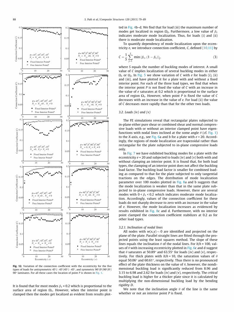
Fig. 12. Variation of the connection coefficient with the eccentricity for the fivetypes of loads for antisymmetric 45�/�45�/45�/�45�, and symmetric 90�/0�/90�/0�/90� laminates. For all these cases the location of point P is shown in Fig. 1.
88 S. Paik et al. / Composite Structures 120 (2015) 79–89
It is found that for most modes b1 = 0.2 which is proportional to thesurface area of region X1. However, when the interior point isclamped then the modes get localized as evident from results plot-
ted in Fig. 4b–d. We find that for load (iii) the maximum number ofmodes get localized in region X2. Furthermore, a low value of b1
indicates moderate mode localization. Thus, for loads (i) and (ii)there is moderate mode localization.
To quantify dependency of mode localization upon the eccen-tricity e, we introduce connection coefficient, C, defined [10,11] by
C ¼ 1S
XS
j¼1
min ðb1; ð1� b1ÞÞj; ð3Þ
where S equals the number of buckling modes of interest. A smallvalue of C implies localization of several buckling modes in eitherO1 or O2. In Fig. 5 we show variation of C with e for loads (i), (ii)and (iii), and have plotted it for a plate with and without a fixedinterior point. For each of the three load types, we find that whenthe interior point P is not fixed the value of C with an increase inthe value of e saturates at 0.2 which is proportional to the surfacearea of region X1. However, when point P is fixed the value of Cdecreases with an increase in the value of e. For load (ii) the valueof C decreases more rapidly than that for the other two loads.
3.2. Loads (iv) and (v)
The FE simulations reveal that rectangular plates subjected toin-plane either pure shear or combined shear and normal compres-sive loads with or without an interior clamped point have eigen-functions with nodal lines inclined at the some angle h (cf. Fig. 1)to the X-axis, e.g., see Fig. 6a and b for a plate with e = 20. Accord-ingly, the regions of mode localization are trapezoidal rather thanrectangular for the plate subjected to in-plane compressive loadsonly.
In Fig. 7 we have exhibited buckling modes for a plate with theeccentricity e = 20 and subjected to loads (iv) and (v) both with andwithout clamping an interior point. It is found that, for both loadtypes, the clamping of an interior point does not affect the bucklingload factor. The buckling load factor is smaller for combined load-ing as compared to that for the plate subjected to only tangentialtractions on the edges. The distribution of mode localizationparameter over 100 modes plotted in Fig. 8a and b suggests thatthe mode localization is weaker than that in the same plate sub-jected to in-plane compressive loads. However, there are severalmodes with 0 < b1 < 0.2 which indicates moderate mode localiza-tion. Accordingly, values of the connection coefficient for theseloads do not sharply decrease to zero with an increase in the valueof e. However, the mode localization increases as evidenced byresults exhibited in Fig. 8c and d. Furthermore, with no interiorpoint clamped the connection coefficient stabilizes at 0.2 as forother load types.
3.2.1. Inclination of nodal linesAll nodes with w(x,y) � 0 are identified and projected on the
plane of the plate. Parallel straight lines are fitted through the pro-jected points using the least squares method. The slope of theselines equals the inclination h of the nodal lines. For b/h = 100, val-ues of h with increasing eccentricity plotted in Fig. 6c and d suggestthat h saturates at 50.89� and 63.55� for loads (iv) and (v), respec-tively. For thick plates with b/h = 10, the saturation values of hequal 50.06� and 60.61�, respectively. Thus there is no pronouncedeffect of the plate thickness on the value of h, however, the nondi-mensional buckling load is significantly reduced from 8.96 and3.15 to 6.98 and 2.62 for loads (iv) and (v), respectively. The criticalbuckling load is higher for a thicker plate since it is calculated bymultiplying the non-dimensional buckling load by the bendingrigidity D.
We note that the inclination angle h of the line is the samewhether or not an interior point P is fixed.

S. Paik et al. / Composite Structures 120 (2015) 79–89 89
4. Buckling mode localization in orthotropic laminae andlaminates
We first investigate mode localization in 0�, 90� and 45� lami-nae and then in laminates composed of these laminae of uniformthickness, b/h = 50, and with material parameters having the fol-lowing values: E1/E2 = 25, G12/E2 = 0.5, G23/E2 = 0.2, and m12 = 0.25.The buckling of laminates is analyzed using an equivalent singlelayer theory.
In Fig. 9 we show the distribution of parameter b1 over first 100out-of-plane bending modes for the 0�, 45� and 90� laminae underall five types of loads with a fixed interior point. For each one of thefive load types, compared to the 45� and the 90� laminae, the 0�lamina has most modes centered at b1 = 0.2 indicating very littlemode localization. For the 90� lamina mode localization for loadcase (ii) is very strong since nearly 40% of the modes are localizedin the region X2. In Fig. 10 the degree of mode localization is plot-ted against the plate eccentricity for the 0�, 45� and 90� laminae. Asbefore for the 0� lamina, the degree of mode localization does notincrease with an increase in the plate eccentricity. The degree ofmode localization for the 45� and the 90� lamina is found toincrease significantly with the increase in the plate eccentricityfor load types (v) and (ii), respectively. In general, for the 45� andthe 90� laminae the degree of mode localization increases withan increase in the eccentricity.
The variation in the degree of mode localization with the plateeccentricity in two-layered anti-symmetric cross-ply (0�/90�) andangle-ply (45�/�45�) laminates, and in three-layered symmetriccross-ply 0�/90�/0� and 90�/0�/90� laminates for all five load casesis shown in Fig. 11. These results evince that for cross-ply lami-nates, symmetric or anti-symmetric either there is no appreciablemode localization with increasing aspect ratio or there is no cleartrend. For the 45�/�45� laminates subjected to the loads (i), (ii)and (iii) the degree of mode localization is found to increase withan increase in the aspect ratio of laminates. However, the 4-layerangle-ply and the 5-layer cross-ply laminates show only a moder-ate degree of mode localization as shown in Fig. 12. These resultsare consistent with those found for the localization of modes offree vibrations in laminates [11] in the sense that localization ofmodes of vibration in laminates depends upon the localization ofmodes in individual lamina.
5. Conclusions
By using the Mindlin plate theory and the finite elementmethod with 8-node quadrilateral uniform elements, we have ana-lyzed buckling of clamped–clamped rectangular isotropic plates,orthotropic laminae, and orthotropic laminates with and withoutfixing points on the transverse normal passing through an interiorpoint for five different in-plane loading conditions. It is found thatfixing an interior point divides the plate into two independentregions such that in one of these regions plate’s deformations are
negligible. For in-plane compressive normal loads on the edges,the two regions are rectangular. However, for in-plane shear orin-plane shear with in-plane normal compressive loads, the tworegions are trapezoidal. The inclination of the line passing throughthe fixed interior point that divides the plate into two regionsdepends upon the ratio of the plate thickness to the plate width,and the load type. It is found that the localization is pronouncedwhen plates are subjected to in-plane normal compressive loadsthan that when they are subjected to in-plane shear or in-planeshear and in-plane normal compressive loads. The degree of local-ization increases with an increase in the aspect ratio of a plate. It isenvisaged that fixing an interior point can be used to control buck-ling failure of plates/laminates.
Acknowledgement
SSG’s work was supported by the Office of Naval Research Glo-bal Grant No. N62909-14-1-V155 with Dr. Ramesh Kolar as theAssociate Director and RCB’s work was supported by the Office ofNaval Research Grant No. N00014-11-1-0594 with Dr. Y.D.S. Rajap-akse as the Program Manager.
References
[1] Hodges CH. Confinement of vibration by structural irregularity. J Sound Vib1982;82(3):411–24.
[2] Pierre C, Dowell EH. Localization of vibrations by structural irregularity. JSound Vib 1987;114(3):549–64.
[3] Pierre C, Plaut RH. Curve veering and mode localization in a buckling problem.J Appl Math Phys 1989;40:758–61.
[4] Nayfeh AH, Hawwa MA. Use of mode localization in passive control ofstructural buckling. AIAA J 1994;32(10):2131–3.
[5] Li YW, Elishakoff I, Starnes Jr JH. Buckling mode localization in multi-spanperiodic structure with a disorder in a single span. Chaos Solitons Fractals1995;5(6):955–69.
[6] Elishakoff I, Li YW, Starnes Jr JH. Buckling mode localization in elastic platesdue to misplacement in stiffener location. Chaos Solitons Fractals1995;5(8):1517–31.
[7] Xie W-C, Ibrahim A. Buckling mode localization in rib-stiffened plates withmisplaced stiffeners – a finite strip approach. Chaos Solitons Fractals2000;11(10):1543–58.
[8] Xie W-C. Buckling mode localization in nonhomogeneous beams on elasticfoundations. Chaos Solitons Fractals 1997;8(3):411–31.
[9] Brasil RM, Hawwa MA. The localization of buckling modes in nearly periodictrusses. Comput Struct 1995;56(6):927–32.
[10] Filoche M, Mayboroda S. Strong localization induced by clamped point in thinplate vibration. Phys Rev Lett 2009;103:254301.
[11] Sharma D, Gupta SS, Batra RC. Mode localization in composite laminates.Compos Struct 2012;94:2620–31.
[12] Verma D, Gupta SS, Batra RC. Vibration mode localization in single- and multi-layered graphene nanoribbons. Comp Mater Sci 2014;95:41–52.
[13] User’s manual 2005, MATLAB. The Math Works Inc., MA, USA.[14] Timoshenko [14]S, Gere M. Theory of elastic stability. McGraw Hill
International Book Company; 1985.[15] Shufrin I, Eisenberger M. Shear buckling of thin plates with constant in-plane
stresses. Int J Struct Stab Dyn 2007;7(2):179–92.[16] Shufrin I, Rabinovitch O, Eisenberger M. Buckling of symmetrically laminated
rectangular plates with general boundary conditions – A semi analyticalapproach. Compos Struct 2008;82(4):521–31.